Preprint
Article

Analysis of Steering Performance for All-Terrain Wheel-Track Composite Unmanned Vehicle in Complex Environment

Altmetrics

Downloads

115

Views

34

Comments

0

This version is not peer-reviewed

Submitted:

29 August 2023

Posted:

30 August 2023

You are already at the latest version

Alerts
Abstract
In order to solve the problems of complicated steering control of unmanned vehicles in the field and difficult steering on complex roads, we designed a wheel-track composite vehicle equipped with a novel power differential steering mechanism with dual driving, which drove the steering of the vehicle through the differential rotation of the rear two wheels. The unmanned vehicle was simple to control, small in size, and able to work under the conditions of complex roads, such as hills, mountains, and muddy land. Firstly, a steering mechanism with both differential speed and force was designed to prevent the vehicle from skidding into muddy land and stopping motionless. Secondly, the kinematics model and dynamics model of the two drive shafts and the two output shafts (wheel shafts) were established. Thirdly, according to the relationship between the rotational speed of the two output shafts and the steering radius of the vehicle, the kinematic model of the rotational speed of the two input shafts and the steering radius of the wheel-track composite vehicle was obtained. Finally, according to the test data, the mathematical model of rotational speeds of the two input shafts and the actual steering radius of the vehicle was obtained by neural network fitting, and the maximum relative error between the model results and the actual steering radius value was 3.53%. The combination of power differential steering mechanism and wheel-track composite unmanned vehicle increased the adhesion with the ground and could better adapt to the complex road environment. In conclusion, the unmanned vehicle had the advantages of continuous radius steering, deceleration and torsion increase, differential lock, etc. It was suitable for all-terrain military and civilian vehicles and various special equipment mobile platforms of the walking device, and the research results could provide theoretical references for the steering control and structural optimization of the wheel-track composite vehicle under the environment of complex road surface.
Keywords: 
Subject: Engineering  -   Automotive Engineering

1. Introduction

In China, hilly and mountainous areas account for about 70% of the country's land area, with large slopes and complex environments, making it impossible for many large-scale equipment to work. Small and flexible operational vehicles have broad application prospects in complex and harsh environments such as agriculture, security surveys and reconnaissance [1]. The small unmanned vehicles with ease in operational control could be used for precision agriculture maneuvers like crop scouting, inter- and intra-row mechanical weeding, as well as precise spraying and fertilizing applications [2]. In recent years, researchers had identified small unmanned vehicles as the key to a "paradigm change" in agricultural machinery systems, which could not only reduce long-term environmental impacts and energy consumption, but also provide greater machine autonomy and precision.[3] Currently, most of the small unmanned vehicles used the independent drive steering mode in the steering process. Khot et al. [3] designed a four-wheel-steered (4WS), four-wheel-driven (4WD) small agricultural robotic vehicle (AgRV) in Agricultural Robotics Laboratory at the Iowa State University. The steering performance of the vehicle for better maneuverability was studied using coordinated, crab and conventional steering systems. Bawden et al. [4] designed a lightweight, modular robotic vehicle for the sustainable intensification of agriculture. The robot had been designed with a user-centered approach which focuses the outcomes of the project on the needs of the key project stakeholders. Youn et al. [5] presented an active steering control system (ASCS) for an independent wheel drive electric vehicle (EV). The ASCS would manoeuvre the independently actuated (IA) all-wheel drive (AWD) EV via coordinating the angular velocities of the four wheels plus active front steering (AFS). Khan et al. [6] investigated a robust differential steering control system (DSCS) for an independent four-wheel drive electric vehicle (EV). The DSCS would maneuver the independently actuated (IA) four-wheel drive EV without the help of any conventional steering mechanism (CSM) via the input torque of the four wheels. Nie et al. [1] designed a new bow-waisted mobile chassis, the steering mechanism of which consists of a steering motor, a worm gear reducer, and a steering shaft, etc. The steering motor is used as the power source to control the steering angle of the chassis by controlling the angle that the steering motor turns over. Although the use of independent drive steering mode could realize a variety of steering modes, steering flexibility, but the structure was more decentralized, large space occupation and more complex control system.
In tracked vehicle steering research, the steering performance as an important symbol of tracked vehicle maneuverability had attracted a wide range of scholars. Jing et al. [7] investigated the power flow characteristics of the tracks on both sides of a tracked vehicle steering under different steering radii and the working principle of hydraulic stepless differential steering mechanism. Cao et al [8]. performed kinematic and dynamical modeling of a hydromechanical dual power flow differential steering mechanism in a tracked vehicle and performed steering motion performance analysis. Gao et al. [9] studied the unmanned agricultural power chassis steering device, proposing the use of motor to compensate for power differential steering, and adjusting the motor speed to meet the various steering needs of tracked vehicles. Shi et al. [10] established the mechanical model of the differential steering mechanism of the track vehicle in the process of steering and driving, and derived the theoretical model of the two motor shafts (input) rotational speed and the two axle shafts (output) rotational speed of the two differential steering mechanisms, which provides the theoretical basis for the structural design and parameter selection and control of the differential steering mechanism. Differential steering mechanism could provide flexible steering for tracked vehicles. Therefore, this paper applied the differential steering mechanism in wheeled vehicles to wheel-track composite vehicles and improved the differential steering mechanism so that it could perform both differential speed and force. The combination of the power differential steering mechanism and the wheel-track composite vehicle made it more suitable for working in complex environments in the field. Differential drive through the rear wheels made the wheel-track composite unmanned vehicle simple to control and flexible to steer. However, the current research on the steering performance of wheel-track composite vehicles did not consider the specific steering mechanism [11,12]. Therefore, it was more relevant to study the steering performance of wheel-track composite vehicles by considering the driving steering performance of the steering mechanism than the traditional method.
Currently, clutch steering mechanism, mechanical dual power flow steering mechanism, hydraulically driven steering mechanism and hydraulically and mechanically driven combined steering mechanism are generally used for steering in vehicles. The traditional clutch steering mechanism not only generates a lot of frictional heat when steering, but also has difficult to control the steering trajectory and low working efficiency [8]. The purely mechanical dual power flow steering mechanism, where the steering radius is graded, cannot exclude the partial engagement of the friction assembly for slip-grinding steering and the series of problems caused by slip-grinding. The advantages of the pure hydraulic drive steering mechanism and the hydraulic-mechanical combined drive steering mechanism are the ability to achieve stepless variable speed and flexible configuration on the chassis, but its disadvantages are complex structure, high cost and low efficiency [13,14]. Combining the advantages and disadvantages of the above steering mechanism, a new type of differential steering mechanism with twin driving capable of continuous steering radius was designed in this paper. The steering mechanism was a new type of differential steering mechanism with composite fixed gear system and planetary gear system transmission, with two planetary rows can make the vehicle both differential speed and differential force in the process of driving, to overcome the problem of one side of the driving wheel into the mud puddle skidding to make the vehicle stop. The overall structure of the steering mechanism is simple and centralized, with high transmission efficiency, which can achieve high-speed steering, high stability and straight-line driving. It could not only use a variety of drive forms (including motor and engine drive), and was suitable for all-terrain military and civilian wheeled, tracked or wheel-tracked composite vehicles and a variety of special equipment mobile platform walking device. In this paper, the steering motion control of wheel-track composite vehicles was investigated by taking the electric motor drive as an example and combining the characteristics of differential steering mechanism with dual driving.

2. Design of differential steering mechanism with dual driving

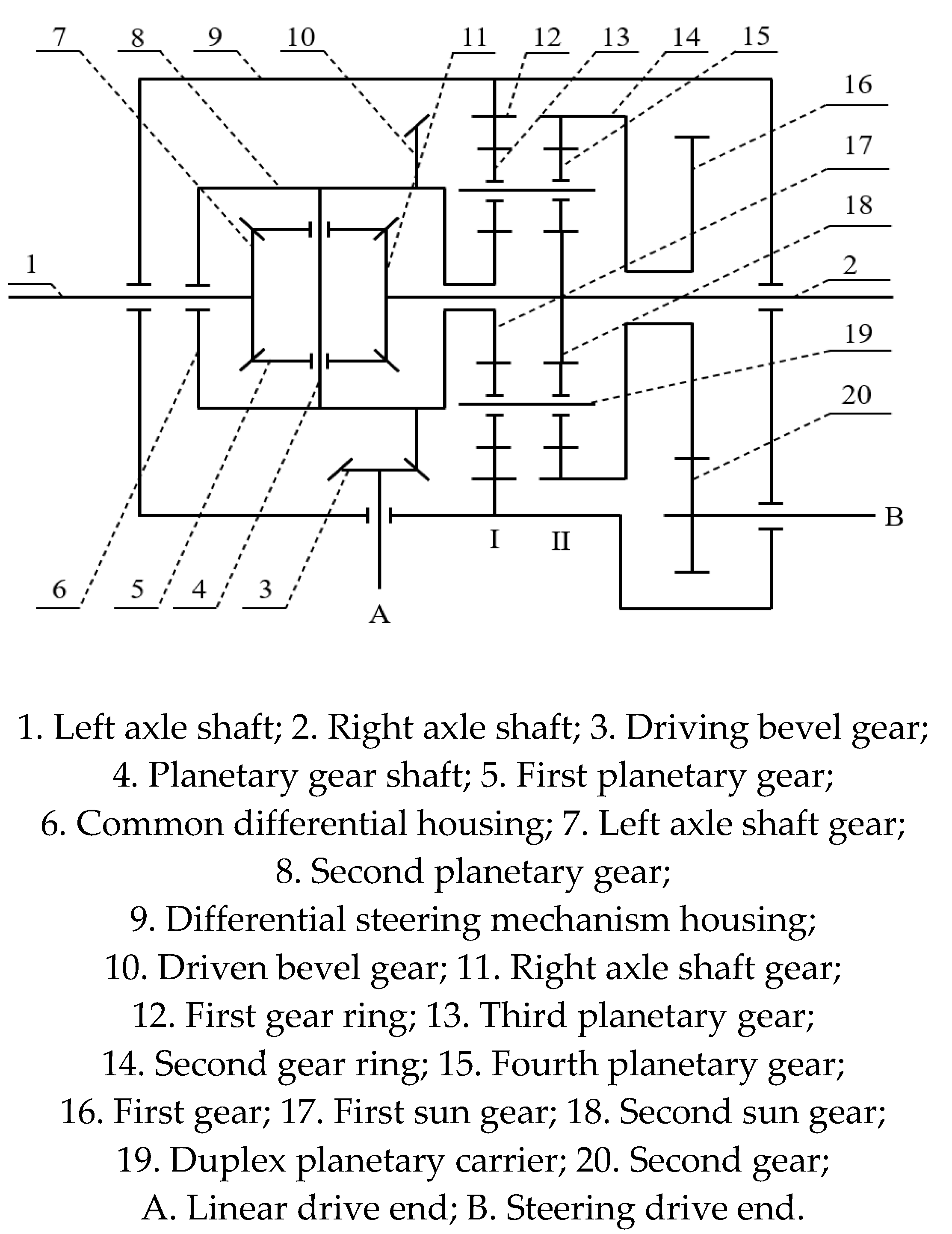
Figure 1 showed the designed differential steering mechanism with dual driving, which consisted of common differential, planetary row I, planetary row II, planetary carrier, differential steering mechanism housing, and left and right axle shafts. The engagement relationship between them was that the connection structure of common differential housing and the first sun gear engaged with the planetary gear of planetary row I, and the second sun gear connected with the right axle shaft engaged with the planetary gear of planetary row II. The internal meshing gear of the planetary row I was fixedly connected to the differential steering mechanism housing. The planetary row I and the planetary row II shared the same planetary carrier. The internal meshing gear of planetary row II was fixedly connected with the first gear.
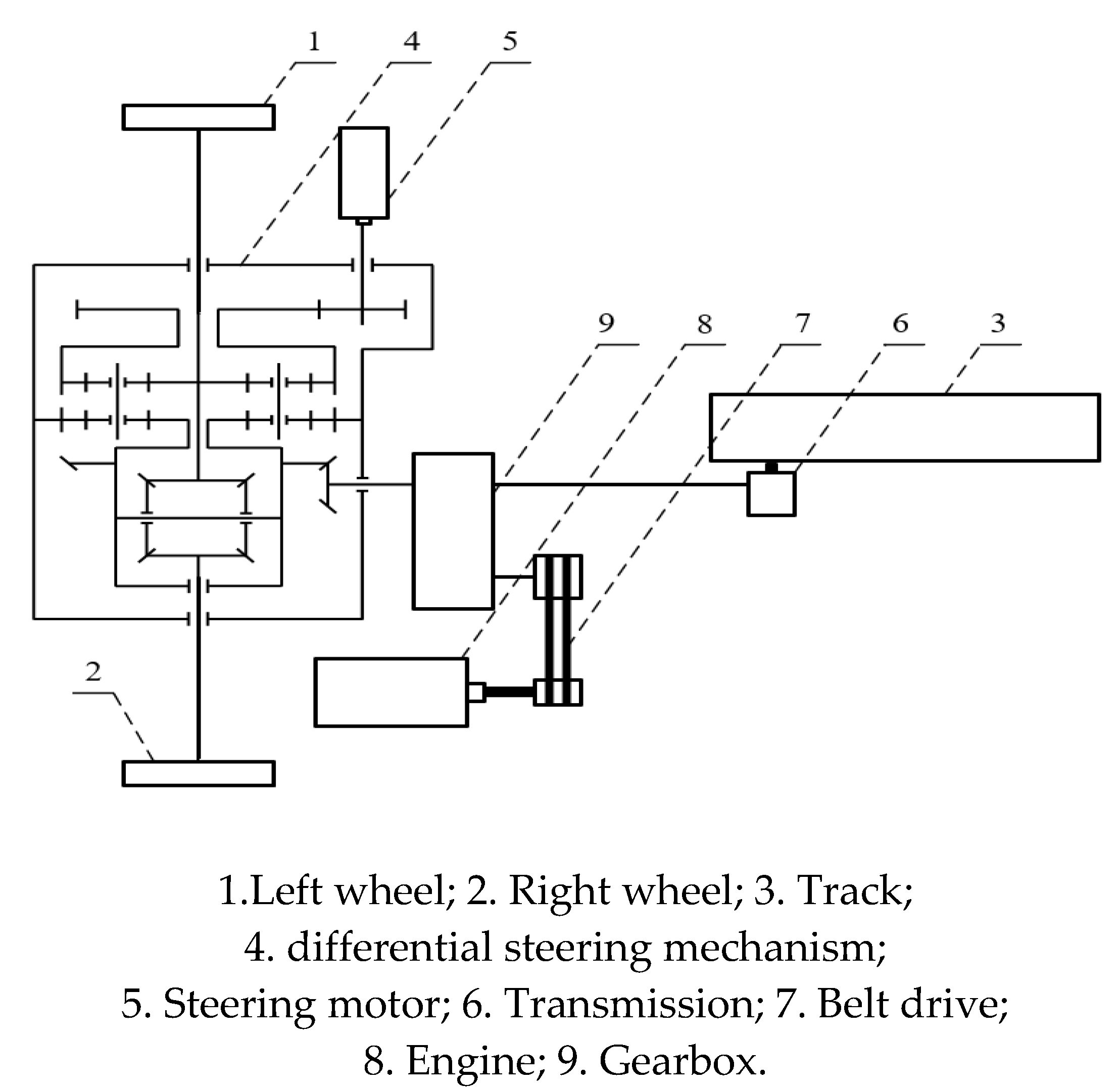
The principle of the wheel-track unmanned composite vehicle transmission system was shown in Figure 2. The engine supplied power to the linear drive end through the belt and gearbox, and the steering motor supplies power directly to the steering drive end. The power input from the linear drive end and the steering drive end were converged in the differential steering mechanism and then output to the left and right axle shafts by the differential steering mechanism with dual driving. The power input from the engine made both axle shafts to rotate at the same speed, thus moving the vehicle forward or backward. The power input from the steering drive could increase the speed of the axle shaft on one side and decrease the speed of the axle shaft on the other side. The speed of two axle shafts increased or decreased by the same amount. The two axle shafts produced the effect of differential speed steering, thus enabling the wheel-track composite vehicle to steer.
By adjusting the size and direction of the rotational speeds of the two input shafts, it was possible to control the wheel-track composite vehicle to turn to the left and to the right with different radii. Usually there were three different operating conditions of differential steering mechanism.
(1) The linear drive end worked and the steering drive end did not;
(2) The steering drive end worked and the linear drive end did not;
(3) The linear drive end and the steering drive end worked at the same time.
The prototype of the power differential steering mechanism was shown in Figure 3.
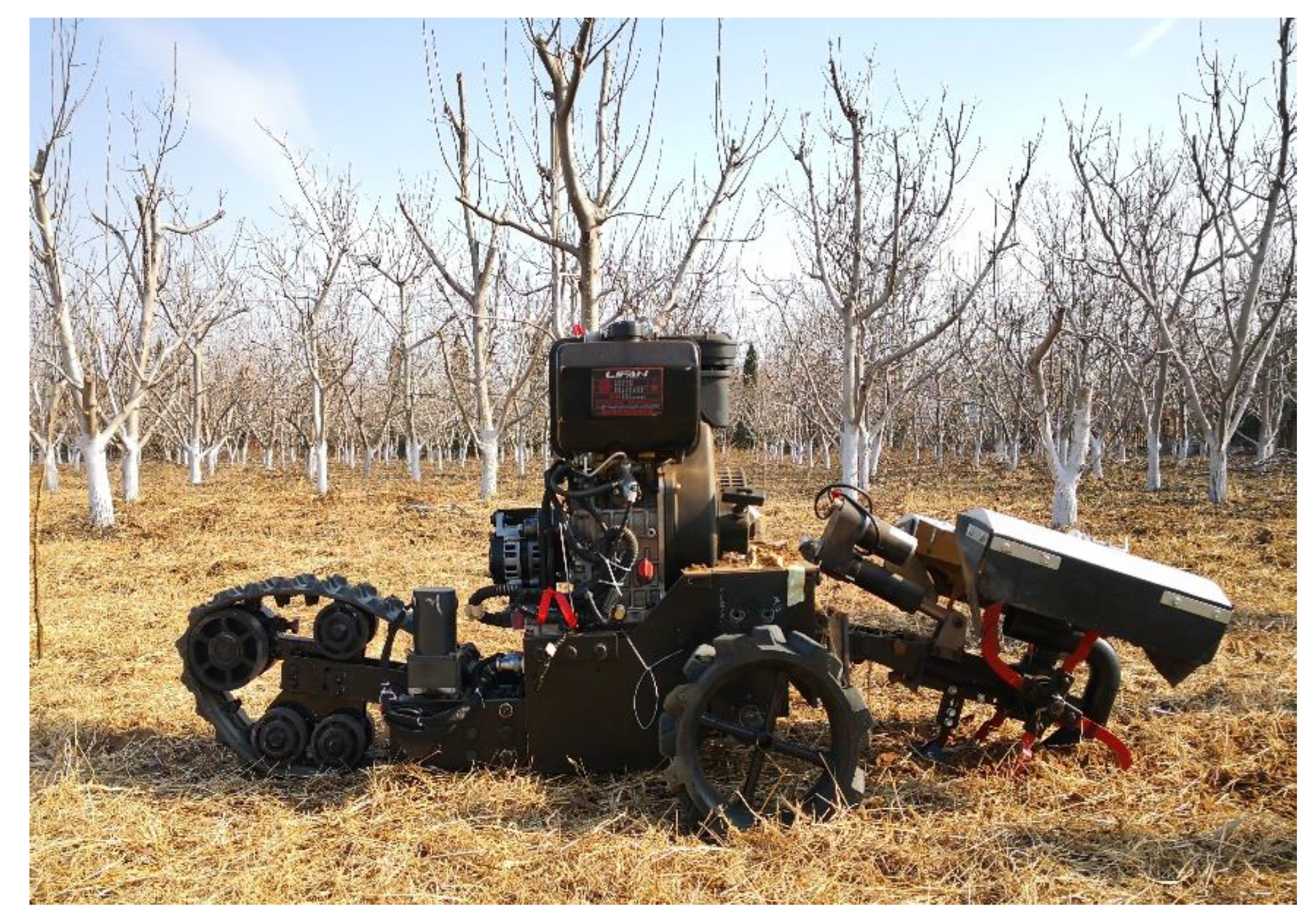
The prototype of the wheel-track composite unmanned vehicle was shown in Figure 4.

3. Kinematic and dynamic analysis of the differential steering mechanism

3.1. Kinematic analysis of the differential steering mechanism

Combining the planetary gear characteristics and Figure 1, the speed relationship of each component of the differential steering mechanism could be obtained.
n 1 + n 2 = 2 n 10
n 17 + α n 12 1 + α 1 n 19 = 0
n 18 + α n 14 1 + α 2 n 19 = 0
In formulas,
n 1 - rotational speed of left axle shaft(rad/s);
n 2 - rotational speed of right axle shaft(rad/s);
n 10 - rotational speed of the driven gear of the master reducer(rad/s);
n 12 - rotational speed of the first ring gear(rad/s);
n 14 - rotational speed of the second ring gear(rad/s);
n 17 - rotational speed of the first sun gear(rad/s);
n 18 - rotational speed of the second sun gear(rad/s);
n 19 - rotational speed of the planetary carrier (rad/s);
α 1 - characteristics parameter of the planetary row of I;
α 2 - characteristics parameter of the planetary row of II.
According to formulas (1) to (3), the rotational speeds of the two axle shafts of the wheel-track composite vehicle were as follows.
n 1 = i 1 n 3 α i 2 n 20
n 2 = i 1 n 3 + α i 2 n 20
In formulas,
i 1 - transmission ratio between the driving bevel gear and the driven bevel gear;
i 2 - transmission ratio between the second gear and the first gear;
α - characteristics parameter of the planetary row, and α = α 1 = α 2 ;
n 3 - input rotational speed of the linear drive end(rad/s);
n 20 - input rotational speed of the steering drive end(rad/s).
According to formulas (4) and (5), when the linear drive end and the steering drive end worked at the same time, i.e., n 3 0 and n 20 0 . The clockwise direction was set as the positive direction. As shown in Figure 5, when the steering drive end rotated clockwise, and if the linear drive end also rotated clockwise (i.e., when n 3 > 0 and n 20 > 0 ), then n 2 > n 1 . In this case, the wheel-track composite vehicle would turn left. If the linear drive end rotated counterclockwise (i.e., when n 3 < 0 and n 20 > 0 ), then n 2 < n 1 . The wheel-track composite vehicle would turn right. When the steering drive end worked counterclockwise, and if the linear drive end turned clockwise (i.e., when n 3 > 0 and n 20 < 0 ), then n 2 < n 1 . In this case, the wheel-track composite vehicle would turn right. If the linear drive end turned counterclockwise (i.e., when n 3 < 0 and n 20 < 0 ), then n 2 > n 1 . The wheel-track composite vehicle would turn left.
Specially, when i 1 n 3 = α i 2 n 20 , then n 1 = 0 , and the wheel-track composite vehicle would steer around the left driving wheel center. When i 1 n 3 = α i 2 n 20 , then n 2 = 0 , and the wheel-track vehicle would turn around the center of the right driving wheel.
The direction of the left and right wheels speed under various operating conditions of the steering mechanism were shown in Table 1, where "+" indicated clockwise low-speed rotation, "-" indicated counterclockwise low-speed rotation, "0" indicated zero speed, and "++" indicated clockwise high-speed rotation.
The speed of the left and right sides drive wheels could be controlled by controlling the size and direction of the input speed of the two drive ends from Table 1. The three driving states of the wheel-track composite vehicle were realized.

3.2. Kinetic analysis of the differential steering mechanism

The theoretical torque relationship obtained from the two planetary stages was shown without considering the transmission efficiency.
M 17 = M 12 α = M 13 ( 1 + α )
M 18 = M 14 α = M 15 ( 1 + α )
In formulas, M 17 , M 12 and M 13 respectively were the theoretical internal torque of the planetary wheel acting on the sun wheel, tooth ring and planetary carrier in the planetary row I. M 18 , M 14 and M 15 respectively were the theoretical internal torque of the planetary wheel acting on the sun wheel, tooth ring and planetary carrier in the planetary row II.
The output torque of the two axle shafts could be obtained as follows from the static equilibrium equations of the rotating members in the mechanism as well as formulas (6) and (7).
M 1 = α 1 + α i 1 M A + 1 + α α i 2 M B
M 2 = α 1 + α i 1 M A 1 + α α i 2 M B
In formulas,
M 1 - output torque of the left axle shaft;
M 2 - output torque of the right axle shaft;
M A - input torque of the linear drive end;
M B - input torque of steering drive end.
When the output torque of the left and right axle shafts was known, the input torque of the two drive shafts could be obtained by formulas (8) and (9).
M A = 1 + α 2 α i 1 ( M 1 + M 2 )
M B = α 2 ( 1 + α ) i 2 ( M 1 M 2 )

3.2.1. Separate operation for linear driving end

When torque M A was input to the linear drive and torque was not input to the steering drive ( M B =0), the vehicle was driven in a straight line.
When the left and right sides of the road conditions were the same, i.e., M 1 = M 2 . At this time, the output torque of the left and right ends of the mechanism were equal in value and had the same direction. The mechanism distributed the torque provided by the output shaft of the gearbox to the left and right output shafts equally, so the differential steering mechanism was characterized by equal distribution of torque.
When the road conditions on the left and right sides were significantly different, the load on the two driving wheels would be unequal because of the limitation of the driving wheels by the adhesion conditions. It affected the change of the output torque of the differential steering mechanism, resulting in M 1 M 2 . The input torque of the steering drive end was proportional to the difference in the adhesion force on the two sides from the formula (9). When traveling in a straight line, the rotational speed of the steering drive source was 0. If the attachment torques on both sides were not equal, the steering drive end would still be subjected to torque. At this time, the planetary row II was engaged in the power transmission. The torque was transferred to the second gear ring 14 through the first gear 16. Subsequently, the planetary row II converted the torque from one end to the other end. The amount of decrease at one end corresponded to an equal increase at the other end. From equations (8) and (9), ( 1 + α / α ) i 2 M B 0 . If ( 1 + α / α ) i 2 M B > 0 , then M 1 > M 2 . If ( 1 + α / α ) i 2 M B < 0 , then M 1 < M 2 . When the road attachment condition was poor on one side, a larger torque could be obtained for the side with the good road condition. Thus, the passing performance of the vehicle was improved. It made the mechanism have differential performance and play the effect of differential lock at the same time. Due to ( 1 + α / α ) i 2 M B 0 , then M B 0 . Therefore, the steering drive end was converted from a power source to a load.
The steering drive end would generate an output rotational speed during steering from formulas (8) and (9). But if the adhesion forces on both sides were equal, the motor did not produce any torque output.

3.2.2. Separate operation of the steering drive end

In this state, the gearbox was positioned in neutral. The gear shafts of the gearbox remained free and unable to transmit torque, i.e., M A = 0 . When the input torque at the steering drive end was M B , the vehicle steered in place.
When the left and right sides of the road conditions were the same, i.e., M 1 = M 2 . The output torque on both sides was equal in size and opposite in direction, and the vehicle steered in place around its own center. The planetary row I was not engaged in the transmission, the planetary row II of the ring connection of the torque was equal to all by the steering drive end of the torque provided to the steering mechanism input.
When the road conditions on the left and right sides were significantly different, i.e., M 1 M 2 , and planetary row I was engaged in the transmission. The power was transmitted from one end to the other end which needed more power via planetary row I, and the amount of decrease at one end was equal to the amount of increase at the other end. From formulas (8) and (9), [ α / ( 1 + α ) ] i 1 M A 0 . If [ α / ( 1 + α ) ] i 1 M A > 0 , then M 1 > M 2 . If [ α / ( 1 + α ) ] i 1 M A < 0 , then M 1 < M 2 .
Due to the difference in input torque between the left and right sides, the vehicle would not steer strictly around its own center. At the same time, as the planetary row I was engaged in the transmission, the planetary carrier of planetary row I outputted torque, which was then transmitted to the output shaft of the linear drive end through the driven bevel gear. The linear drive end was converted from a power source to a load.

3.2.3. Simultaneous operation of both sides of the drive end

When the linear drive end and the steering drive end worked at the same time, the vehicle steered. From equations (8) and (9), M 1 + M 2 = 2 α i 1 M A / ( 1 + α ) . Due to α > 1 , so M 1 + M 2 > i 1 M A . It could be seen that the total output torque was greater than the input torque, so the steering mechanism had a certain deceleration and torque increasing effect [16].

4. Kinematic and dynamic analysis of the differential steering mechanism

4.1. Analysis of steering kinematics model for the wheel-track composite vehicle

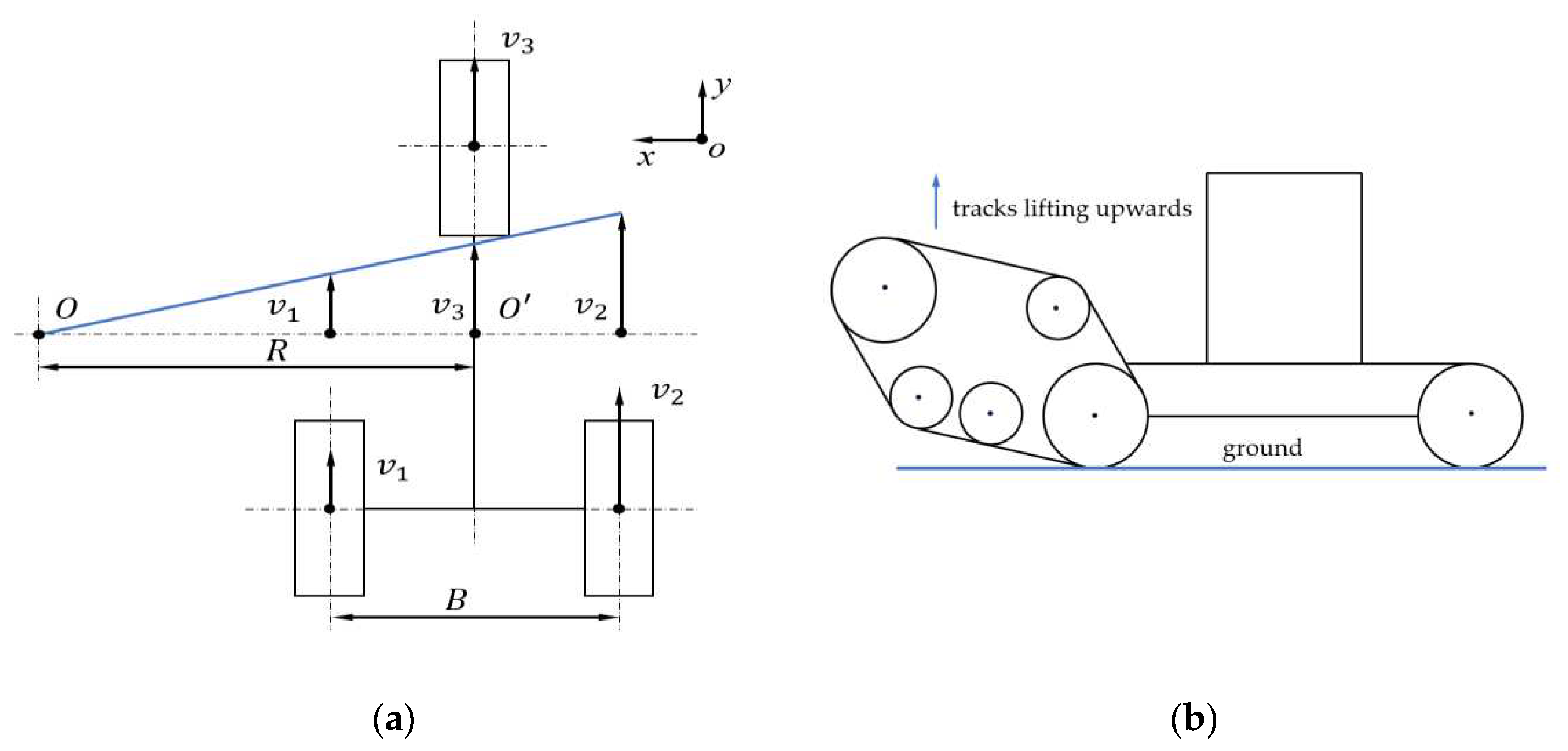
To analyze the steering characteristics of the wheel-track composite vehicle on the horizontal ground, the steering motion model was established as shown in Figure 6(a). And the following assumptions would be made about the steering motion of the vehicle in the traveling state.
(1) The slow steering speed of the tracked vehicle allowed the effect of centrifugal force during steering to be ignored.
(2) Grounding pressure was evenly distributed.
(3) The tracked vehicle made a steady state uniform steering motion on a horizontal should ground.
(4) The center of gravity of the vehicle was located at the intersection of the axes of symmetry.
Since the track of the wheel-track composite vehicle was lifted upward during turning, it was equivalent to grounding the wheel, as shown in Figure 6(b). In order to better explain the differential steering principle of the wheel-track composite vehicle in the presence of the differential steering mechanism with dual driving, the front track was simplified to a wheel. The wheel-track composite vehicle differential steering model was transformed into a three-wheeled vehicle differential steering model to be studied. Assuming that the model was steered to the left, the relationship between the velocities of the wheels on both sides and the steering radius was obtained according to the geometric relationship.
The kinematic model of the whole vehicle was shown in Figure 6(a). The coordinate system of xoy was the body coordinate system, where x pointed to the forward direction of the wheel-track composite vehicle. O point was the vehicle turning center, O' point was the own rotation center of vehicle, B point was the distance between the left and right wheel center, R point was the turning radius of vehicle, and v1, v2, and v3 were the forward speeds of the left wheel, right wheel, and front wheel, respectively.
The relationship between the velocities of the wheels on both sides and the steering radius was obtained according to the geometric relationship as shown in formulas (12) to (13).
v 1 = ω ( R 0.5 B )
v 2 = ω ( R + 0.5 B )
v 3 = ( v 1 + v 2 ) / 2
In the above formulas, ω represented the vehicle steering angular velocity. If the angular velocities of the driving wheels on both sides were ω1 and ω2 respectively, and the rolling radius of the driving wheels was denoted as r, the traveling speeds of the wheels on both sides were v 1 = r ω 1 and v 2 = r ω 2 respectively. Thus, the steering angular velocity ω could be obtained as follows.
ω = r ω 2 R + 0.5 B = r ω 1 R 0.5 B = r ( ω 2 ω 1 ) R + 0.5 B
The larger the difference in steering angular velocities ( ω 2 ω 1 ) between the wheels on both sides of the wheel-track composite vehicle, the greater the steering angular velocity ω of the vehicle, resulting in a smaller steering radius R.
Based on the above speed relationship and the kinematic model, the steering radius could be derived from the speed of two wheels.
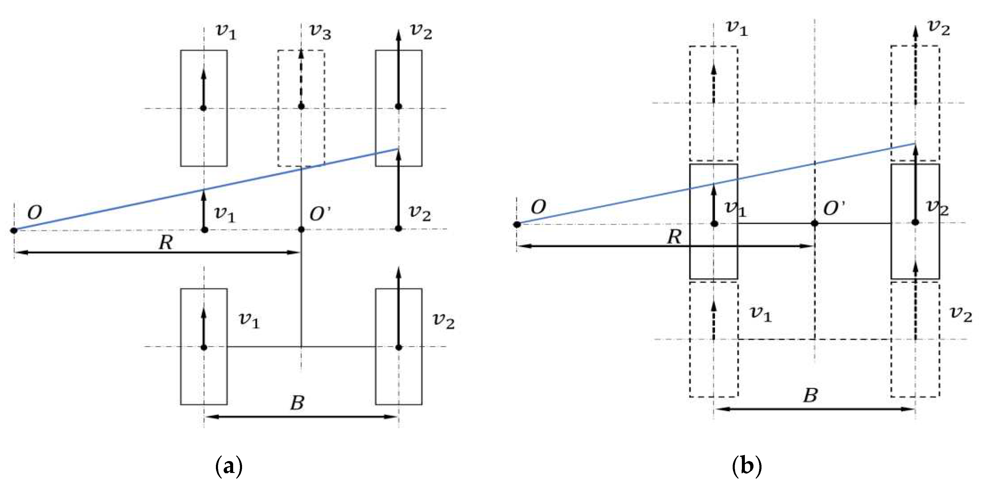
According to formulas (12) to (13) and Figure 7(a), the effect of converting the front wheels into two wheels on the differential steering of the vehicle was the same, and it would not change the steering radius of the vehicle. The vehicle needed to rely on the differential steering mechanism to achieve differential power distribution between the left and right axle shafts, and the four wheels did not swing during the steering process. In order to explore the impact of the differential steering mechanism on the rotational speeds of the driving wheels on both sides and analyze the relationship between input speed and steering radius, the four-wheel equivalent kinematic model was transformed into a two-wheel kinematic model [17,18]. Before and after the equivalence, the wheel rotational speeds and vehicle steering radius were not affected, and the simplified model of vehicle two-wheel steering was shown in Figure 7(b).
If the rotational speeds of the left and right output axle shafts were known, then
n 3 = 1 2 i 1 ( n 1 + n 2 )
n 20 = 1 2 α i 2 ( n 2 n 1 )
Therefore, the theoretical turning radius of the vehicle could be solved.
(1) As shown in Figure 8(a), if R > B 2 , according to v 1 v 2 = ( R B 2 ) / ( R + B 2 ) , v 1 = 2 π n 3 60 r and v 2 = r ( 2 π n 20 ) / 60 , then the radius of steering was expressed as follows.
R = n 2 + n 1 n 2 n 1 B 2 = n 3 i 20,1 n 20 i 3,1 B 2
(2) As shown in Figure 8(b), if 0 R B 2 , according to | v 1 | v 2 = ( B 2 R ) / ( R + B 2 ) , then the radius of steering was expressed as follows.
R = n 2 + n 1 n 2 n 1 B 2 = n 3 i 20,1 n 20 i 3,1 B 2
In formulas,
i 3,1 - transmission ratio from the linear drive end to the two axle shafts;
i 20,1 - transmission ratio from the steering drive end to the two axle shafts;
According to formulas (18) and (19), the size of the steering radius could be theoretically derived when the engine input speed and the steering drive motor input speed were known [5].
; (b) 0 R B 2 .
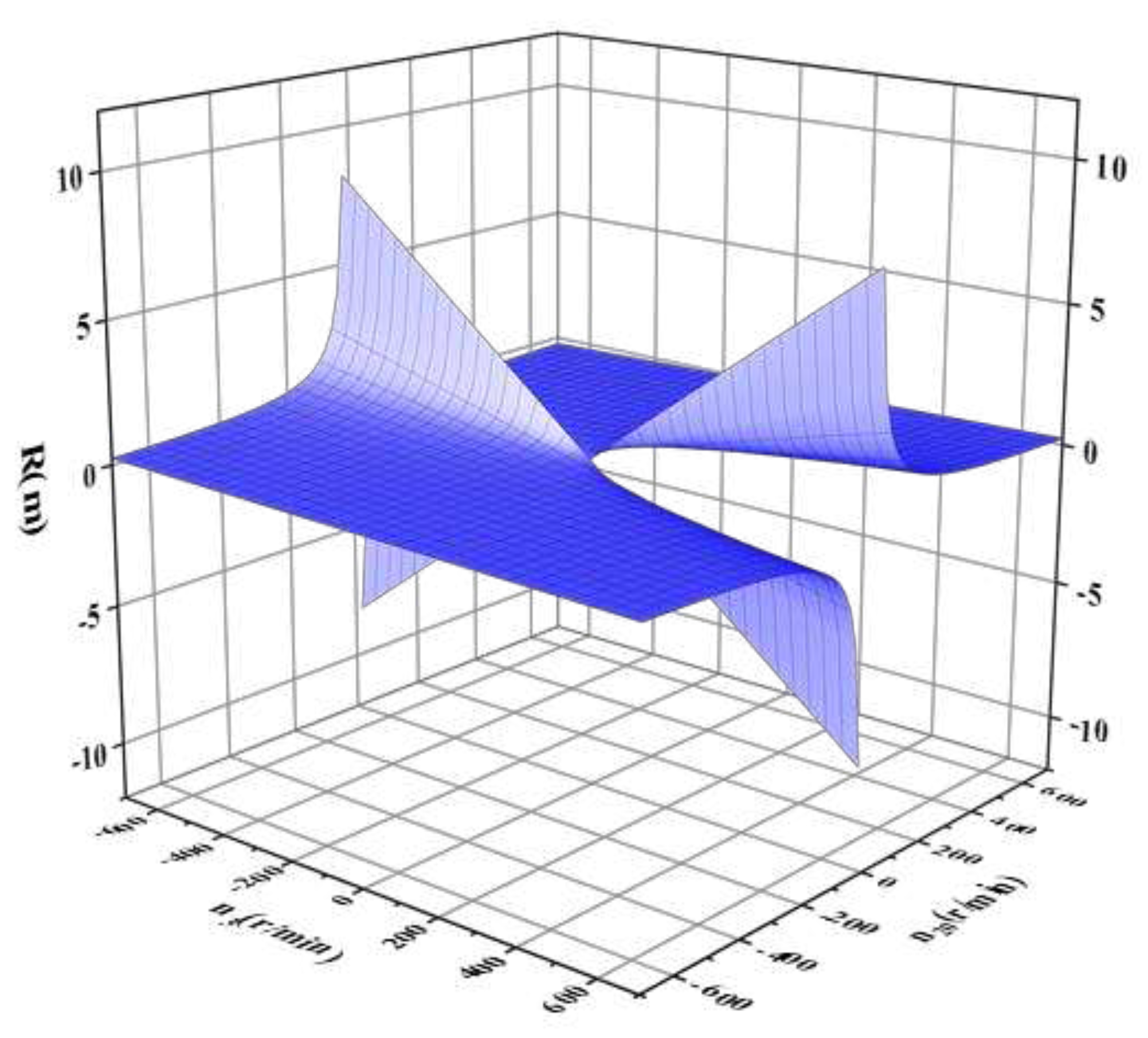
The relationship between the steering radius and the rotational speed of both driving ends was shown in Figure 9. It could be seen that the size of the steering radius increased with the increase of the input speed of the linear drive end and decreased with the increase of the input speed of the steering drive motor. The steering radius increased sharply when the input speed of the steering drive end tended to 0. The steering radius R was continuous in the interval (-10,10) m, indicating that the wheel-track composite vehicle equipped with the power differential steering mechanism could achieve an arbitrary continuous steering radius.
, the steering drive end speed of n 20 .
In order to verify the accurate steering capability of the differential steering mechanism for the wheel-track composite vehicle, the steering radius of the vehicle was investigated using the rotational speeds of the two drive ends of the differential steering mechanism as power inputs.
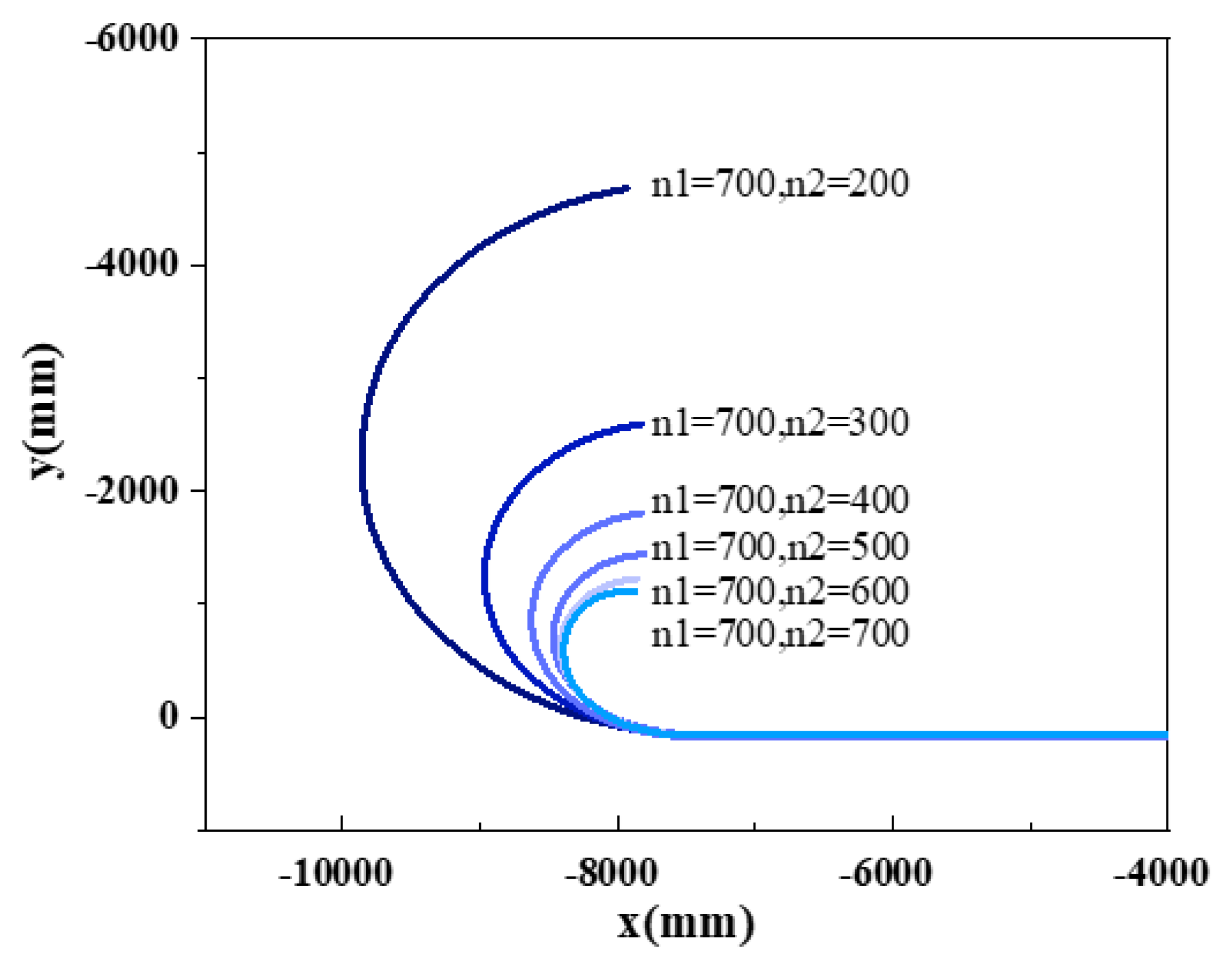
Under the land surface, setting the coefficient of static friction of the pavement to 0.8 and the coefficient of dynamic friction to 0.7. When the input speed of linear drive end was 700 rad/s, the input speed of steering drive end was respectively taken as 100, 200, 300, 400, 500, 600 and 700 rad/s, to observe the change of steering radius of the wheel-track composite vehicle under different working conditions, as shown in Figure 10.
From the Figure 10, the steering radius decreased with the increase of the speed of the steering drive end when the speed of the linear drive end was a constant value, and the wheel-track composite vehicle could achieve any continuous steering radius, which were consistent with the theoretical analysis and simulation results. Therefore, as long as the input speed of the two power sources were set reasonably, the vehicle could realize the steering of any continuous radius.

4.2. Fitting the steering radius of the wheel-track composite vehicle

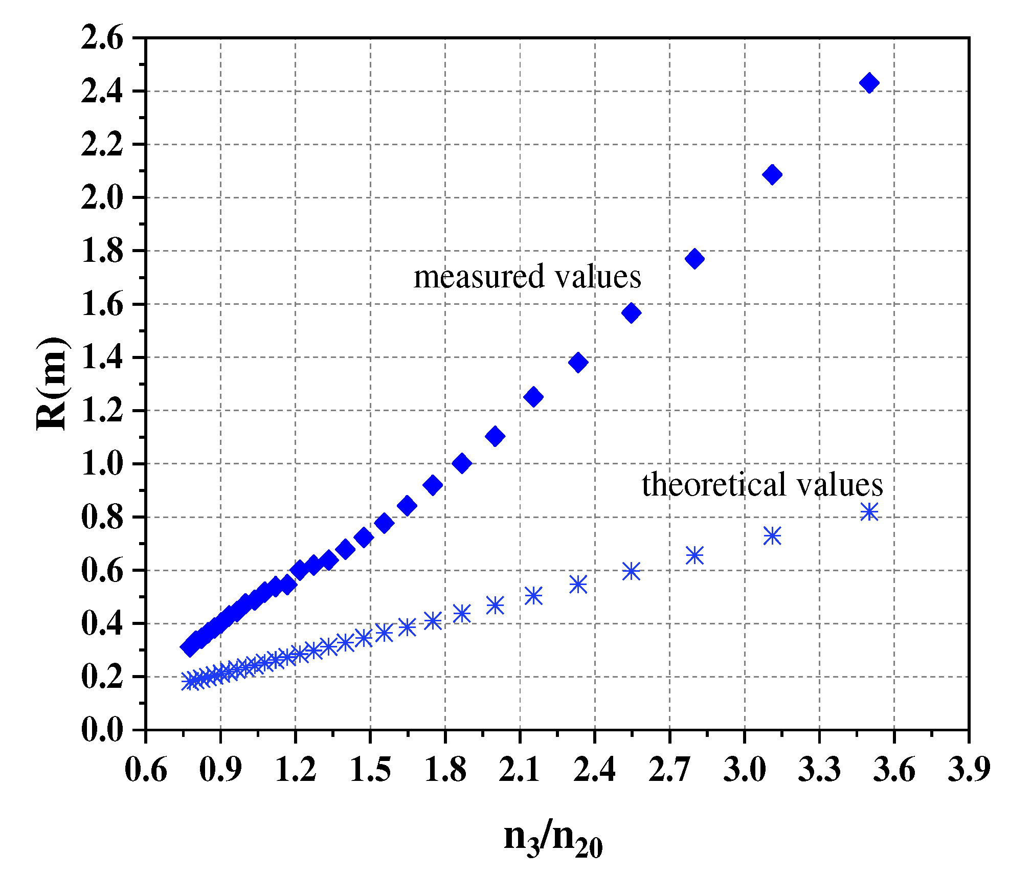
The speed of the two output shafts obtained from simulation were substituted into the formula of theoretical steering radius and the theoretical values were calculated. Comparing with the measured values of the same input speed ratio, it was found that the measured values were larger than the theoretical values, as shown in Figure 11. The measured values exceeded the theoretical values due to limitations in road adhesion during the steering of the wheel-track composite vehicle, resulting in the occurrence of slip and yaw phenomena on the vehicle's faster side.
Indeed, it was necessary to apply suitable driving or braking forces to the wheels during the steering of the wheel-track composite vehicle at varying speeds. The outer wheels consistently functioned as the driving force, resulting in a continuous sliding state. Conversely, the inner wheels could serve as either driving or braking forces, leading to potential slippage and sliding. Taking into consideration the occurrence of slip and slide, the actual steering radius was determined by the following equation [16].
R = B 2 ( 1 δ 2 ) n 2 + ( 1 δ 1 ) n 1 ( 1 δ 2 ) n 2 ( 1 δ 1 ) n 1
Wherein, δ 2 and δ 1 represented the outer and inner wheel slip rates, respectively.
As slip was present, the steering radius of the wheel-track composite vehicle was consistently greater than the steering radius in the absence of slip. It implied that slip contributed to an increase in the steering radius of the wheel-track combination vehicle.
Due to the practical challenges in measuring the slip rate, the aforementioned formula posed difficulties in accurately calculating the actual turning radius. This paper conducted experimental measurements of several actual steering radii, which were then compared and analyzed in relation to their theoretical counterparts. Based on the theoretical formula, a fitting process was performed to derive a formula for calculating the actual steering radius under identical ground conditions [16].
Formulas (18) and (19) could be expressed as the following function.
y = k x
In the function,
y - theoretical turning radius(m);
x - ratio of linear input speed to steering input speed of the power differential steering mechanism, that is, n 3 n 20 ;
k - constant coefficient, that is, k = i 20,1 i 3,1 B 2 = 0.2345 ;
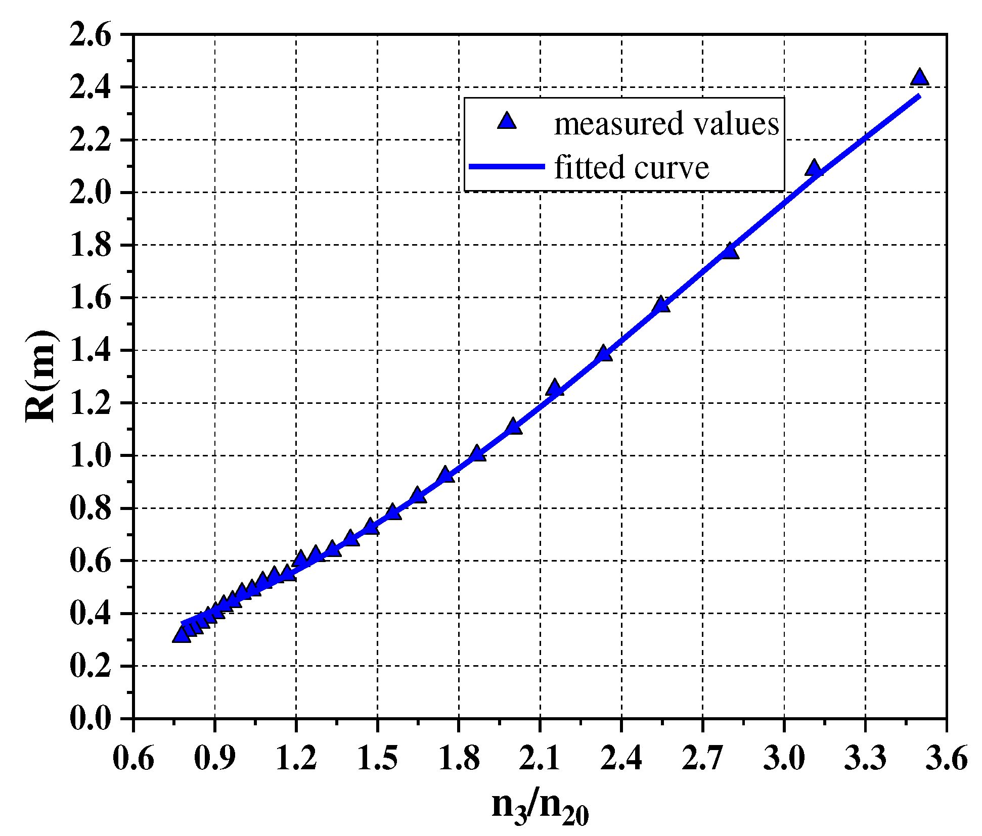
In this paper, a two-layer neural network consisting of one neuron in each layer was constructed. The function of the neuron in the first layer was a linear function, and the second layer was a sigmoid function, as shown in Figure 12. A more ideal prediction was obtained after several training sessions, and the curve fitting was shown in Figure 13. For the training of the first layer, the weight value was set as W 1 = 4.0867 , and the threshold was assigned as b 1 = 2.5790 . For the training of the second layer, the weight value was set as W 2 = 3.6735 , and the threshold was assigned as b 2 = 3.5269 .
The fitting function could be obtained as follows.
y = c 1 + e ( a k x + b ) + d
In the function,
a - weights of linear functions, and a = 4.0867 ;
b - thresholds of linear functions, and b = 2.5790 ;
c - weights of the sigmoid function, and c = 3.6735 ;
d - thresholds of the sigmoid function, and d = 3.5269 .
The actual steering radius fitting formula was as follows.
R = 3.6735 1 + e ( 4.0867 × 0.2345 n 3 n 20 + 2.5790 ) + 3.5269
In the formula,
R - actual turning radius(m);
n 3 n 20 - ratio of linear input speed to steering input speed.
The aforementioned formula represented the mathematical expression for the steering radius of the wheel-track combination vehicle equipped with the differential steering mechanism that was designed in this paper for the land surface. The actual steering radius was based on the speed ratio between the linear drive end and the input speed of the steering drive end of the power differential steering mechanism as the independent variable.
This formula showed that the steering radius decreases as the steering drive end increases for a constant value of the linear drive end. The larger the speed ratio between the linear drive end and the steering drive end input speed, the larger the steering radius, which was consistent with the simulation results of differential steering for the wheel-track composite vehicle.
As shown in Table 2, a total of 9 test datasets were selected and compared against the fitted formula for the actual steering radius. The results indicated that the relative error between the steering radius values obtained from the actual fitting formula and the corresponding test values was less than 3.53% when the speed ratio exceeded 0.8. The fitting formula had good accuracy and stability, and the difference between the formula calculation and the test result was within the acceptable range. This method could also be used to calculate the steering radius of the vehicle under other complex road conditions.
5. Conclusions

(1) This paper designs a wheel-track composite unmanned vehicle equipped with a novel power differential steering mechanism. The steering mechanism has the effect of differential speed and force and the track's ability to adhere to the ground so that the wheel-track composite vehicle can be adapted to work under the complex environment of the road surface in the field. The steering and drive are designed as a single unit, simplifying the mechanical structure and control system. Improving the production efficiency of farmers and promoting the miniaturization, automation and intelligent development of agricultural equipment.
(2) This paper establishes the steering kinematics and dynamics model of the differential steering mechanism. The steering mechanism has differential performance, and has the effect of differential lock, deceleration and torque increase, which theoretically improves the passing performance of the vehicle on complex road surfaces. It can be used on arable land such as mountains and hills, reducing farmers' labor costs and promoting sustainable agricultural development.
(3) Based on the differential steering mechanism with dual driving, this paper establishes the mathematical model of the wheel-track composite vehicle in the process of differential steering, and derives the relationship between the steering radius of the vehicle and the input speed of the two driving ends. It is found that the wheel-track composite vehicle can realize any continuous steering radius, and the minimum steering radius can be up to 0.
(4) This paper obtains the actual steering radius fitting curve by the method of neural network fitting, and the relative error with the experimental steering radius is less than 3.53%, which has good accuracy and stability. It can provide a theoretical basis for the steering radius calculation of vehicles in other complex road conditions.
(5) The wheel-track composite unmanned vehicles, which can carry modularized operational equipment to meet a variety of operational needs. The unmanned vehicles with ease in operational control can be used for precision agriculture maneuvers like crop scouting, mechanical weeding, as well as precise spraying and fertilizing applications.

6. Patents

Author Contributions

This research was jointly completed by all authors, and the specific work. assignments are as follows: the original research idea was jointly revised and completed by Y.L., S.Y., J.C. and Q.R.; Y.L. and Q.R. used the software of UG and Matlab to simulate the motion of the unmanned vehicle, and together they completed the experiment. S.Y. and J.C. worked together to validate the findings. All authors worked together to write, discuss and revise the manuscript. All authors have read and agreed to the published version of the manuscript.

Funding

This research received no external funding.

Informed Consent Statement

Informed consent was obtained from all subjects involved in the study.

Conflicts of Interest

The authors declare no conflict of interest.

References

  1. Nie, J.; Yan, X.; Ma, Z.; Xie, X.; Guo, J.; Lv, Y. Design and trafficability analysis of new bow waist mobile chassis. Eng. Technol. Ed. 2022, 52, 515–524. [Google Scholar] [CrossRef]
  2. strand, B.; Baerveldt, A.J. An Agricultural Mobile Robot with Vision-Based Perception for Mechanical Weed Control. Auton. Robot. 2002, 13, 21–35. [Google Scholar] [CrossRef]
  3. Khot, L.R.; Tang, L.; Hayashi, K. Modeling and Simulation of a Four-Wheel-Steered Agricultural Robotic Vehicle. 2006. [CrossRef]
  4. Bawden, O.; Ball, D.; Kulk, J.; Perez, T.; Russell, R. A lightweight, modular robotic vehicle for the sustainable intensification of agriculture. Australian Robotics & Automation Association Araa 2014.
  5. Youn, I.; Ahmad, E.; Aftab, M. F.; Khan, M. A. Active steering control system for an independent wheel drive electric vehicle. Int. J. Veh. Des. 2019, 79, 273. [Google Scholar] [CrossRef]
  6. Khan; Muhammad ArshadAftab; Muhammad FaisalAhmed; EjazYoun; Iljoong.. Robust differential steering control system for an independent four wheel drive electric vehicle. International Journal of Automotive Technology 2019.
  7. Jing, C.; Wei, C.; Li, X.; Peng, Z. Test method of steering dynamic characteristics of differential steering mechanism of tracked vehicle. Transactions of the Chinese Society of Agricultural Engineering 2009, 25, 62–66. [Google Scholar]
  8. Cao, F.; Zhou, Z.; Jia, H. Design of Hydromechanical double power differential steering mechanism for tracked tractor. Transactions of the Chinese Society for Agricultural Machinery 2006, 50, 5–8. [Google Scholar]
  9. Gao, Q.; Pan, D.; Zhang, X.; Deng, F.; Huang, D.; Wang, L. Design and simulation of entire track modular unmanned agricultural power chassis. Transactions of the Chinese Society for Agricultural Machinery 2020, 51, 561–570. [Google Scholar]
  10. Shi, Z.; Liu, J.; Gao, F.; Zeng, W. Steering performance of tracked vehicle based on mechanical differential steering mechanism with twin driving. Journal of Central South University (Science and Technology) 2019, 50, 864–872. [Google Scholar]
  11. Al-Milli, S.; Seneviratne, L.D.; Althoefer, K. Track–terrain modelling and traversability prediction for tracked vehicles on soft terrain. J. Terramechanics 2010, 47, 151–160. [Google Scholar] [CrossRef]
  12. Solis, J.M.; Longoria, R.G. Modeling track–terrain interaction for transient robotic vehicle maneuvers. J. Terramechanics 2008, 45, 65–78. [Google Scholar] [CrossRef]
  13. Macor, A.; Rossetti, A. Optimization of hydro-mechanical power split transmissions. Mech. Mach. Theory 2011, 46, 1901–1919. [Google Scholar] [CrossRef]
  14. Pichard, J.; Besson, B. Hydrostatic Power Splitting Transmissions Design and Application Examples. J. Eng. Power 1981, 103, 168–173. [Google Scholar] [CrossRef]
  15. Cao, F.; Zhou, Z.; Xu, L. Study on steering performance of hydro-mechanic differential steering mechanism in tracked vehicle. China Mechanical Engineering 2014, 25, 1823–1827. [Google Scholar]
  16. Chi, Y. Differential Steering Technology and Theory for Tracked Vehicles. Chemical Industry Press 2013.
  17. Hu, Y. Research on differential steering performance of four-wheel independent drive electric vehicle. Xi’an technological university 2019.
  18. Ran, Q.; Yao, S.; Chen, X.; Bi, G. Trajectory Tracking of Swing-Arm Type Omnidirectional Mobile Robot. Math. Probl. Eng. 2022, 2022, 1–12. [Google Scholar] [CrossRef]
Figure 1. Structure sketch of the power differential steering mechanism.
Preprints 83639 g001
Figure 2. Principle of transmission system of the wheel-track composite vehicle.
Preprints 83639 g002
Figure 3. Prototype of the power differential steering mechanism.
Preprints 83639 g003
Figure 4. Prototype of the wheel-track composite unmanned vehicle.
Preprints 83639 g004
Figure 5. The relationship between the input rotational speed of the linear, steering drive end and the output rotational speed of the two axle shafts: (a) Relationship between the input rotational speed of the linear, steering drive end and the output rotational speed of the left axle shaft; (b) Relationship between the input rotational speed of the linear, steering drive end and the output rotational speed of the right axle shaft.
Preprints 83639 g005
Figure 6. Kinematic model of wheel-track composite vehicle steering: (a) Simplified model of three-wheel steering of the vehicle; (b) Simplified model of wheel-track composite vehicle steering.
Preprints 83639 g006
Figure 7. Equivalent transformation model of the wheel: (a) Simplified model of four-wheel steering of the vehicle; (b) Simplified model of two-wheel steering of the vehicle.
Preprints 83639 g007
Figure 8. Determination of the theoretical turning radius: (a) R > B 2
Preprints 83639 g008
Figure 9. The relationship between the steering radius of R and the linear drive end speed of n 3
Preprints 83639 g009
Figure 10. Trajectory of wheel-track composite vehicles under different working conditions.
Preprints 83639 g010
Figure 11. Measured and theoretical values of steering radius.
Preprints 83639 g011
Figure 12. Structure of neural networks.
Preprints 83639 g012
Figure 13. Fitted curve of actual turning radius.
Preprints 83639 g013
Table 1. Direction of speed of the left and right wheels under each working condition.
Working conditions n 3 n 20 n 1 n 2
Linear motion + 0 + +
Left turn + + +/- ++
Right turn + - ++ +/-
Left turn in place 0 + 0 +
Right turn in place 0 - + 0
Table 2. Comparison of proposed steering radius and experimental steering radius for the wheel-track composite vehicle.
The ratio of
rotational speed
Fitted turning radius
(m)
Turning radius of the test (m) Relative Error
(%)
3.3 2.2116 2.2113 0.01
3.0 1.9343 1.9600 1.31
2.7 1.6944 1.6980 0.21
2.4 1.4309 1.4356 0.33
2.1 1.1853 1.1834 0.16
1.8 0.9527 0.9503 0.25
0.9 0.4074 0.4130 1.36
0.8 0.3691 0.3338 3.53
0.7 0.2761 0.3280 15.8
Disclaimer/Publisher’s Note: The statements, opinions and data contained in all publications are solely those of the individual author(s) and contributor(s) and not of MDPI and/or the editor(s). MDPI and/or the editor(s) disclaim responsibility for any injury to people or property resulting from any ideas, methods, instructions or products referred to in the content.
Copyright: This open access article is published under a Creative Commons CC BY 4.0 license, which permit the free download, distribution, and reuse, provided that the author and preprint are cited in any reuse.
Prerpints.org logo

Preprints.org is a free preprint server supported by MDPI in Basel, Switzerland.

Subscribe

© 2024 MDPI (Basel, Switzerland) unless otherwise stated