1. Introduction
The world is currently facing an impending housing crisis of significant proportions. According to a UN Habitat estimate [
1], it is projected that by 2030, approximately 3 billion people will require adequate housing worldwide. In residential construction, traditional materials such as steel, concrete, wood, stone, and bricks have been commonly employed. Statistics reveal that timber is the primary material utilized in over 70% of residential construction projects in Australia, the United States, Nordic countries, and Scotland. Conversely, European countries and the United Kingdom heavily rely on concrete and masonry construction, as illustrated in
Table 1.
In Sri Lanka, residential construction is predominantly dominated by reinforced concrete and masonry, with limited usage of steel and timber. This can be attributed to various factors such as the absence of guidelines, lack of experience, and associated costs. However, it is crucial for Sri Lanka to explore alternative options in the future to meet sustainability demands.
The production of cement and steel has a significant impact on global CO
2 emissions, contributing approximately 10% [
6]. Furthermore, the construction industry and buildings as a whole account for about 40% of global energy requirement during both the construction and maintenance phases [
7]. Consequently, evaluating the energy efficiency of construction materials during production and operation has become increasingly important. Factors such as re-usability or repurposing of materials after use and their ability to reduce energy consumption during operation are significant considerations.
Among the three commonly used construction materials concrete, steel, and timber exhibits a higher level of re-usability or recyclability [
8]. Concrete, on the other hand, is typically challenging to re-use and is primarily recycled. Timber offers relatively more opportunities for re-use or recycling compared to concrete, showcasing various possibilities [
8].
2. Materials and Methods
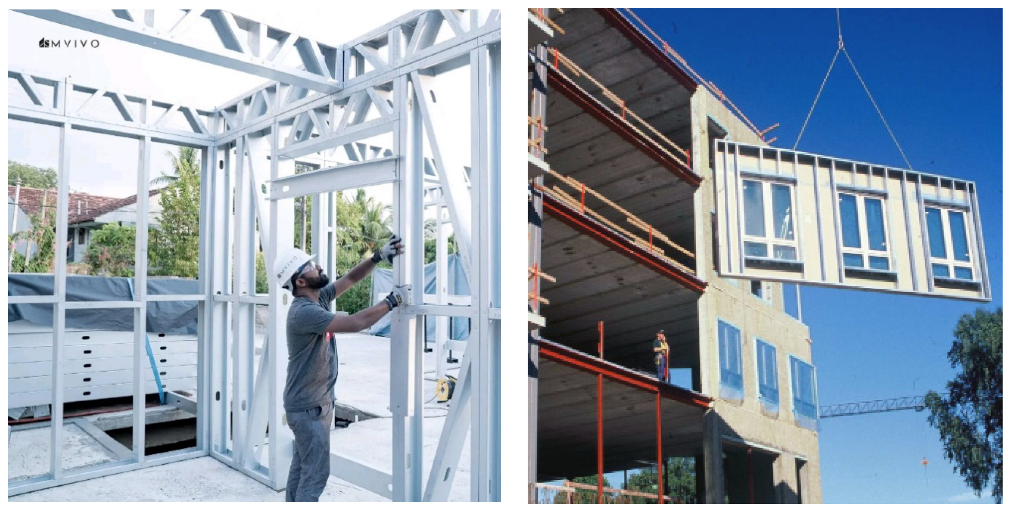
Cold-formed steel buildings utilize three distinct construction methods: stick-built construction, panelized modular elements, and volumetric modular elements. In stick-built construction, prefabricated cold-formed steel members are transported to the construction site as individual elements. The structure is then assembled and constructed on-site, as depicted in
Figure 1a. On the other hand, panelized elements and volumetric elements are constructed within a controlled factory environment. They are then transported to the site either as partially completed or fully completed units.
Figure 1b illustrates the transportation of partially completed panels, while
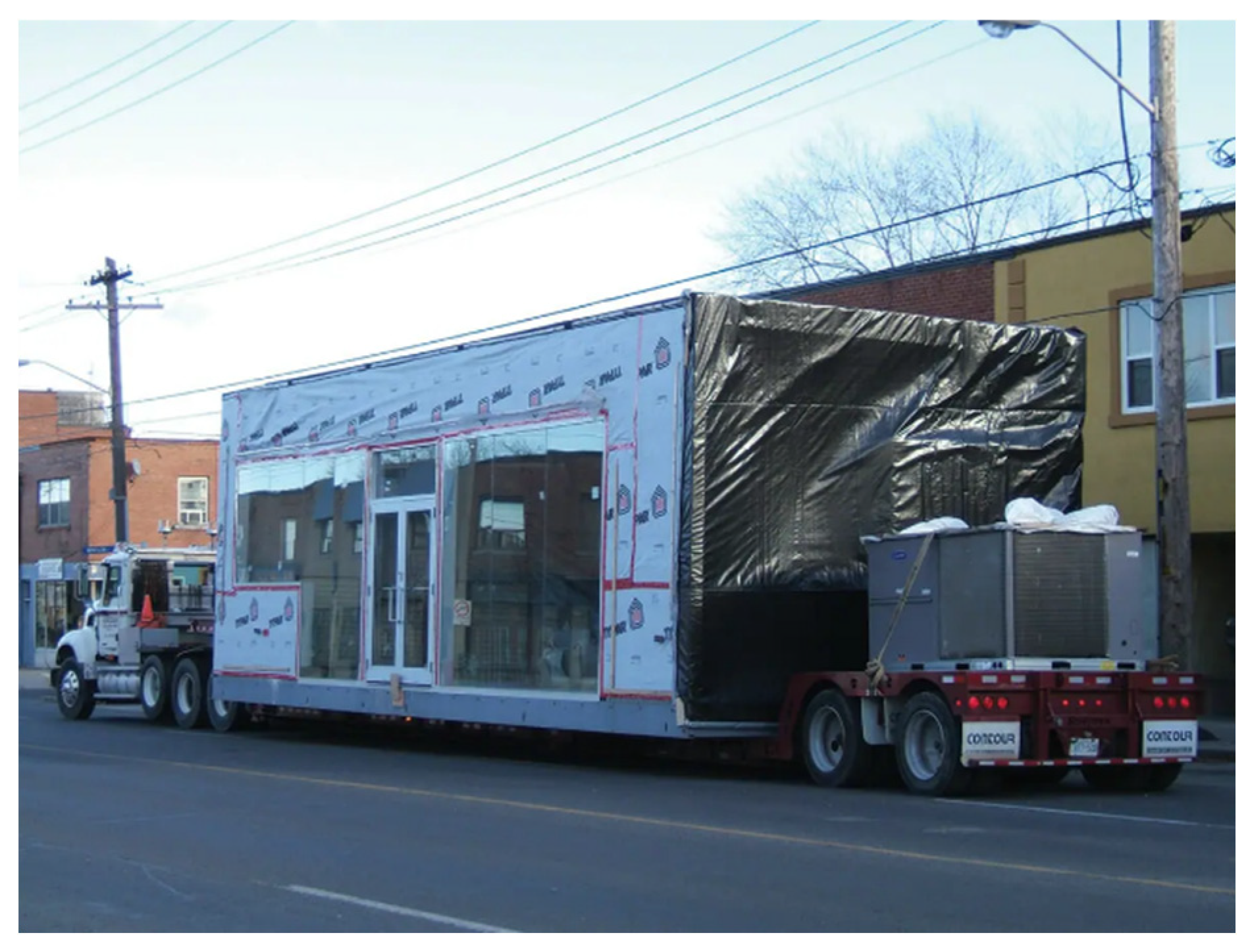
Figure 2 showcases the transportation of a partially completed volumetric modular unit.
Due to the state of transportation networks and the presence of unplanned residential settlements, transporting prefabricated components can pose challenges within the Sri Lankan context. In light of these factors, for the construction of MVIVO Homes in Sri Lanka, prefabricated studs were assembled on-site using the stick-built technique [
9]. However, it is worth noting that the factory-based construction and transportation of partially or fully completed units also remain viable options after considering the aforementioned factors.
Figure 1.
(
a) Stick-built construction adopted by MVIVO; (
b) Prefabricated curtain wall installed adapted from [
10].
Figure 1.
(
a) Stick-built construction adopted by MVIVO; (
b) Prefabricated curtain wall installed adapted from [
10].
Figure 2.
Fully fabricated modular unit with partial finishing transported to the site adapted from [
11].
Figure 2.
Fully fabricated modular unit with partial finishing transported to the site adapted from [
11].
2.1. Cold formed steel
Cold-formed steel presents an appealing construction alternative due to its lightweight nature, high weight-to-strength ratio, mass production capabilities, and ease of use both in factory settings and on-site [
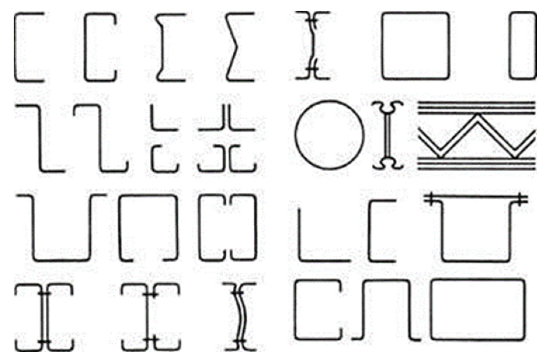
12]. To produce cold-formed steel (CFS) members, graded structurally sound steel sheets are rolled using a forming machine to achieve the required shapes, without the need for heat as in the case of hot-rolled steel. The thickness of these members can vary depending on their structural or non-structural purpose, ranging from 0.01 mm to 7 mm.
Figure 3 illustrates typical cold-formed sections commonly employed in both structural and non-structural applications.
The practical feasibility of various sections formed by rolling the sheet into different shapes is influenced by the capacity of commercially available machines [
13,
14,
15]. Building codes [
16] permit the use of load-bearing members with different steel grades, ranging from G250 (yield strength of 250 MPa) to G550 (yield strength of 550 MPa). However, due to cost considerations, the industry often opts for higher-grade steel like G550. Although the use of G550 steel initially emerged in the Australian construction industry for structural applications [
17], it has now become prevalent worldwide.
The utilization of high-strength steel such as G550 offers designers the advantage of reducing the steel thickness, consequently lowering the overall weight of steel used in construction. G550 steel is commonly employed as structural steel in construction projects, typically ranging in thickness from 0.42 mm to 1.50 mm [
18]. In our case in Sri Lanka, we have utilized 1.20 mm thick and 0.8 mm thick G550 steel in conforming to AS1397 [
19]. As per the manufacturer’s recommendation and tested results, the G550 steel provided a minimum yield stress of 550 MPa at ambient temperature. The behavior of high-strength steel grades such as G450 and G550 can be observed in studies conducted elsewhere [
20]. In all the Sri Lankan residential projects that were undertaken by MVIVO used G550 steel.
2.2. Cold formed steel coatings
Various coating methods are employed to protect steel from corrosion. Popular options include anodizing, galvanizing, powder coating, painting, epoxy coating, and duplex coating [
21]. Among these methods, galvanization is the most commonly used coating technique for cold-formed steel (CFS). Codes such as BS EN 10346 [
22] and AS 1397 [
19] provide coating requirements for structural elements used in construction. These codes recommend that zinc-coated elements be dipped in 99% pure zinc to achieve coatings defined as Z100 to Z600. The letter “Z” indicates the zinc coating, while the numbers 100, 200, 275, and 600 represent the weight of the coating. In the UK, a preferred zinc coating for CFS residential buildings is Z275, and similar preferences are observed in Australia. Sri Lanka, adopting Eurocode, may adhere to similar coating requirements.
In 1972, the Bethlehem Steel Corporation introduced a coating called “Galvalume,” which consists of 55% aluminum, 43.5% zinc, and 1.5% silicon [
23]. It has been observed that Galvalume steel exhibits better durability in coastal and marine environments and demonstrates improved heat resistance compared to zinc-coated steel [
23]. In Sri Lanka, CFS houses constructed using cold-formed steel typically employ Z275 or AZ150 coatings to ensure the durability of the structures. A review of the durability of cold-formed steel structures [
21,
24] has shown that structures with Z275 or AZ150 coatings have the potential to withstand a design life of 200 years.
3. Design Philosophy
Design of residential building using cold formed steel is relatively new to the Sri Lankan industry. As Sri Lanka adopts Eurocode with inclusion of local annexures, designs are generally governed by Eurocode. Therefore, BS EN 1993 – Part 1.3 [
25]was referred during the design stages along with AS 4600 [
16], which proves to be efficient for designers in design procedures.
3.1. Loads
Permanent actions and variable actions were determined according to BS EN 1991 [
26].
Table 2 lists all unfactored associated permanent and variable actions considered for the design. The loads were subsequently adjusted using the design factors specified for the ultimate design state in accordance with BS EN 1990 [
27].
3.2. Design of roof and floor joists
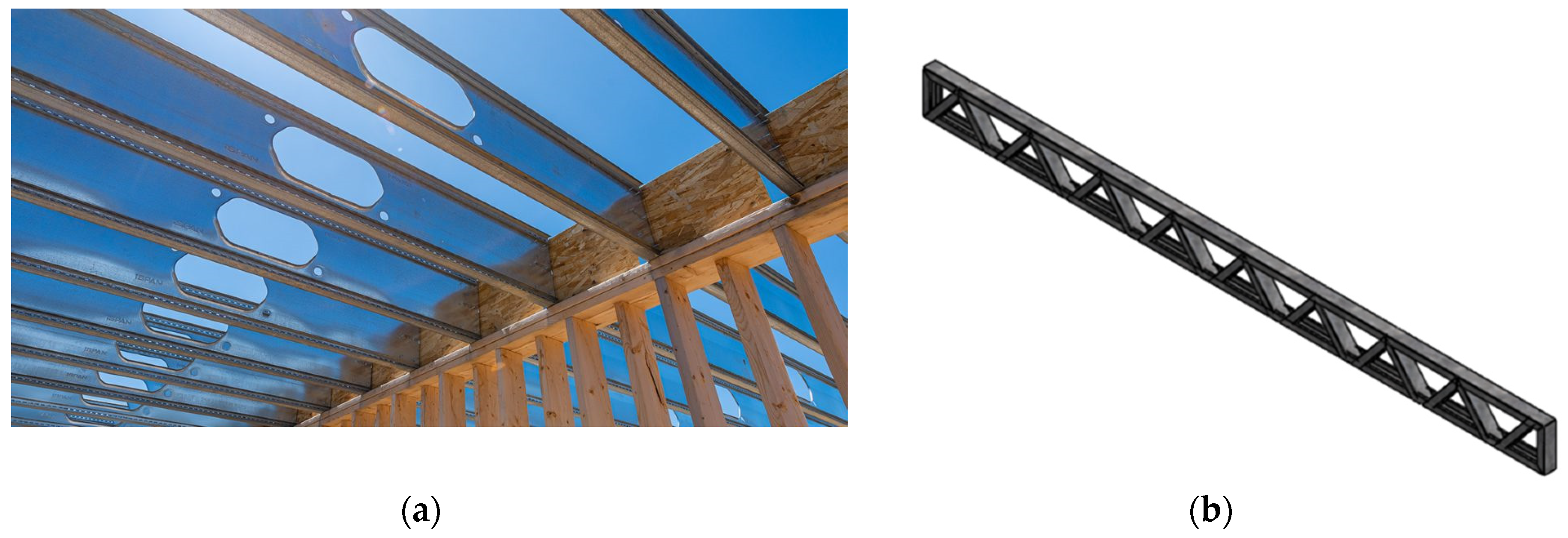
CFS structures can be designed using either a lipped C purlin as a floor/roof joist or a CFS truss as the joists. However, due to their higher width-to-thickness ratio, lipped C purlins made of cold-formed steel are prone to failure modes such as local buckling, distortional buckling, or global buckling. Designing to prevent failure in lipped C purlin beams often necessitates a reduction in span. To address this challenge, a decision was made to develop a CFS truss using lipped C sections. This approach provides sufficient bending capacity while offering flexibility to designers to achieve desired spans and extend design limits.
Figure 4 illustrates the two types of joists commonly used in CFS residential construction, with
Figure 4b being the adopted configuration in residential buildings constructed in Sri Lanka. For CFS trusses, 90 mm × 50 mm × 15.8 mm lipped C sections with a thickness of 1.2 mm were utilized.
3.3. Load bearning wall frames
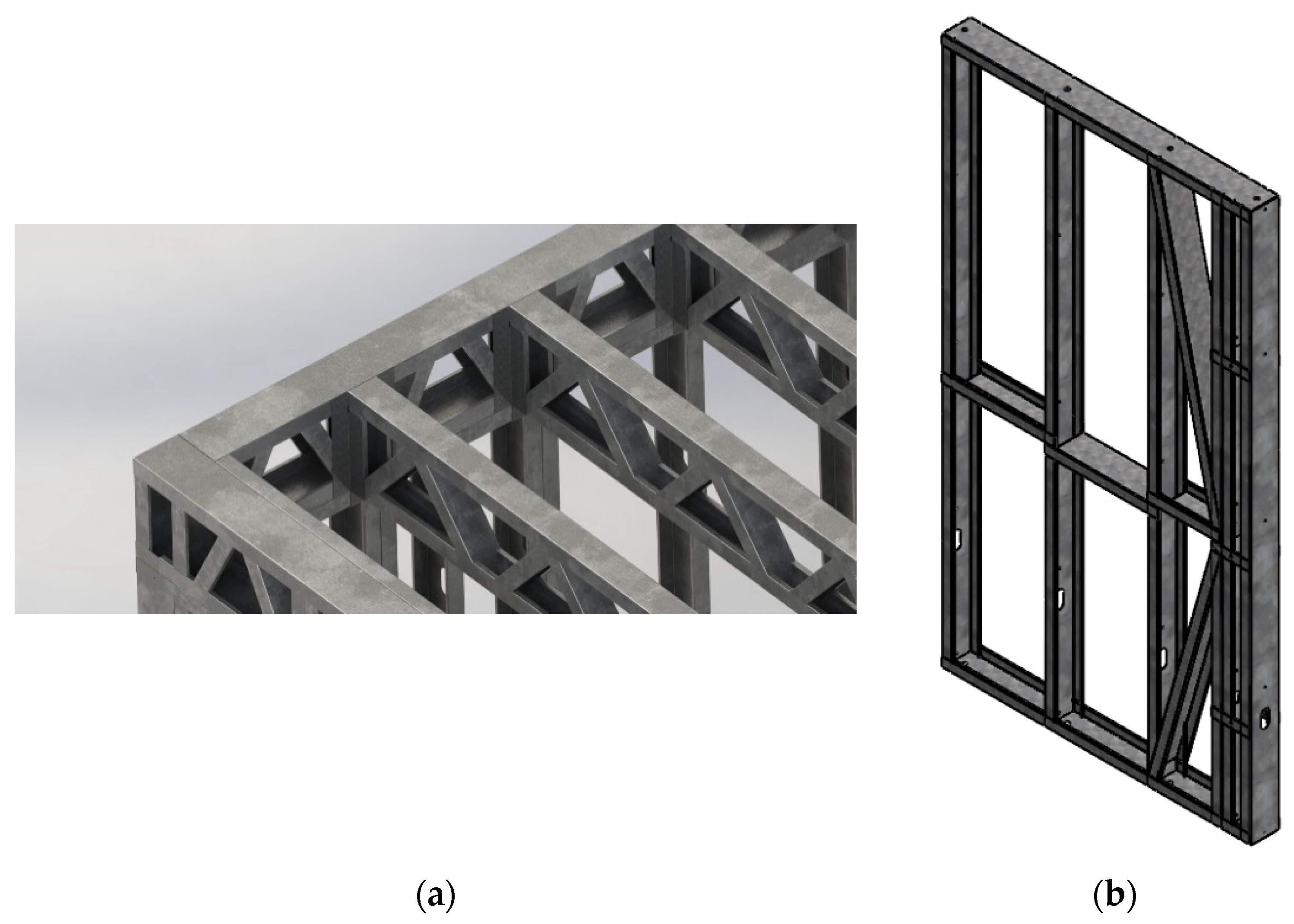
The design of CFS load-bearing walls took into account the external loads transferred from the joists onto the walls. This transfer of loads was facilitated by an innovative system of ring beams, as depicted in
Figure 5a. The ring beams serve to evenly distribute the load from the joists to the wall panels, ensuring structural integrity and stability.
The wall panels consisted of a 140 mm × 47 mm × 9.5 mm cold formed steel of 0.8 mm thickness in the middle and a oriented strand board (OSB) on the outer side and medium density board or plasterboard inside providing lateral restraint. Previous studies on CFS wall frames with gypsum sheathing [
28] and plasterboard sheathing [
29] demonstrated that the load carrying capacity of a CFS stud in a wall was much higher than the load carried by a single unrestrained CFS stud. Based on the design loads transferred to the wall frame, the wall frames were checked for their design resistance to carry the transferred load. The wall stud capacities were established using direct strength method (DSM) given in AS 4600 [
16]. The estimated capacities of the CFS stud were compared with the required resistance considering the stud without any sheathing. This ensured that the wall frames possess strength excess of the required resistance in wall studs.
Several types of standard wall frames were developed to provide flexibility of fabricating a required building using several wall frames. These frames included blind wall frame, door frame, window frame, utility frame, etc. A typical edge blind wall frame is shown in
Figure 5b with bracing for lateral wind load.
3.3.1. Wall panel composition
Traditional construction methods in Sri Lanka often rely on burnt bricks, stabilized earth blocks, and cement blocks. While these methods are familiar to the engineering community and relatively cost-effective, they may not possess the necessary attributes to compete in the modern world, which places significant importance on the energy intensity of production and maintenance.
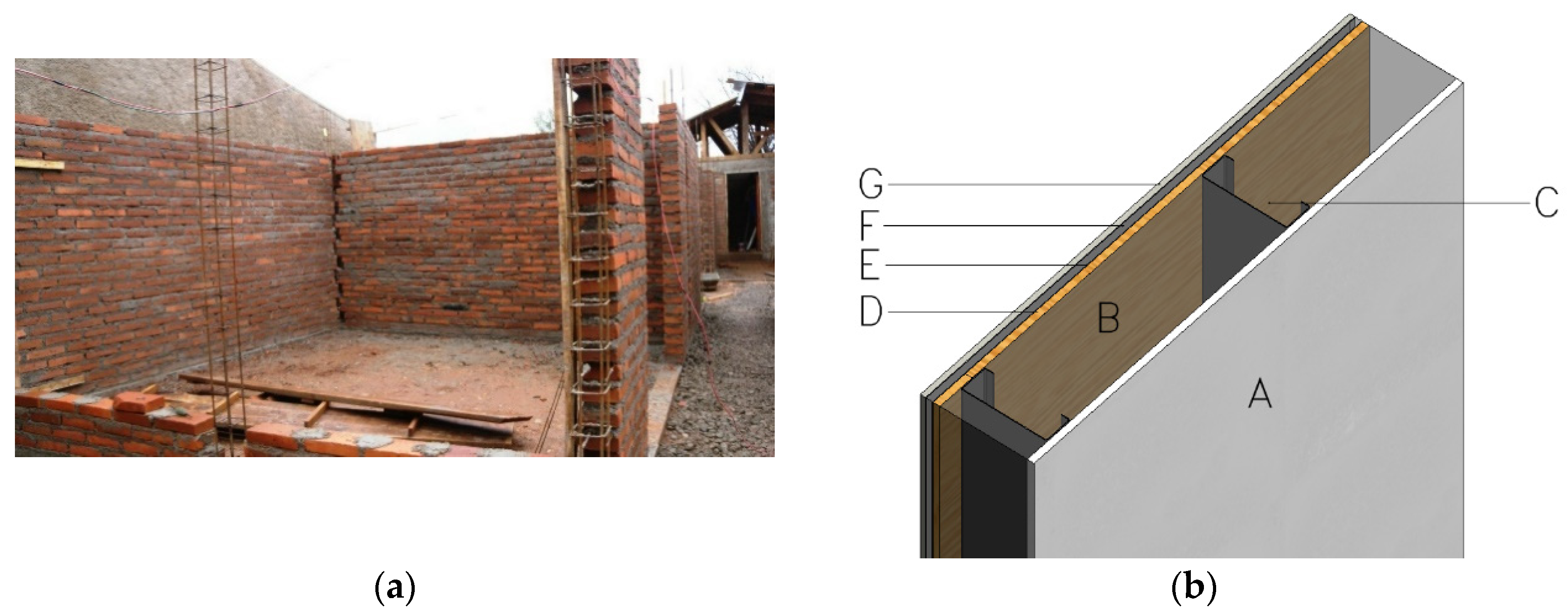
In the case of traditional burnt brick or cement block walls, the construction involves assembling block or brick elements using cement mortar as the primary material (see
Figure 6a. In many cases, plastering is applied to achieve the desired finished surface before any painting work is undertaken.
In contrast to traditional brick or cement block walls, modern composite walls are constructed with multiple layers of materials that offer enhanced strength, better sound insulation, and improved thermal resistance. In cold-formed steel structures, a crucial component is the steel stud positioned at the center of the wall, serving as a load-bearing element (refer to
Figure 6b). The voids within the wall are then filled with insulative materials like rock wool, and the inner side is covered with a cladding material, typically a medium density board, high density board, or gypsum board.
However, the external surface of the composite wall requires a combination of materials to create a barrier against water, vapor, and air.
Figure 6b illustrates the composite layer arrangement typically found and used in Sri Lankan projects for external walls.
3.3.2. Strength of wall panels
Design codes provide recommendations for the minimum compressive strengths of brick and cement block masonry units. The Australian code [
24] suggests a minimum compressive strength of 3.0 MPa for vertically cored blocks and solid blocks to be considered satisfactory. Similar recommendations can be observed for cement blocks as well. However, CFS walls take a different approach.
In CFS structures, the vertical load is supported by members such as C purlins, lipped C purlins, or sigma purlins, depending on the designer’s choice and the availability of production facilities. Various cold-formed steel manufacturing systems utilize computer-aided design (CAD) and computer-aided manufacturing (CAM) capabilities to produce complete housing structures [
13,
14,
15]. Some systems can produce lipped C purlins, and others have the ability to manufacture grooved (or stiffened) lipped C purlins. The vertical cold-formed sections are braced to resist lateral loads and further reinforced by sheathing materials and internal boards.
Similar to other steel elements, the critical behavior of CFS sections is predominantly governed by compression. The process of establishing the compression capacity is described in detail by AS 4600 [
16] and Eurocode 3 [
30]. Due to their high width-to-thickness ratios, most CFS sections fall into Class 4. Therefore, Eurocode 3 requires the calculation of effective width and the determination of strength for design purposes.
4. Durability Review
4.1. Review of data available in literature
Durability has been a major concern when developing CFS buildings for potential clients. Although there are no existing durability studies within Sri Lankan context, the available literature and case studies can help to evaluate the durability characteristics of CFS under various environmental conditions. Studies performed by National Association of Home Builders (NAHB) [
31], Baxter [
32], Way et al. [
33] and Williams et al. [
34] can help to assess the durability of CFS building under different exposure conditions.
4.1.1. Durability case study 1: Galvanized Steel Framing for Residential Homes [31]
Four test sites were selected by NAHB Research Center to study the corrosion performance of cold formed steels with different types of coatings. The location, environment of the site, type of the foundation ad exterior finish details is given in
Table 3 (Site No 1 – 4).
4.1.2. Durability case study 2: Environmental and Performance of light steel framing building [32]
One of the earliest light steel frame buildings constructed in 1982 was investigated and reported by Baxter (1990). This Ullenwood building was monitored for five years using galvanized and mild steel test specimen kept inside the wall and loft space. The structure was exposed to oceanic climate with warm summer and cool winter. Baxter (1990) reported the loss in galvanized steel was 0.2g/m
2 per year where mild steel was observed having a mass loss of 1.26 – 1.62 g/m
2. The data is shown in
Table 3 (Site No 5).
4.1.3. Durability case study 3: Student Accommodation Building at Oxford Brookes University [33]
A demonstration project constructed in 1996 at Oxford Brookes University was investigated for corrosion performance and reported by Way et al. The site is located in the city of Oxford about 1 km from a river. The study indicated that the depletion of the coating layer was minimal after 5 years when the loss of the coating material was observed between 5- and 10-year period. The study also indicated that the loss of coating mass was significantly higher when they were directly exposed to environmental conditions. The detail of the site is given in
Table 3 (Site No. 6).
4.1.4. Durability case study 4: Lisbon Technical University [33]
Way et al. reported a study conducted at Lisbon Technical University in Portugal. The site was exposed to hot coastal environment and the samples monitored were kept outside covered by cladding panel on the wall providing an environment of cold air constantly. The surface protection loss was estimated after 5- and 10- year period. The observation indicated the reduction of coating reduces with time as the loss of coating after 5 year period was 1.61 g/m
2 compared to a loss of 2.22 g/m
2 after 10 years. The detail of the site is given in
Table 3 (Site No. 7).
4.1.5. Durability case study 5: Study on coated fasteners by University of Hawaii [34]
The University of Hawaii carried out a study on the corrosion resistant nature of zinc coated fasteners and elements. Field enclosures representing actual residential buildings constructed for different exposure conditions were kept at different locations. The climatic conditions are like tropical and exposure to coastal environment that may mimic the conditions of the coastal Sri Lanka as well. The fabricated enclosures were located within 230 m to 1000 m from the coastal line. In each location total climate data was recorded. Details of the site is given in
Table 3 (Qualitative observations made at this site are given in
Table 3 (Site No. 8)).
Quantitatively assessed data from seven sites (Site 1 – 7) and qualitative data from one site (Site 8) are compared in
Table 4. It can be noticed that the data covers a wide range of climatic and environmental conditions to which the samples were exposed. Among the sites discussed, Miami, Florida (Site 1) and Oahu Island, Hawaii (Site 8) can be considered closely related to coastal area of Sri Lanka while Ullenwood, England can be considered as a climatic condition that may moderately represent hill country of Sri Lanka.
The quantitative data given in
Table 4 in general represent the most critical exposure conditions. For example, at site no.5, the critical data was observed inside the wall and loft. Considering most of the critical values, some of the experimental data were obtained from the literature are not presented in order to make a impactful outcome considering Sri Lankan scenario.
Exposure duration and mass loss were recorded by relevant authors [
31,
32,
33,
34]. Corrosion rate was calculated using the method given in ASTM G1-03 [
35]. Equation (1) can be used to determine the corrosion rate in galvanized steel elements.
Where,
K = constant = 8.76 X 107 μm/year
W = mass loss in grams
A = area in cm2
T = time of exposure in hours
D = density in g/cm3, a value 7.13 g/cm3 was assumed for zinc, 6.7 g/cm3 was assumed for Galfan, 3.75 g/cm3 was assumed for Galvalume.
Corrosion rates shown in
Table 4 were calculated using the Equation (1). Site 1 to 4 have used three different types of coating namely galvanized, Galvalume and Galfan. Galvanized coating is applied by dipping the steel inside 99% zinc to achieve the coating. There are two thicknesses that were used. Some samples have used 38 μm thick coating while some have used 29 µm coating. Durability is proportional to the thickness of the coating [
24]. Therefore, the thicker the coating, the better the protection. As discussed earlier, Galvalume is a composition developed using 55% Aluminum, 43.5% Zinc and 1.5% silicon. If thickness of the coating is considered, Z275 coating (99% zinc 275 g/m2) and AZ150 (Galvalume 150 g/m2) provide the same thickness of 20 µm. The Galfan coating is a composition using 95% Zinc, 5% Aluminium and 0.05% mischmetal [
36]. It can be observed from the data recorded on similar environmental conditions that galvanized elements demonstrate better resistance to corrosion than Galvalume and Galfan. The data recorded at Hamilton, Ontario show that Galfan shows better resistance than Galvalume in cold and industrial areas. However, conventional galvanized coating indicates a comparable corrosion resistance like Galfan.
4.2. Corrosion observations in structures
The wall area can fall into two categories. The first category is a well-protected wall like the one shown in
Figure 6b. The well protected wall area will have a lower level of humidity and dry environment to achieve a higher level of insulative properties. In modern buildings, a thermal conductivity in the range of 0.06 W/(m.K) is expected to meet the stringent energy guidelines [
24]. Therefore, the walls in general will have a well-sealed environment that reduces humidity and wetness.
Galvanized wall elements record a corrosion rate of 0.028 – 0.035µm/year under different climatic conditions. The rate of corrosion further reduces when the data is obtained for a longer duration as observed from
Table 4. It can be also observed that there is no significant difference between cold wall environment and warm frame environment. Lawson et al. [
24] proposed an equation that can be used to determine the design life of a cold formed steel element based on the exposure conditions. It was argued that for elements that are in concealed environments to be assumed to have reached the service life once 50% of zinc coating is lost. In cases where the cold formed steel elements were visible and easy to inspect, the service life can be determined based on 80% loss of the zinc coating. The following equations (Equation 2 and Equation 3) were proposed by Lawson et al. to estimate the design life of cold formed steel elements. Equation 2 can be used for concealed steel elements and equation 3 can be used for exposed and visible elements.
Design life calculated using equations (2) for wall, attic and loft spaces and the same calculated for exposed members such as below ground floor area using equation (3) by the authors are listed in
Table 4.
Like walls, attic and loft areas under an enclosed environment, spaces show reduced corrosion rates. However, exposed steel such as CFS below ground floor have seen a significant increase in corrosion rate as shown in Figure 8. A lower rate for upper part of a wall was noticed while during the same period a 6 times higher rate was observed for exposed steel below ground floor.
5. Conclusions
Cold-formed steel buildings serve as an alternative to timber stud construction due to the inherent durability of steel. They also offer an energy-efficient and cost-effective alternative to reinforced concrete, masonry, and brick construction. In comparison to concrete, brick, and timber, steel is considered the least environmentally damaging material in terms of energy consumption and pollution [
37]. Furthermore, steel is highly recyclable, making it one of the most efficient recycled materials available.
The scarcity of conventional construction materials like brick and concrete has prompted designers and engineers to explore alternative materials for construction purposes. Given that building maintenance contributes significantly to global energy demand [
7], it is crucial to consider alternatives that conserve energy while offering greater flexibility for reuse and recycling.
The CFS residential buildings discussed in this paper were constructed using several reusable and recyclable materials. Except the foundation, which was made of concrete through a combination of a pad footing and a waffle slab, all other elements of the residential building are either reusable or recyclable. Taking into account the significant environmental and social benefits associated with CFS buildings, the following conclusions can be drawn.
Cold-formed steel (CFS) elements can be easily constructed using cold forming machines once the design is completed. The entire load-bearing elements can be produced within a period of 4-5 days, significantly reducing construction time.
Design codes for CFS buildings, such as BS EN 1993 and AS 4600, have well-established methods for determining the capacity of CFS elements. These codes provide designers with access to methods and procedures to adopt when designing CFS buildings. Therefore, if engineers are willing to choose CFS for residential construction, these codes can be used without much difficulty.
CFS buildings are often constructed using light gauge steel frames as load-bearing elements, with rockwool insulation in walls, floors, and roofs providing thermal insulation. Internal and external board materials serve as lateral restraints and cover for the structural steel. Steel and rockwool demonstrate a higher degree of reusability at the end of their service life. The board materials used in walls, floors, and roofs can be recycled or repurposed, minimizing waste generation. As a result, almost all building elements can be either reused or recycled without sending any waste to landfill.
CFS buildings constructed in Sri Lanka by MVIVO were designed using Building Information Modelling (BIM) up to the level of development 500 (LOD 500). This advanced level of design ensures that material usage in the building is planned in advance, reducing wastage. The incorporation of prefabricated elements, such as CFS, rockwool, and board materials, further reduces wastage during construction.
Literature has shown that galvanized and galvalume coated CFS members demonstrate exceptional durability, surpassing the required 50-year lifespan for residential buildings. Under various environmental conditions, the average durability of CFS steel kept inside covered wall or floor areas was observed to exceed 200 years. This indicates that the steel remains intact and reusable without significant deterioration.
Overall, CFS buildings offer an excellent alternative to concrete and masonry residential buildings due to their strength, serviceability, durability, and higher level of reusability or recyclability at the end of their service life.
Author Contributions
Conceptualization, G.T. and K.V.D.; methodology, G.T.; field data collection and literature data collection, G.T.; writing—original draft preparation, G.T.; writing—review and editing, G.T and K.V.D;
Data Availability Statement
Not applicable.
Acknowledgments
Support of MVIVO (Pvt) Ltd. to collect data is highly appreciated.
Conflicts of Interest
The authors declare no conflict of interests.
References
- UN Habitat Housing. United Nations Human Settlements Programme 2023.
- ACI Framing Material Use in Residential Construction: An Investigation of the Factors Influencing Framing Material Choice in Residential Building; Forest Wood Products Australia: ACT, Australia, 2018;
- NAHB, R.C., Inc How Many Homes Are Concrete-Framed? Eye on Housing 2020.
- Hurmekoski, E. Long-Term Outlook for Wood Construction in Europe. Diss. For. 2016, 2016. [CrossRef]
- Mayouf, M.; Jones, R.; Ashayeri, I.; Nikologianni, A. Methods of Construction to the Meet Housing Crisis in the UK Residential Sector: A Comparative Study between Timber Frame and Masonry Construction. Buildings 2022, 12, 1177. [CrossRef]
- Nature Concrete Needs to Lose Its Colossal Carbon Footprint. Nature 2021, 597. [CrossRef]
- 2018; 7. Global Alliance for Buildings and Construction; United Nations Environment Programme 2018 Global Status Report; 2018;
- Vivian W.Y., T. Rate of Reusable and Recyclable Waste in Construction. TOWMJ 2011, 4, 28–32. [CrossRef]
- MVIVO Stick-Built Construction.
- Veljkovic, M.; Johansson, B. Light Steel Framing for Residential Buildings. Thin-Walled Structures 2006, 44, 1272–1279. [CrossRef]
- Modular Building Institute Modular vs. Stick Built and A Case for the Future of Construction.
- Yu, W.-W. Cold-Formed Steel Structures; 1999;
- PinnacleLGS Inc Pinnacle LGS 2023.
- FRAMECAD Why FRAMECAD.
- Steel Framing Systems | Light Gauge Steel | Cold Formed Steel | Scottsdale Available online: https://www.scottsdalesteelframes.com/steel-framing-solutions (accessed on 4 July 2023).
- AS/NZS 4600 Cold-Formed Steel Structures; Standards Australia, GPO Box 476, Sydney, NSW 2001, 2018;
- Rogers, C.A.; Hancock, G.J. Ductility Measurements of Thin G550 Sheet Steels.; Missouri, USA, 1998.
- Zhao, J.; Yu, C. Experimental Study and Numerical Simulation of G550 High Strength Cold-Formed Steel Z-Section Members Under Pure Bending and Moment Gradient. Int J Steel Struct 2019, 19, 366–380. [CrossRef]
- Standards Australia AS 1397-2011: Continuous Hot-Dip Metallic Coated Steel Sheet and Strip - Coatings of Zinc and Zinc Alloyed with Aluminium and Magnesium; Standards Australia: Sydney, Australia, 2021;
- Gunalan, S.; Bandula Heva, Y.; Mahendran, M. Local Buckling Studies of Cold-Formed Steel Compression Members at Elevated Temperatures. Journal of Constructional Steel Research 2015, 108, 31–45. [CrossRef]
- Cooray, K.; Tharmarajah, G. Durability of Cold Formed Steel Structures Used in Residential and Industrial Construction.; SLIIT: Colombo, Sri Lanka, 2023.
- BSI BS EN 10346: Continuously Hot-Dip Coated Strip and Sheet of Structural Steels. Technical Delivery Conditions; London, Great Britain, 2006;
- Coni, N.; Gipiela, M.L.; D’Oliveira, A.S.C.M.; Marcondes, P.V.P. Study of the Mechanical Properties of the Hot Dip Galvanized Steel and Galvalume®. J. Braz. Soc. Mech. Sci. & Eng. 2009, 31, 319–326. [CrossRef]
- Lawson, R.M.; Popo-Ola, S.O.; Way, A.G.; Heatley, T.; Pedreschi, R. Durability of Light Steel Framing in Residential Applications. Proceedings of Institution of Civil Engineers: Construction Materials 2010, 163. [CrossRef]
- BSI BS EN 1993-1-3 2004.
- BSI BS EN 1991-1. Eurocode 1: Acions on Structures - Part 2: Traffic Loads on Bridges 2003.
- BSI BS EN 1990: Basis of Structural Design 2002.
- Miller, T.H.; Pekoz, T. Behavior of Gypsum-Sheathed Cold-Formed Steel Wall Studs. J. Struct. Eng. 1994, 120, 1644–1650. [CrossRef]
- Telue, Y.; Mahendran, M. Behaviour of Cold-Formed Steel Wall Frames Lined with Plasterboard. Journal of Constructional Steel Research 2001, 57, 435–452. [CrossRef]
- Eurocode 3. Design of Steel Structures: General Rules; BSI British Standards;
- NAHB Research Center, Inc Galvanized Steel Framing for Residential Buildings; American Iron and Steel Institute (AISI) Specifications, Standards, Manuals and Research Reports (1946 - present)., 2006;
- Baxter, C.A. Environmental and Performance Monitoring of PMF Ltd. Steel Framing Building at Ullenwood - Five Year Test Results; British Steel Welsh Technology Centre: Wales, 1990;
- Way, A.G.; Popo-Ola, S.O.; Biddle, A.R.; Lawson, R.M. Durability of Light Steel Framing in Residential Applications; The Steel Construction Institute: Berkshire, U.K, 2009;
- Williams, L.; Moody, D.; Larson, J. Corrosion of Galvanized Fasteners Used in Cold-Formed Steel Framing; American Iron and Steel Institute: Honolulu, HI, 2006;
- G01 Committee Practice for Preparing, Cleaning, and Evaluating Corrosion Test Specimens; ASTM International, 2017;
- Yoo, Y.R.; Choi, S.H.; Kim, Y.S. Atmospheric Corrosion Behavior of Carbon Steel by the Outdoor Exposure Test for 10 Years in Korea. Corrosion Science and Technology 2022, 21, 184–199. [CrossRef]
- Tian, Y.S.; Wang, J.; Lu, T.J. Axial Load Capacity of Cold-Formed Steel Wall Stud with Sheathing. Thin-Walled Structures 2007, 45, 537–551. [CrossRef]
|
Disclaimer/Publisher’s Note: The statements, opinions and data contained in all publications are solely those of the individual author(s) and contributor(s) and not of MDPI and/or the editor(s). MDPI and/or the editor(s) disclaim responsibility for any injury to people or property resulting from any ideas, methods, instructions or products referred to in the content. |
© 2023 by the authors. Licensee MDPI, Basel, Switzerland. This article is an open access article distributed under the terms and conditions of the Creative Commons Attribution (CC BY) license (http://creativecommons.org/licenses/by/4.0/).
