1. Introduction
The customizability of chemical synthesis enables the creation of new molecules and the demonstration of structure-property relationships. Rationally, any molecule can be obtained through rational design and chemical synthesis. However, due to the cumbersome process and other objective factors, the process was not smooth sailing. On this basis, crystalline molecules with long-range order are unique. This is because the discrete molecular spaces or interfaces provided by crystalline molecules can effectively trigger and control the interactions between various molecular systems. If individual small molecules are integrated in an orderly manner, not only a new organic material can be created, but also new functions and properties can be expanded. Since Yaghi realized the preparation of covalent organic frameworks (COFs) by self-condensation and co-condensation of the monomers with multiple reaction sites in 2005, crystalline compounds with network-like chemistry have been rapidly developed [
1]. The network-like chemistry of covalent organic frameworks enables top-down design at the molecular level, leading to alignments guided by geometric structures [
1,
2,
3]. The advantages of such structural diversity and control over functions are perfectly reflected in COFs, which are widely used in fields such as gas storage [
4,
5], separation [
6,
7], catalysis [
8,
9,
10], optoelectronics [
11,
12,
13,
14], sensing [
15,
16,
17] and biological fields [
5,
18]. It is worth noting that the unique physical and chemical properties of COF materials are closely related to their crystal structures [
19,
20]. Therefore, a detailed determination of their atomic arrangement is crucial for understanding the structure-property relationship in order to obtain the desired application. The structural analysis of COFs is entirely dependent on single crystal; however, the growth of single crystal is closely related to the synthesis process of COFs.
Polycondensation is the main method widely used in polymers, which proceeds through a stepwise growth mechanism that produces materials with broad molecular weight distributions when intermediates of different lengths react with each other to form uncontrolled amorphous structures. The synthesis of COF also adopts the polycondensation method, with the difference that it introduces a reversible-coagulation strategy, which forms a new system to obtain crystalline two-dimensional/three-dimensional (2D/3D) compounds with primary chemical structures and high-order assembly structures-2D/3D COFs. Although it is possible to obtain crystalline COFs through the synthesis process of reversible polycondensation-coagulation, many cases have shown that it is still challenging to obtain sufficiently large (nanocrystal ≤ 50 nm) and ordered COF crystals for single crystal X-ray diffraction analysis due to the interplay of nucleation and crystal growth processes. It was not until 2018 that the Wang’s group prepared the first example of large-size single crystals that could be analyzed by single-crystal X-ray techniques using the aniline regulator strategy [
21]. However, this method cannot be further extended to other COF systems. In order to further expand the single-crystal system of COFs, researchers have been working on developing new methods. Currently, the seed method and monomer sustained release method have been developed, but they have not yet been successfully characterized by single crystal X-ray diffraction [
22,
23].
By far, single crystal X-ray diffraction is the most widely used method for structure determination. However, single crystal X-ray diffraction characterization is severely hindered by issues such as the small crystal size and poor crystal quality of COFs. Therefore, there is currently a lack of effective means to determine its structure. Although current simulations agree well with experiments, the diversity of crystal structures remains uncertain. Therefore, advancing the structural characterization of nanocrystalline powders is the key to overcoming the structure-activity relationship and developing new materials. Transmission electron microscopy (TEM) characterization techniques have been shown to be effective in determining the structure of nanocrystals [
24,
25,
26]. However, inorganic-organic hybrids and organic crystals tend to be more sensitive to the electron beam in the TEM than inorganic crystals and are prone to electron beam damage, which greatly limits data resolution and quality [
27,
28]. As a result, although many COFs have clear PXRD patterns, they cannot provide TEM crystallographic information or provide very poorly defined lattice fringes. Due to the intolerance of the electron beam, the fringe information of the crystal disappeared. To date, it has not been observed how the electron beam affects the stripes and how the electron beam destroys the stripes.
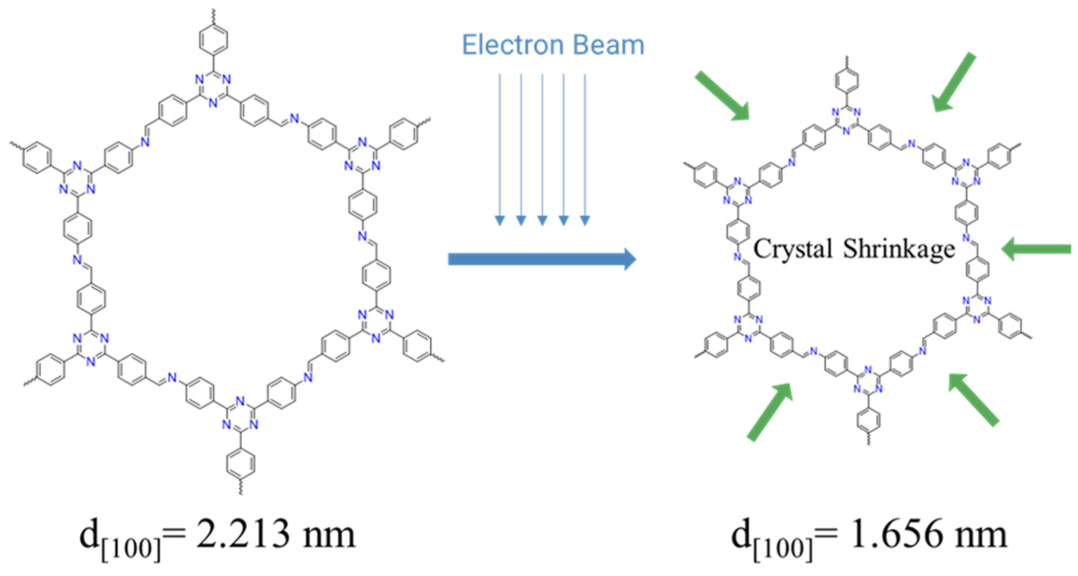
Herein, we report a case of lattice shrinkage induced by electron beam irradiation. Firstly, based on the unit cell size calculated by theoretical simulation and experimental PXRD data, we observed the crystal data of TAPT-TFPT COF under ordinary room temperature TEM and Cryo-electron microscopy (Cryo-TEM), respectively. The results are as follows: the lattice fringe corresponding to the 100 peaks of TAPT-TFPT COF crystal is approximately 2.213 nm; the crystal quality of TAPT-TFPT COF is poor (the lattice fringes are not clear and discontinuous), and the lattice fringes of the 100 peak shrink to 1.656 nm by conventional room temperature TEM. Observation by Cryo-TEM shows that TAPT-TFPT COF exhibits good crystal quality (clear lattice fringes and high continuity), and the lattice fringe of 100 peaks is 2.243 nm which is very close to the true size of 2.213 nm. To the best of our knowledge, this is the first observation of electron beam-induced lattice shrinkage in 2D-COFs. The lattice shrinkage caused by the electron beam is actually a certain destruction of the crystal structure by the electron beam. This provides a new idea and an improvement method for the structure determination of 2D-COFs.
Scheme 1.
Schematic diagram and chemical structures of the TAPT-TFPT COF lattice shrinkage under electron beam.
Scheme 1.
Schematic diagram and chemical structures of the TAPT-TFPT COF lattice shrinkage under electron beam.
2. Materials and Methods
Materials: The building block of 1,3,5-tris-(4-aminophenyl) triazine (TAPT) and 1,3,5-tris-(4-formylphenyl) triazine (TFPT) were purchased from Jilin Chinese Academy of Sciences -Yanshen Technology Co., Ltd. All chemicals and solvents were obtained from commercial sources without further purification.
Methods: TAPT-TFPA COF was synthesized by a modified solvothermal method. TAPT (20.00 mg, 0.056 mmol) and TFPT (22.20 mg, 0.056 mmol) into a 10 mL clean glass tube. Then a solvent mixture of dioxane: mesitylene = 1:1 (1.0 mL) was added and the mixture was sonicated for 5 min. It is worth noting that the monomer blocks cannot be completely dissolved here, which is not conducive to the growth of COF crystals. The high monomer content in the solution makes it easy to detonate, which will reduce the quality of crystals and reduce the size of crystals due to the numerous nucleation sites. At this point, the glass tube was filled with nitrogen (N2) and placed in liquid nitrogen to cool the solution system to be a solid. 0.1 mL of AcOH (6M) aqueous solution was added into the system subsequently the tubes were degassed by three freeze-pump-thaw cycles and sealed with a flame. After the system was warmed up to room temperature, the sealed tube was slowly heated to 120° C in a quiet oven and kept for 72 h. The precipitate formed was collected by filtration, washed with methanol and tetrahydrofuran (THF), and further activated by Soxhlet extraction with methanol and THF for 72 h to remove unreacted monomers and other impurities to obtain the freshly synthesized COF. Finally, the solid was collected and dried under vacuum at 120 °C for 12 h to obtain the bright yellow powder TAPT-TFPT COF (34.86 mg, 89.0%).
Instruments: X-Ray Powder Diffraction. PXRD patterns were recorded on PANalytical Empyrean diffractometer for Cu/Kα radiation (λ = 1.5416 nm). The samples were spread on the square recess of XRD sample holder as a thin layer. In order to rule out the effect of temperature on the lattice, the collection of PXRD patterns at different temperatures is necessary. On the basis of not changing any other conditions, the PXRD pattern was measured at different temperatures under the protection of N2. Sorption Measurements. Argon (Ar) sorption isotherms were measured at 87K using Autosorb-IQ instrument after samples were degassed at 120 °C for 8 h under vacuum. Pore size distributions of samples were determined by QSDFT. The Fourier transform infrared spectroscopy (FT-IR) spectra were collected using FT-IR spectrometer (VERTEX 70v) at vacuum. Solid State NMR. 13C cross polarization magic angle spinning nuclear magnetic resonance (13C CP/MAS NMR) spectra were recorded on a Bruker Avance III 400MHz spectrometer. Samples were packed in 4 mm ZrO2 rotors, which were spun at 8 kHz in a double resonance MAS probe. All spectra were background corrected. Transmission Electron Microscopy. We observe the same sample at different temperatures to explore the effect of the electron beam on the crystal structure. TEM images were acquired on JEM-2100 (200KV) and Themis 300 (Cryo-TEM) with an accelerating voltage of 200 KV, using low-dose techniques and the dose rate was <5.0 e/Å2/s. To avoid solvent damage to the crystal structure, TEM samples were prepared by dry powder. The powder is first lightly rubbed through two glass slides to form a finely divided powder, and then the microgrid is used to gently dip the powder on the glass slides. To prevent dipping into larger particles, tap your hand to make the larger particles fall. This method can not only obtain better samples for the transmission electron microscope, but also prevent large particle samples from falling into the vacuum chamber of the transmission electron microscope to contaminate the chamber.
3. Results
3.1. Crystal Structure of TAPT-TFPT COF
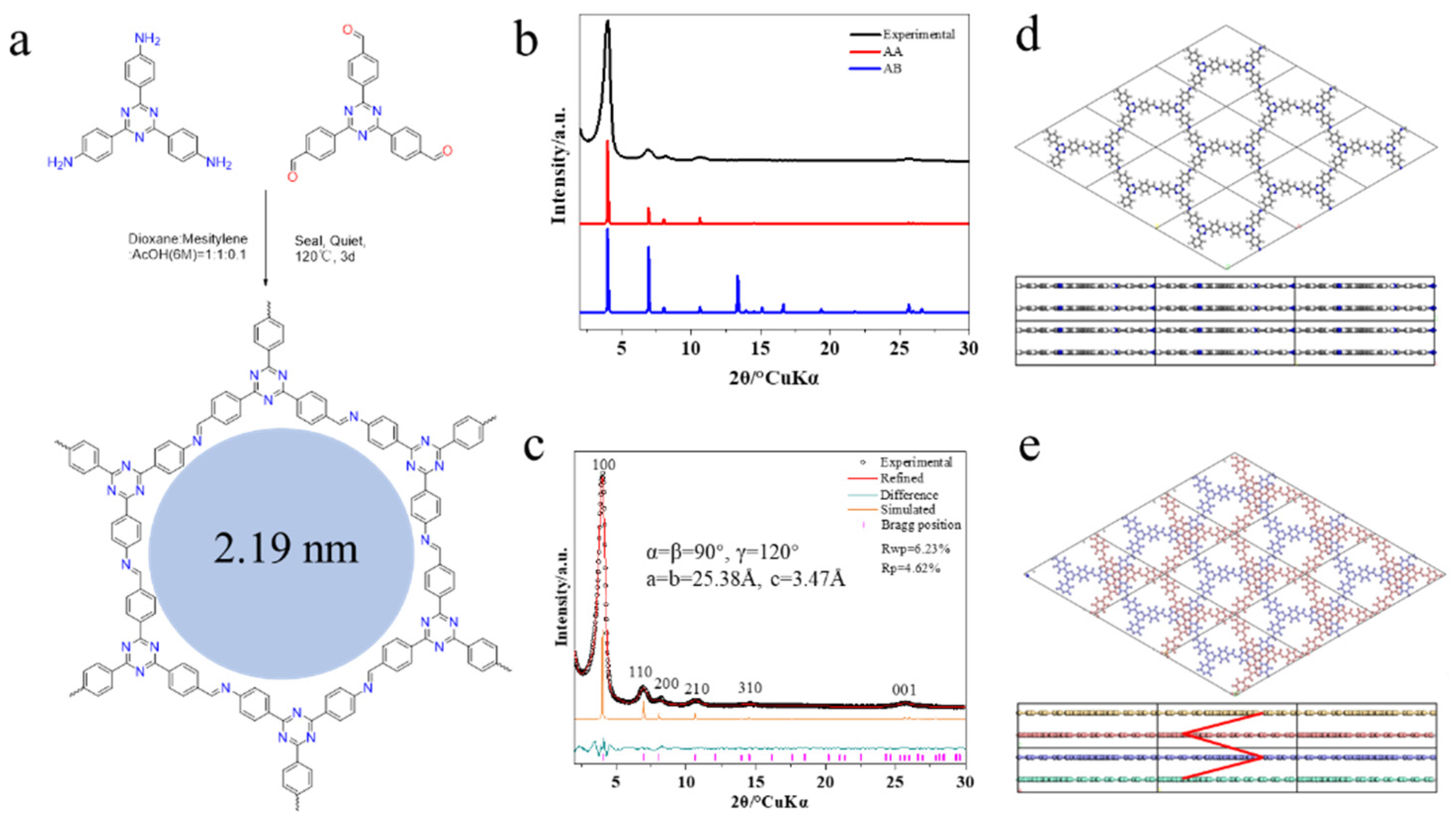
The TAPT-TFPT COF powders were successfully synthesized by a modified solvothermal reaction at 120 °C using TAPT and TFPT as the building blocks and a mixture of dioxane (DO)and mesitylene (MS) as the solvent (
Figure 1a). PXRD was used to determine the crystal structure of TAPT-TFPT COF. The PXRD pattern of TAPT-TFPT COF revealed sharp reflection peaks at 4.00 (100), 6.91 (110), 8.22 (200), 10.65 (210), 14.56 (310) and 25.64 (001), which agrees well with simulated data of P6-symmetric structure model (
Figure 1b,c), indicating the formation of AA-phase crystal. As we mentioned earlier, the current determination of the crystal structure of COF mainly relies on the comparison between the experimental PXRD pattern and the simulation results. The simulated AA and AB models of were shown in
Figure 1d,e. The way AA is stacked is that the upper and lower layers of COF do not slide relative to each other. The pattern of AB stacking is that two adjacent layers of COFs slide relative to each other, and the upper layer moves laterally to the middle of the hexagonal hole, that is, moves to the [1/3, 1/3] unit cell. The AA-stacked interlayer repeat unit is a monolayer, and the AB-stacked repeat unit is a bilayer. The unit cell parameters obtained from Pawley fitting were a = b = 25.38Å, c = 3.47Å, and Rwp = 6.23%, Rp = 4.62%.
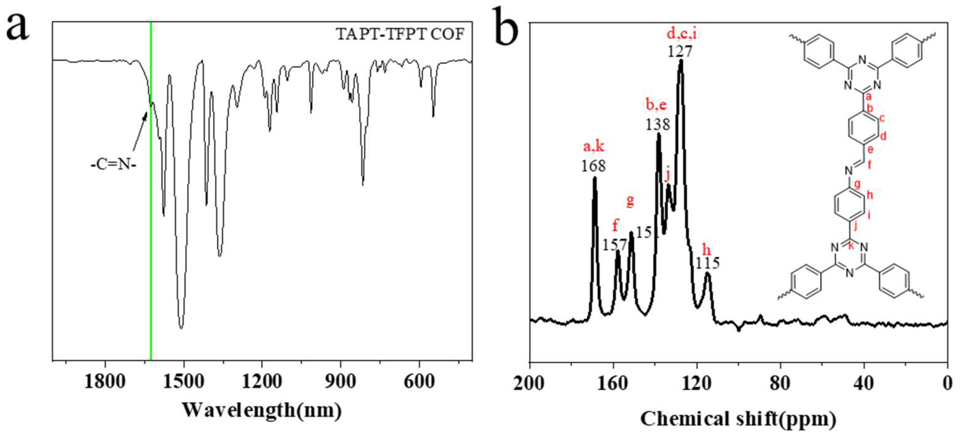
The same topological crystal structure can allow many chemical structures to exist at the same time. Therefore, after the crystal structure is confirmed, it is necessary to confirm the correctness of its chemical structures. Fourier transform infrared spectroscopy (FTIR) and
13C nuclear magnetic resonance (NMR) were used to characterize the TAPT-TFPT COF (
Figure 2). Disappearance of aldehyde carbonyl peak (1700cm
−1) and appearance of a new stretching signal at ~ 1624cm
−1 corresponding to the imine bond, which indicated that TAPT and TFPT were fully reacted to form the imine networks. On the other hand, signals of the corresponding carbon at 157 ppm (
13C) also indicate the formation of the imine bond. At the same time, we can clearly observe a well-defined peak instead of a fused broad peak, which indicates that the atoms of COF are in a relatively regular environment. This result indirectly indicates the better crystallinity of TAPT-TFPT COF, which corresponds to the good PXRD pattern of TAPT-TFPT COF. These data indicate the successful synthesis of high crystalline TAPT-TFPT COF powders [
29].
3.2. Argon absorption and desorption
COF materials are porous crystalline materials with porous structures and long-range periodic structures. Theoretically, the formation of the frame structure will inevitably lead to the formation of the hole structure. For the two-dimensional system, the hexagonal holes in the single-layer structure form the final 1D through-holes through the continuous stacking of layers. The change of the stack will inevitably change the pore structure and pore size. We deduce that TAPT-TFPT COF adopts the AA stacking mode through PXRD data and theoretical simulation. Absolute AA stacking (eclipsed) is unfavorable in energy, and slight sliding between layers is the stacking method with the lowest energy. The effect of this slight sliding on the PXRD pattern and pore size is basically negligible. Therefore, for the convenience of discussion, this article adopts the concept of AA stacking. The TAPT-TFPT COF theoretically has hexagonal through holes with a diameter of 2.19 nm. Hence, the Argon (Ar) adsorption-desorption curve was collected to determine the porosity of the synthesized TAPT-TFPT COF at 87K. TAPT-TFPT COF displayed a typical type IV(b) isotherms: the initial monolayer-multilayer adsorption on the mesoporous wall is the same as the corresponding partial path of type II isotherm, followed by condensation phenomenon in the channel, and then finally, the adsorption saturation plateau was reached. This result indicated that the framework network is microporous (
Figure 3a). TAPT-TFPT has direct open channels with relatively large adsorption capacity. At the same time, the adsorption curves did not show obvious hysteresis loops, and the close overlap of the adsorption and desorption curves further indicated the formation of 1D open holes in TAPT-TFPT COF. The pore size distribution calculated by quenched solid density functional theory (QSDFT) also further proves its 2.16 nm pore size, which is close to the theoretical value (
Figure 3b). The BET areas of TAPT-TFPT COF were determined to be 2009 m
2/g in the relative pressure range of 0.05–0.09 (
Figure 3c). When the relative pressure is less than 0.05, multi-layer physical adsorption cannot be formed, and even a single-molecule physical adsorption layer is far from being established, and the unevenness of the surface becomes prominent. When the relative pressure is greater than 0.09, the appearance of capillary condensation destroys the process of multilayer physical adsorption.
3.3. Crystal Characterization by TEM
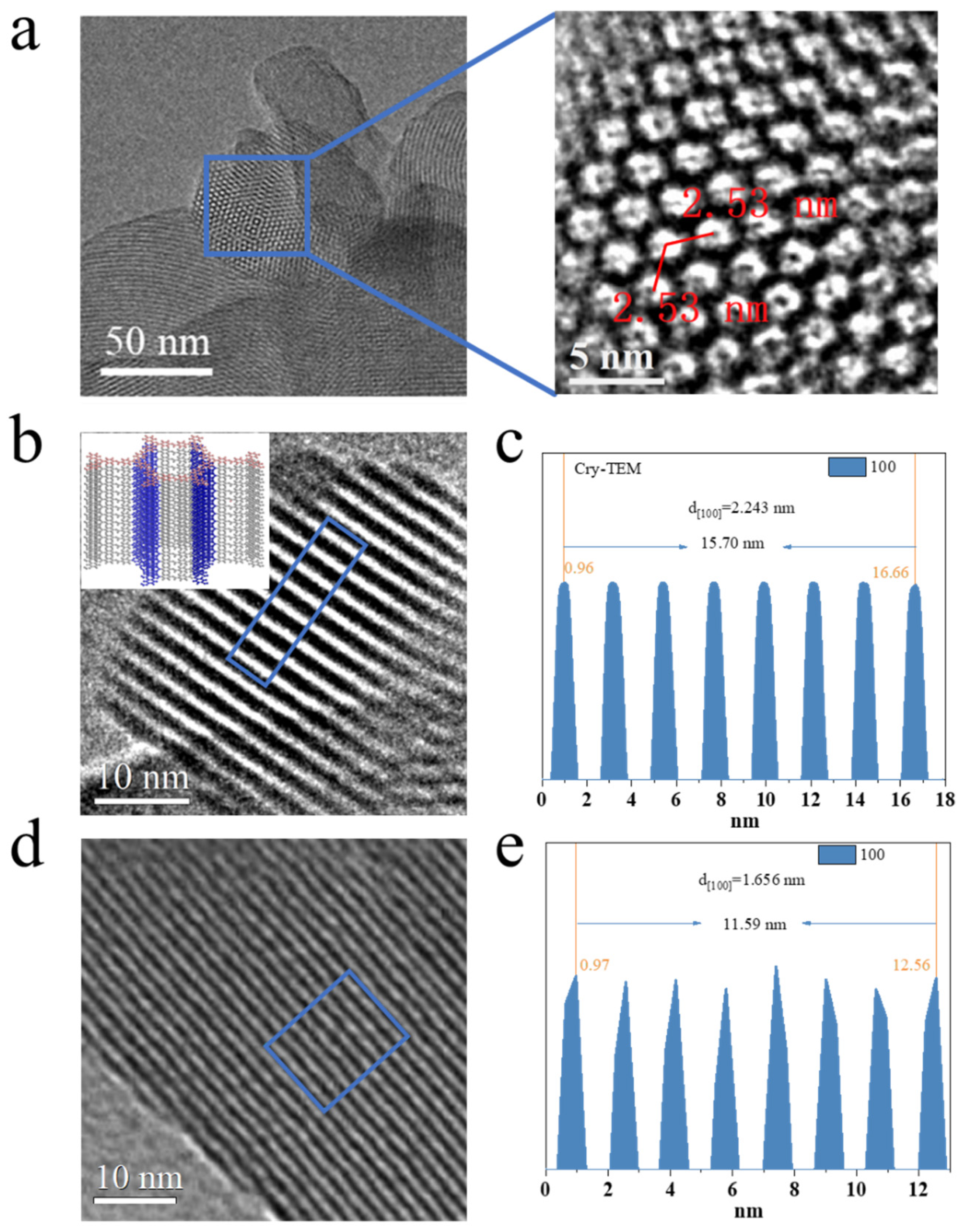
Yaghi, the founder of COF materials, mentioned that porosity and crystallization are two key features of the formation of COF structures when he first reported the COF structure. We have confirmed this feature by PXRD and Ar adsorption-desorption curves. The next step is to directly observe the structure of COF through TEM characterization. Another key to crystal structure confirmation is the direct observation of small crystals through TEM. Theoretically, the ab plane of TAPT-TFPA COF can directly observe the hexagonal pores, and the distance between the pores is the length of one unit cell (25.38 nm). From the ac/bc plane, it can be observed that the distance from the origin to the 100 crystal plane is 2.16 nm, which is just consistent with the pore size. Through the observation of TAPT-TFPT COF crystals at different temperatures, obvious lattice shrinkage behavior was found. As shown in
Figure 4a, a clear and direct hexagonal pore structure can be observed under Cryo-TEM. The distance between the holes is 2.53 nm, which is in good agreement with the theoretical unit cell parameter of 2.538 nm. Due to the small number of atoms at the positions of the side view pores, the relative number of atoms of the edge frame is relatively high. Therefore, the side view of the crystal can directly observe the alternating light and dark lattice fringes, which correspond to the 100 peaks of the unit cell. Under the Cryo-TEM, it can be clearly observed that the 100 peak of the crystal corresponds well to the theoretical value and the experimental PXRD pattern. Surprisingly, the 100 peak of the crystal structure was significantly narrowed to 1.656 nm at room temperature. The high energy of the electron beam has a certain ability to destroy COF. Normally, the electron beam directly causes the lattice fringes to disappear. As we discovered, electron beam-induced lattice shrinkage has never been reported.
3.4. Variable Temperature PXRD
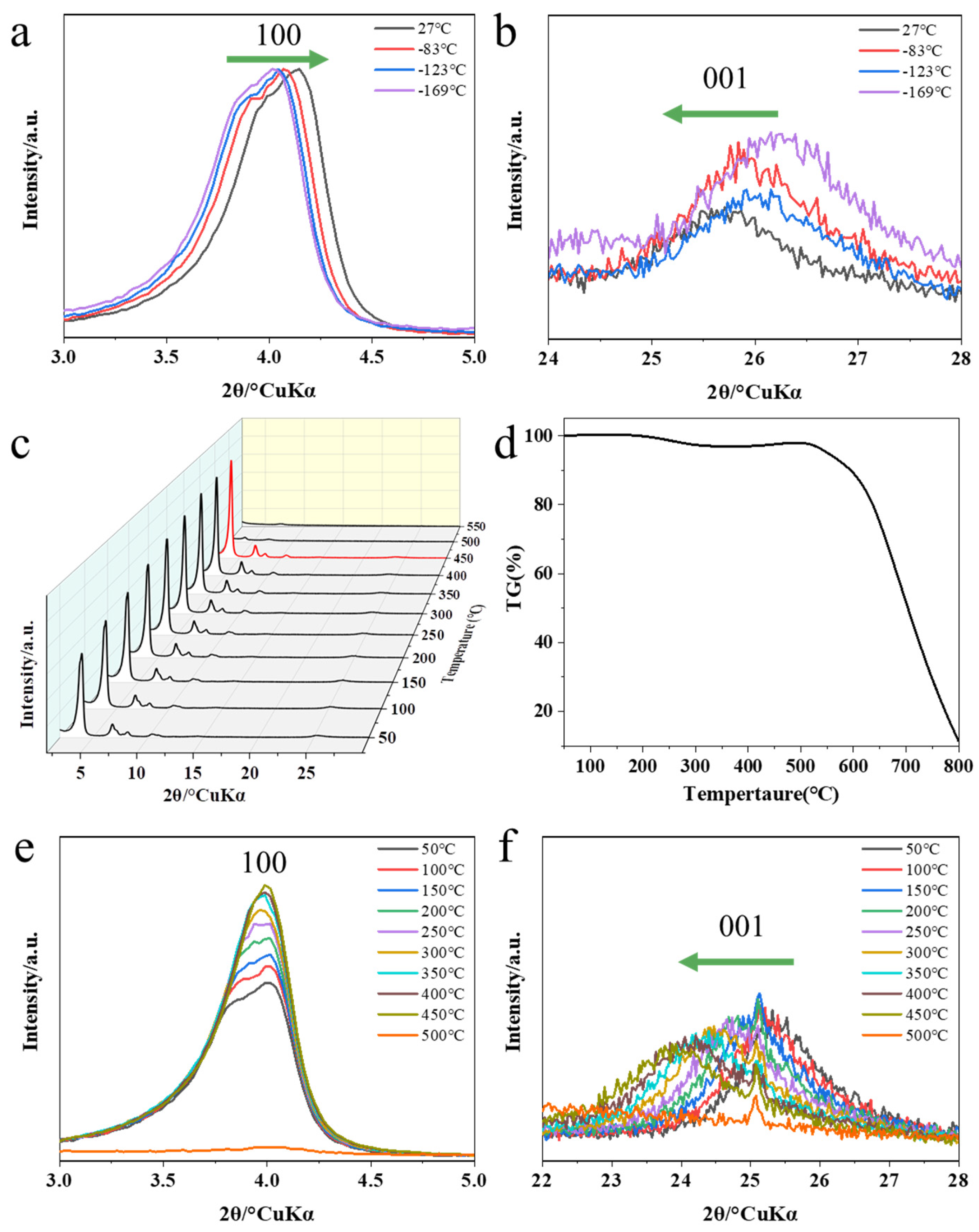
In order to rule out the effect of temperature changes on the crystal structure, we conducted variable temperature PXRD experiments. The results show that as the temperature increases from -196 °C, the molecular motion intensifies, the c axis of the unit cell becomes larger, and the ab axis shrinks. However, due to the limitation of chemical bonds, the range of change is not large. As shown in
Figure 5a,b, as the temperature increases, the 100 peak of the PXRD pattern gradually moves to the right, and the 001 peak gradually moves to the left. Compared with the lattice shrinkage caused by the electron beam, it is even negligible. Therefore, we speculate that the lattice contraction of COFs at different temperatures is due to the quantitative destruction of the lattice structure by the high-energy electron beam rather than the temperature factor.
Since the lattice damage caused by high-energy electron beams can be counteracted at low temperatures, in order to further rule out the lattice shrinkage caused by local high temperatures caused by electron beams, we performed high-temperature PXRD experiments. It can be seen from the thermogravimetric analysis curve that as the temperature increases, TAPT-TFPT COF has a slight quality drop (adsorbed gas impurities) at 200 °C, and then begins to decompose rapidly after reaching 500 °C. In order to further verify the influence of high temperature on the crystal, we conducted in situ high temperature PXRD experiments. As the temperature increases, we can clearly see that the 100 peak gradually increases and reaches its peak when it reaches 500 °C. As the temperature continued to rise, the 100 peak dropped rapidly, and the crystal structure collapsed at this time. There is no obvious unit cell shrinkage behavior in PXRD with increasing temperature. This result indicates that the local high temperature induced by the high-energy electron beam does not lead to the shrinkage of the unit cell. Electron beam radiation is the essential cause of unit cell shrinkage, however, the interaction between electron beam and the electronic structure of COF framework needs further study.
Since the single crystal growth of COF has always been a great challenge in this field, the confirmation of the crystal structure by researchers is limited to PXRD, adsorption curve and TEM electron microscope technology. However, it is not an easy task for the reported COF materials to meet the three technical characterizations at the same time, especially the TEM characterization technology. Because organic compounds are not as resistant to electron radiation as inorganic materials. Although most COF frameworks have clear PXRD pattern, they cannot obtain clear crystal structure information through TEM characterization techniques, which can be attributed to the structural collapse of the COF framework structure under electron beam irradiation. The lattice contraction behavior of TAPT-TFPT COFs reported here under electron beam irradiation is surprising. We confirmed that the structure of the COF was consistent with the theoretical value through the characterization of PXRD and adsorption curves. But a surprising phenomenon of lattice shrinkage was observed in TEM images at different temperatures. We further determined this peculiar electron beam-induced lattice contraction behavior by removing the effect of temperature on the lattice. The lattice contraction behavior induced by the electron beam will provide a typical case of the current electron beam damage mechanism on COF framework materials, and also provide some guidance for more clearly determining the crystal structure through TEM technology. On the other hand, the special interaction between the electron beam and the frame is also expected to open new doors for the study of new physical phenomena.
The customizable long-range ordered structure and block assembly of COF materials make them very suitable as a new class of idealized optoelectronic materials. However, due to various limitations under realistic conditions, its intrinsic conductivity and photoelectric applications have been hindered. Researchers have tried to address the challenges of optoelectronic applications by expanding the conjugation of the monomeric building blocks and connecting bonds, but have been unsuccessful. The essential reason is also due to the imperfection of the COF crystal structure and the uncontrollability of its electronic structure. Therefore, for the field of COF, although TEM characterization technology can be used as a temporary replacement technology to determine its structure, its intrinsic application still urgently needs large-scale defect-free single crystal and two-dimensional single crystal film. Based on this challenge, the research on the electronic structure of COF materials is relatively scarce. In particular, the 2D-COF framework, as a typical two-dimensional material, has the common characteristics of both organic and two-dimensional electronic structures. Effective control of its electronic structure is expected to make it an ideal platform for the study of organic two-dimensional electronics. The lattice contraction caused by the special interaction between the electron beam and the COF framework reported in this paper can not only provide some theoretical guidance for preventing effective electron beam damage characterization techniques, but also serve as an effective entry point into organic two-dimensional electronic study. Extensive and in-depth research on it will provide a certain theoretical basis and guidance for the development of new high-performance optoelectronic materials.
4. Conclusions
In conclusion, in this work, we identify and present for the first time the lattice shrinkage behavior induced by the quantitative destruction of the COF lattice by electron beams. Firstly, we confirmed that the crystal structure of TAPT-TFPT COF is consistent with the theoretical simulation results through PXRD and Ar absorption-desorption curves. Then, by comparing the TEM images at different temperatures, the results show that Cryo-TEM can obtain crystallization information of crystals more accurately and clearly. However, under ordinary room-temperature TEM conditions, the crystal lattice undergoes obvious shrinkage behavior. The damage behavior of the high-energy electron beam to the lattice can be alleviated to a certain extent at low temperature. In order to rule out the effect of temperature changes on the lattice changes, temperature-varying PXRD patterns were collected. The results show that the small changes in the unit cell caused by the temperature change are even negligible, which further confirms that the special interaction between the electron beam and the COF framework structure leads to the occurrence of the lattice behavior. This lattice contraction behavior induced by electron beam irradiation provides a new reference for the confirmation of the crystal structure. On the other hand, electron beam irradiation is expected to develop as a means of producing new materials with molecular-scale differences. Finally, the exotic electronic interactions between electron beams and 2D covalent organic frameworks remain to be further investigated, which lays the foundation for the further development of novel optoelectronic materials.
Author Contributions
Conceptualization, S.S., M.X. and M.S.; methodology, S.L.; software, S.R. and S.L.; validation, S.S., M.X. and S.L.; formal analysis, Y.D.; investigation, S.S. and Y.D.; resources, S.L. and S.R.; data curation, M.X. and Y.D.; writing—original draft preparation, S.R. and M.S.; writing—review and editing, S.S., Y.D. and S.L.; visualization, M.X. and S.R.; supervision, S.S. and M.S.; project administration, M.S.; funding acquisition, S.R. All authors have read and agreed to the published version of the manuscript.
Funding
This research was funded by the China Postdoctoral Science Foundation under Grant No. 2022TQ0399.
Institutional Review Board Statement
Not applicable.
Data Availability Statement
Not applicable.
Acknowledgments
We are grateful that this study was highly supported by the Hengqin government.
Conflicts of Interest
The authors declare no conflict of interest.
References
- Côté, A.P.; Benin, A.I.; Ockwig, N.W.; O’Keeffe, M.; Matzger, A.J.; Yaghi, O.M. Porous, Crystalline, Covalent Organic Frameworks. Science 2005, 310, 1166–1170. [Google Scholar] [CrossRef]
- Lyle, S.J.; Waller, P.J.; Yaghi, O.M. Covalent Organic Frameworks: Organic Chemistry Extended into Two and Three Dimensions. Trends in Chemistry 2019, 1, 172–184. [Google Scholar] [CrossRef]
- Jin, Y.; Hu, Y.; Zhang, W. Tessellated multiporous two-dimensional covalent organic frameworks. Nature Reviews Chemistry 2017, 1, 0056–0067. [Google Scholar] [CrossRef]
- Zhu, L.; Zhang, Y.-B. Crystallization of Covalent Organic Frameworks for Gas Storage Applications. Molecules 2017, 22, 1149–1178. [Google Scholar] [CrossRef] [PubMed]
- Wu, M.-X.; Yang, Y.-W. Applications of covalent organic frameworks (COFs): From gas storage and separation to drug delivery. Chinese Chemical Letters 2017, 28, 1135–1143. [Google Scholar] [CrossRef]
- Jin, F.; Lin, E.; Wang, T.; Geng, S.; Hao, L.; Zhu, Q.; Wang, Z.; Chen, Y.; Cheng, P.; Zhang, Z. Rationally Fabricating Three-Dimensional Covalent Organic Frameworks for Propyne/Propylene Separation. Journal of the American Chemical Society 2022, 144, 23081–23088. [Google Scholar] [CrossRef]
- Jin, F.; Lin, E.; Wang, T.; Geng, S.; Wang, T.; Liu, W.; Xiong, F.; Wang, Z.; Chen, Y.; Cheng, P.; et al. Bottom-Up Synthesis of 8-Connected Three-Dimensional Covalent Organic Frameworks for Highly Efficient Ethylene/Ethane Separation. Journal of the American Chemical Society 2022, 144, 5643–5652. [Google Scholar] [CrossRef]
- Yang, J.; Ghosh, S.; Roeser, J.; Acharjya, A.; Penschke, C.; Tsutsui, Y.; Rabeah, J.; Wang, T.; Djoko Tameu, S.Y.; Ye, M.-Y.; et al. Constitutional isomerism of the linkages in donor–acceptor covalent organic frameworks and its impact on photocatalysis. Nature Communications 2022, 13, 6317–6327. [Google Scholar] [CrossRef]
- He, T.; Zhao, Z.; Liu, R.; Liu, X.; Ni, B.; Wei, Y.; Wu, Y.; Yuan, W.; Peng, H.; Jiang, Z.; et al. Porphyrin-Based Covalent Organic Frameworks Anchoring Au Single Atoms for Photocatalytic Nitrogen Fixation. Journal of the American Chemical Society 2023, 145, 6057–6066. [Google Scholar] [CrossRef]
- Ding, S.-Y.; Gao, J.; Wang, Q.; Zhang, Y.; Song, W.-G.; Su, C.-Y.; Wang, W. Construction of Covalent Organic Framework for Catalysis: Pd/COF-LZU1 in Suzuki–Miyaura Coupling Reaction. Journal of the American Chemical Society 2011, 133, 19816–19822. [Google Scholar] [CrossRef]
- Yusran, Y.; Fang, Q.; Valtchev, V. Electroactive Covalent Organic Frameworks: Design, Synthesis, and Applications. Advanced Materials 2020, 32, 2002038–2002065. [Google Scholar] [CrossRef]
- Shao, M.; Liu, Y.; Guo, Y. Customizable 2D Covalent Organic Frameworks for Optoelectronic Applications. Chinese Journal of Chemistry 2023, 41, 1260–1285. [Google Scholar] [CrossRef]
- Shao, M.; Zhang, Q.; Wei, X.; Chen, J.; Gao, W.; Liu, G.; Kuang, J.; Bian, Y.; Wang, C.; Liu, Y.; et al. Twisted node modulation of 2D-COFs for programmable long-afterglow luminescence. Cell Reports Physical Science 2023, 4, 101273–101285. [Google Scholar] [CrossRef]
- Keller, N.; Bein, T. Optoelectronic processes in covalent organic frameworks. Chemical Society Reviews 2021, 50, 1813–1845. [Google Scholar] [CrossRef]
- Meng, Z.; Stolz, R.M.; Mirica, K.A. Two-Dimensional Chemiresistive Covalent Organic Framework with High Intrinsic Conductivity. Journal of the American Chemical Society 2019, 141, 11929–11937. [Google Scholar] [CrossRef]
- Chen, S.; Yuan, B.; Liu, G.; Zhang, D. Electrochemical Sensors Based on Covalent Organic Frameworks: A Critical Review. Frontiers in Chemistry 2020, 8, 601044–601055. [Google Scholar] [CrossRef]
- Yang, L.; Jin, Y.; Wang, X.; Yu, B.; Chen, R.; Zhang, C.; Zhao, Y.; Yu, Y.; Liu, Y.; Wei, D. Antifouling Field-Effect Transistor Sensing Interface Based on Covalent Organic Frameworks. Advanced Electronic Materials 2020, 6, 1901169–1901176. [Google Scholar] [CrossRef]
- Fang, Q.; Wang, J.; Gu, S.; Kaspar, R.B.; Zhuang, Z.; Zheng, J.; Guo, H.; Qiu, S.; Yan, Y. 3D Porous Crystalline Polyimide Covalent Organic Frameworks for Drug Delivery. Journal of the American Chemical Society 2015, 137, 8352–8355. [Google Scholar] [CrossRef]
- Sun, T.; Lei, W.; Ma, Y.; Zhang, Y.B. Unravelling Crystal Structures of Covalent Organic Frameworks by Electron Diffraction Tomography. Chinese Journal of Chemistry 2020, 38, 1153–1166. [Google Scholar] [CrossRef]
- Du, C.; Na, W.; Shao, M.; Shang, S.; Liu, Y.; Chen, J. Self-Templated Synthesis of Triphenylene-Based Uniform Hollow Spherical Two-Dimensional Covalent Organic Frameworks for Drug Delivery. Chemistry of Materials 2023, 35, 1395–1403. [Google Scholar] [CrossRef]
- Ma, T.; Kapustin, E.A.; Yin, S.X.; Liang, L.; Zhou, Z.; Niu, J.; Li, L.H.; Wang, Y.; Su, J.; Li, J.; et al. Single-crystal x-ray diffraction structures of covalent organic frameworks. Science 2018, 361, 48–52. [Google Scholar] [CrossRef] [PubMed]
- Li, R.L.; Flanders, N.C.; Evans, A.M.; Ji, W.; Castano, I.; Chen, L.X.; Gianneschi, N.C.; Dichtel, W.R. Controlled growth of imine-linked two-dimensional covalent organic framework nanoparticles. Chem Sci 2019, 10, 3796–3801. [Google Scholar] [CrossRef] [PubMed]
- Evans, A.M.; Parent, L.R.; Flanders, N.C.; Bisbey, R.P.; Vitaku, E.; Kirschner, M.S.; Schaller, R.D.; Chen, L.X.; Gianneschi, N.C.; Dichtel, W.R. Seeded growth of single-crystal two-dimensional covalent organic frameworks. Science 2018, 361, 53. [Google Scholar] [CrossRef]
- Xu, H.S.; Luo, Y.; Li, X.; See, P.Z.; Chen, Z.X.; Ma, T.Q.; Liang, L.; Leng, K.; Abdelwahab, I.; Wang, L.; et al. Single crystal of a one-dimensional metallo-covalent organic framework. Nat. Commun. 2020, 11, 6. [Google Scholar] [CrossRef]
- Sun, T.; Hughes, C.E.; Guo, L.S.; Wei, L.; Harris, K.D.M.; Zhang, Y.B.; Ma, Y.H. Direct-Space Structure Determination of Covalent Organic Frameworks from 3D Electron Diffraction Data. Angew. Chem.-Int. Edit. 2020, 59, 22638–22644. [Google Scholar] [CrossRef]
- Sun, T.; Wei, L.; Chen, Y.C.; Ma, Y.H.; Zhang, Y.B. Atomic-Level Characterization of Dynamics of a 3D Covalent Organic Framework by Cryo-Electron Diffraction Tomography. J. Am. Chem. Soc. 2019, 141, 10962–10966. [Google Scholar] [CrossRef]
- Sun, T.; Lei, W.; Ma, Y.H.; Zhang, Y.B. Unravelling Crystal Structures of Covalent Organic Frameworks by Electron Diffraction Tomography. Chin. J. Chem. 2020, 38, 1153–1166. [Google Scholar] [CrossRef]
- Huang, Z.H.; Grape, E.S.; Li, J.; Inge, A.K.; Zou, X.D. 3D electron diffraction as an important technique for structure elucidation of metal-organic frameworks and covalent organic frameworks. Coord. Chem. Rev. 2021, 427, 14. [Google Scholar] [CrossRef]
- Pütz, A.M.; Terban, M.W.; Bette, S.; Haase, F.; Dinnebier, R.E.; Lotsch, B.V. Total scattering reveals the hidden stacking disorder in a 2D covalent organic framework. Chemical Science 2020, 11, 12647–12654. [Google Scholar] [CrossRef]
|
Disclaimer/Publisher’s Note: The statements, opinions and data contained in all publications are solely those of the individual author(s) and contributor(s) and not of MDPI and/or the editor(s). MDPI and/or the editor(s) disclaim responsibility for any injury to people or property resulting from any ideas, methods, instructions or products referred to in the content. |
© 2023 by the authors. Licensee MDPI, Basel, Switzerland. This article is an open access article distributed under the terms and conditions of the Creative Commons Attribution (CC BY) license (http://creativecommons.org/licenses/by/4.0/).
