Preprint
Article

Optimization of Spray Tower Gas Scrubbers for Water-Tube Boilers

Altmetrics

Downloads

166

Views

58

Comments

0

Submitted:

31 August 2023

Posted:

05 September 2023

You are already at the latest version

Alerts
Abstract
The sugar company Valdez S.A. Entity located within the geographical limits of the city of Milagro, needs to reduce its emissions to the environment and does not always comply with the air emissions standards for stationary combustion sources, which indicates that for equipment installed before 2003 they have a maximum limit of 300 mg / m³. A mist eliminator was designed to work inside the original wet gas scrubber of the water-tube cauldron #10, which uses Bagasse as fuel, for the generation of steam for industrial use. The research is documentary and field. The methodology used was mixed. focusing on the comparison of three types of technologies to meet the objectives, the fog eliminators types: Demister, Cyclone and Chevron. To find the appropriate complement, a comparison sheet was made, which is a table of contents evaluated quantitatively, analyzing indicators formulated in each of the contents. The results, supported by the Multiple Criteria Decision Analysis methodology, select the Chevron type fog eliminator, with the best efficiency for capture. Using AutoCAD, allows to visualize in 3D, the structural design in the gas scrubber.
Keywords: 
Subject: Engineering  -   Industrial and Manufacturing Engineering

1. Introduction

The sugar industry has a diversification of products from sugar cane that gives it great productive potential, for example, the generation of steam for the heat transfer in sugar processing processes and cogeneration of electrical energy. The CAVSA, located in the city of Milagro-Ecuador, for its industrial processes produces steam through water-tube cauldrons, called: cauldron # 10, cauldron # 11 and cauldron # 12. Using sugarcane bagasse as fuel. The purpose of the research is to focus attention on cauldron #10, which by the year of manufacture (1980), with a steam production 65000 Kg/h and, working pressure: 21 Kg/cm2 at 275◦C, is the one that presents the greatest problem of emissions of polluting particles to the environment. "The Ecuadorian law through the Standard of air emissions from stationary combustion sources, is issued under the protection of the Environmental Management Law and the Regulation to the Environmental Management Law for the Prevention and Control of Environmental Pollution, mentions that the amount of particulate matter for equipment installed before 2003 has a maximum limit of 300 mg/m3" [1]. At present, the cauldron # 10 partially complies with the parameters issued in the environmental law, since the conditions of continuity do not maintain them during the harvest periods, due to this problem caused at that time, the present work is developed. The research project aims to: diagnose the current particulate matter collection of the cauldron gas scrubber and design additional equipment that improves its efficiency, so that the amount of particulate matter emitted into the atmosphere is reduced and the level of risk decreases, both for the health of people and the environment. The original technological design principle of the gas scrubber, consists of a spray tower, with washing water by injection through nozzles, is justified based on the operation of the cauldron and the amount of gas flow that handles 260000 m3 / h, and ash emissions by the burning of bagasse in the boilers greater than 800 Kg/h, Its design consists of a rectangular prismatic container, in which the gases product of combustion, contain ash and unburned particles, which enter through the upper part of the gas scrubber against flow with the water cone driven by the sprinklers, in such a way that by inertial impact the particles are captured.
Particulate matter makes contact with the tiny droplets of liquid in wet cleaning towers through various mechanisms. Due to their mass, particles with diameters greater than 10 microns are usually collected by impact. However, particles that pass close enough to a drop of water are captured by interception; Capture due to the surface tension of the drop. Particles approximately 1.0 to 0.1 microns in diameter are subject to interception. Increasing the density of droplets in the spray [2].

2. Materials and Methods

2.1. Spray Towers

They are models of cleaning towers of simple operation, which generate less operating costs. The operation of the spray tower consists of the entry of air loaded with particulate matter into the chamber, where it makes contact with the atomized water droplets produced by the nozzles at a temperature higher than the ambient one. There are models that can work with waste gas flow, with either horizontal or vertical trajectory [3].
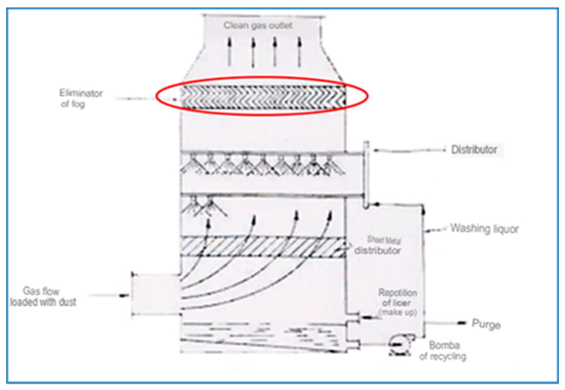
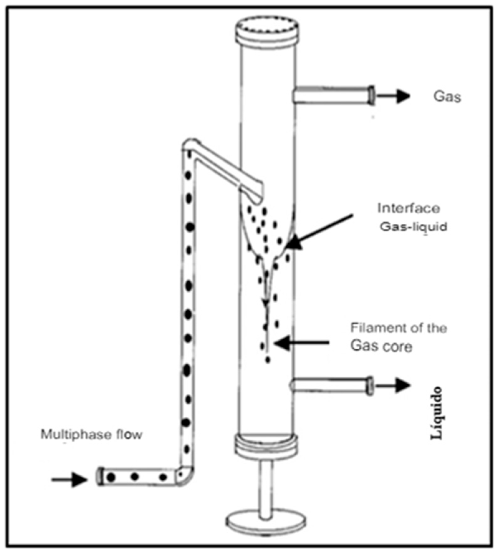
The spraying of the liquid can be countercurrent to the flow of the gas see Figure 1. in the same direction as the gas flow, or perpendicular to the gas flow. The particles are captured by small droplets generated by the nozzles, they are related to principles such as: impact, interception and diffusion. Drops with sufficiently particulate matter large fall by gravity and are collected at the bottom of the tower and then evacuated. But there is a phenomenon called droplet entrainment, they are those that are trapped in the waste gas flow, which must be collected through a dew, mist or droplet eliminator upstream of the nozzles.

2.2. Gas scrubber

"It is a cleaning mechanism known in English as scrubbing, it consists of the passage of a gas containing particles inside a chamber, at which time it makes direct contact with a liquid, which is usually water, in this way the particles are intercepted by the drops of water" [4].
There are different classification criteria for particle scrubbers, they fundamentally consider the energy that the device uses to move the water in its process.

2.3. Particle-separated equipment

Particle separators are devices that control the particles emitted into the air in order to prevent them from generating considerable damage, primarily when handling toxic compounds.
"The main objective of this equipment is the collection of particles emitted at an industrial level before being eliminated into the environment. They can be of several types according to the separation system used, the physical properties of the particles is a fundamental aspect to select the right device. The most used are gravitational sedimentation chambers and cyclonics" [5].

2.4. Mist eliminators

It is estimated that mist or droplet eliminators remove between 90% and 99% of liquid droplets trapped or carried away by the gas stream. The basic models that have the highest frequency of use are the Chevron type fog eliminators and the Mesh Packaging type. The principle of the two types of eliminators is the same, the droplets are collected and coalescing both in the blades of the Chevron or in the filaments of the mesh, where the sufficiently large droplets will fall by gravity or capillarity. Chevron design fog eliminators are most commonly used when handling high loads of particulate matter because mesh packing eliminators can become clogged. It is generally estimated that a mist eliminator whatever the model can generate a pressure drop in the range of 12.7 to 25.4 mm of water column [2].
The mesh packing mist eliminators, is in general the most sensitive, it is a simple metal blanket or plastic mesh that retains the drops of liquid dragged by a gas, it passes through the eliminator the drops impact on an extensive surface of the wire or filament, retaining the drops until they coalesce to increase their size, When the droplets are large enough they fall by gravity against the flow of gases. Demisters are widely used in operations where gases and liquids are involved such as: distillation, absorption, evaporation, it is estimated that they have a low cost, low pressure drop and a high efficiency of liquid collection [6].
The content of liquids in a gas could damage or severely affect the equipment where they circulate, it is necessary to remove the small amounts of liquid droplets found in a gas stream. Mist eliminators are devices that can effectively remove liquid dragged by gas flow, fog removing blades work by the principle of inertial impact. The zigzag shape of the blades causes the gases to be conducted in a zigzag manner, the droplets that cannot follow these changes of direction due to high inertia compared to the gases, impact and remain adhered to the solid surface of the fog eliminator. In vertical flow mist eliminators the collected liquid is drained in countercurrent, this drainage works under the effect of gravity, at the moment that the accumulated amount is on the high surface, forming a film of liquid [7].
Generally, Chevron type mist eliminators are less efficient in capturing smaller droplets compared to other types of inertial impact separators such as Mesh Fabric, but depending on the design parameters on which the Chevron fog eliminator is based, the expected pressure drop will be low and will collect 100% of all droplets in the size range between 10-40 microns of Diameter, this type of mist eliminator is preferable in applications where high gas velocity is involved and low pressure drop is required [8].

2.5. Justification of the fog eliminator model

Based on the characteristics of the gas scrubber, it was determined that ash capture should be improved with devices that are not expensive to manufacture, easy to install and maintain see Figure 2.
In mentions [8] that fog eliminators are widely used in the chemical, oil and gas industry, to capture liquid droplets from the flow of a gas or vapor, another reason for the use of fog eliminators is to restrict emissions of pollutants to the environment, prevent corrosion damage of equipment.
In the sugar industry, mist eliminators are used for the recovery of droplets carried by water vapor containing sugar crystals in a significant proportion. Mist eliminators have a wide range of uses in industries, one of the most common examples of use is the reduction of the amount of make-up water in cooling towers by capturing the smallest water droplets [9].
The main focus of this work is the recovery of water droplets that are carried by the flue gases of boiler # 10, in order to collect a greater amount of ash. The fuel used in water-tube boilers is sugarcane bagasse, which, being a solid fuel, generates ash as a product of combustion, which must be collected to treat it efficiently.
The ash is captured through a spray tower type gas scrubber which uses nozzles with a spherical model, whose sheet thickness is 3 mm, the nozzle is connected to a distribution pipe of Ø 63.5 mm and have an inlet of Ø 19.05 mm, the water used for spraying has an approximate temperature of 40º C in order to lower the temperature of the gases.
The gases enter the scrubber with a pressure of -101.6 mm H₂O at 200ºC and leave with an approximate pressure of -152.4 mm H₂O at a temperature of approximately 100ºC. Blade spacing is a crucial variable for maintaining high separation efficiency and stable scrubber conditions. On the one hand, having a very small blade spacing generates a high pressure drop and a suction system of higher energy consumption would be needed, on the other hand, having a very large spacing would decrease the efficiency of separation of liquid droplets due to their greater area of movement. On the other hand, it mentions that speeds considered high (greater than 6 m / s) are directed to high inertial forces and, at the same time, cause a rapid change of direction of the droplets, forcing them to hit with greater intensity the walls of the blades of the fog eliminator, which results in greater separation efficiency. A high speed causes a breakage of the liquid film which causes dragging and therefore lower separation efficiency [7].
Given [7] it mentions that if this angle between steps of the blades is relatively small it generates a greater centrifugal force of the drops towards the bending of the blades, which causes greater separation efficiency, while the greater the angle of the blades, the efficiency will tend to be lower, in the simulation carried out [7] in case the value of the angle is less than optimal, This will reflect a decrease in separation efficiency.
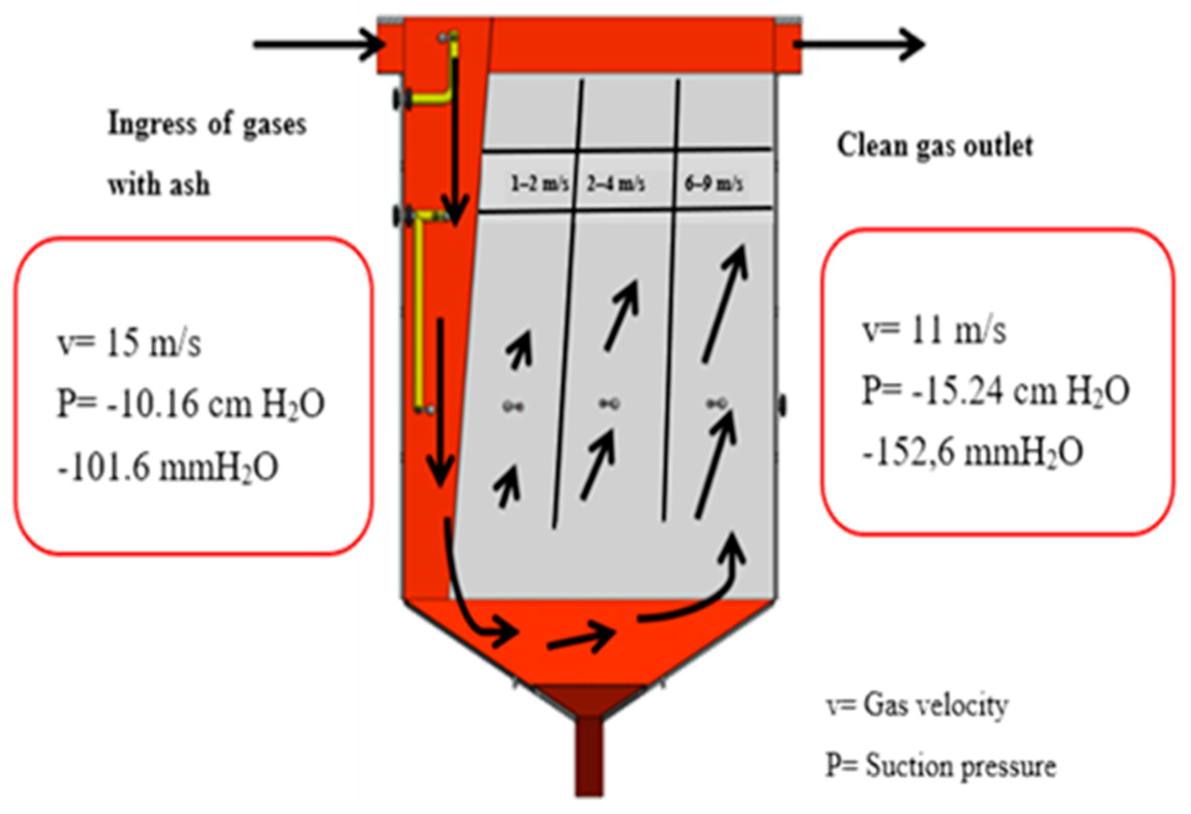
The velocity of the gases to the scrubber is approximately 15 m / s and, an approximate exit speed of 11 m / s, due to the dimensions of the scrubber, the internal speed is approximately 3 m / s which is not a uniform speed due to the behavior of the gases, the scrubber has within its structure baffles that have the function of directing the gases, which do not guarantee the uniformity of the distribution, causing most of the volume to be directed to the last section, see Figure 3.
The installation of a mist eliminator before the exit of the gases was considered, the fog eliminator to be installed is a Chevron type fog eliminator consisting of blades with a defined profile which is studied and analyzed in later sections, and that adapts to the requirements of the gas scrubbing system. The requirements of the gas scrubbing system are:
"The handling of particles in a proportion of 5% of the amount of particles (ash) emitted by the combustion of bagasse, it should be noted that cauldron # 10 does not work at 100% design production for steam generation and does so in smaller capacities, there is no certain value of the amount of ash generated by combustion, there is a referential data of the amount of ash with the cauldron at 100%. The study carried out in November 1996 by the company Environmental Analysis of Cali - Colombia, mentions the following results obtained"[4].
Particulate emission: 891.29 Kg/hour
Gas flow chimney conditions: 265398.5 m³/hour
Gas temperature: 202.67 ºC
The emission of particles in 5% is around 44.56 kg / hour, considering 100% steam generation, values that, when multiplied by the harvest hours, have approximately 192500 Kg emitted to the environment.

2.6. Methodology

The methodology used to reduce the emission of ash and unburned particles has a mixed research approach [10]. From the quantitative point of view each stage precedes the next, starting from the idea of pollution by the emission is ash and, which aims to improve the collection of this material, has also reviewed the literature regarding gas scrubbers and fog eliminators specifying the theoretical framework with respect to them.
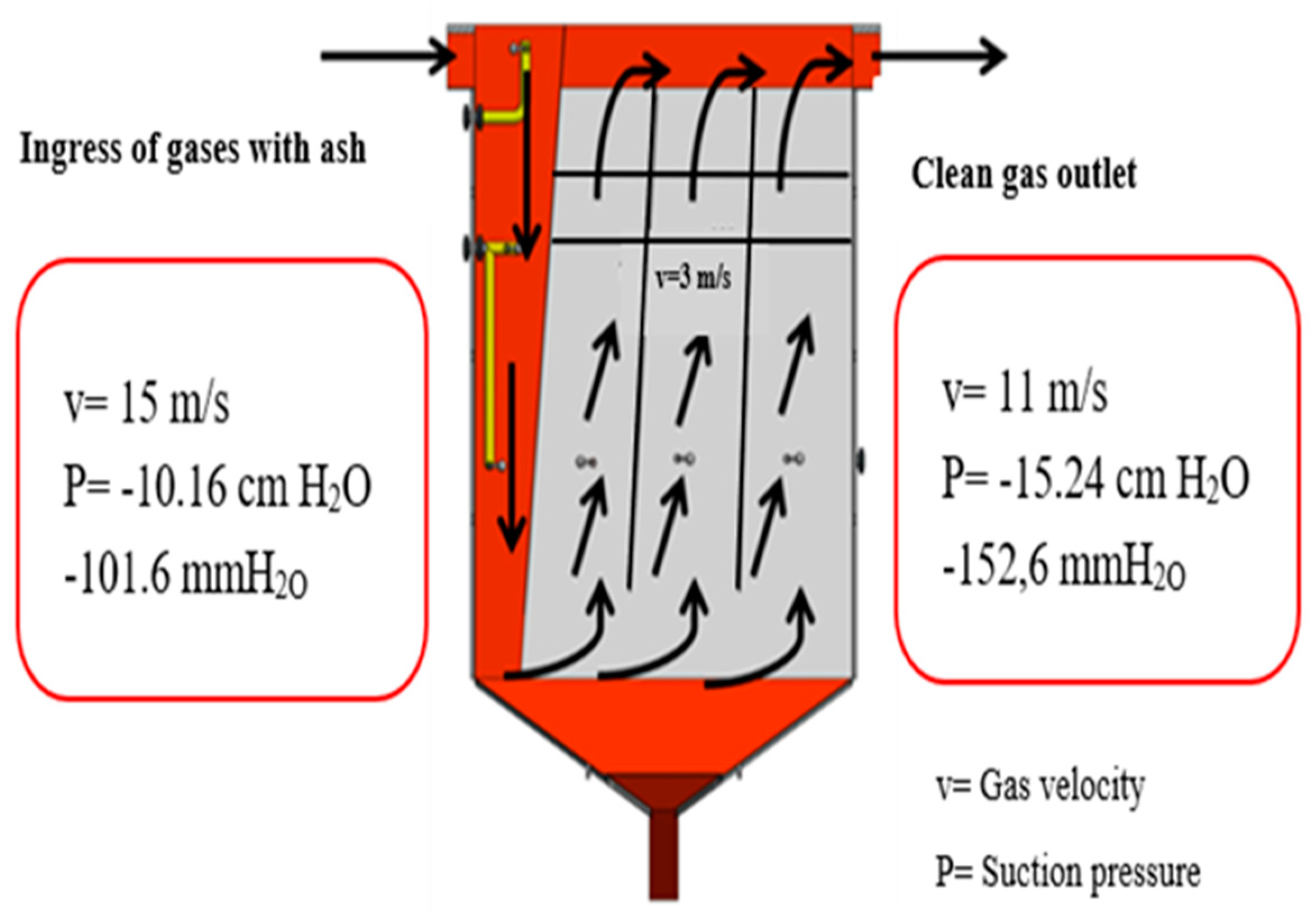
Based on the hypothesis that the gas scrubber does not work correctly throughout the harvest, the variables have been considered as volumetric flow of gases, volumetric flow of water entering for gas scrubbing, mass flow of ash-unburned, both at the inlet and outlet, see Figure 4 and, As shown in later sections, making various measurements with respect to the ash catchment system. The qualitative part of the research, correspond to the data on ash emissions before installing the gas scrubber in November 1996, which indicate the amount of gases and ash that were emitted with the boiler # 10 working at 100%, it is estimated that the gas scrubber currently does not work efficiently throughout the harvest, the research work seeks to find the solution of this inefficient operation.
Due to the present mixed methodology research, data are collected, analyzed and inferences are formulated using quantitative and qualitative methods [11].

2.6.1. Material and procedure

The objective of this optimization process is to improve the performance of spray tower gas scrubbers for water-tube boilers. To achieve this goal, several steps will be taken. First, a visual inspection of the boiler will be performed to identify potential problems. This will include checking water levels, boiler pressure, fuel level, water temperature, airflow and outlet pressure. Once the issues have been identified, the necessary adjustments will be made to improve performance.

2.6.2. Methods and techniques

The method that will be used is the explanatory one, because it will allow the causes and effects of the investigation to be cleared, based on the design of an additional team that works with the gas scrubber of the water-tube boiler # 10, this will help the fulfillment of the objectives set.

2.7. Multiple Criteria Decision Analysis Method (MCDAM)

For the selection of the ideal proposal that favors the reduction of the emission of particulate matter and gases, it uses the method of decision analysis with multiple criteria (MCDAM). The method evaluates different criteria with different scales, which help decision-making according to the needs of the institution, in the case of CAVSA and choose the alternative that works with the gas scrubber of the water-tube boiler #10.

2.8. Matching card technique

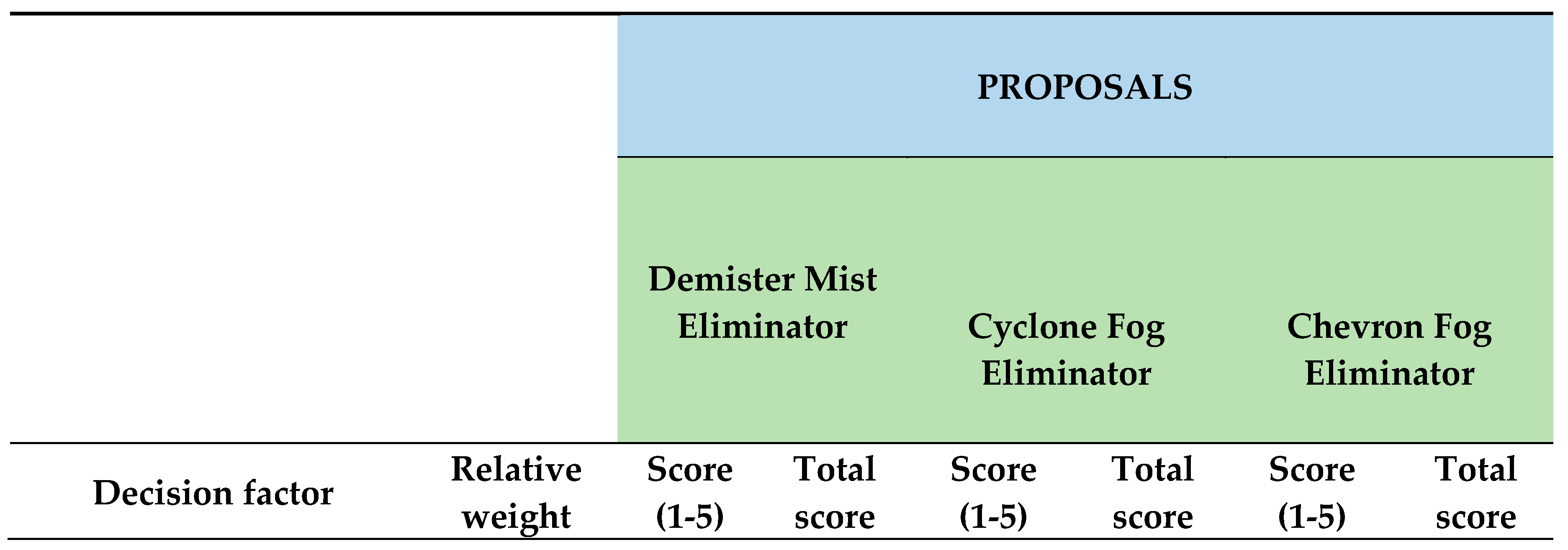
There are several alternatives to work with the gas scrubber and meet the objectives set, which are commonly used are: Demister fog eliminator, Cyclone fog eliminator and, Chevron type fog eliminator; In order to find the appropriate complement, a comparison sheet will be made, which consists of a table of contents evaluated quantitatively, which serve to analyze if the indicators formulated for each of the contents, are adapted to the research developed and allow obtaining adequate results taking into account the following: time, place and, the needs of the project.
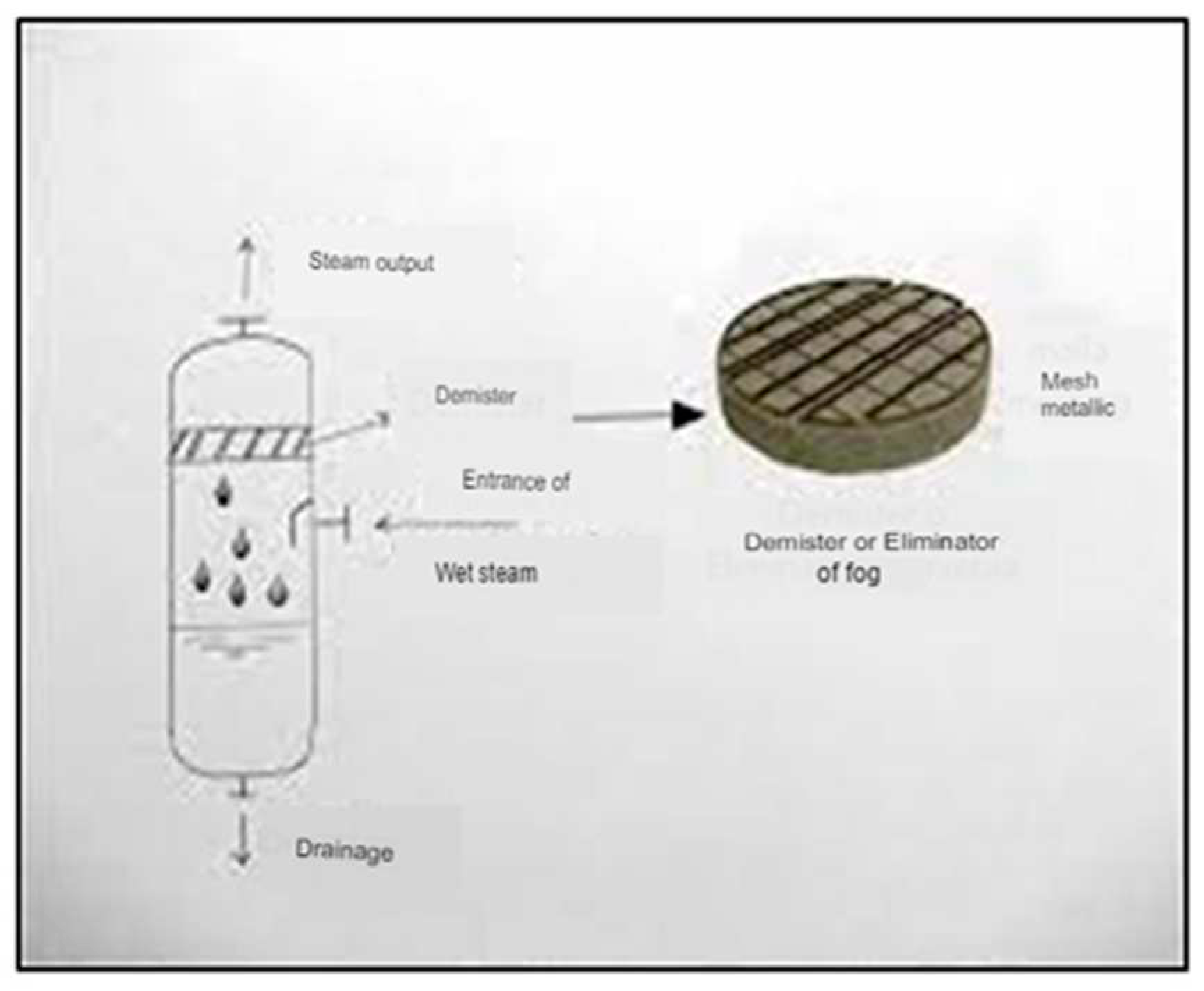
Demister mist eliminators are used to separate liquid droplets from a flowing medium in the form of gas and are used in gas filtration. For this, the Demister serves as a pre-separator when the gas contains many impurities. On the other hand, the solid substances contained in the liquid can only be removed up to a certain point. That is why it is mainly used in switchable filters. Demisters, see Figure 5, are resistant to changes in operating conditions such as pressure or flow.
Cyclone type separators, use centrifugal force to separate components of different phases and densities, the force acting on liquid droplets is five times greater than gravity in large equipment, at low speeds and up to 2000 times in small equipment at high pressure. The cyclone separator is recognized and accepted in a variety of applications, from steam condensate to furnace powders [13]; [14]; [15].
In this equipment, the carrier gas and suspended droplets enter tangentially into a cylindrical or conical section of the separator, as shown in Figure 6. The mixture then spirals downward, forcing the heavier suspended matter against the walls. The condensate droplets moisten the wall, forming a descending film, which is removed from the bottom [16].
The control efficiency range for conventional cyclones is estimated to be between 70 and 90% for particles with diameters greater than 20μm, between 30 and 90% for particles with diameters greater than 10μm and 0 to 40% for particles with diameters from 2.5 μm. Spray eliminators remove between 90% and 99% of liquid droplets from the waste gas stream. There are two basic designs, Chevron dew eliminators and mesh packaging removers. The droplets are collected and coalesced into the Chevron blades or mesh. When the droplets are large enough, they fall by gravity or capillarity.
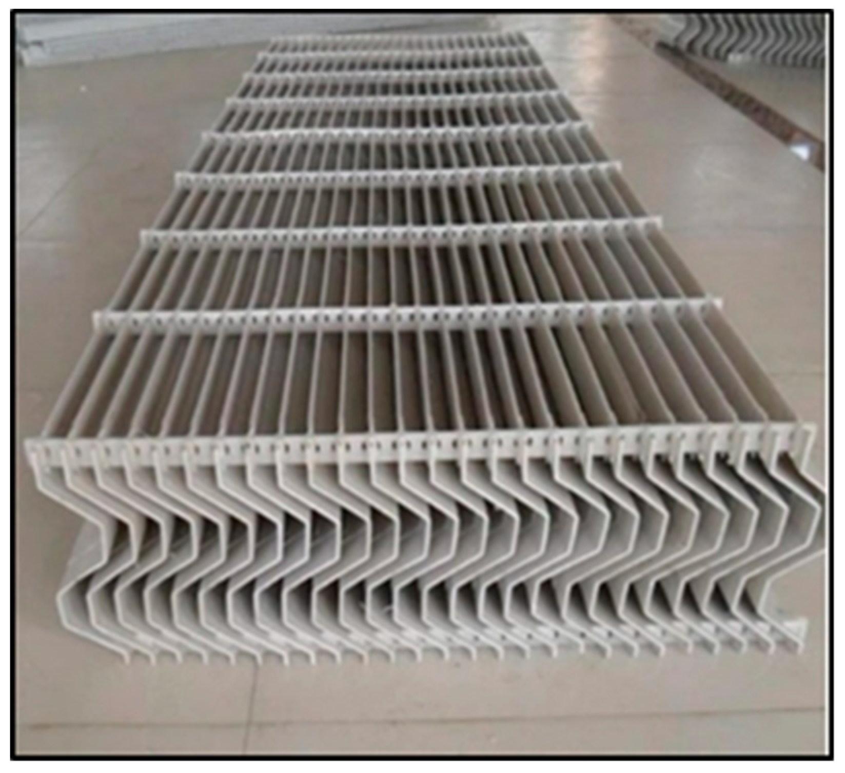
Mesh packing spray eliminators can be clogged with particulate matter; therefore, Chevron designs are applied more frequently. The pressure drop through the dew eliminator is low, from 1.27 to 2.54 centimeters of water (centimeter of water column-in w.c.). Note Figure 7
All dew eliminators require periodic washes to remove accumulated PM” (Yuanfeng. Retrieved January 6, 2023, from http://es.yfenvironment.com/mist-eliminator/chevron-vane-type-mist-eliminator.html).

3. Results

3.1. Fog Eliminator Design

For the design, several aspects were taken into account, referring to the working conditions such as: operation of the gas scrubber, the flow of gases entering and leaving, reference data of the collection efficiencies, profile determined according to the fog eliminator model, ease of cleaning and maintenance.
The project aimed to be a pilot, to continuously capture more ash and, for this, a fog eliminator system was designed, which is detailed in this part of the investigation: location, dimensions and technical specifications of the built element.

3.2. Characterization of gas scrubbing nozzles

During the characterization of the nozzles, we worked with one of the two centrifugal gas scrubbing pumps of 1.67 m³/min, driven by an electric motor of 29828 Watts and nominal pressure of 482633 Pa. Therefore, the original installation was used increasing the diameter of the pipe and fittings to Ø25.4mm" with a diameter reducer from Ø12.7mm to Ø25.4mm, a valve and pressure gauge was installed before the exit of the test sprinkler to observe the outlet pressure and define the cone pattern, see Table 1.
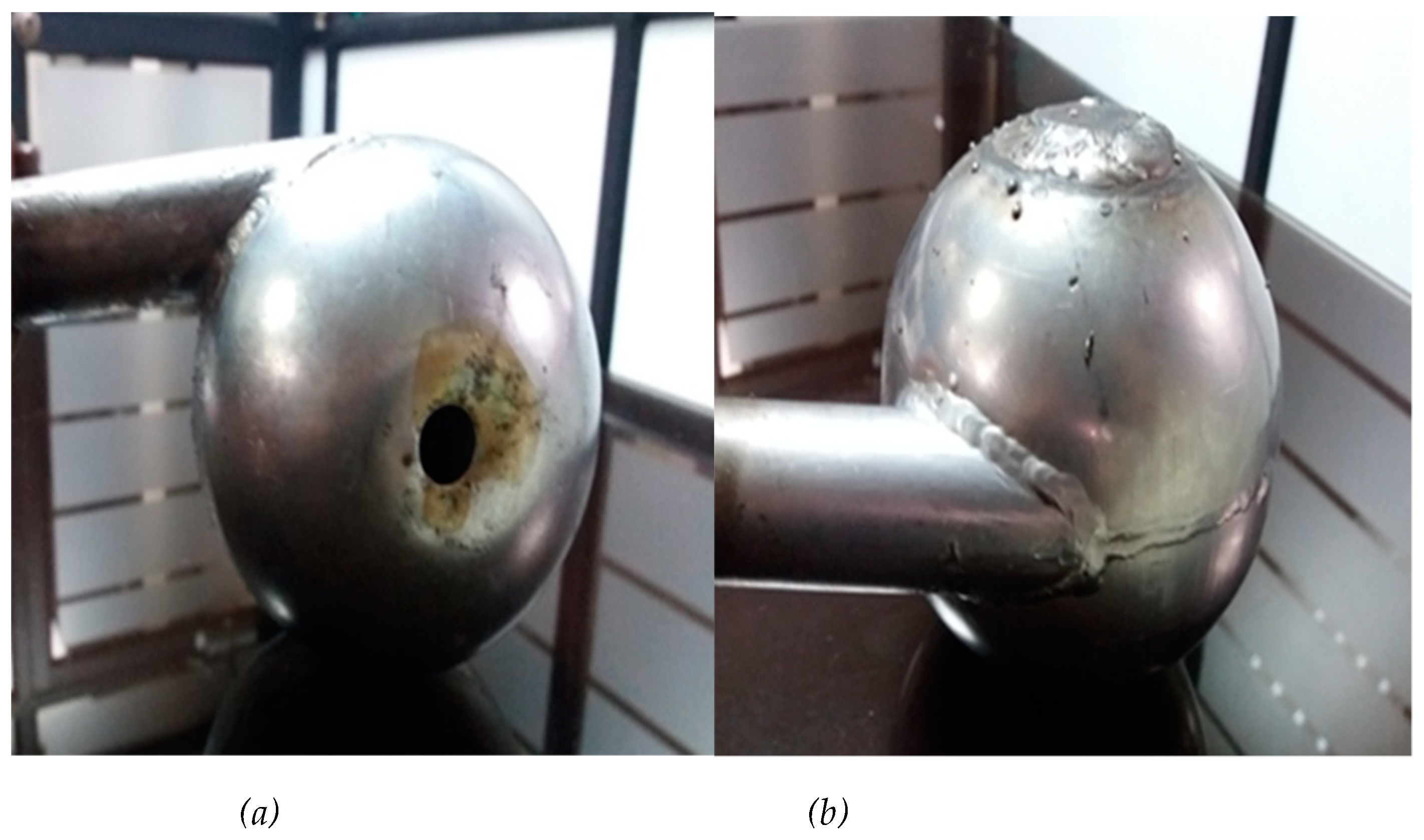
The physical characteristics of the washing nozzles are: nominal diameter of the sphere is Ø100 mm with a thickness of 3 mm, it also has a nozzle diameter of Ø 14 mm, the water inlet pipe is Ø 19.05 mm with ID 80, on one side to generate a tangential cone-shaped flow, as shown in the graphs in Figure 8.
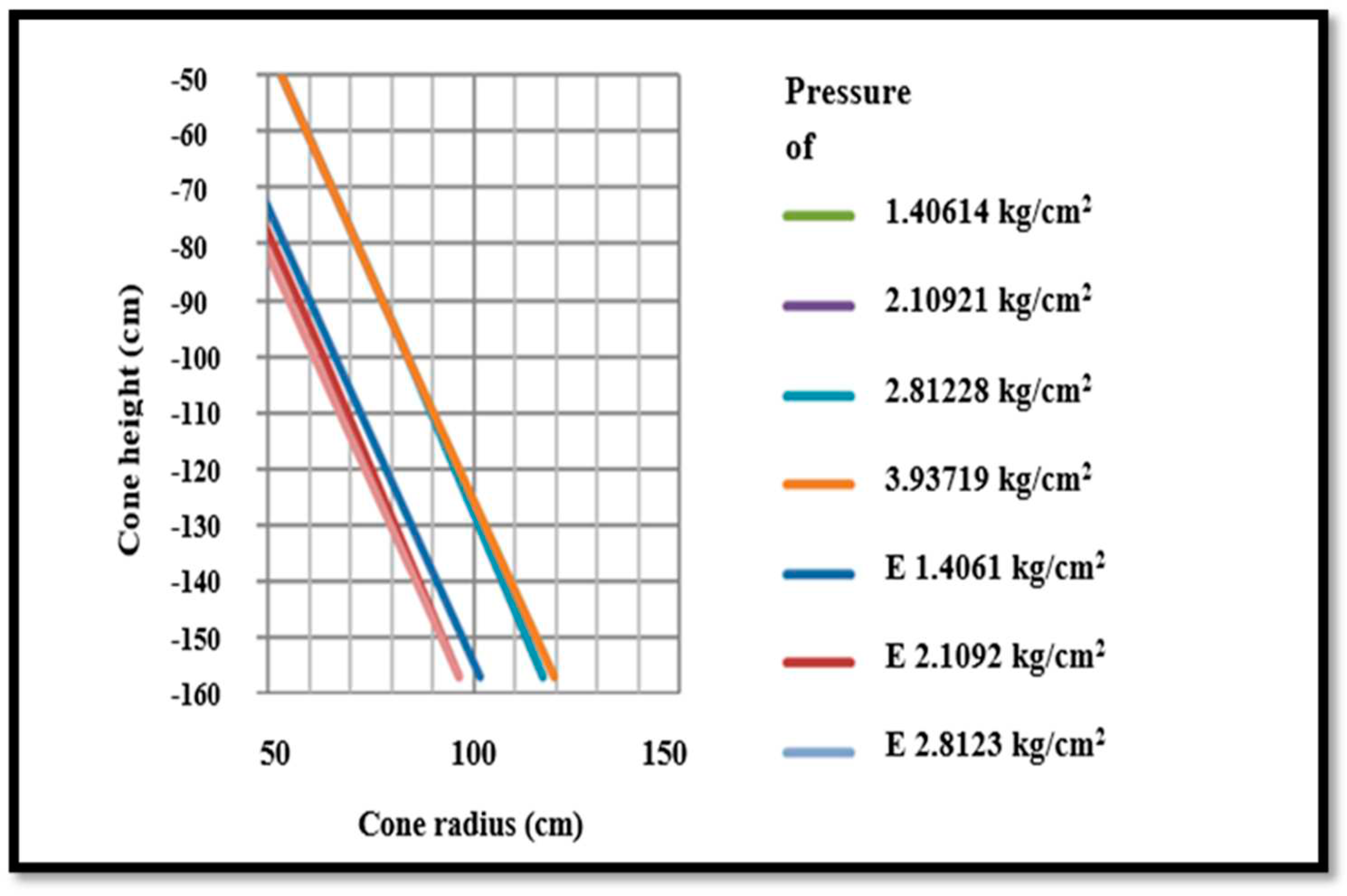
In Figure 9, the characterization of the washing showers can be evidenced, which lead to the formation of the cone with the test nozzle, described in graph 9, where it is observed how the shape of the cone varies significantly at different pressures.
The data presented are taken from a height -50 cm, taking as a reference system the zero in the shower nozzle.
There is a considerable difference between the velocity of gases and the velocity of water droplets.
The size of the droplets is directly related to the outlet pressure, the higher the pressure, the smaller the droplet size, therefore the appropriate working pressure had to be found to maintain the relative velocity at high values.
The proper pressure for the formation of the cone in the nozzle is between 206843 and 275790 Pa.
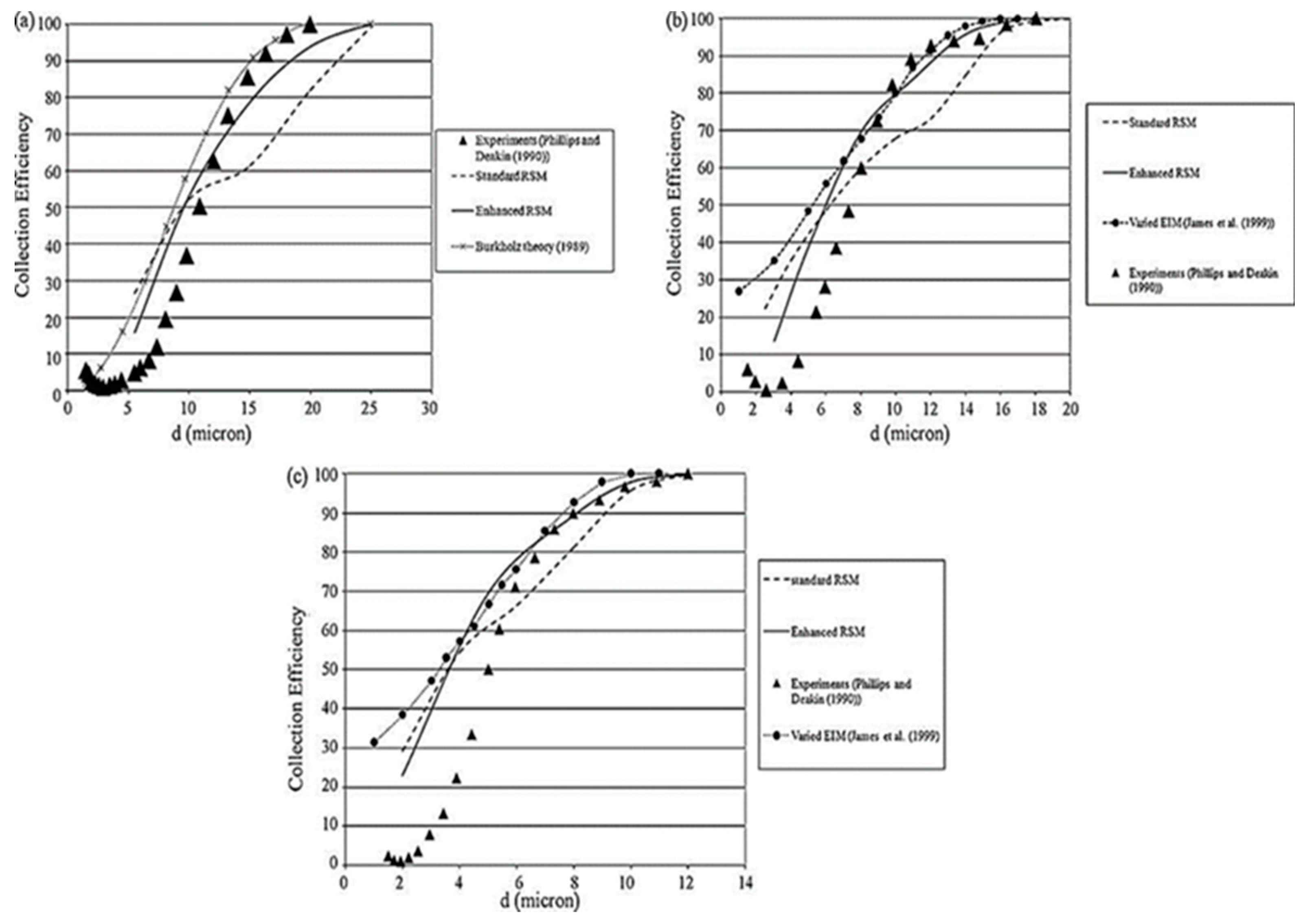
Figure 10 shows the results of the experiments, tested at different gas velocities, 1m/s, 2m/s and 5 m/s. The figures show us 2 considerations: the first that the larger the droplet size the collection efficiency increases significantly since all are increasing, taking as a reference point the diameter of 18 microns of the drop, we observe that, in the 3 figures, the collection efficiency exceeds 90%.
The second consideration is with respect to the velocity of the gases, according to Figure 10 at a higher speed the collection efficiency, this increases in number of smaller droplets, this is because at a higher speed there is a greater impact force towards the smaller droplets. For example, if we take as a reference point in the three figures, the droplet diameter of 10 microns it is observed that the collection efficiency increases, the efficiency of 54% in the graph "a", 79% for the graph "b" and 97% for the graph "c".
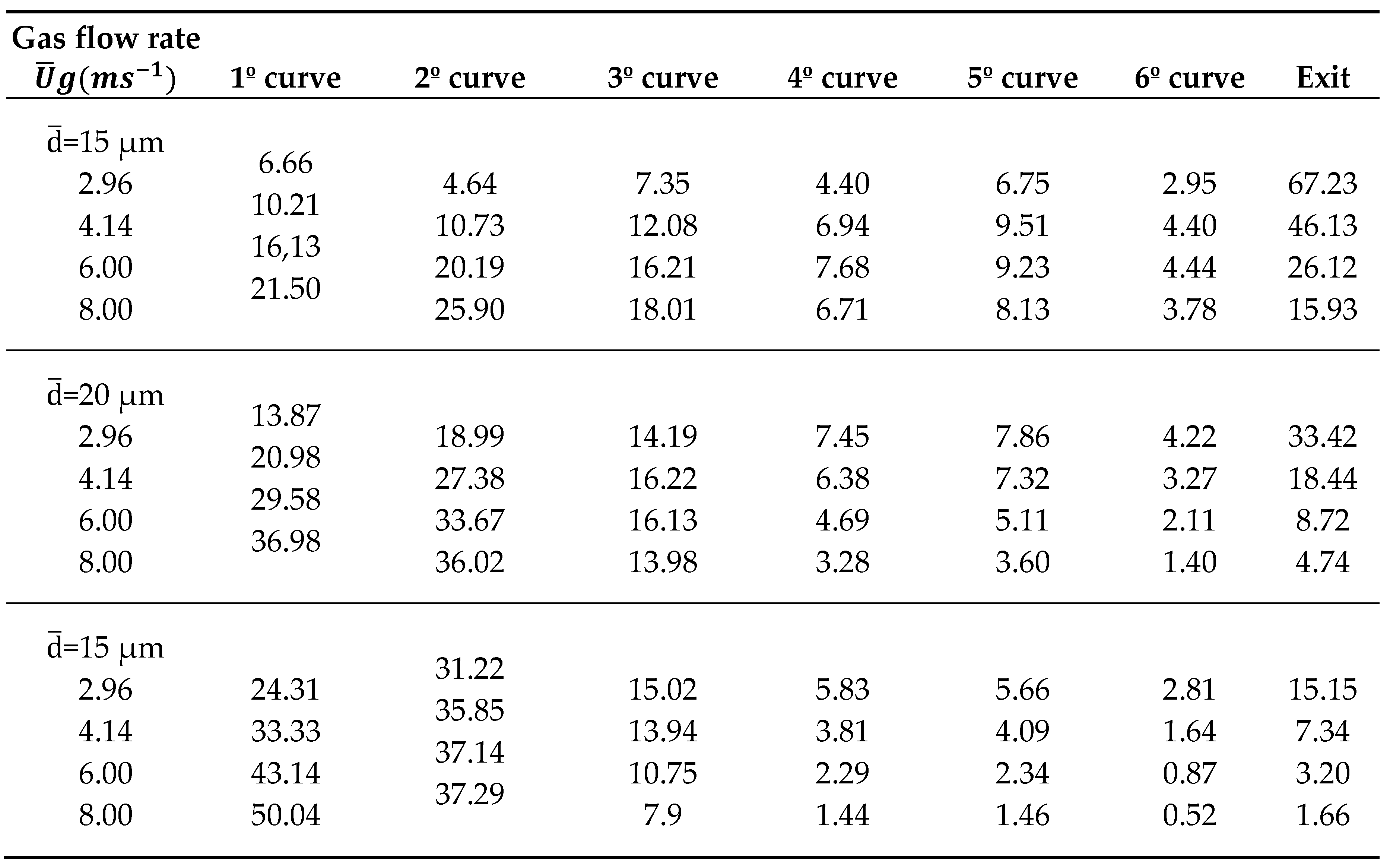
Table 2 describes the results of the [19], which supports results based on [9] with respect to the collection efficiency, which, the larger the droplet size, the greater the speed, but with the addition of the number of curves. They show us that the highest percentage of collection is found in curves 1° and 2°, being the first where a significant percentage is collected at high speeds.
The profile adopted for the pilot project is based on the patent design of (United States Patent No. 6,083,302, 2000) within which the authors conducted tests to determine the collection efficiency it has.
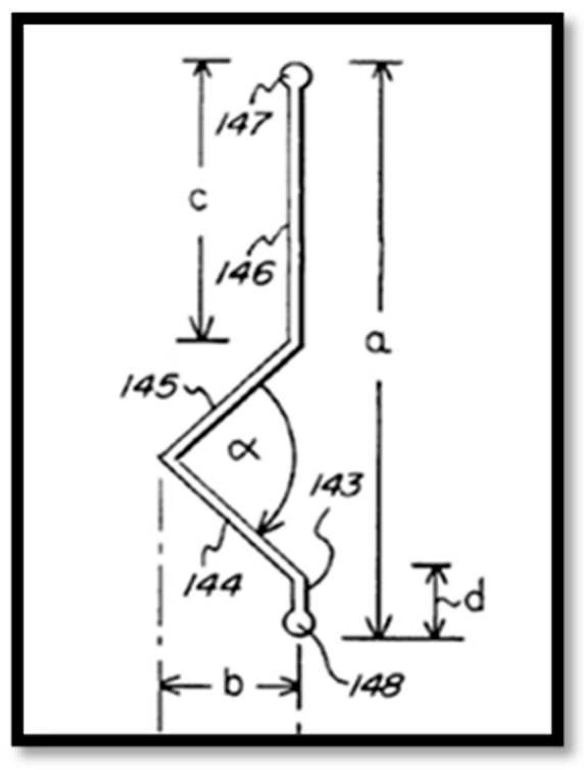
The objective of the mist eliminator is to collect the drops of water that have or do not have ash particles that are dragged by the combustion gases, based on the requirements a design of two passes of a single stage was used, which has an extension to the exit for better capture and greater ease of cleaning, according to [20] the design criteria are as follows:
Figure 11 shows the profile of the fog eliminator of a stage and two passes, the passes are those defined by the alpha angle, and a profile width denoted by the letter "b", and an exit extension expressed by the letter "c".
See Table 3, all dimensions are related, so the designed profile has the following dimensions:
Dimensions of the profile of the fog eliminator, whose yields are:
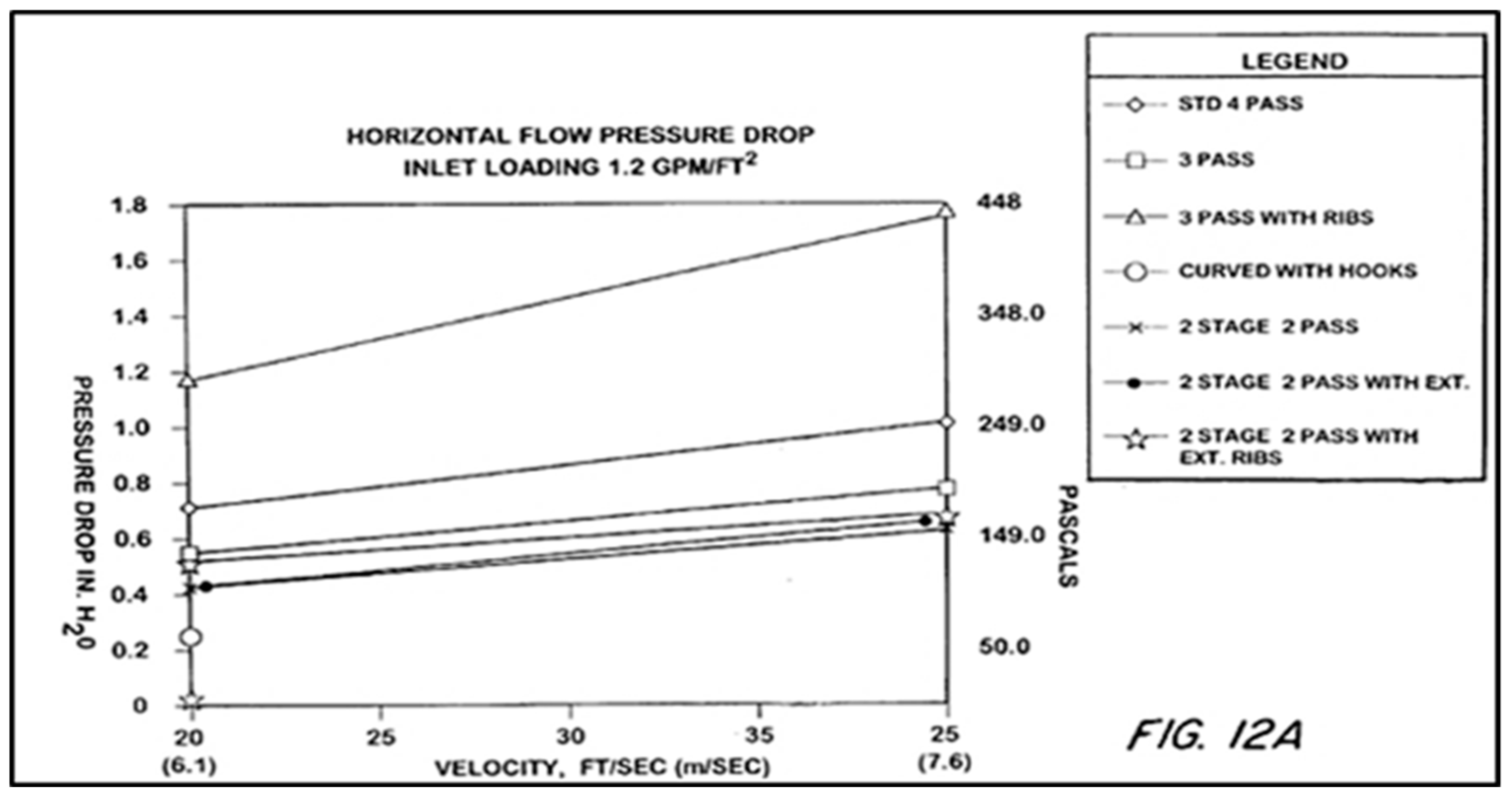
Figure 12 shows the behavior of 6 fog eliminator configurations on a test bench to determine the pressure drop, in Figure 9 the droplet collection efficiency was determined, the two tests were for horizontal airflow.
The 6 configurations were not detailed, we only focused on the two-stage configuration with two steps with extension, described in Figure 12 as: "2 stage 2 pass".
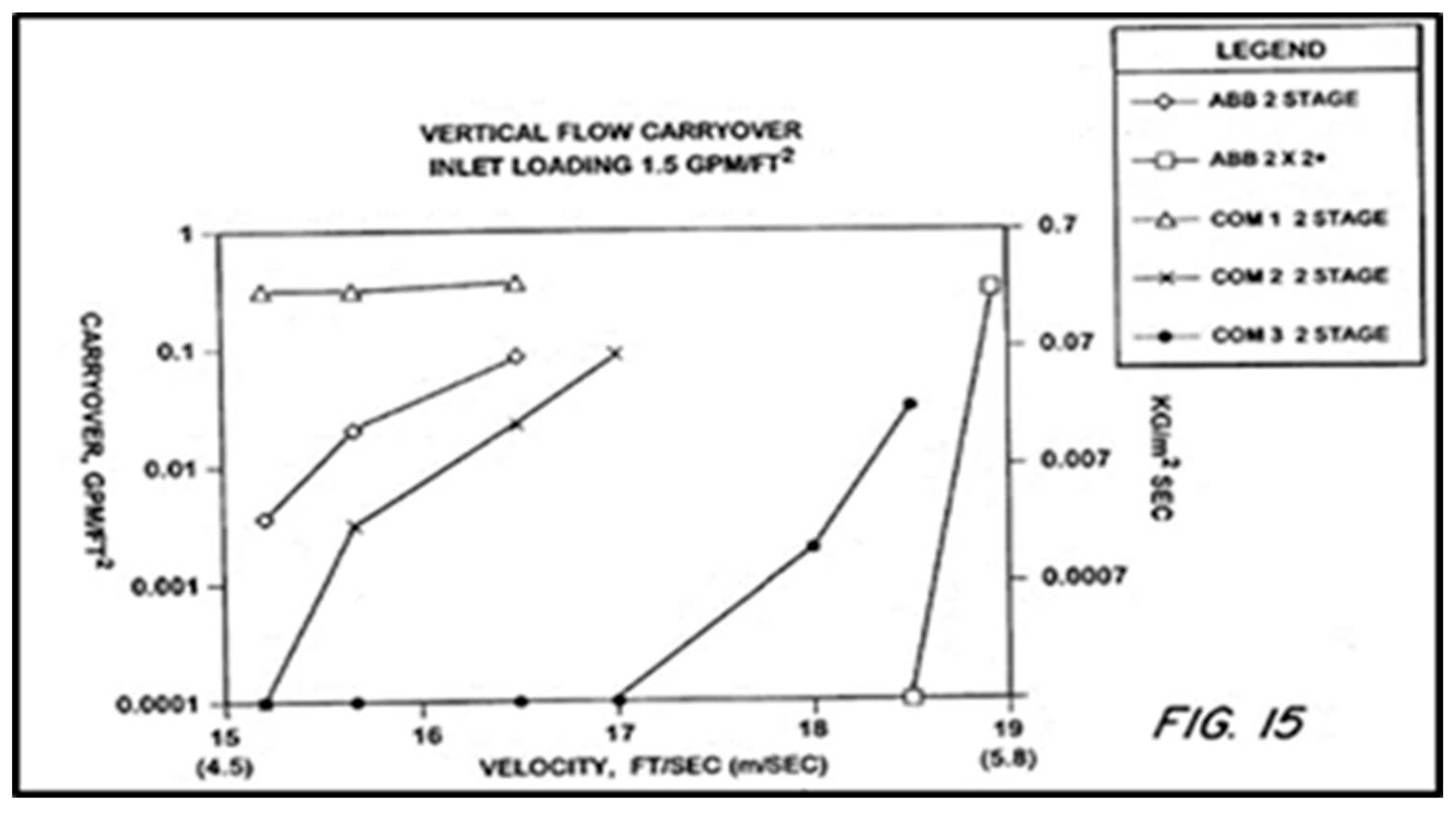
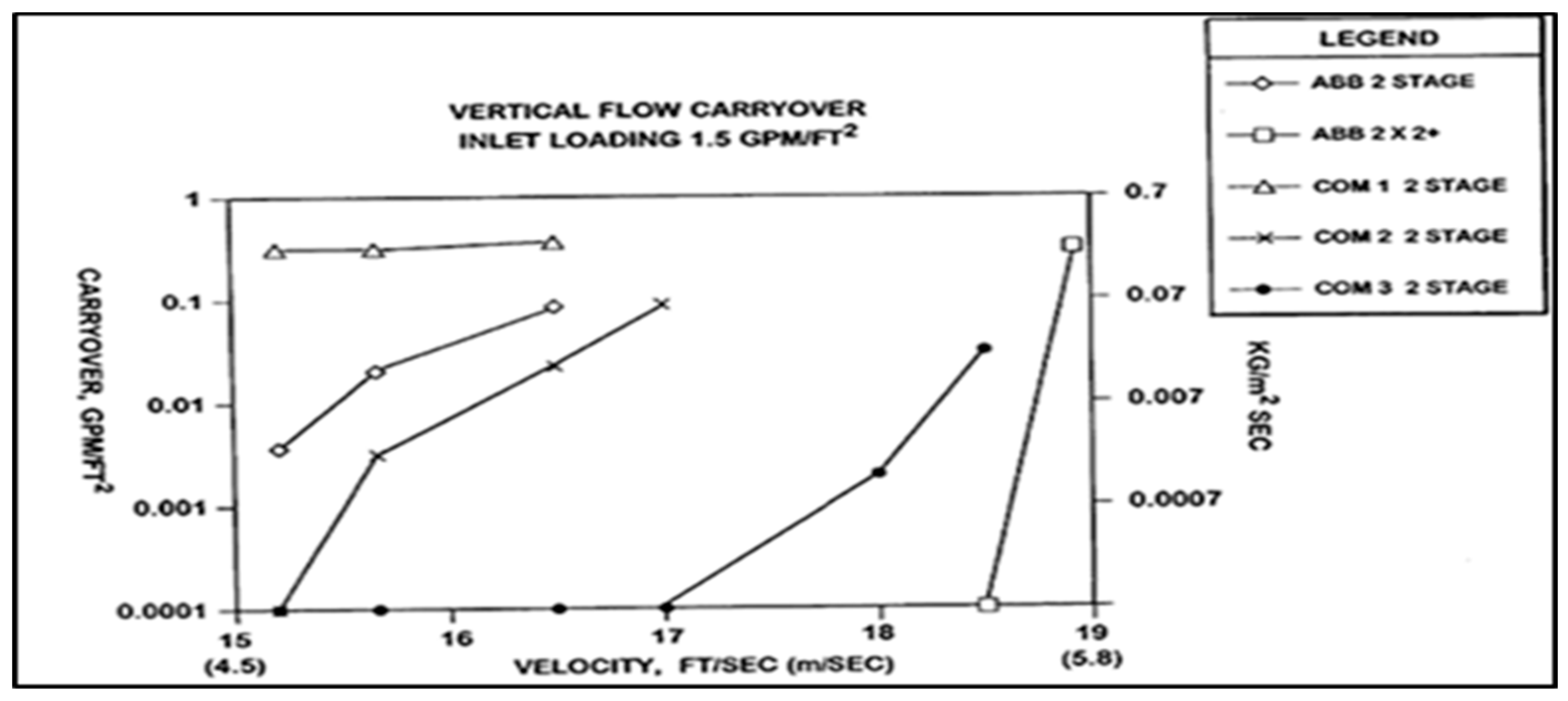
Figure 13 presents the results of the tests for a vertical airflow, that is, the results of the efficiency of collection of water droplets, the configuration analyzed is likewise two-stage with two steps with extension, represented as "ABB 2 STAGE."

3.2.1. Types of technologies evaluated

The process of evaluation and choice of the appropriate type of technology to provide technological support to the gas scrubber of the boiler # 10 of the CAVSA, three proposals were analyzed, detailed in Table 4. Proposals evaluated under the same parameters.

3.2.2. Decision Factors

For the selection of one of the proposals, the following decision factors were taken into account: maintenance costs, operation, air quality, energy consumption, occupied area, ease of implementation and use.
The factors were assigned a relative weight based on their importance, three for the highest score, which indicates a high degree of incidence. Then two, intermediate level that may or may not have an impact and, finally, 1, which indicates that it does not have a great impact at the time of selecting the appropriate proposal. Look at Table 5:

3.2.3. Evaluation Matrix

The evaluation matrix, as well as the decision factors and relative weights determine the comparison sheet see Table 6. The technologies based on the decision factors were scored on a scale of 1 to 5, assigned according to assessments deduced by the researcher, which have a total score that comes from the multiplication of the assigned score by the relative weight of each decision factor, this led to that through the summation a minimum margin of error is obtained allowing you to choose the most appropriate and viable option, for the present research it was the Chevron type fog eliminator, since with a total score of 47, it obtained the highest score based on the technical aspects analyzed.

3.2.4. Design and construction of the fog eliminator

After comparison and analysis by means of indicators, additional equipment is designed. Based on the characteristics of the gas scrubber, it proposes to improve ash capture with an economical device to manufacture, easy installation and maintenance. The study mentions that "mist eliminators are widely used in the chemical, oil and gas industry, to capture liquid droplets from the flow of a gas or vapor, another reason for the use of fog eliminators is to restrict emissions of pollutants to the environment, to prevent corrosion damage of equipment " [8].
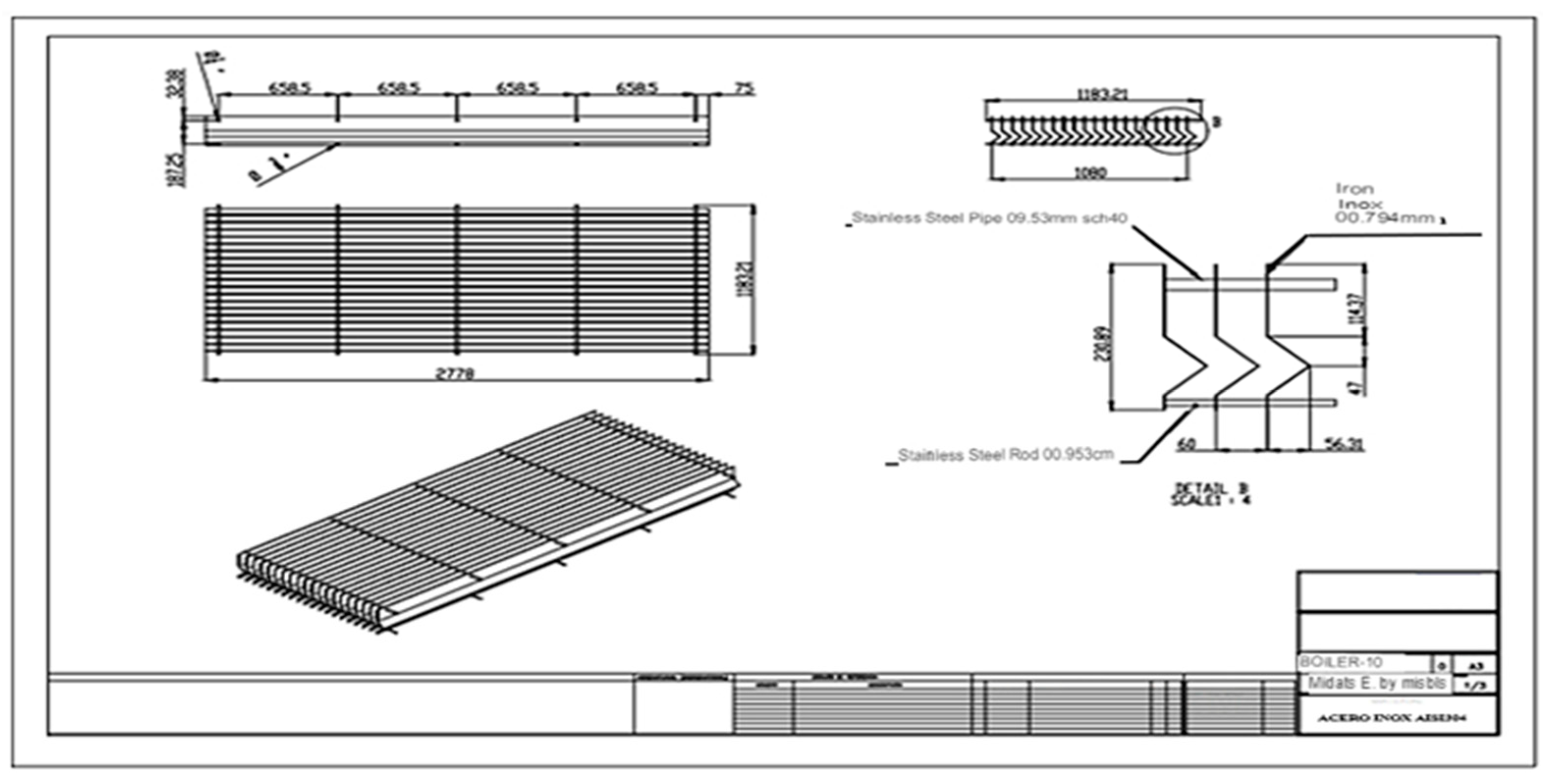
For the design of the Chevron type fog eliminator module, see Figure 14, the following materials made of AISI 304 stainless steel were used: 0.7938 mm thick sheets, Ø 9.525 mm pipes and Ø 9.525 mm rods. The area of the module has the following dimensions: length 2,778 mm and width 1,183.21 mm.
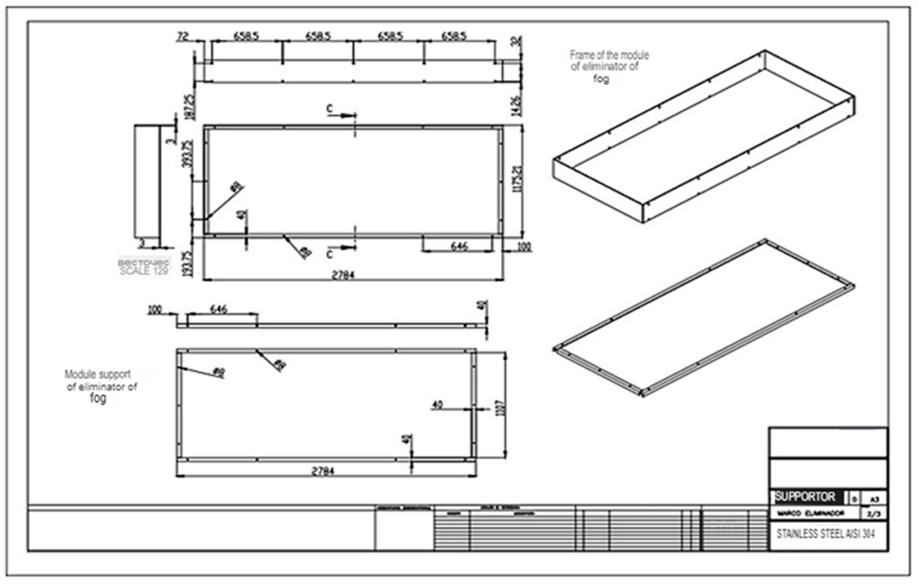
In the design of the frame-support, see Figure 15, the fog eliminator module takes into account the following measurements: length 2,784 mm x width 1,175.21 mm, while for the support of the same: 2784 mm x 1107 mm.
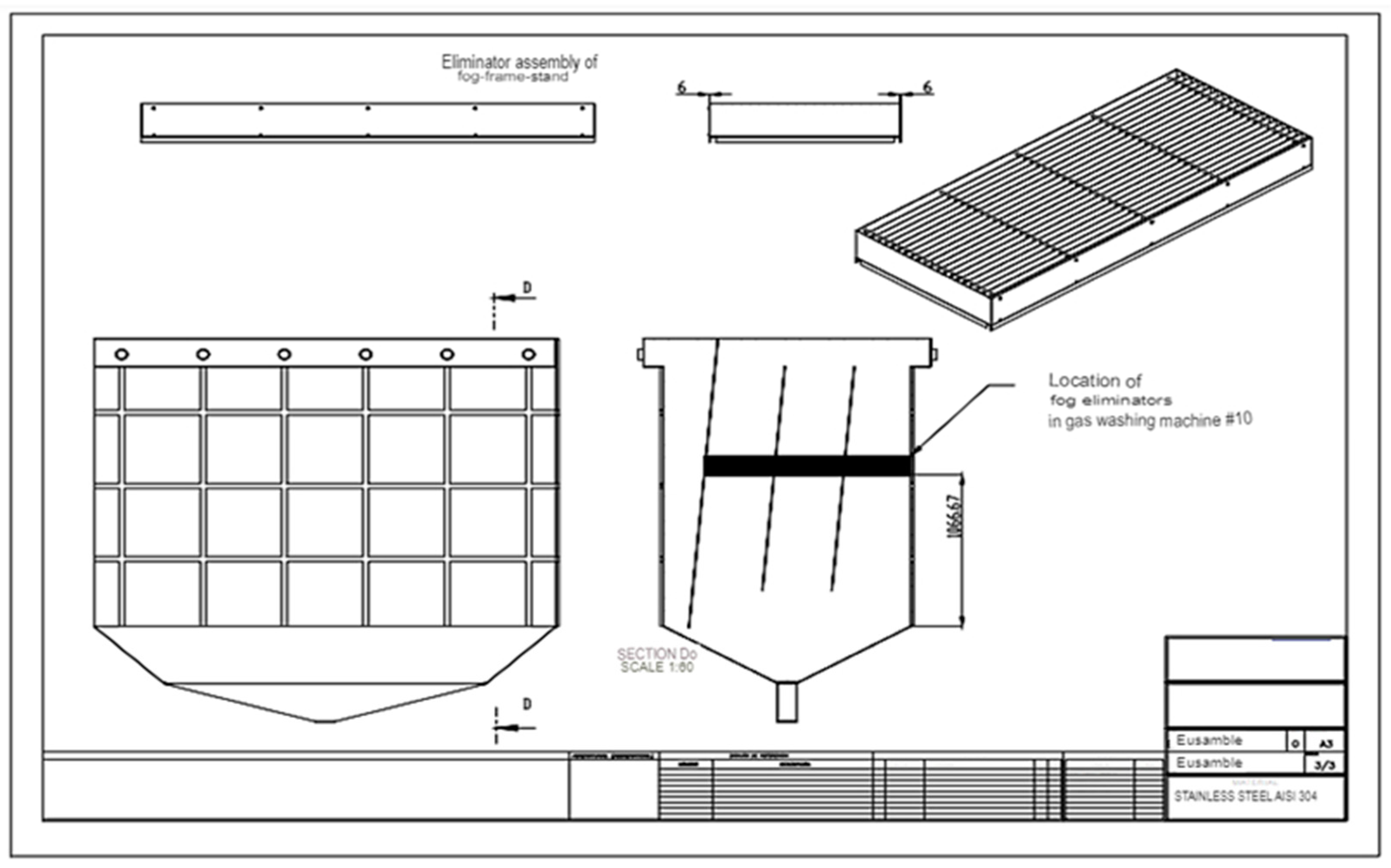
Designed the module, frame and support of the fog eliminator, we proceed to the construction of the same, in Figure 16 you can see, the location that will have inside the gas scrubber.
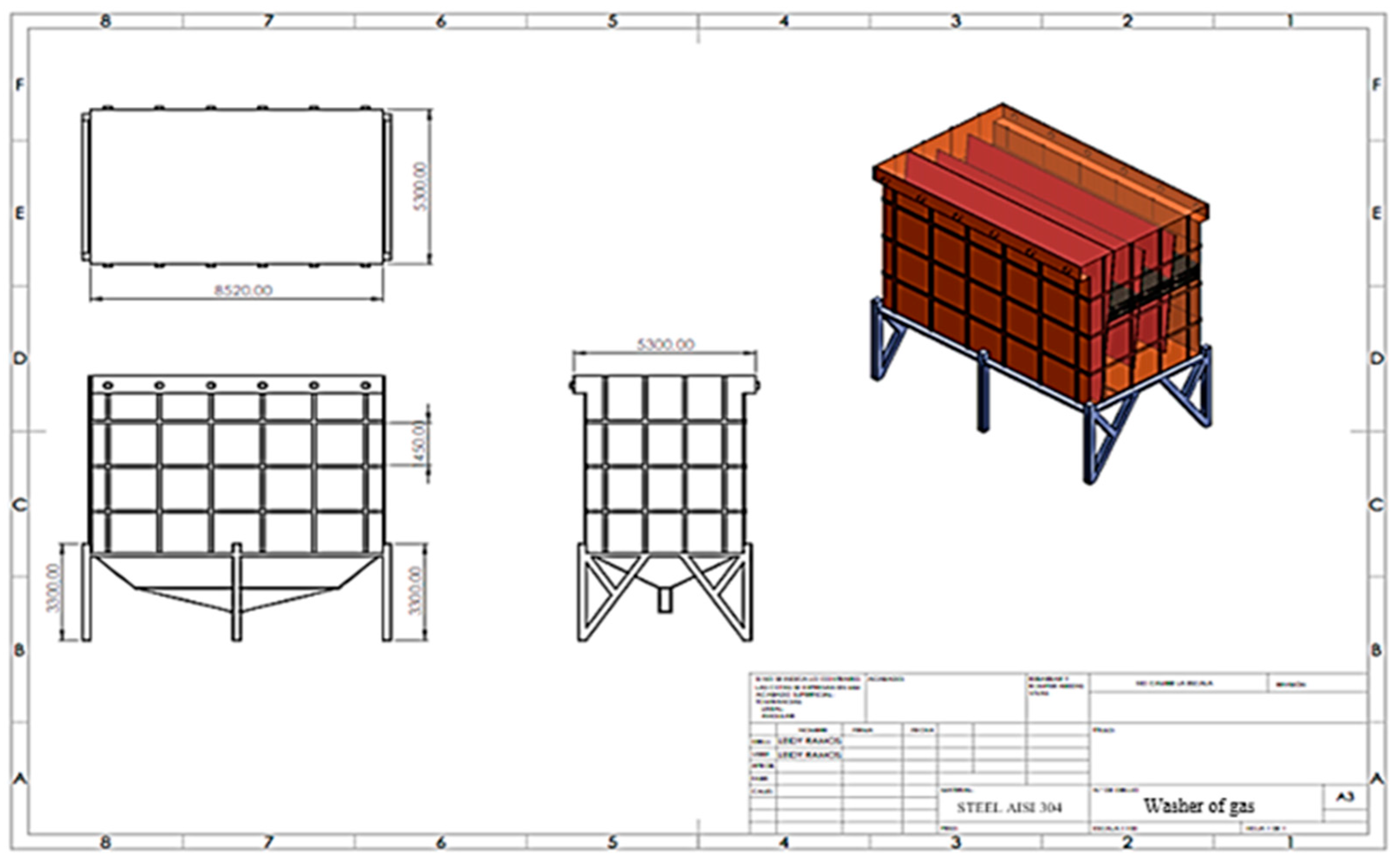
Figure 17 shows in 3D the mist eliminator in the gas scrubber.

3.2.5. Implementation costs

The costs of the design and implementation of the project are exposed in the following tables that contain: Labor costs, materials and, the total cost of the project.
Table 7 shows the labor costs, specifying activities to be performed, number of times, unit weights, total weights, average costs per activity and the total cost.
Table 8 indicates the materials needed to build the fog eliminator design, the quantity, the price, the cost per order and the total materials.
Table 9 shows the values for each kg of material contributed.

3.2.6. Analysis of NPV and TIR, and finally the ROI for the CAVSA.

The investment, income, expenses and discount rate are projected. As income takes as a reference, the cost to take out of operation one day the water-tube cauldron # 10, value that is $ 160,000 and, to determine the expenses, takes the cost of production of the presentation of sugar (50Kg), whose value is 65% of the sales price. Calculations for a period of 5 years, Look at Table 10:
The calculation of NPV and IRR was performed using direct formulas in Excel.
NPV=BPU-Investment; where, BPU is the sum of the present value of the cash flow, which is discounted through the discount rate.
P r e s e n t   v a l u e   o f   c a s h   f l o w = N e t   c a s h   f l o w ( 1 + D i s c o u n t   r a t e ) P e r i o d
Given Table 11 result, In this case the NPV is a positive value which indicates the profit that will be obtained after discounting the initial investment. That is, the project is viable.
The internal rate of return (IRR) indicates that the project has a profitability of 95%.

3.2.7. ROI analysis or payback period

This analysis allows us to know the estimated time in which the initial investment would be recovered. Look at Table 12.
In this case, the payback period of the initial investment will be in 11 months and one day.

3.2.8. Discussion of results

Figure 18 represents the results of the tests, for a vertical airflow, that is the results of the water droplet collection efficiency, the configuration analyzed is likewise two-stage with two steps with extension, represented in Figure 18 as (ABB 2 STAGE)
The results obtained for the models in the vertical flow indicate that the two-stage fog eliminator with two steps (ABB 2 STAGE) has an approximate efficiency of 0.034 Kg/s*m² as shown in Figure 18 at an approximate speed of 4.62 m/s, indicates that of the inlet load = 1.02 Kg/s*m², only 0.034 Kg/s*m² is not caught.
It was estimated according to the results, that a 1-stage 2-step eliminator configuration, a collection efficiency of 0.0068 Kg/s*m².
The load to which the system will be subjected is determined as follows:
Liquid load:1.67 m³/min
Cross-sectional area of fog eliminators: 24.81 m²
Load in:1,12 Kg/s*m²
Estimated water drag 20% of load: 0.22 Kg/s*m²
Table 13 shows the results for the mist eliminator that was designed, which indicates that it would have a collection efficiency of 99.39%, significantly reducing emissions of particulate matter into the atmosphere.
Table 14 compares the data obtained in the study carried out in 1996, with the estimated efficiency to be obtained, incorporating the mist eliminator to the original gas scrubber.

4. Conclusions

  • The environmental pollution generated by the water-tube cauldrons of the CAVSA, affects approximately 5000 people who live within the Chirijos-Milagro neighborhood, located 500 meters from the chimneys, despite having gas scrubbers that have an ash collection efficiency of the order of 95%, they are not enough to mitigate the permanent particulate matter during the harvest seasons towards the atmosphere.
  • To optimize the current wet gas scrubber system, it was essential to know the incidence of the variables that were part of the system such as; Type and amount of pollutant that is produced and emitted into the environment.
  • The design of the Chevron type mist eliminator type (ABB 2 STAGE), incorporated into the original gas scrubber of the cauldron, aims to optimize the collection of ash increased by 4.39% with respect to the original efficiency, achieving the capture of 23487000 kilograms of additional ash during the harvest period.
  • The nozzles that are in abrasive contact with the ash and, subjected to wear of the external surface causing cracks and damage, to avoid this, the researcher suggests making an epoxy coating, ceramic or with one or two sheets of stainless steel 304 of 0.0794 cm thickness as sacrificial sheet to preserve them.
  • In Ecuador there are sufficient laws, standards and environmental regulations, but it does not have a regime or legal audits, which control and regulate the operation of industrial processes, which cause polluting emissions and can be observed or punished.
  • The design, construction and installation of devices for the control of emissions do not have direct economic benefits, their economic evaluation is carried out through the non-payment of environmental fines or industrial stoppages, which may be caused by insurgent uprisings of those affected, noticing in the short term the economic benefits indirectly.
  • The operating costs per harvest of a proposed system are low, due to the consumption of water and energy ($2000) compared to the design, construction and assembly of equipment such as Chevron type fog eliminator (ABB 2 STAGE) ($10000 approx.).

5. Limitations

Limitations include: cost, the need for an adequate power source for operation, the amount of space available for installation, regular maintenance and cleaning requirements, as well as the need for good ventilation to prevent the accumulation of toxic gases.

6. Implications

It is possible to implement this design and construction of the fog eliminator to the other water-tube cauldrons of the CAVSA, achieving better efficiencies of them, since they are cauldrons that have a higher percentage of operation within the generation of steam during harvest, globally the efficiency of the current gas scrubbers would increase by 3% reaching 98% in total. This is important to reduce particulate pollution into the atmosphere.
It can be transcended with this research and directed to the Ecuadorian and international sugar industry, with training to develop cognitive processes, entrepreneurship training would prioritize the formation of holistic skills (emotional aspect) to later structure rational thinking with more technical topics such as innovation and prospecting. This contribution would argue the high impact that holistic training could have in the Ecuadorian sector in order to achieve greater adaptation of education (UNESCO-IESALC, 2020).

References

  1. Tapia Núñez, Lorena. Air emission standards from stationary sources.2015 Nov. Available online: https://maeorellana.files.wordpress.com/2015/11/anexo-3aire-fuentes-fijas.pdf.
  2. [EPA air pollution control cost manual [Book]. (D. C. Mussatti, Ed.) Research Triangle Park, NC 27711, North Carolina, Estados Unidos: Air Quality Strategies and Standards Division of the Office of Air Quality Planning and Standards, U.S. 2002. Available online: https://www3.epa.gov/ttncatc1/cica/files/c_allchs-s.pdf.
  3. China Chevron Vane Type Mist Eliminator Suppliers, Manufacturers—Wholesale price—YUANFENG. (n.d.). Wuxi Anaya Environmental Protection Technology Co., Ltd. (2001). [Internet]. Available online: https://es.yfenvironment.com/mist-eliminator/chevron-vane-type-mist eliminator.html.
  4. Ramos Núñez and Mendoza Haro. Environmental sustainability, optimization of the gas scrubber for water-tube boilers in Compañía Azucarera Valdez S.A. [Thesis]. Milagro: Unemi Repository, Milagro State University "UNEMI"; 2021 May; (13-56). Available online: https://repositorio.unemi.edu.ec/bitstream/123456789/5583/1/Ramos%20Nu%C3%B1ez%20Leidy%20Jocelyne.pdf.
  5. Lobato Freire GE, Castillo Castillo ÁF. Design and construction of a cyclonic separator with tangential input and axial discharge for particulate matter smaller than 40 um [Internet]. dspace.espoch.edu.ec. 2015. Available online: http://dspace.espoch.edu.ec/handle/123456789/4852 (accessed on 23 June 2023).
  6. Rahimi R, Abbaspour D. Determination of pressure drop in wire mesh mist eliminator by CFD. Chemical Engineering and Processing: Process Intensification. 2008 Sep;47(9-10):1504–8. Available online: https://www.sciencedirect.com/science/article/abs/pii/S0255270107002206.
  7. Narimani E, Shahhoseini S. Optimization of vane mist eliminators. Applied Thermal Engineering. 2011 Feb;31(2-3):188–93. Available online: https://www.sciencedirect.com/science/article/abs/pii/S1359431110003741.
  8. Galletti C, Brunazzi E, Tognotti L. A numerical model for gas flow and droplet motion in wave-plate mist eliminators with drainage channels. Chemical Engineering Science. 2008 Dec;63(23):5639–52. Available online: https://www.sciencedirect.com/science/article/abs/pii/S0009250908004314.
  9. Rafeea R, Rahimzadeh H, Ahmadi G. Numerical simulations of airflow and droplet transport in a wave-plate mist eliminator. Chemical Engineering Research and Design. 2010 Oct;88(10):1393–404. Available online: https://www.sciencedirect.com/science/article/abs/pii/S0263876210000912.
  10. Hernández SAmpieri, R; Fernandez &. Baptist. Research methodology. 6 ed. Mexico City: McGRAW-HILL / INTERAMERICANA EDITORES, S.A. DE C.V. 2010. [Digital book]. Available online: https://www.uca.ac.cr/wp-content/uploads/2017/10/Investigacion.pdf.
  11. Tashakkori A, Creswell JW. Editorial: Exploring the Nature of Research Questions in Mixed Methods Research. Journal of Mixed Methods Research. 2007 Jul;1(3):207–11. Available online: https://journals.sagepub.com/doi/pdf/10.1177/1558689807302814.
  12. Castiñeiras S. How to calculate a droplet separator [Internet]. Collaborative Engineering. Available online: https://ingenieriacolaborativa.com/separador-de-gotas/ (accessed on 23 June 2023).
  13. Cao X, Bian J. Supersonic separation technology for natural gas processing: A review. Chemical Engineering and Processing - Process Intensification. 2019 Feb; 136:138–51. [CrossRef]
  14. Wang S, Li H, Wang R, Wang X, Tian R, Sun Q. Effect of the inlet angle on the performance of a cyclone separator using CFD-DEM. Advanced Powder Technology [Internet]. 2019 Feb 1 [cited 2022 May 10];30(2):227–39. Available online: https://www.sciencedirect.com/science/article/abs/pii/S0921883118308173.
  15. Wasilewski M, Brar LS. Effect of the inlet duct angle on the performance of cyclone separators. Separation and Purification Technology. 2019 Apr;213:19–33. [CrossRef]
  16. Bahadori A. Natural Gas Processing: Technology and Engineering Design [Internet]. Google Books. Gulf Professional Publishing; 2014. Available online: https://books.google.com.ec/books/about/Natural_Gas_Processing.html?id=-cffoQEACAAJ&redir_esc=y (accessed on 23 June 2023).
  17. Erdal FM, Shirazi SA. Local Velocity Measurements and Computational Fluid Dynamics (CFD) Simulations of Swirling Flow in a Cylindrical Cyclone Separator. Journal of Energy Resources Technology. 2004 Dec 1;126(4):326–33. [CrossRef]
  18. China Chevron Vane Type Mist Eliminator Suppliers, Manufacturers - Wholesale Price - YUANFENG [Internet]. Wuxi Yuanfeng Environmental Protection Technology Co., Ltd. Available online: https://es.yfenvironment.com/mist-eliminator/chevron-vane-type-mist-eliminator.html (accessed on 24 June 2023).
  19. ames PW, Azzopardi BJ, Wang Y, Hughes JP. A Model for Liquid Film Flow and Separation in a Wave-Plate Mist Eliminator. Chemical Engineering Research and Design. 2005 May;83(5):469–77. Available online: https://www.sciencedirect.com/science/article/abs/pii/S0263876205727246.
  20. Bauver IWP, Anderson DK, Kingston WH. Mist eliminator for wet gas scrubbing [Internet]. Estados Unidos Patente nº 6,083,302. Available online: https://patents.google.com/patent/US6083302A/en (accessed on 23 June 2023).
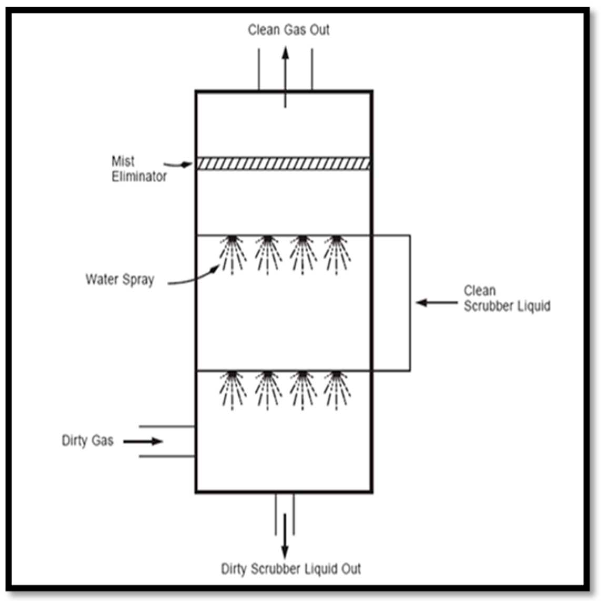
Figure 1. Gas scrubber scheme.
Preprints 83801 g001
Figure 2. Spray tower scheme with nozzles (Contaminants in gaseous effluents (and III) – Estrucplan [Internet]. Available from: https://estrucplan.com.ar/contaminantes-en-efluentes-gaseosos-y-iii/).
Preprints 83801 g002
Figure 3. Diagram of estimated flue gas velocities in scrubber, Source: own elaboration.
Preprints 83801 g003
Figure 4. Diagram of ideal flue gas velocities in scrubber, Source: own elaboration.
Preprints 83801 g004
Figure 5. Demister Mist Eliminator [12].
Preprints 83801 g005
Figure 6. Schematic diagram of the gas-liquid cyclone separator [17].
Preprints 83801 g006
Figure 7. Chevron Palette Mist Eliminator [18].
Preprints 83801 g007
Figure 8. Graphics of the different views of the pipe: (a) View of the Ø 19.05mm" pipe in nozzles and (b) View of the nozzle orifice. Source: Own Elaboration.
Preprints 83801 g008
Figure 9. Representación gráfica del perfil del cono formado por el rociador a diferentes presiones; Source: own elaboration.
Preprints 83801 g009
Figure 10. Comparative graphs of the prediction of efficiency of removal of liquid droplets with experiments: (a) Gas velocity 1 m/s; (b) gas velocity of 2 m/s and (c) gas velocity of 5 m/s [9].
Preprints 83801 g010
Figure 11. Figure footer: Nomenclature of the profile dimensions for fog eliminator [9].
Preprints 83801 g011
Figure 12. Representation of the test performed on the test bench for horizontal flow [20].
Preprints 83801 g012
Figure 13. Graphical representation of the test performed on the flow test bench [20].
Preprints 83801 g013
Figure 14. Module Design: Chevron Type Mist Eliminator for CAVSA Cauldron #10.
Preprints 83801 g014
Figure 15. Design of the support structure; Source: Authors.
Preprints 83801 g015
Figure 16. Ensambles módulo y estructura soporte.
Preprints 83801 g016
Figure 17. Final design gas scrubber containing Chevron type mist eliminator.
Preprints 83801 g017
Figure 18. Test performed on the test bench for vertical flow [20].
Preprints 83801 g018
Table 1. Characterization of washing showers.
Pressure [Kg/cm2] Cono radius [cm] Height [cm] Cone thickness [cm]
1,4062 53.34
83.82
119.38
50
100
157
17.78
17.78
17.78
2,1092 53.34
83.82
116.84
50
100
157
20.32
20.32
20.32
2,8123 53.34
83.82
116.84
50
100
157
20.32
20.32
20.32
3,9372 53.34
83.82
119.38
50
100
157
22.86
22.86
22.86
Table 2. Percentage of liquid trapped in each curve [19].
Preprints 83801 i001
Table 3. Dimensions of the profile of the sheets for the mist eliminator.
Nomenclature Dimensions [mm]
a
b
c
d
230.89
56.31
101.36
22.52
Nomenclature Dimensions [mm]
Table 4. Technologies.
N.- Technologies
1
2
3
Demister Mist Eliminator
Cyclone fog eliminator
Chevron type fog eliminator
Table 5. Relative weight of decision factors.
Decision factor Relative weight
Maintenance and operation costs 3
Air quality 3
Power consumption 2
Occupied area 1
Ease of use and deployment 1
Table 6. Comparison Table – Own Elaboration.
Preprints 83801 i002
Preprints 83801 i003
Table 7. Labor costs of the fog eliminator.
Workmanship for two-step fog eliminator
Description Unit Unit weight (kg) Total weight (kg) Average cost ($) Total cost ($)
Layout and assembly of fog eliminator blades of 0.0794cm x 0.305 m x 2.779 180 5.29 952.20 0.80 761.76
Folding of blades to form a profile of 0.0794cm (according to plane) 540 5.29 2856.60 0.25 714.15
Drilling holes for pipe of Ø0.953cm in blades (according to drawing) 855 1.00 855.00 0.25 213.75
Drilling of holes for rod of Ø0.953cm in blades (according to drawing) 855 1.00 855.00 0.25 213.75
Layout and assembly of stainless steel support pipes for fog eliminator blades of Ø0.953cm cedula 40 x 1.169 m 9 4.90 44.10 1.60 70.56
Layout and assembly of stainless steel support rod for fog eliminator blades of Ø0.953 cm x 1.169 m 9 2.19 19.71 1.60 31.54
Layout and assembly of fog eliminator support frame 0.231 m x 2,785 m x 1,179 m 9 65.18 586.60 0.80 469.28
Layout and assembly of fog eliminator support with 40 mm Stainless steel angle. 9 14.64 131.79 0.80 105.43
Total 6301 Total ($) 2580
Table 8. Materials for the design of the fog eliminator.
Materials for the two-step mist eliminator
Description Quantity Price ($ c/u) Total Average cost of ordering ($) Total Cost ($)
Planchas Inox AISI 304 121.92 cm x 243.84 cm por 0.079375 cm 180 kg 5.29 952.20 3.05 2901.35
Planchas Inox AISI 304 of 0.3175 cm 9 kg 65.18 586.60 3.17 1858.94
Stainless steel pipe AISI 304 of 0.9525 cm cedula 40 9 kg 5.85 52.61 6.73 354.03
Varilla Stainless steel AISI 304 0.635 cm 9 kg 2.19 19.71 0.99 19.51
40 x 40 x 4 mm angle 9 m 7.91 71.17 10.17 723.82
Total ($) 5858
Table 9. Total cost of the proposal.
Team Total(kg) Unit cost ($) Total cost ($)
Workmanship for two-step mist eliminator with ext. 6301 $ 0.41 $ 2580
Materials for the two-step mist eliminator with ext. 1.00 $ 5857.66 $5858
Subtotal 6.301,00 $8438
10% $844
Total $9282
Table 10. Data to determine NPV and IRR.
Data
Initial investment 9 282
Discount rate 12%
Revenue 160000
Expenses 104000
Table 11. NPV and IRR calculation.
Period Revenue Expenses Net cash flows Present value of cash flow
0 -9282 -9282
1 32000 20800 11200 10000
2 32000 20800 11200 8928.57
3 32000 20800 11200 7971.94
4 32000 20800 11200 7117.80
5 32000 20800 11200 6355.18
Net Present Profit (BPU) 40373.49
Net present value (NPV) $1091.49
Internal rate of return (IRR) 95%
Table 12. Payback period.
Period Present value of cash flow Accumulated
0 -9282
1 10000 18928.57
2 8928.57 18928.57
3 7971.94 26900.51
4 7117.80 34018.31
5 6355.18 40373.49
Recovery period 0.92 years
Table 13. Collection efficiency.
Input charging (Kg/s*m²) Inlet load (l/min*m2) Efficiency (Kg/s*m²) Efficiency (l/min*m2) Accumulated
U.S. Study
1.5 61.1 0,005 0,204 99,96
Expected results in the proposal
1,12 67,2 0.008 0,407 99,39
Table 14. Expected results by implementing the fog eliminator.
Particulate emission (kg/h) Efficiency % Emission of particles into the atmosphere (kg/h) Harvest hours Particulate emission in the harvest period (kg)
Without the fog eliminator
891 95 44.6 4320 192519
With the fog eliminator
891 99.4 5.4 4320 23487
Disclaimer/Publisher’s Note: The statements, opinions and data contained in all publications are solely those of the individual author(s) and contributor(s) and not of MDPI and/or the editor(s). MDPI and/or the editor(s) disclaim responsibility for any injury to people or property resulting from any ideas, methods, instructions or products referred to in the content.
Copyright: This open access article is published under a Creative Commons CC BY 4.0 license, which permit the free download, distribution, and reuse, provided that the author and preprint are cited in any reuse.
Prerpints.org logo

Preprints.org is a free preprint server supported by MDPI in Basel, Switzerland.

Subscribe

© 2024 MDPI (Basel, Switzerland) unless otherwise stated