Submitted:
01 September 2023
Posted:
06 September 2023
You are already at the latest version
Abstract
Keywords:
1. Introduction
2. NBI purpose, scheme and structure
2.1. Neutral injection purpose
2.2. Neutral injection principles and scheme
2.3. Neutral beamline losses and efficiency
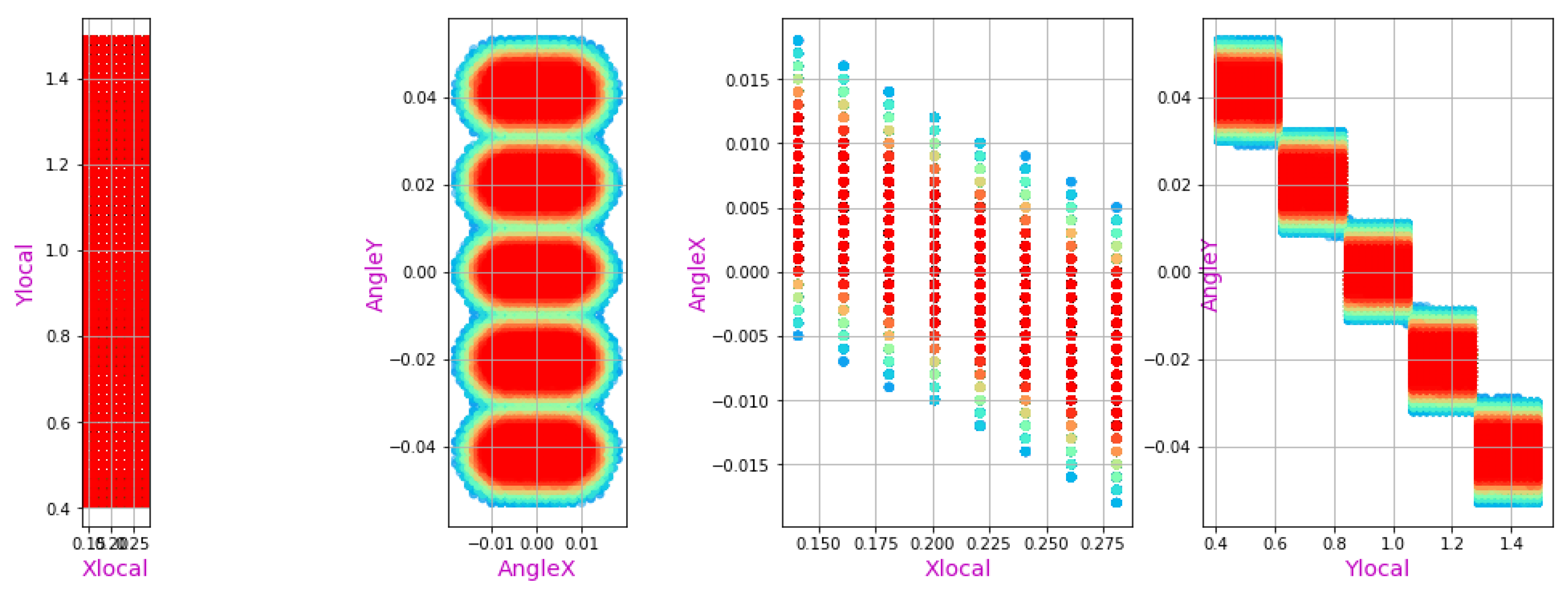
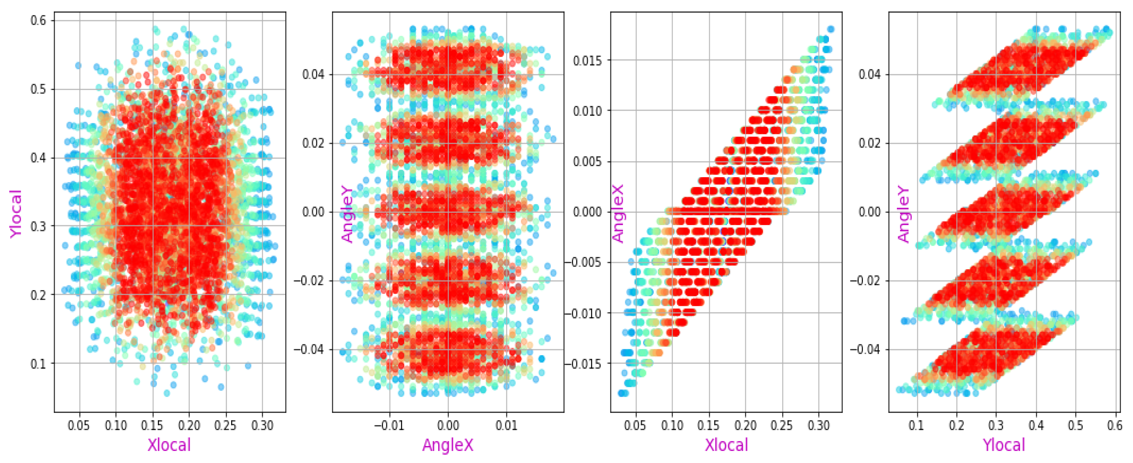
2.4. Neutral beamline geometry in BTR
- -
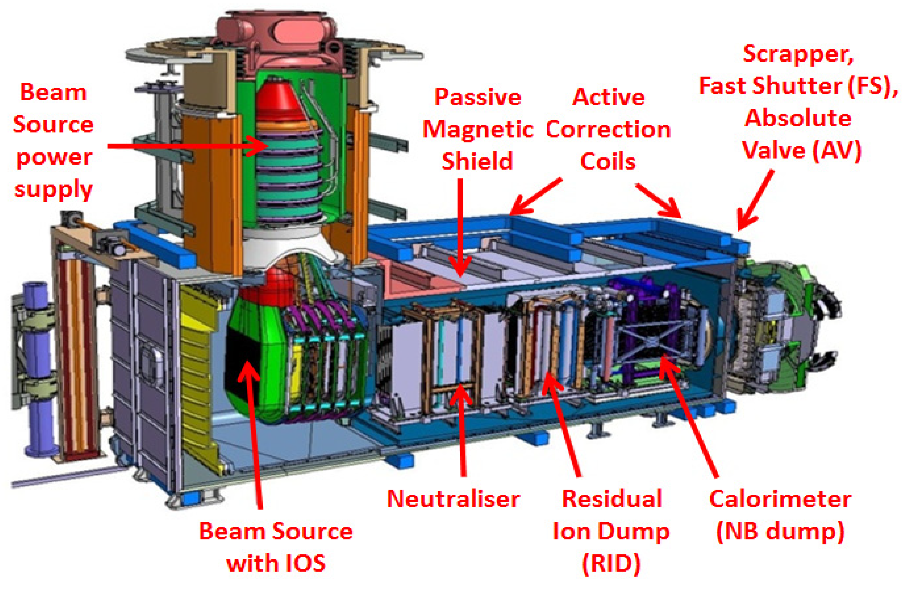
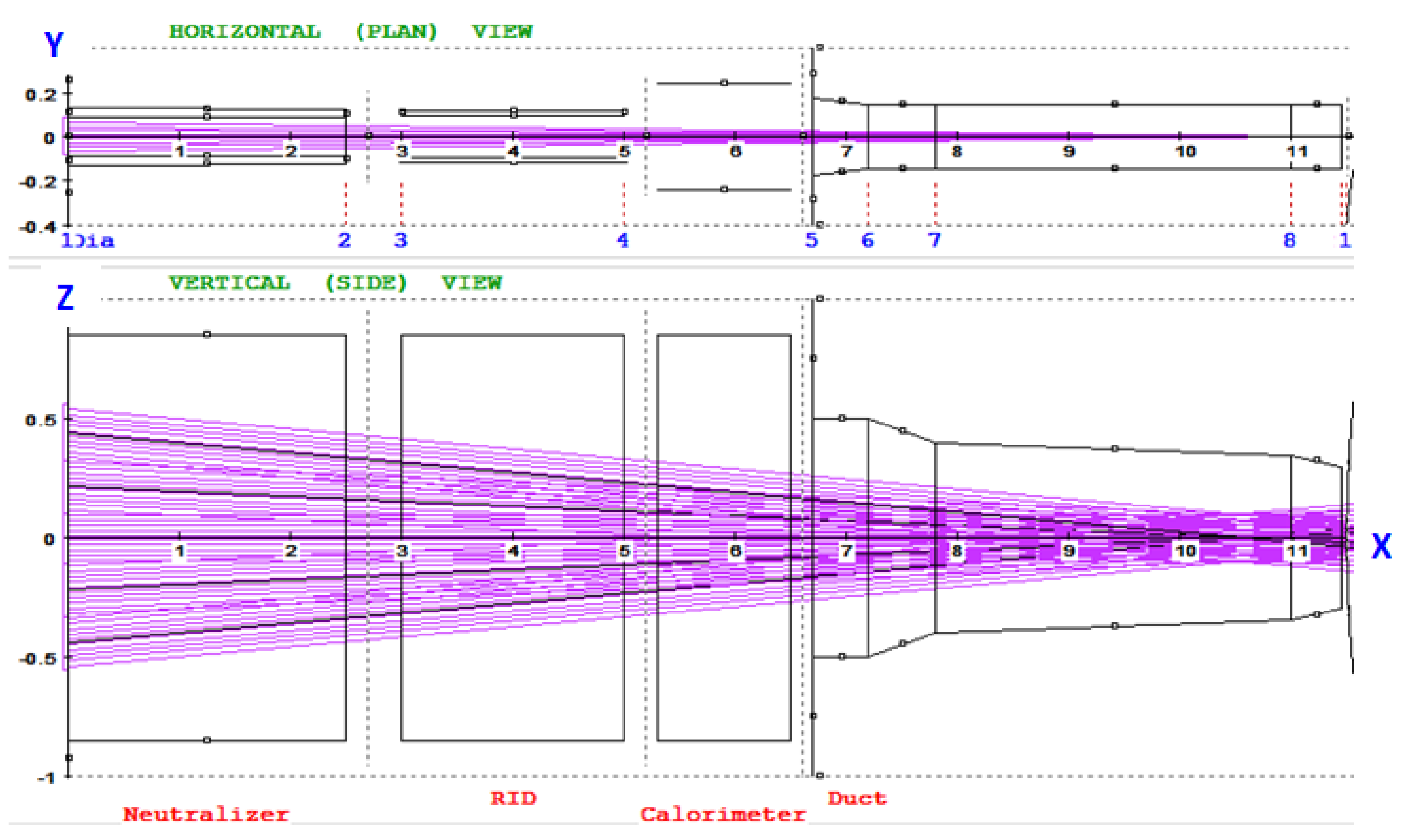
- the beam source grounded grid (GG),
- -
- multi-channel (can be single-channel) neutralizer,
- -
- residual ion dump, RID (multi- or single channel),
- -
- neutral beam dump, or calorimeter,
- -
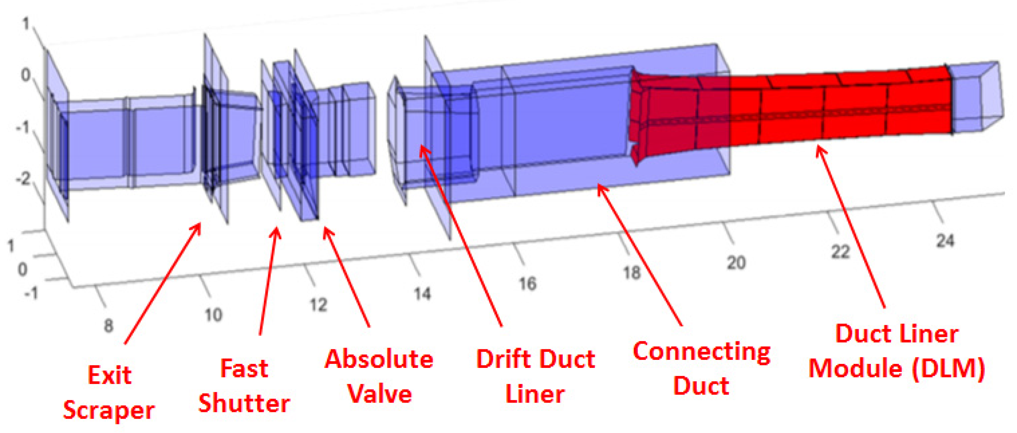
- beam transmission line, or duct, which consists of multiple modules (scrapers, FEC, liners, blanket sections, etc.).
3. BTR basic features and GUI
3.1. BTR general info
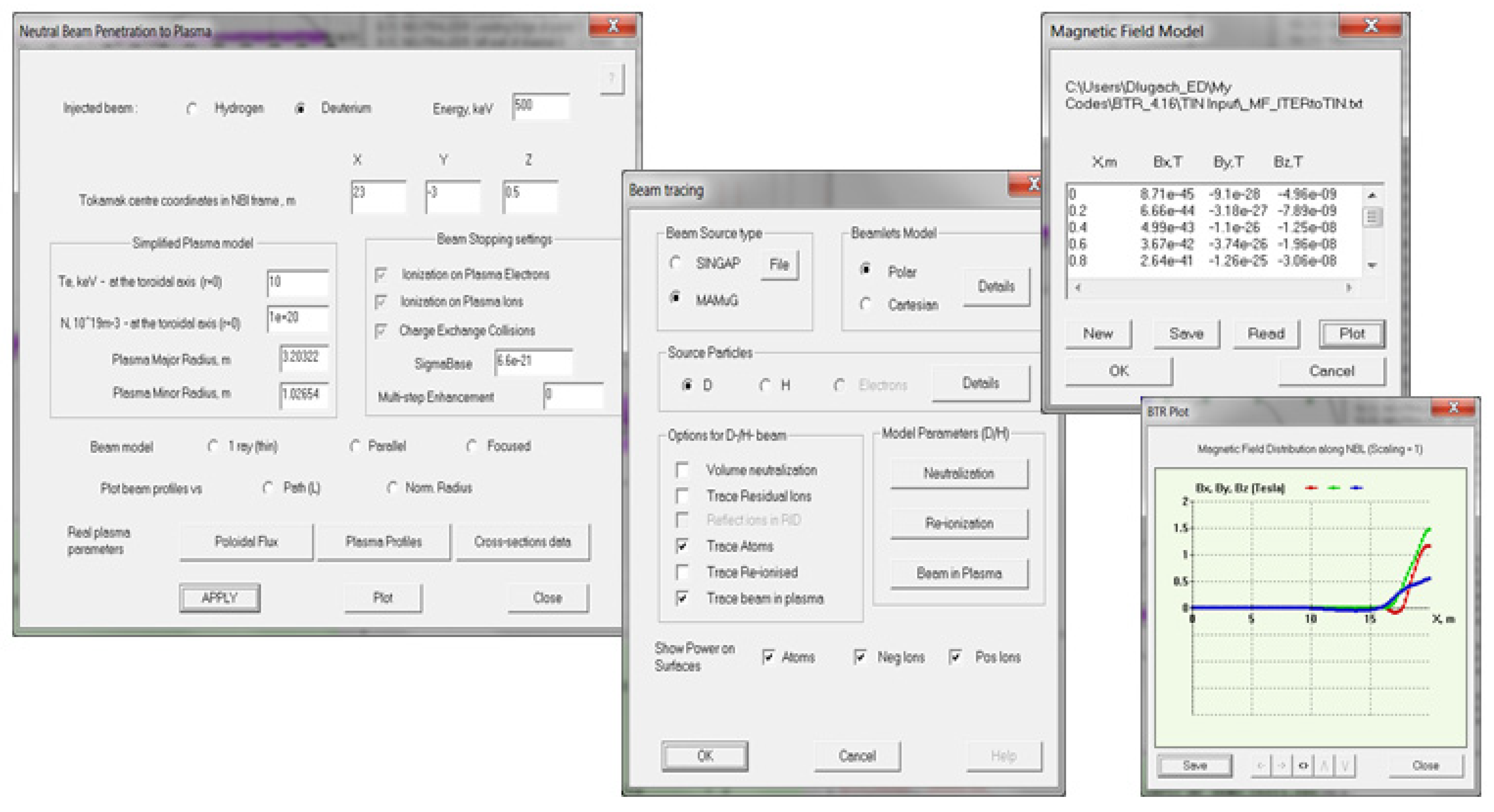
3.2. BTR User Interface
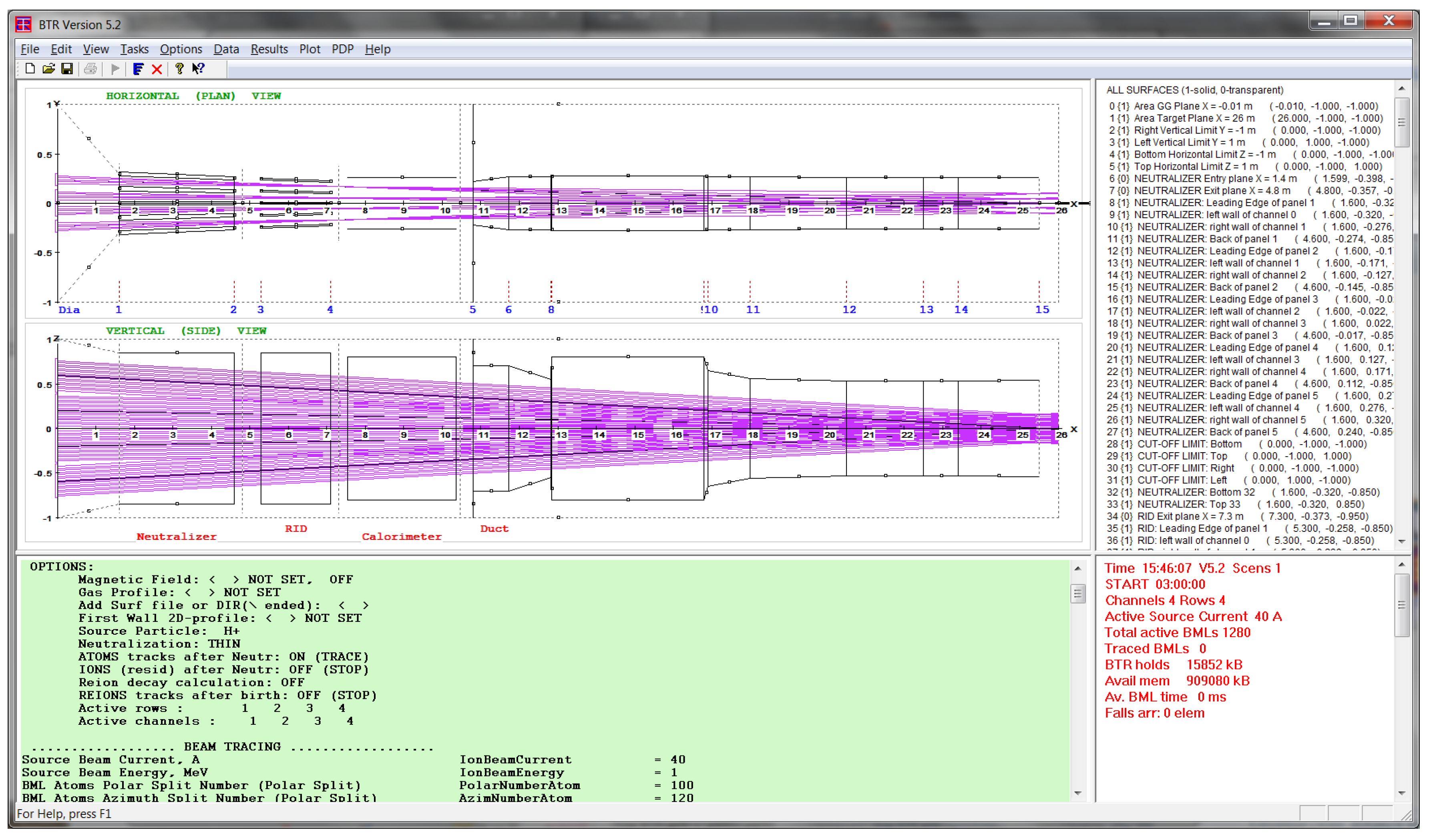
- “Config plot”, main view with NBI geometry and beam layout;
- “Green panel” tool - BTR interactive input data processor;
- “Loads Summary” / “Map” view switch;
- “Running Status” / “Profiles” view switch.
- -
- Update/Save/Import data;
- -
- Call dialogs for input by categories (i.e., alternative direct input way);
- -
- Define specific ‘Tasks’ and output options;
- -
- Add/Edit gas or field input profiles;
- -
- Select/manage visualization categories, and many other.
4. BTR models and tasks
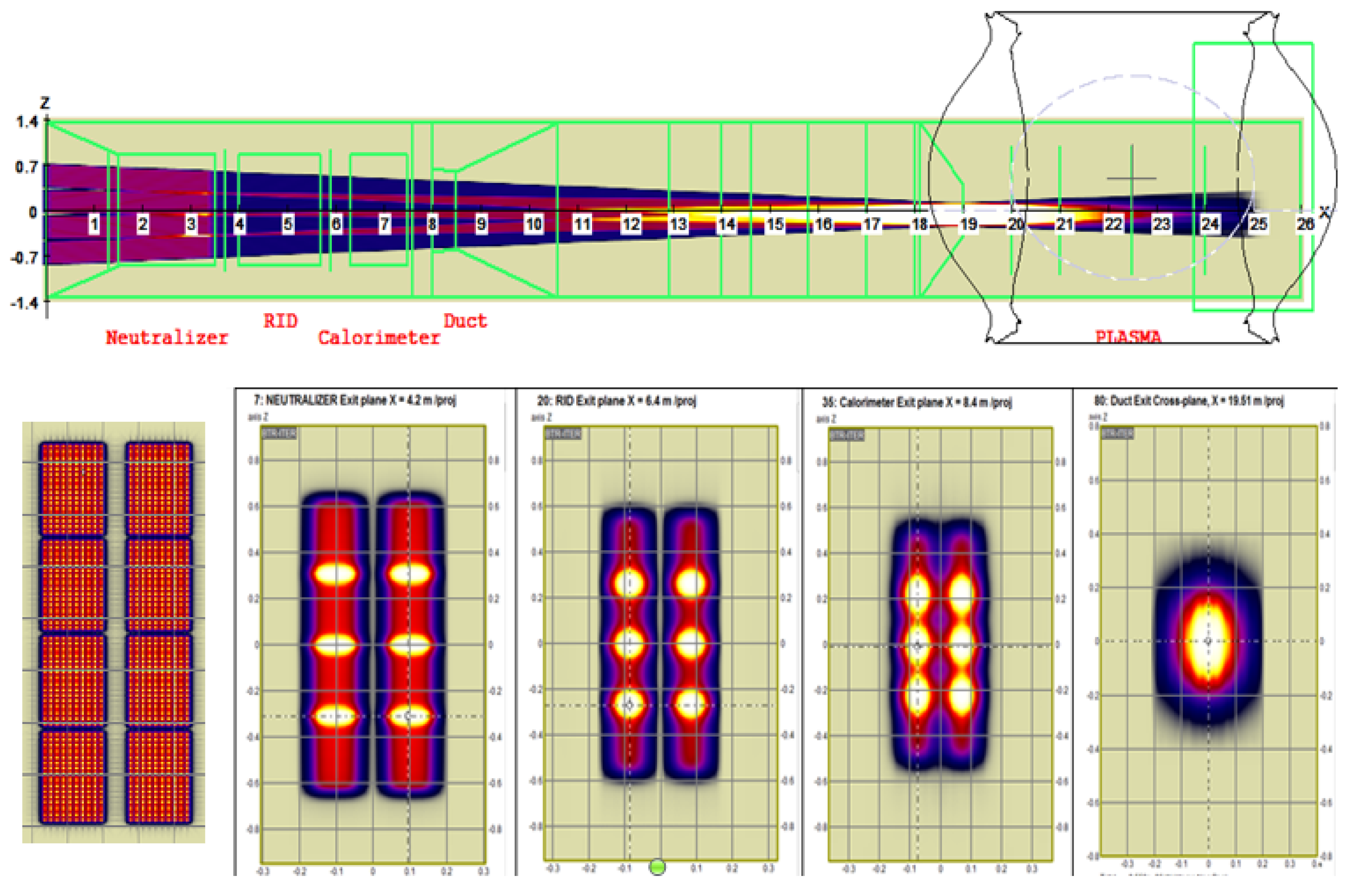
4.1. Beam shape and the injected power
4.2. Beam neutralization
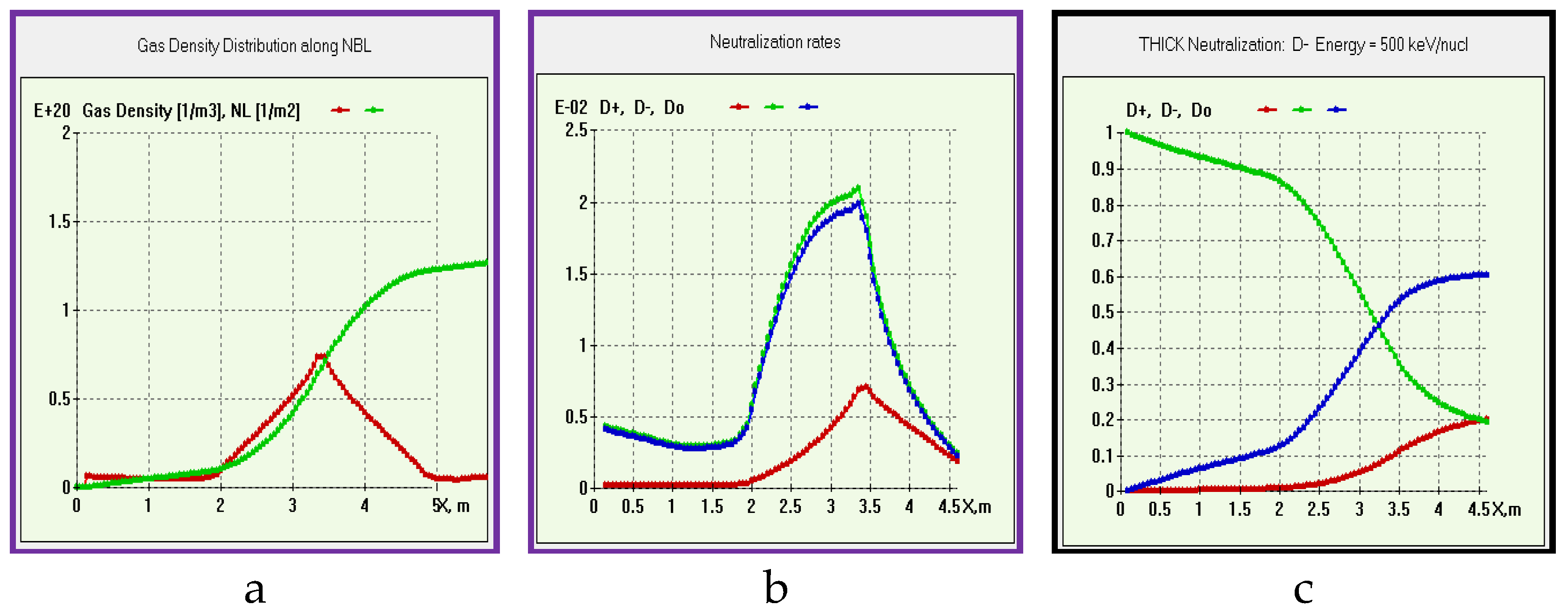
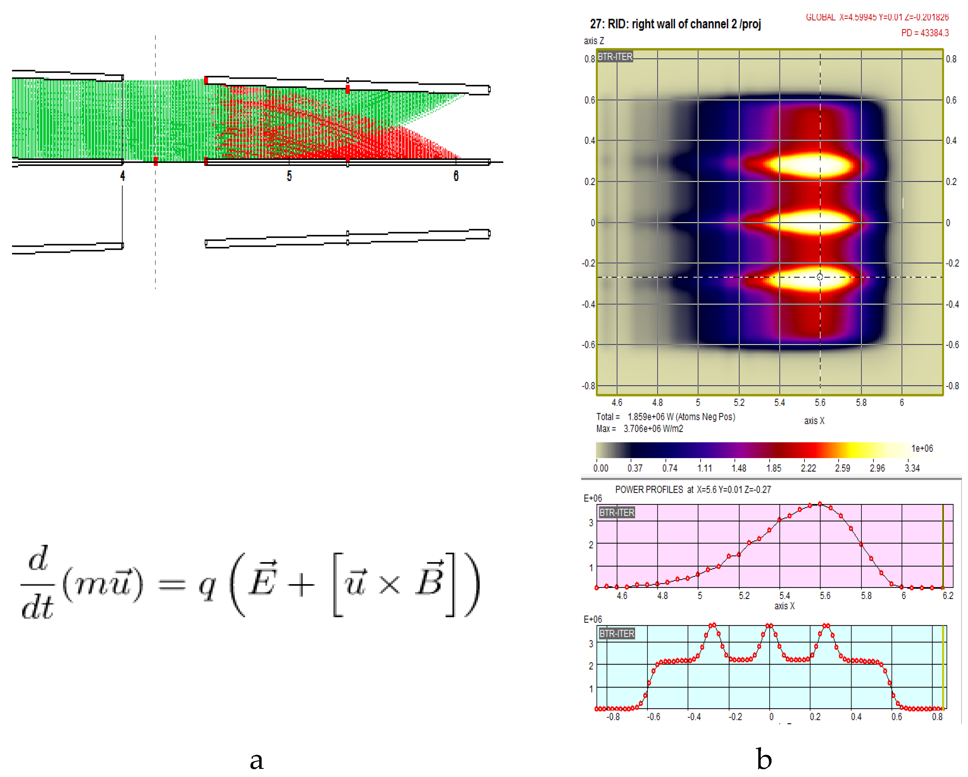
4.3. Residuals deflection and dumping
4.4. Re-ionisation on gas
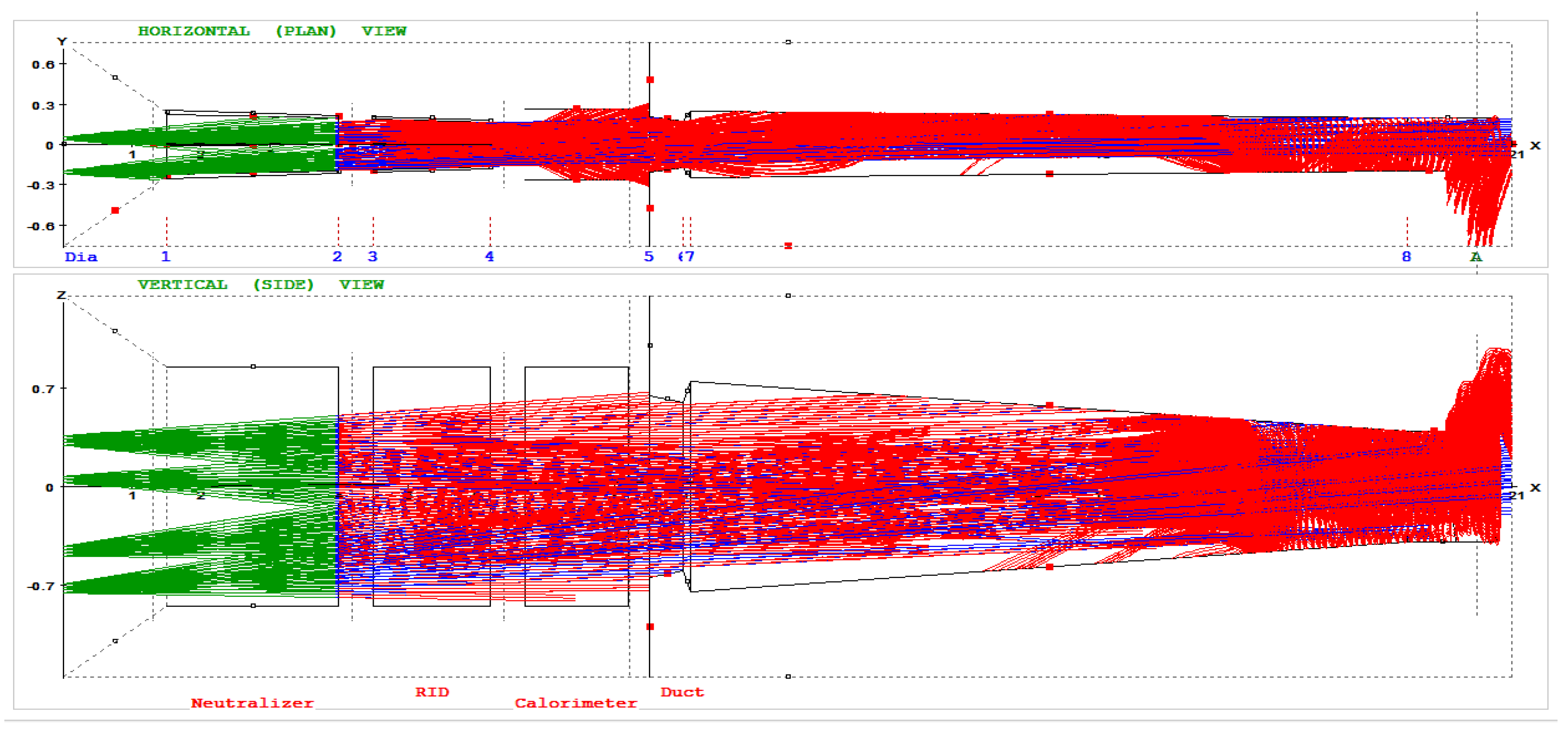
4.5. Penetration to tokamak plasma
4.6. Shine-through power at tokamak chamber wall
5. BTR verification
- Neutral particle tracks
- Charged particle motion in magnetic field
- Charged particle motion in electric field
- Charged particle motion in combined field
- Beamlet current simplified profile (2D Gaussian distribution)
- Beamlet current complex profile (core and halo fractions)
- Positive beam source ion neutralization (H+/D+)
- Negative beam source ion neutralization (H-/D-)
- Neutral particles ionization on gas target (beam ducts volume)
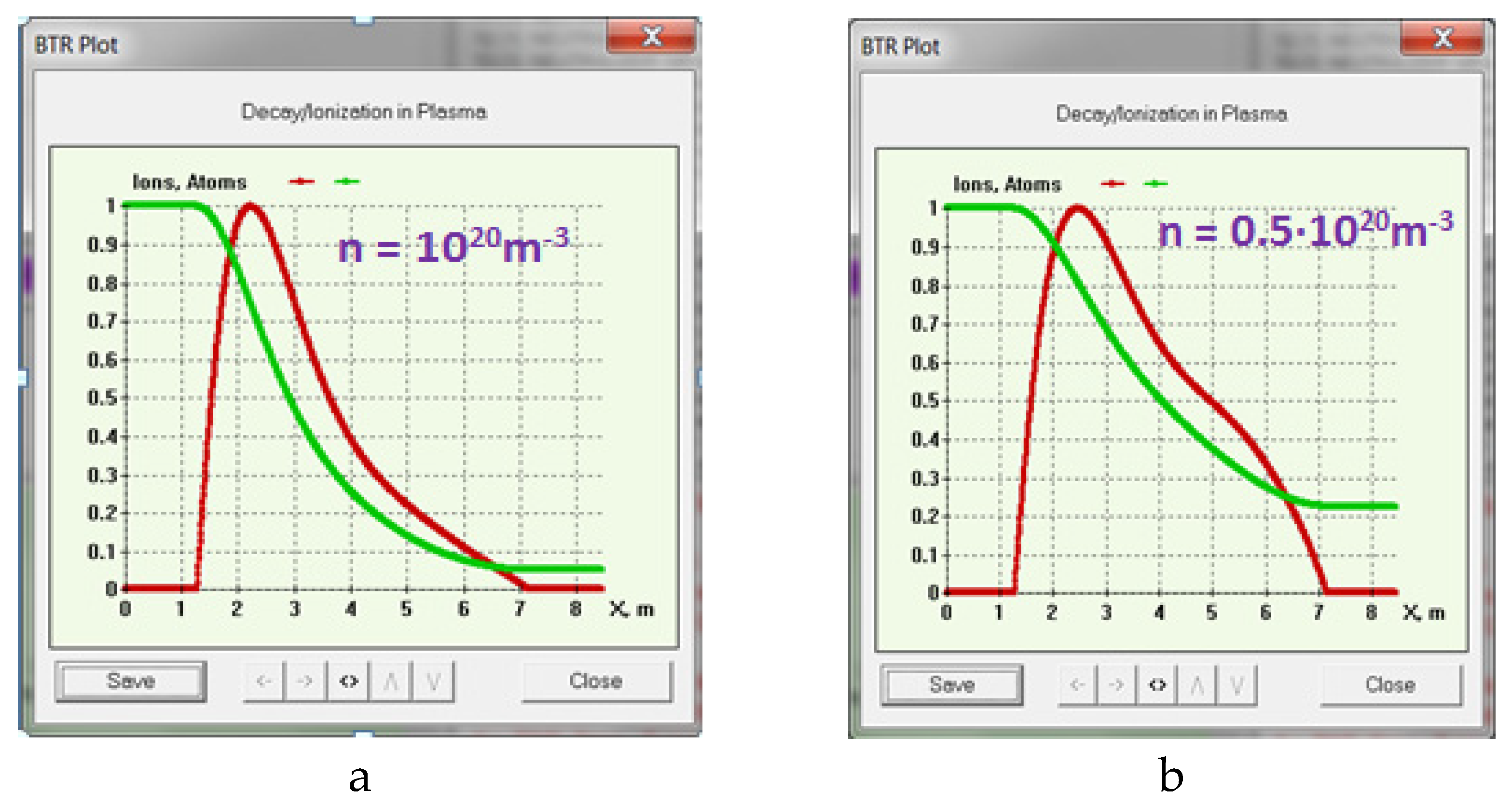
- Neutral particles ionization in plasma (tokamak volume)
- Neutral beam power/particle balance after the neutralizer
- Accelerated source beam power/particle balance without re-ionization losses
- Accelerated source beam power/particle full balance (all processes included)
- Cut-off current input parameter effect
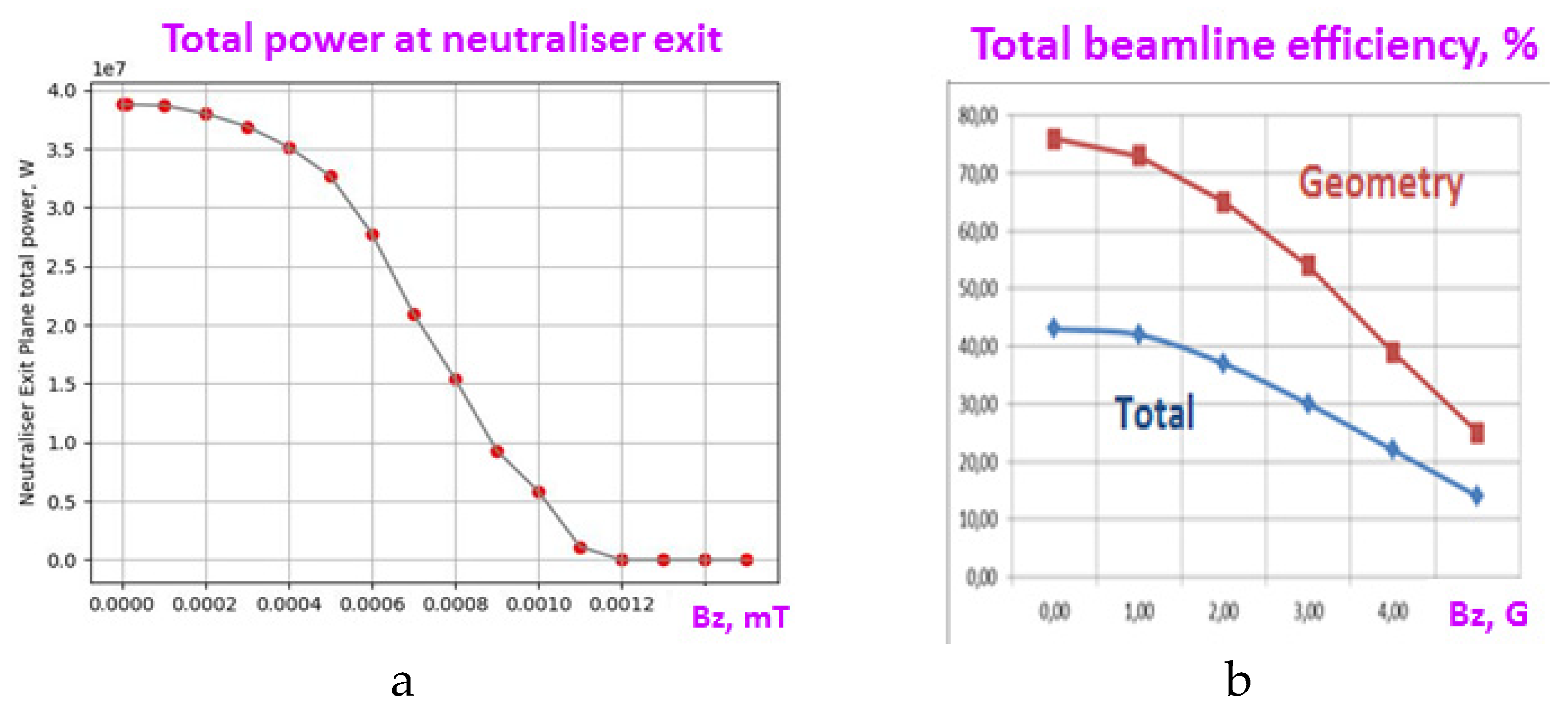
- Magnetic field magnitude effect
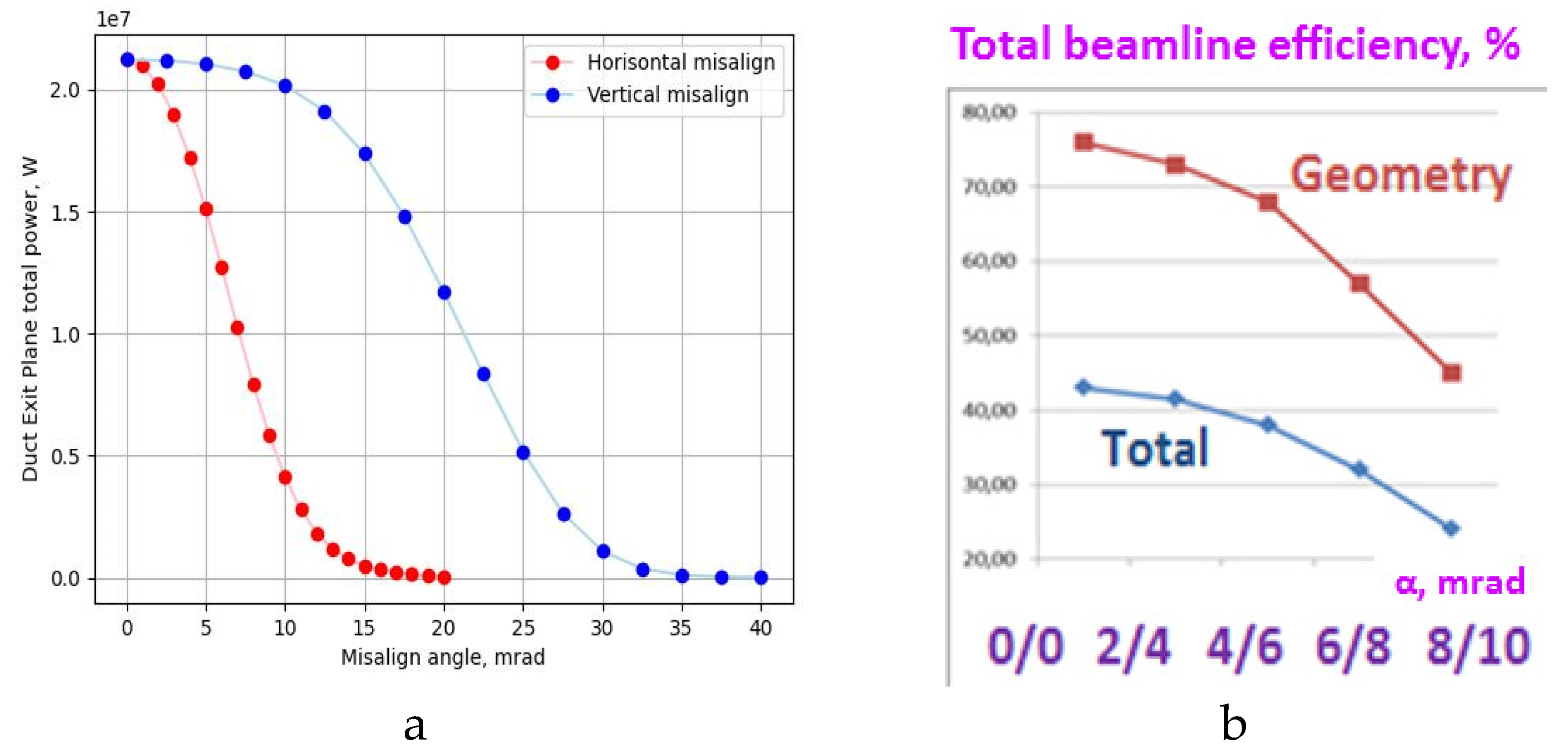
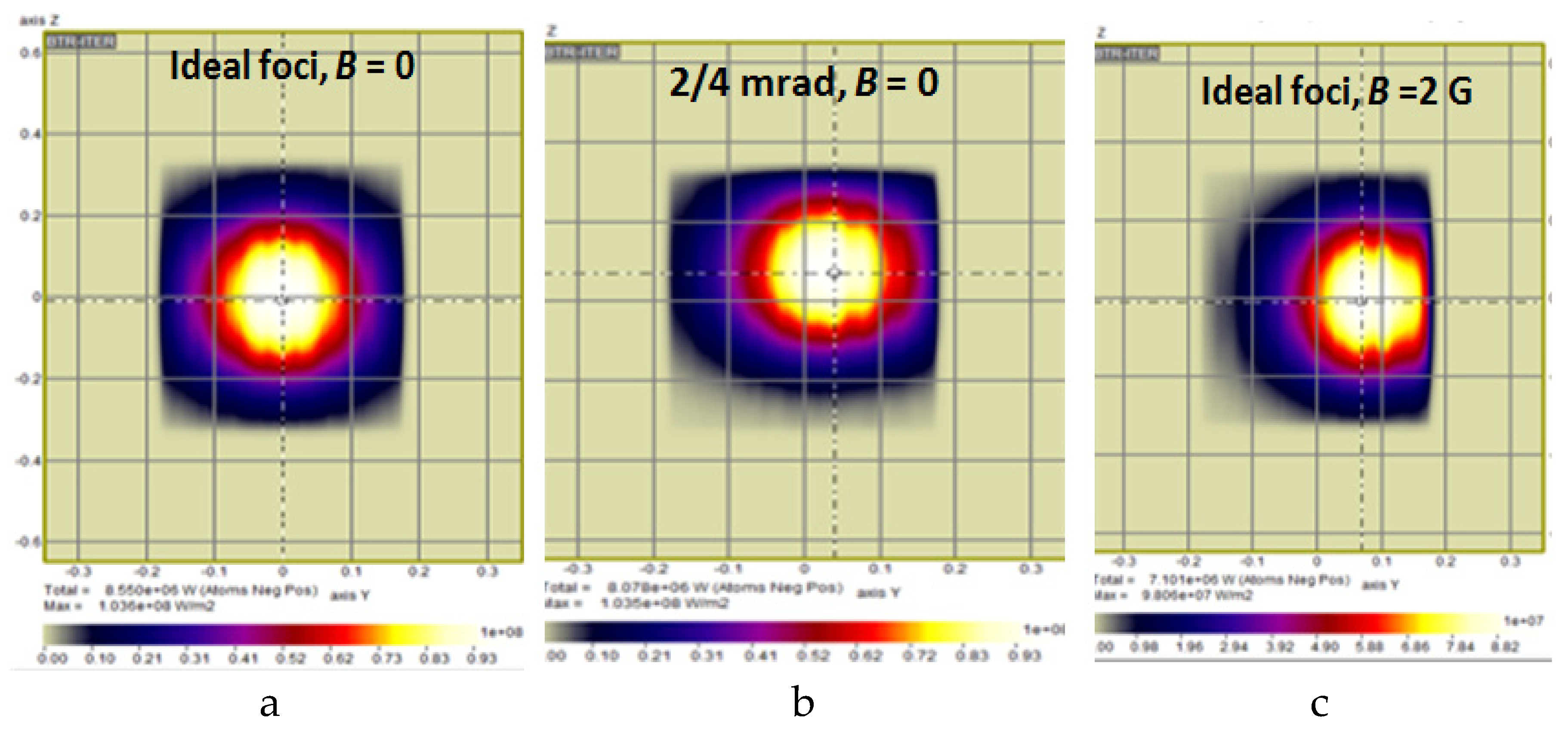
- Angular misfocusing effects
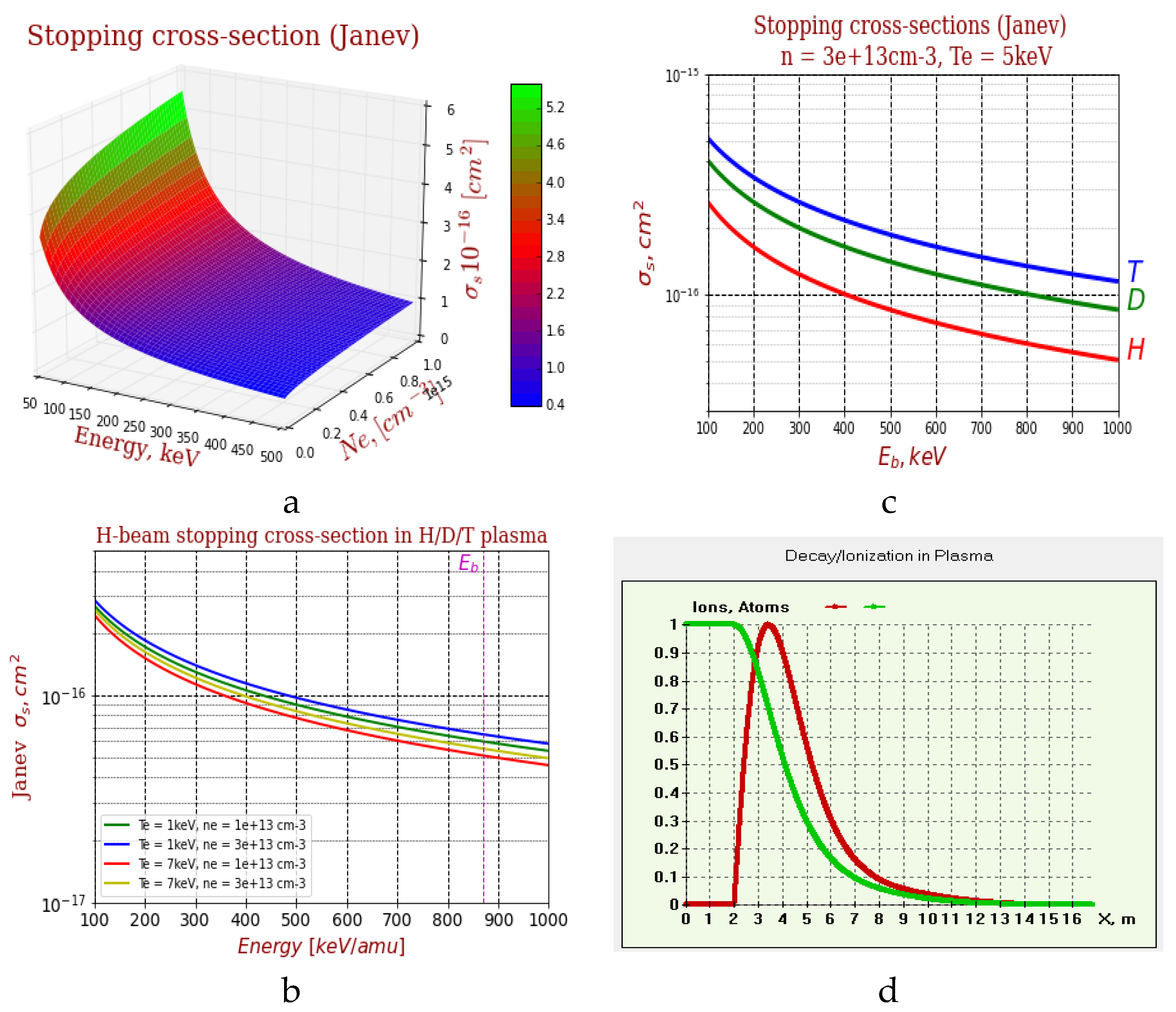
- Atomic cross-sections and target density effects
- The effects of the geometry representation accuracy, meshing and time steps, etc.
6. BTR applications
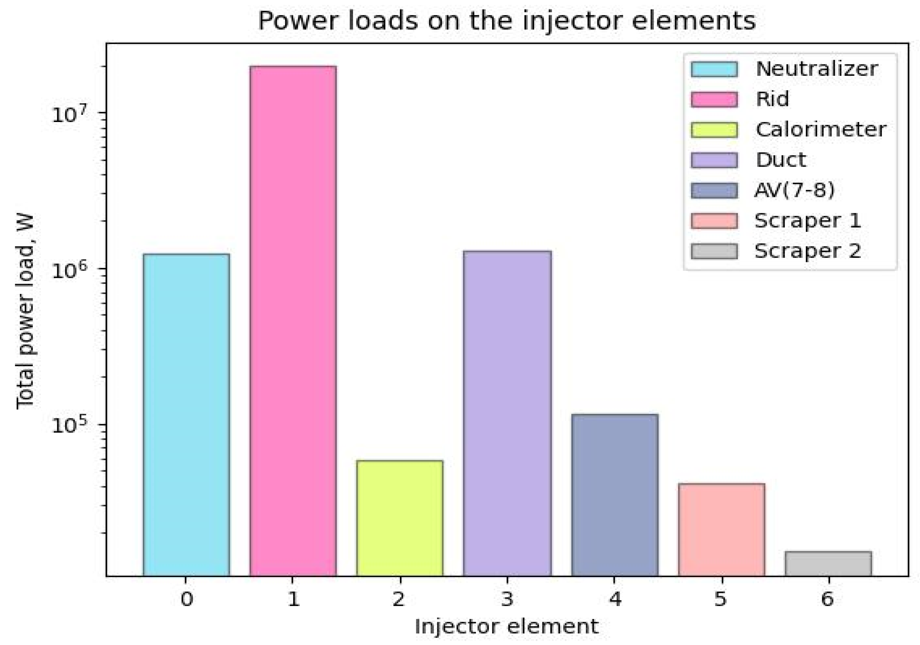
6.1. Beamline transmission and power losses
6.2. Neutral injection port optimization
6.3. Neutral beam shine-through
6.4. Benchmark of different numerical tools for NBI simulation
7. Conclusions and outlook
Acknowledgments
References
- BTR code for neutral beam design. Available online: https://sites.google.com/view/btr-code/home (accessed on 08.08.2022).
- Hemsworth R. et al. Status of the ITER heating neutral beam system. Nucl. Fusion 49 045006 2009. [CrossRef]
- ITER Final Design Report, NB H&CD, DDD 5.3, 2001, Vienna, Austria, IAEA.
- Kuteev, B.V.; Goncharov, P.R.; Sergeev, V.Y.; Khripunov, V.I. Intense fusion neutron sources. Plasma Phys. Rep. 2010, 36, 281–317. [CrossRef]
- Kuteev, B.V.; Goncharov, P.R. Fusion–Fission Hybrid Systems: Yesterday, Today, and Tomorrow. Fusion Sci. Technol. 2020, 76, 836–847. [CrossRef]
- Kuteev B.V. et al. Status of DEMO-FNS development. — Nucl. Fusion, 2017, vol. 57, № 7, p. 076039. [CrossRef]
- Hemsworth R.S. et al. Overview of the design of the ITER heating neutral beam injectors. New J. Phys., 2017, vol. 19, p. 025005. [CrossRef]
- Singh M.J. et al. Power loads on the front end components and the duct of the heating and diagnostic neutral beam lines at ITER. AIP Conf. Proc., 2015, vol. 1655(1), p. 050011. [CrossRef]
- Dlougach E.D. BTR code for NBI Design and Optimization. AIP Conf. Proc., 2021, v. 2373, p.080004. [CrossRef]
- Dlougach E.D.; Veltri P. BTR code recent modifications for multi-run operation. AIP Conf. Proc., 2021, v. 2373, p.080010. [CrossRef]
- Oh B.H., Dlougach E.D. Beam transport code for the KSTAR NB heating system, 20th IEEE/NPSS Symposium on Fusion Engineering, SOFE-03. San Diego, CA, 2003. 474-477. [CrossRef]
- M. Bandyopadhyay, M.J. Singh, C. Rotti, A.Chakraborty, R.S. Hemsworth, B. Schunke. Beamline optimization for 100-keV diagnostic neutral beam injector for ITER, IEEE transactions on plasma science, vol. 38, no. 3, 2010. [CrossRef]
- E. Surrey, A. Holmes, R. McAdams, D. King Operation of the ITER Electrostatic Residual Ion Dump with a Perturbed Field, 2010, Journal of Fusion Energy 29(5): 486-498. [CrossRef]
- Doo-Hee Chang et al., Performance of 300 s-beam extraction in the KSTAR neutral beam injector, Current Applied Physics Volume 12, Issue 4, 2012, 1217-1222. [CrossRef]
- P. Veltri, P. Agostinetti, M.D. Palma, E. Sartori, G. Serianni. Evaluation of power loads on MITICA beamline components due to direct beam interception and electron backscattering, Fusion Engineering and Design 88 (2013) 1011– 1014. [CrossRef]
- E. Sartori, P. Veltri, E.Dlougach, R. Hemsworth, G. Serianni, M. Singh Benchmark of numerical tools simulating beam propagation and secondary particles in ITER NBI, NIBS-2014 AIP Conference Proceedings 1655, 050006 (2015). [CrossRef]
- R. McAdams, Beyond ITER: Neutral beams for a demonstration fusion reactor (DEMO) Review of Scientific Instruments 85, 02B319 (2014). [CrossRef]
- E. Sartori, P. Veltri, G. Serianni, M.D. Palma, G. Chitarin, P. Sonato. Modeling of Beam Transport, Secondary Emission and Interactions With Beam-Line Components in the ITER Neutral Beam Injector, IEEE Transactions On Plasma Science, Vol. 42, No. 3, March 2014. [CrossRef]
- R. McAdams, A.J.T. Holmes, D.B. King, E. Surrey, I. Turner, J. Zacks. Negative ion research at the Culham Centre for Fusion Energy (CCFE) © EURATOM/CCFE New Journal of Physics, Volume 18, December 2016. [CrossRef]
- Mauro Dalla Palma, Roberto Pasqualotto, Emanuele Sartori, Paolo Tinti. The beamline for the ITER heating neutral beam injectors: A case study for development and procurement of high heat flux components, Fusion Engineering and Design 171 (2021) 112559. [CrossRef]
- Ananyev S.S., Dlougach E.D., Krylov A.I., Panasenkov A.A., Kuteev B.V. Modeling and optimization of the neutral beam line for plasma heating and current drive for the DEMO-FNS fusion neutron source project. Fus. Eng. and Design 161, 2020, 112064. [CrossRef]
- https://winworldpc.com/product/turbo-pascal/7x.
- Kuteev B.V. et al. Steady state operation in compact tokamaks with copper coils. Nucl. Fusion 51, 2011, 073013. [CrossRef]
- Chernyshev, F.V. et al. Study of fast-ion losses in experiments on neutral beam injection on the Globus-M spherical tokamak, Plasma Phys. Rep. Vol. 37 No. 7, 2011. [CrossRef]
- Heidbrink W.W., van Zeeland M.A. et al. Initial measurements of the DIII-D off-axis neutral beams. Nucl. Fusion, 2012, vol. 52, p. 094005. [CrossRef]
- R.S. Hemsworth, Long pulse neutral beam injection. Nucl. Fusion 43, 2003, p. 851–861. [CrossRef]
- C. Hopf, G. Starnella, N. den Harder, U. Fantz. Neutral beam injection for fusion reactors: Technological constraints versus functional requirements. Nucl. Fusion 61, 2021, 106032. [CrossRef]
- P.P. Khvostenko et al. Tokamak T-15MD—Two years before the physical start-up. Fus. Eng. and Design. Vol. 146(3), 2019, 1108-1112. [CrossRef]
- Dlougach, E.D.; Panasenkov, A.; Kuteev, B.; Serikov, A. Neutral beam coupling with plasma in a compact fusion neutron source. Appl. Sci. 2022, 12, 8404. [CrossRef]
- A.N. Karpushov et al. Upgrade of the neutral beam heating system on the TCV tokamak – second high energy neutral beam. Fus. Eng. and Design 187, 2023, 113384. [CrossRef]
- F. Jaulmes et al. Numerical modelling for beam duct heat loads calculations and application to the new 1 MW neutral beam injector in the COMPASS tokamak. Plasma Phys. Control. Fusion 64, 2022, 125001. [CrossRef]
- A.A. Ivanov, V.I. Davydenko, Yu.I. Belchenko. Negative ion and neutral beams injectors at the Budker Institute of nuclear physics. AIP Conference Proceedings 2052, 030003, 2018. [CrossRef]
- Oikawa T., Park J.M. et al. Benchmarking of neutral beam current drive codes as a basis for the integrated modeling for ITER. In: Proc. of the 22nd International Conference on Fusion Energy. Geneva, Switzerland, 2008 (Vienna, IAEA, 2008), IT/P6-5.
- Wesson J. Tokamaks, 4th Edition 2011; Oxford: Oxford University Press.
- Pankin A. et al. The tokamak Monte Carlo fast ion module NUBEAM in the National Transport Code Collaboration library. Comput. Phys. Commun., 2004, vol. 159, р. 157-184. [CrossRef]
- Janev, R.K. ; Boley, C.D.; Post, D.E. Penetration of energetic neutral beams into fusion plasmas. Nucl. Fusion, 1989, vol. 29, p. 2125. [CrossRef]
- http://btr.org.ru (old page - not available anymore!).
- Niek den Harder, Guillermo Orozco, Irene Zammuto, Christian Hopf; et al. Modeling neutral beam transport in fusion experiments: Studying the effects of reionisation and deflection. Fus. Eng. and Design, Vol 146, 2019, 518-521. [CrossRef]
Disclaimer/Publisher’s Note: The statements, opinions and data contained in all publications are solely those of the individual author(s) and contributor(s) and not of MDPI and/or the editor(s). MDPI and/or the editor(s) disclaim responsibility for any injury to people or property resulting from any ideas, methods, instructions or products referred to in the content. |
© 2023 by the authors. Licensee MDPI, Basel, Switzerland. This article is an open access article distributed under the terms and conditions of the Creative Commons Attribution (CC BY) license (http://creativecommons.org/licenses/by/4.0/).


