1. Introduction
Grey cast iron (GCI) has been extensively used in brake rotor applications due to its advantageous properties, which include outstanding castability, high thermal conductivity, good damping capability, cost-effectiveness, and adequate wear resistance. In fact, GCI is widely used as a rotor in brake systems for road vehicles. However, for this application, GCI still exhibits properties liable to be improved, like corrosion resistance, and airborne particle emissions [
1,
2].
In particular, particles generated by tribo-oxidation of GCI account for a significant fraction of particles released by braking systems[
3] and are indeed the main source of airborne magnetite (Fe
3O
4) particles in urban areas[
4,
5].
The contribution of particulate matter emissions from disc brakes to pollution and their potential for emitting toxic components are two of the most serious environmental issues today[
6]. New materials and technologies have been developed to address these concerns. For instance, carbon-ceramic composites have been established as an alternative to traditional brake disc materials since they display reduced wear rates and PM emission [
7,
8,
9], However, because of the sophisticated production methods and unique features, these kinds of discs usually come with a higher price and for specific luxury cars. The application of coatings and disc surface treatments has also been investigated to reduce wear and PM emissions of brake discs [
2,
10,
11,
12,
13,
14].
Coating GCI brake discs using direct energy deposition (DED) has proven to be an effective method, resulting in low-wear brake discs with increased durability and lower particle emission [
2,
15,
16]. As compared to reference GCI samples [
17], laser-cladded GCI brake discs with a Ni-self fluxing alloy and 60% spheroidized fused WC exhibit higher wear resistance and lower emitted particle concentrations in PoD testing. However, there is still the emission of to some extent harmful airborne particles that are released into the environment.
In this regard, the Fe
3Al, intermetallic phase exhibits promising characteristics. Fe
3Al is known for its low environmental impact, as it is composed of abundant and non-toxic elements. Unlike certain coatings containing hazardous elements like W, Ni, and Co [
18,
19,
20], Fe
3Al eliminates the concerns associated with the release of harmful airborne particles. Additionally, Fe
3Al exhibits good corrosion resistance, making it an attractive choice for coating applications, for those applications requiring surface durability. These favorable qualities, combined with its relatively low cost and availability, place Fe
3Al as a desirable alternative to stainless steel and other materials in various industrial sectors [
21,
22]. Recently, the possibility of manufacturing Fe
3Al coatings on materials with lower corrosion resistance, such as low alloy steel, has been investigated [
23]. Comparing the wear resistance of iron aluminide alloys to that of other ceramics and metals, Alman et al. [
24] research indicated that the resistance of iron aluminides was comparable to that of stainless steels.
Numerous studies have primarily focused on the application of the coating for improving the wear resistance of brake discs [
13,
14,
17,
25], frequently neglecting the critical environmental considerations associated with the selection of coating materials. Considering the promising characteristics of Fe
3Al and its potential as a coating material, this study aims to investigate the microstructure and wear resistance of Fe
3Al coating on GCI prepared via DED. Using Fe
3Al powder, we intend to minimize the release of toxic elements into the environment, within the more general task of developing environmentally friendly brake systems with enhanced performance and reduced environmental impact.
2. Materials and Methods
A gas-atomized, spherical Fe
3Al powder with a D50 of approximately 90μm was used as the initial raw material, which was supplied by NANOVAl company. In
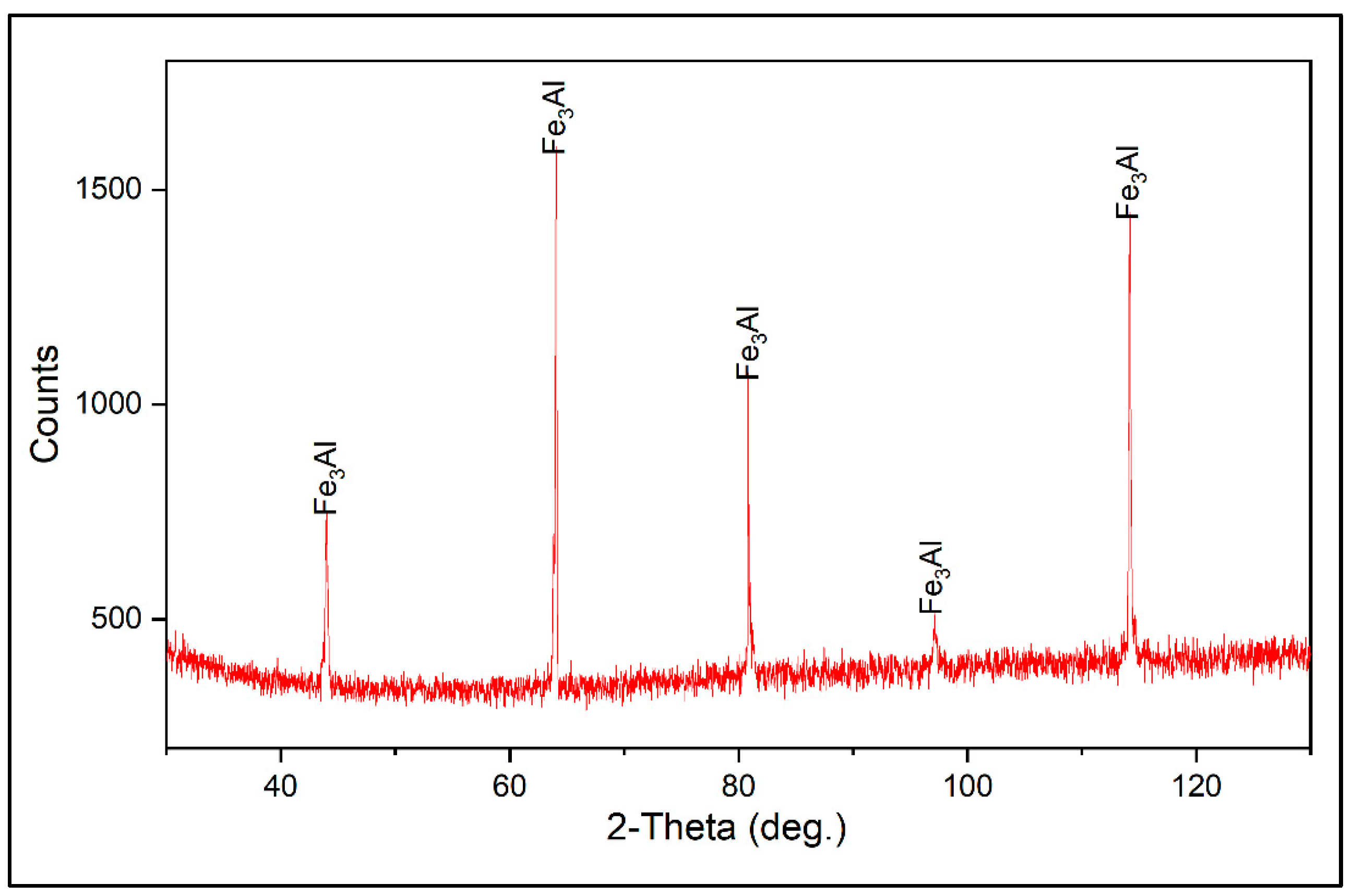
Figure 1, the scanning electron microscope (SEM) micrographs of the powder and optical microscope (OM) cross-section view of the coating is shown. Based on the X-ray diffraction (XRD) analysis conducted on the initial powder (see
Figure 2), the only phase detected was Fe
3Al. This is supported by energy dispersive X-ray spectroscopy (EDXS) investigations, which indicated that the composition of the powder lies inside the Fe
3Al phase range (Fe-13.5wt.%Al). A buffer layer of Cr-Mo steel coating material was considered for improving the coating quality and adhesion. The composition of the buffer layer material is given in
Table 1.
For the deposition of the Fe
3Al coating, it is necessary to pre-heat the GCI substrate at temperatures higher than 150˚C in order to prevent defects and cracks generation in the coating structure. The deposition of a buffer layer prior to the deposition of the iron aluminide coating can provide enough energy for pre-heating the substrate, also improving the bonding of the coating to the substrate. A buffer layer of Ferro 55 composition was deposited on the GCI disc right before the deposition of Fe
3Al coating (
Table 2). After the buffer layer, the Fe
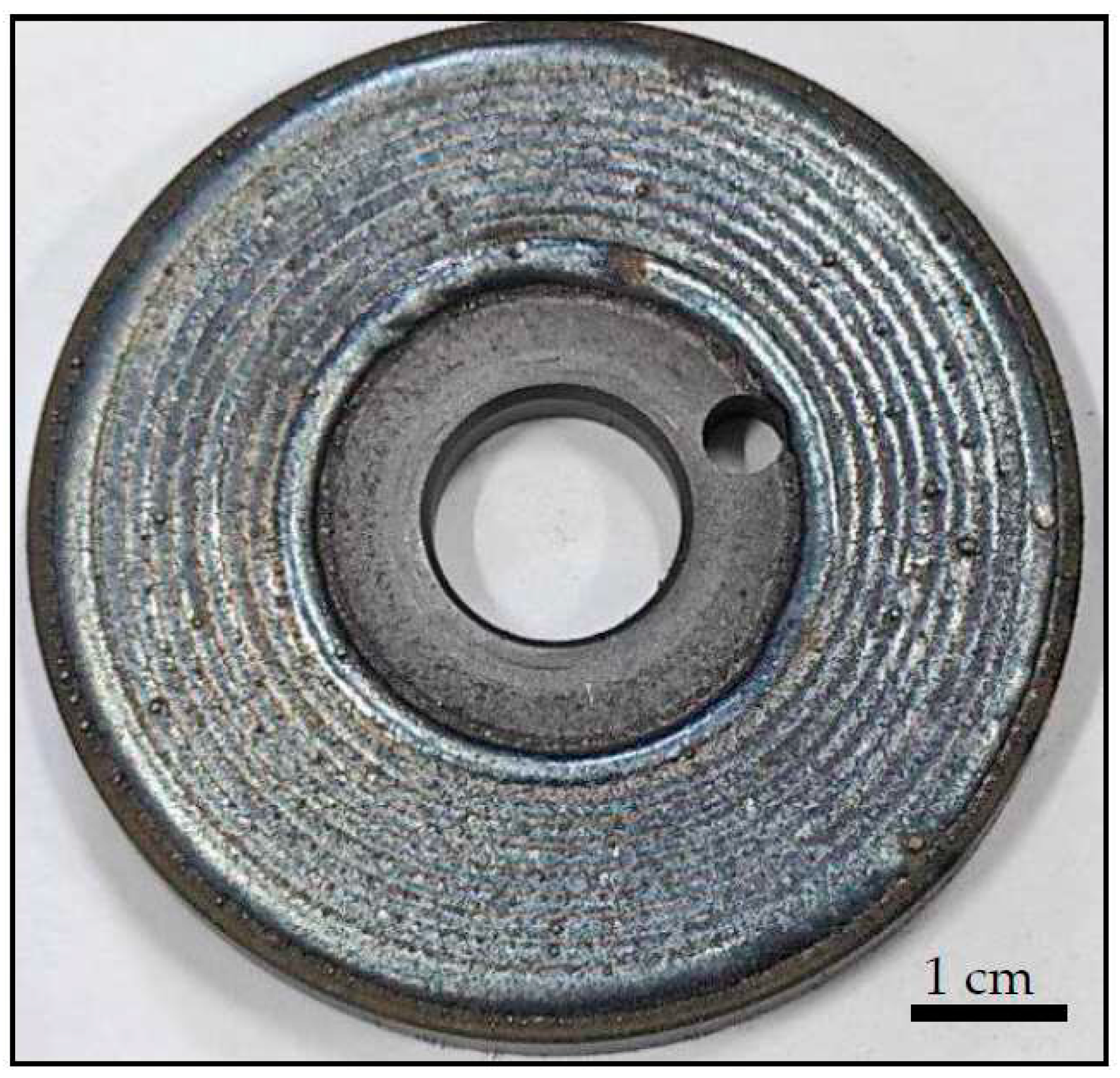
3Al coating was deposited at a scanning speed of 1000mm/min, with a power of 1000W, and a powder feeding rate of 11 gr/min (
Figure 3).
To assess the coating's tribological characteristics and to get insight into the fundamental behavior of the coating sliding against brake pad friction materials a dry sliding pin-on-disc (PoD) test was performed. Two friction materials with different compositions were used to investigate the tribological behavior of the coating system. Cu-free and ECOPADS [
26] friction materials were chosen as the pin materials, and their compositions, as indicated by EDXS analysis, are given in
Table 2. For the PoD test, 14400 m of total sliding distance, 2 m/s of sliding speed, and 0.6 MPa of applied pressure were considered. The selected PoD test conditions were intended to approximately simulate the mild wear condition, which is typical for braking systems [
1,
10,
11,
15]. The PoD test was also carried out on a GCI disc under identical testing conditions in order to provide a better reference point and an understanding of the coating properties comparatively. To avoid the initial surface roughness contributing to the final wear results, the same surface initial roughness Ra was taken into consideration for all samples (approximately 0.25 μm).
Dry sliding wear tests were conducted using a Biceri PoD tribometer at room temperature, following the ASTM G99 standard. Three trials were conducted for each combination of disc and friction material. The assessment of wear resistance was pursued through the measurement of weight loss using a scale with an accuracy of ±0.1mg. The height deviations of the pins were measured with a digital caliper, and subsequently, these data were used to calculate the wear rate.
Specific wear rate (Ka) was considered to compare how the different friction materials behaved when they were slid against each other. The following formula (Eq. 1) is used to calculate Ka:
Where ΔV(m3) is the wear volume measured after the wear test, Fn (N) is the applied load, and S (m) is the sliding distance.
The wear volume of the pin was estimated through the division of its weight reduction by its apparent density. To determine the wear area of individual discs, three measurements were conducted along the radial direction of the wear track using a profilometer instrument (model Hommel Tester T1000, featuring a tip with a curvature radius of 5 µm). The scanning length on the disc was 12 mm with a scanning speed of 0.15 mm/s. The average wear volume of the discs was calculated as Eq. 2:
Where r is the average wear radius, and A is the calculated wear area.
An Optical Particle Sizer (OPS) (TSI Incorporated, Shoreview, USA) was used to measure the size of the emitted particles. With a sampling rate of 1Hz, the OPS instrument counts particles between 0.3 m and 10 m in size. As for the PM concentration, the OPS device can sample between 0 and 3000 particles/cm3.
A LASERTEC653D hybrid machine (DMGMORIAG, Germany) with a 2500W diode laser (=1020nm) and a Coax14 powder nozzle was used to make for the deposition of the coatings. The laser had a focal length of 13 mm and a pot diameter of 3 mm with a top hat beam profile. The beam profile was shaped like a top hat.
The cladded layers underwent etching using a Nital solution with a concentration of 2%. The study involved the use of a JEOL IT 300 SEM with an EDXS system for semi-quantitative composition analyses to conduct microstructural observations of the coating and the worn surfaces of the pins and discs. The SEM was operated at an accelerating voltage of 20 kV.
The coated disc underwent XRD analyses in order to assess its phase composition. Data were collected with an Italstructures IPD3000 diffractometer, which employed a Co Ka radiation source and an Inel CPS120 detector. The detector was able to simultaneously capture the signal over an angular span ranging from 5° to 120°.
The microhardness of the coatings was measured using a Future-Tech microhardness tester (FM-310) on a polished cross-sectional sample. The assessment was conducted from the surface down to the GCI substrate, with a force load of 300 grams and a 10-second indentation duration. The study on hardness was conducted in a sequential manner, commencing from the surface layer and progressing downwards, with a series of indentations spaced at regular intervals of 0.15 mm. The objective was to gain a comprehensive understanding of the variations in hardness across the various layers.
3. Results
3.1. Coating characterization
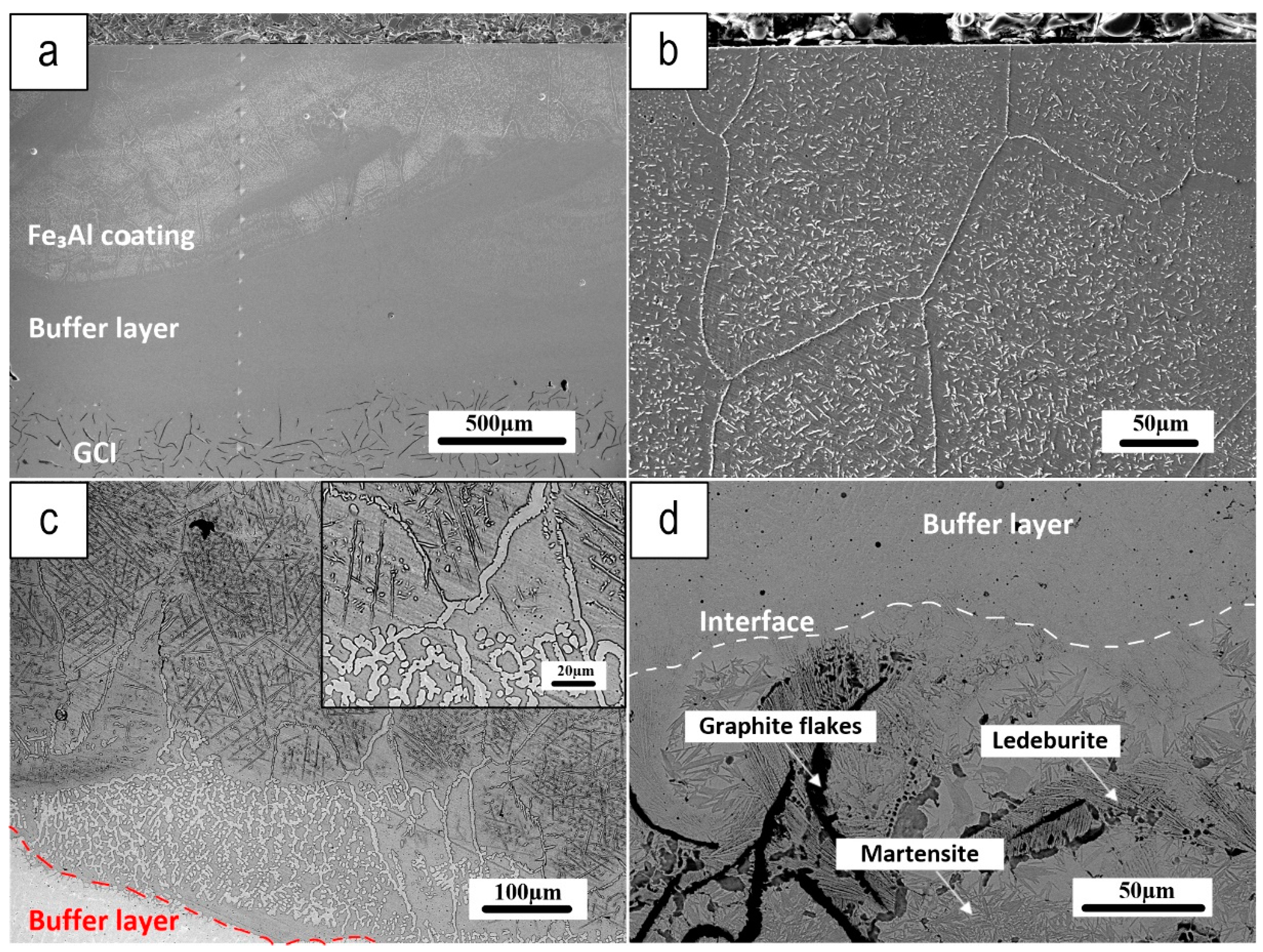
Figure 4 depicts a cross-section of the Fe
3Al coating (Fe
3Al coating with Ferro 55 Buffer layer), where a buffer layer of F55 was first deposited onto the GCI before the deposition of the Fe
3Al coating. The buffer layer was intended to improve coating quality by decreasing defects deriving from the interaction of the Fe
3Al coating with the GCI substrate during deposition and solidification.
Figure 4a shows a low-magnification view of the coating cross-section from the top to the bottom, which shows a defect-free coating microstructure, particularly at the substrate/buffer layer boundary. Micrographs of the Fe
3Al coating (shown in
Figure 4b) demonstrate that it is composed of large grains with small needles scattered throughout, which referring to the EDXS maps (
Figure 5) the needle-like grains seem to be the Fe-Al carbides.
Figure 4c depicts the interface between the top coating and the buffer layer, revealing a significant diffusion of the buffer layer into the Fe
3Al coating, mainly along the grain boundaries. Outer parts of the coating are affected by diffusion from the substrate to a lower extent, showing smaller and less numerous needle-like grains.
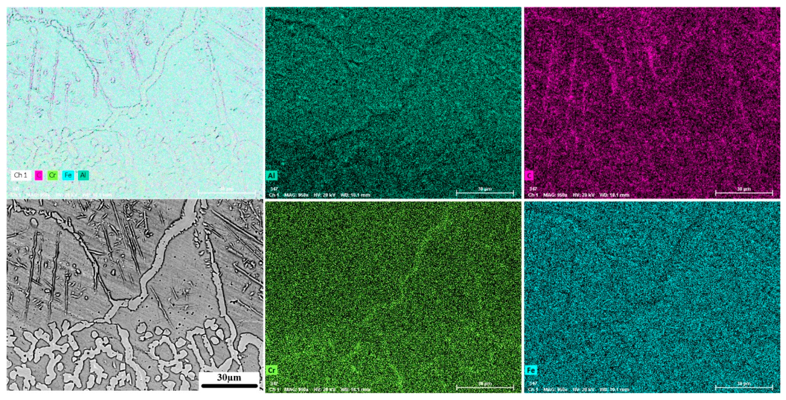
Figure 5 shows X-ray element distribution maps acquired at the boundary region between the buffer layer and the Fe
3Al coating (magnified area in
Figure 4c). It reveals that the Fe
3Al coating contains large carbon-enriched needle-like grains. These grains are Fe-Al carbides resulting from the diffusion of carbon from the buffer layer. Interestingly, the grain boundary of the coating has a higher concentration of chromium confirming that the main pathway for the diffusion of carbon is the grain boundary region.
Figure 4d shows a high-resolution micrograph of the GCI microstructure near the interface with the buffer layer. The laser beam melts the F55 powder during deposition, with the residual heat partially melting the GCI, thus promoting the diffusion of carbon from the graphite flakes in the GCI. As the melt pool passes away, rapid solidification of the GCI near the deposition boundary produces a martensitic structure. On the edge of the graphite flakes, there are also chilled ledeburite phases.
Grum and Sturm [
27], observed the development of ledeburite shells around graphite in cast iron during laser surface remelting. They propose that the carbon-saturated iron, surrounding the graphite flakes, solidifies near the eutectic point. Because the higher temperatures in the HAZ are near the border, carbon diffusion promotes the formation of broad regions of ledeburite along the coating-substrate interface.
Figure 4d shows a very good metallurgical bonding between the GCI and the buffer layer, and the presence of a martensitic structure in the HAZ.
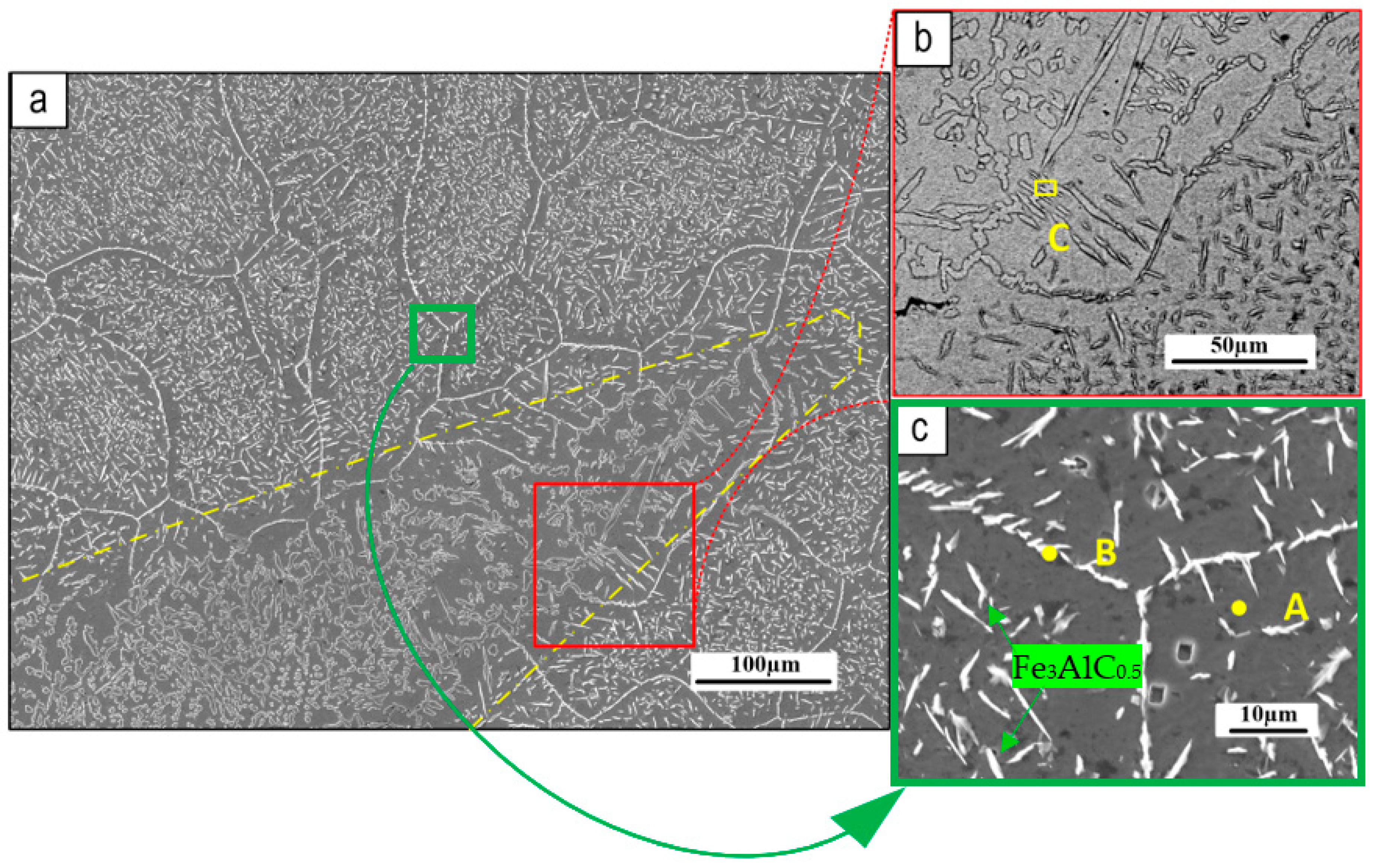
Figure 6 shows SEM images of the coating microstructure. Needle-like particles can be seen dispersed throughout the coating matrix.
Figure 6a depicts a mixed area, the edge of which is outlined by a yellow dashed line, where buffer layer components diffused outward into the surface Fe
3Al coating, altering its typical microstructure.
Figure 6b shows a higher magnification view of this mixed area, close to the interface with Fe
3Al coating indicating the difference between the grain size in this mixed area and the usual Fe
3Al microstructure (shown in high magnification in
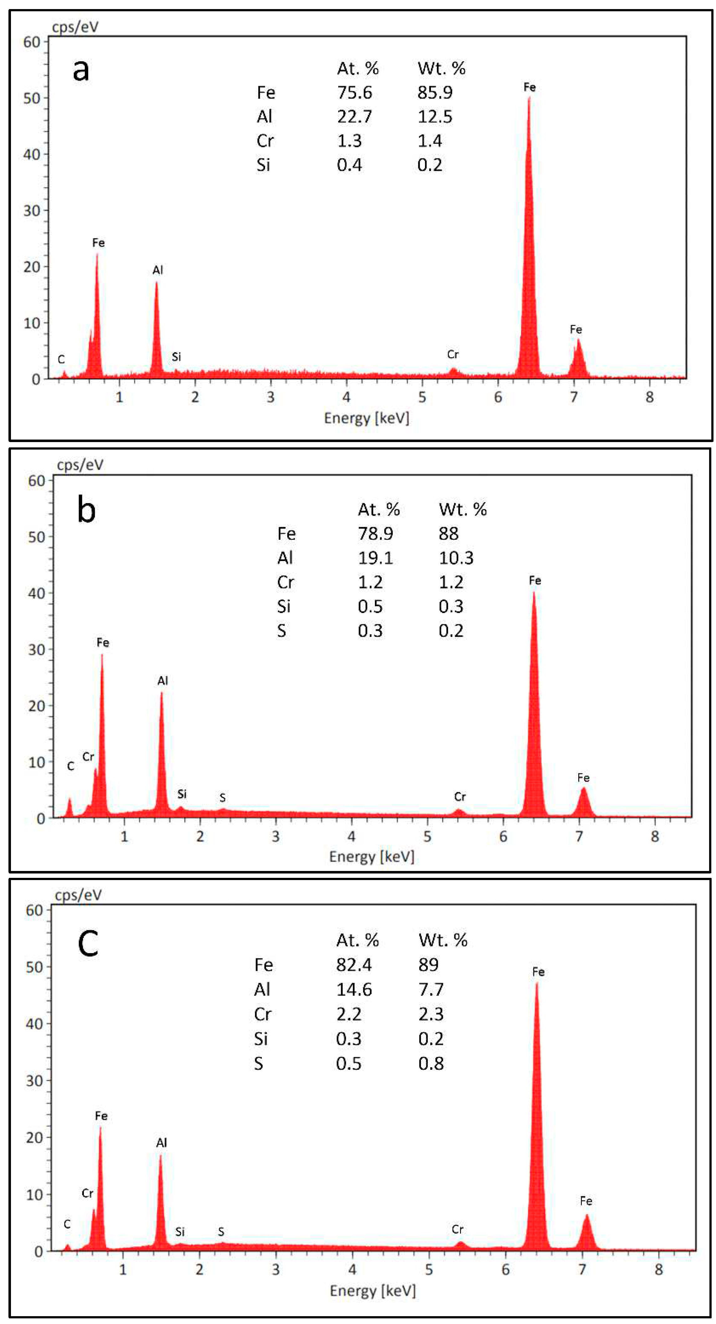
Figure 6c). This picture is confirmed by the analytical data. Figures 7a and 7b show the EDXS results obtained from the pointed areas on the coating matrix and the needles, respectively (
Figure 6), revealing that elements from the buffer layer, such as Cr, C, and Si, have dissolved into the Fe
3Al coating. Furthermore, by comparing the intensity of the carbon in the matrix and needles (
Figure 7a and
Figure 7b), it can be seen that the concentration of carbon in the needles is greater than that in the matrix (as was clearly shown in
Figure 5 for the cross-section of this coating). The EDX spectrum in Fig 7c, referring to the mixed area (point C in
Figure 6b), reveals the presence of a relatively higher quantity of Fe and Cr and a smaller amount of Al in the mixed area. These findings indicate a significant diffusion from the buffer layer, mainly along grain boundaries toward the coating surface.
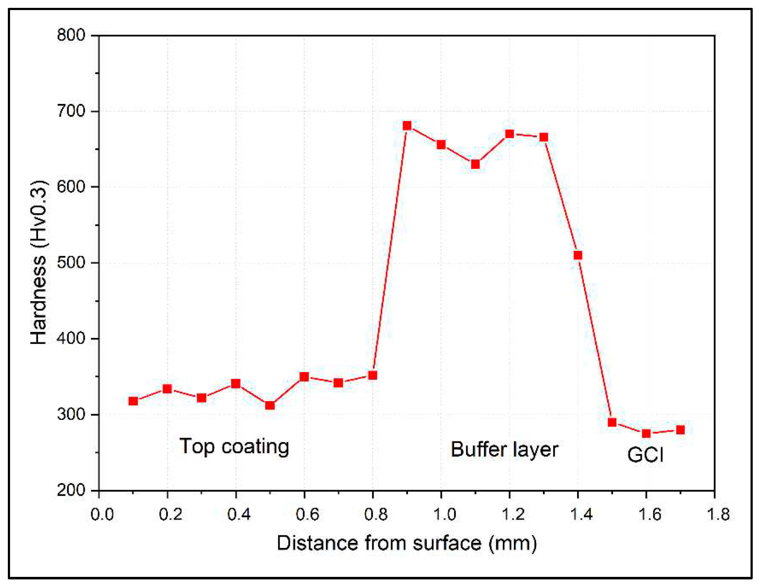
Figure 8 shows the Vickers hardness profile of the Fe
3Al coating. This profile was collected at the center of the sample, away from the edges (i.e., the first and last deposition tracks). The hardness of the Fe
3Al coating is between 310 and 350 HV0.3. However, it rises sharply in the F55 buffer layer to roughly 650-690 HV0.3, a typical hardness value for the F55 coating. The hardness of the HAZ is also in this range, after passing it through the GCI substrate, the hardness drops below 300HV0.3.
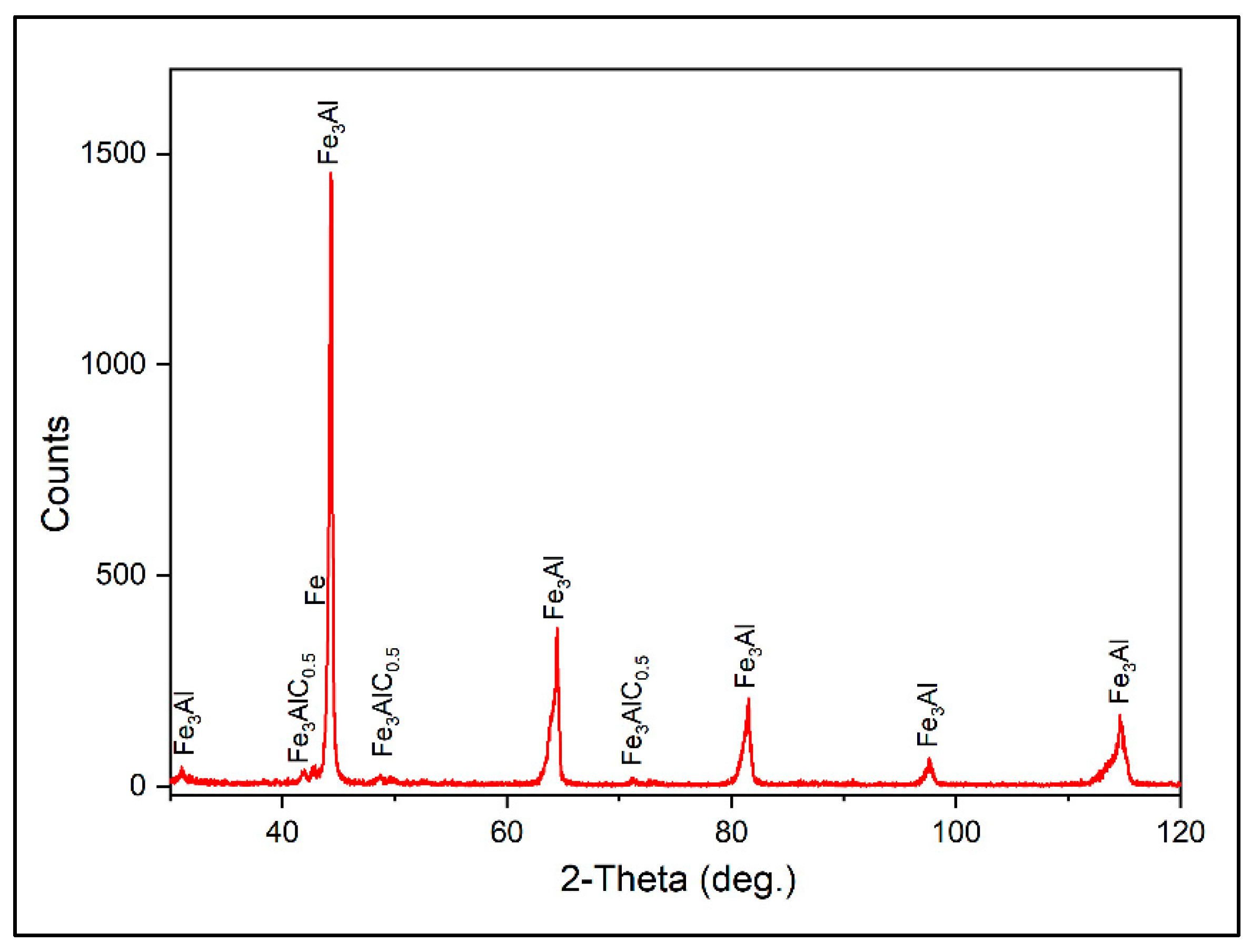
The existing phases in the Fe
3Al coating were also identified with XRD analysis (
Figure 9). The main detected phases are Fe
3Al, Fe
3AlC
0.5, and Fe. According to the XRD results, the formation of the Fe
3AlC
0.5 phase is a further consequence of the reaction of the matrix with the diffused and dissolved carbon from the bottom layer.
3.2. Wear test results:
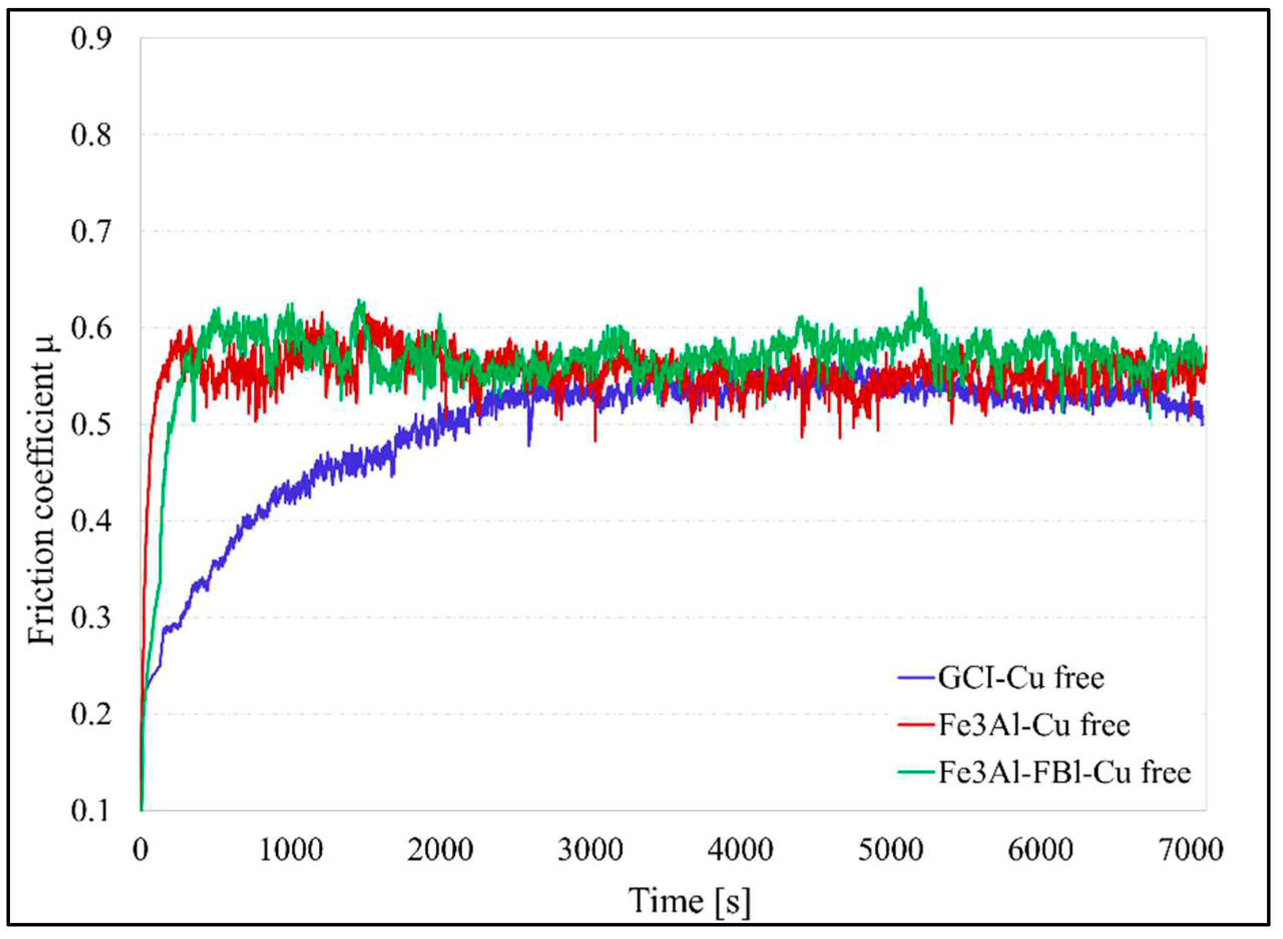
Figure 10 shows the trends in friction coefficient for the Fe
3Al coated disc, as well as uncoated GCI without coating as a control sample to be compared with coating The GCI/Cu free couple takes a longer time to reach a steady state friction coefficient (about 3000s), whereas the coupling involving the coated disc takes a relatively short period. The friction coefficient for the GCI/Cu-free and Fe
3Al/ECOPADS sliding couples are approximately the same at steady state (0.54). The friction coefficient for the Fe
3Al/Cu-free sliding couple reaches around 0.57.
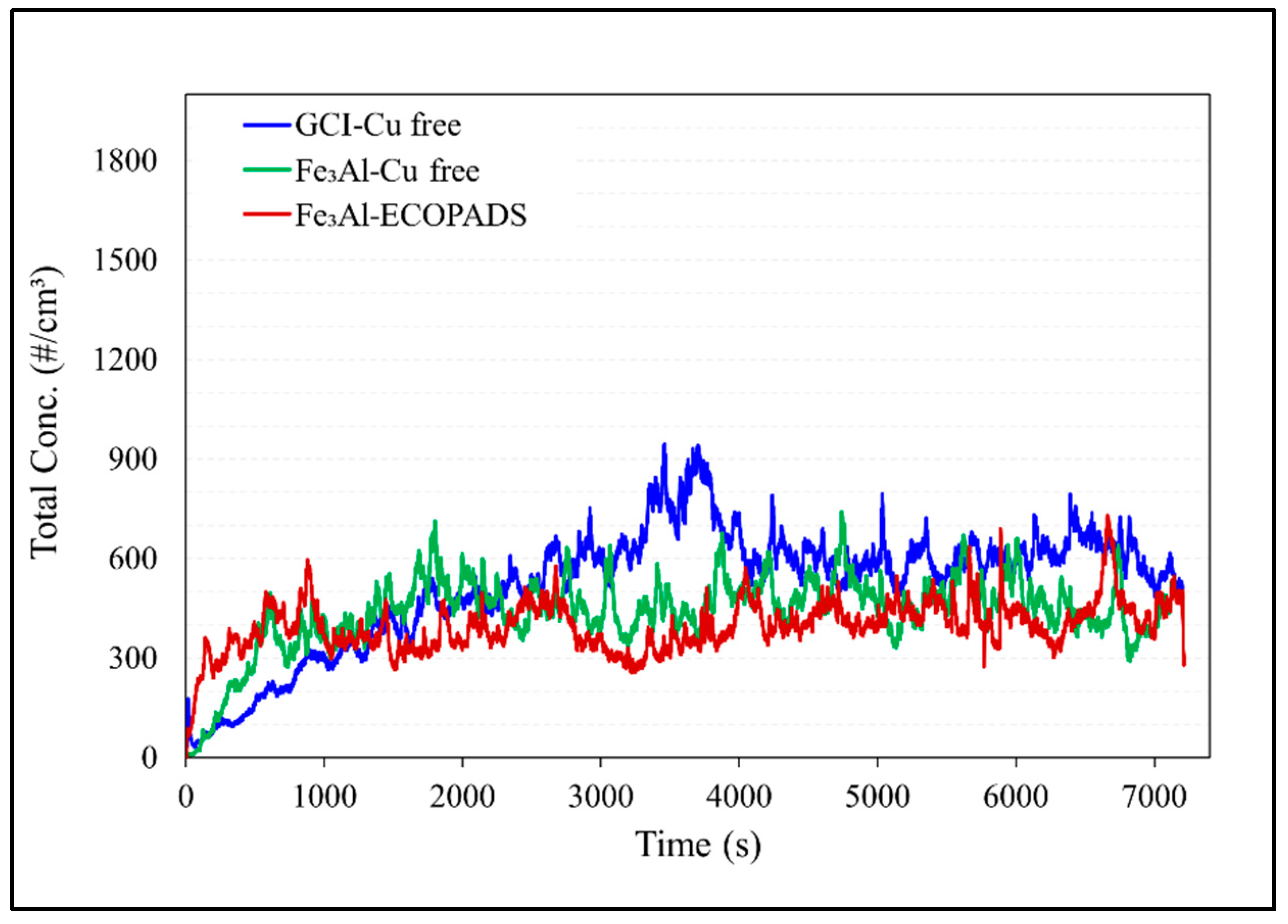
Figure 11 shows the corresponding particulate matter emissions during a pin-on-disc test. The emissions have the same growing tendency as the COF in the case of the uncoated disc, i.e., increasing with increasing COF during the running-in period before reaching a steady state. Comparing the emissions of different sliding couples, the Fe
3Al /Cu-free couple has considerably lower emissions (476#/cm
3) than the GCI/Cu-free couple (600#/cm
3). The Fe
3Al /ECOPADS sliding couple, which takes into account the wear dependency in the composition of the friction material, has even lower emissions (411#/cm
3) than the Fe
3Al/Cu-free couple.
As stated before, the tribological properties of the Fe
3Al coating were investigated as concerns about its wear behavior when sliding against two different friction materials: Cu-free and ECOPADS. The results are presented in
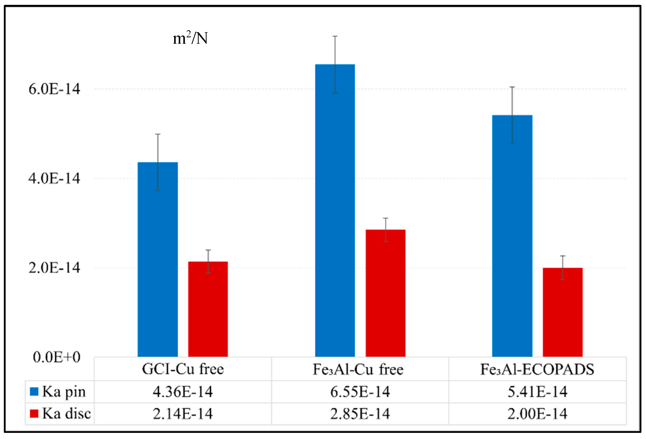
Figure 12, which shows the wear of the pin and counterpart disc under diverse sliding circumstances for all samples. A comparison of the wear behavior of the coating against Cu-free and ECOPADS friction materials showed that the Fe
3Al/ECOPADS couple has a lower total Ka value than the Cu-free/coating sliding couple, indicating better wear resistance of the former. When the coated disc slides against the ECOPADS friction material, the Ka value of the Fe
3Al disc was 2.00×10⁻¹⁴ m
2/N, which was slightly lower than when sliding against Cu-free friction material (2.85×10⁻¹⁴ m
2/N). On the other hand, when sliding against Cu-free friction materials, the Ka value of GCI was 2.14×10⁻¹⁴ m
2/N, which increased to 2.85×10⁻¹⁴ m
2/N when the GCI was replaced with a coated disc (i.e., Fe
3Al/Cu-free sliding pair). Further analysis of the worn surface of the pin and disc will provide insight into the active mechanisms that caused the observed difference in wear behavior between the coating against the two different friction materials.
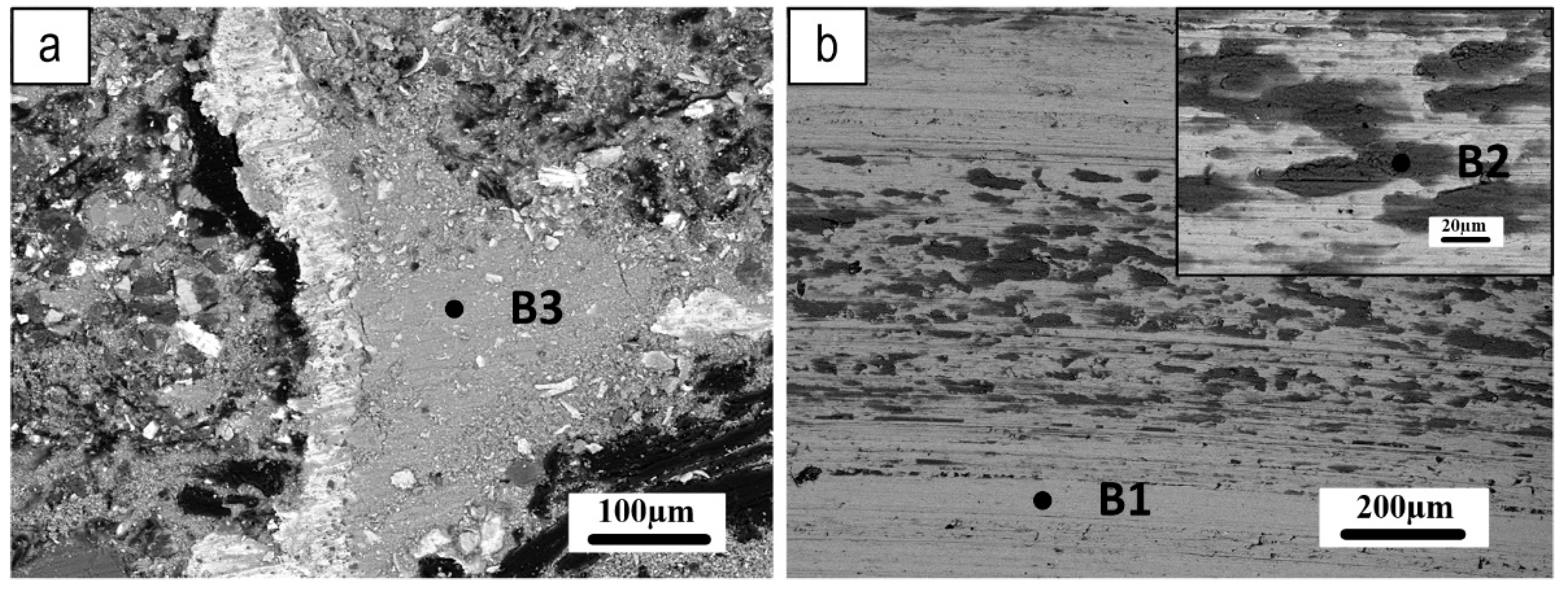
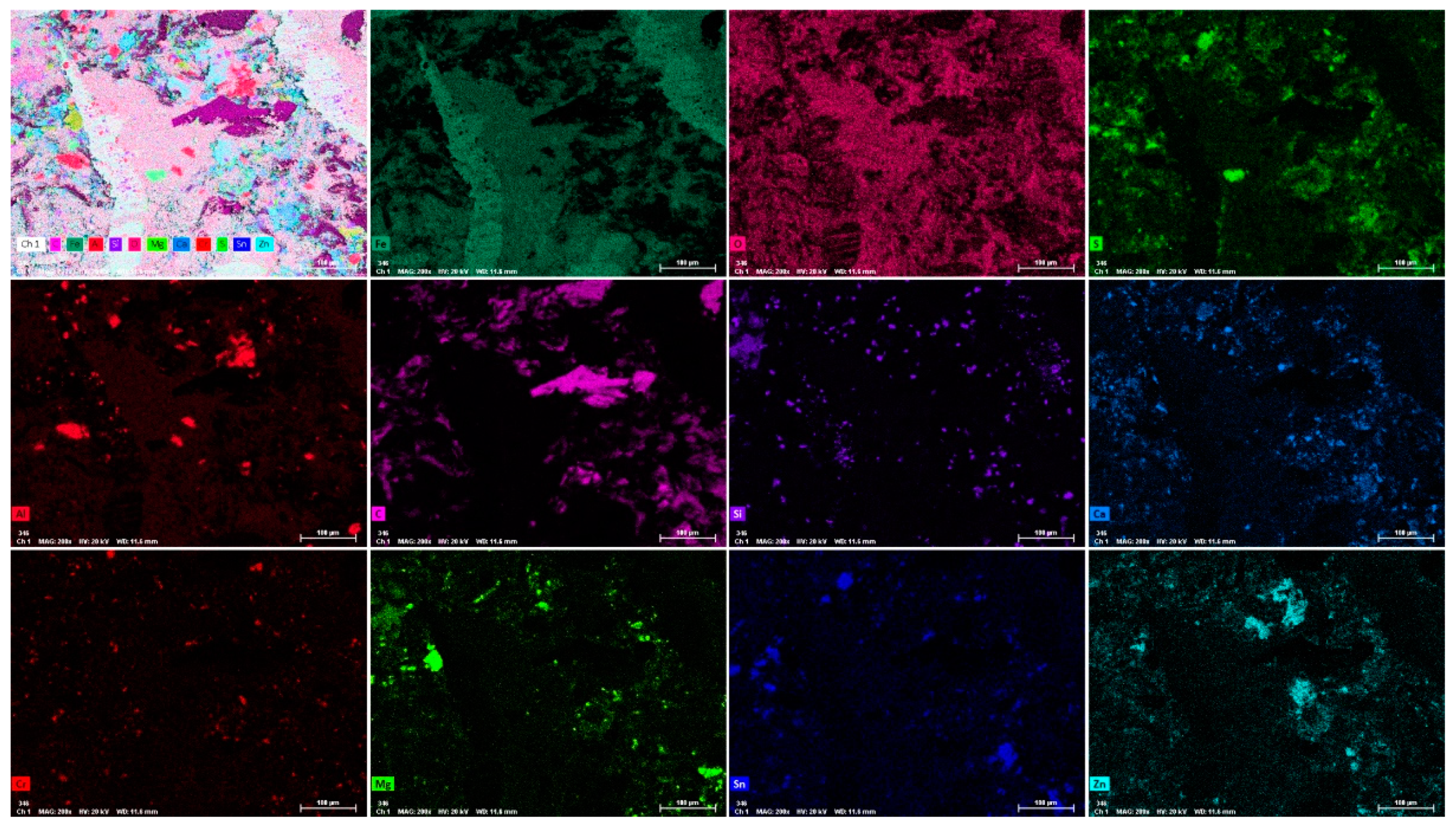
Figure 13 shows the typical morphologies of the worn surfaces of the pin and related counterpart discs. In this figure, a compacted secondary plateau can be seen forming aside the iron fibers, acting as primary plateaus, once emerging from the worn pin surface, thus blocking and favoring the compaction of the wear debris. The X-ray maps in
Figure 14 show the spatial distribution of the main elements on the worn pin surface, providing interesting clues on the contribution of oxides to the formation and extension of secondary plateaus on the surface of the pin.
Figure 13b shows wear tracks on the Fe
3Al-coated disc at two different magnifications. Many grooves can be seen along the sliding direction, indicating the occurrence of abrasion to some extent in the disc wear. These surface features are typically produced by abrasive phases with higher hardness, such as MgO, Al
2O
3, and other oxides, which contribute to the wear during the PoD test. Additionally, darker gray color patches can be seen on the wear tracks, where most of the transferred material is located.
Table 3 shows the results of the EDXS investigations of three different spots, as indicated in
Figure 13, selected as follows a point of the wear track where there is no sign of transferred materials (B1); patches of transfer layer on the wear track on the disc (B2); secondary plateau on the worn pin surface (B3). The EDXS analysis confirmed the presence of all the elements from the friction material and a relatively large amount of Fe and Al originating from the Fe
3Al coating.
The analyses for the Fe3Al/Cu-free mating couple indicate a high content of iron oxides in the secondary plateaus on the pin surface and transfer layer on the disc. Iron turned out to be always in association with a relatively large amount of Al, originating from the coating.
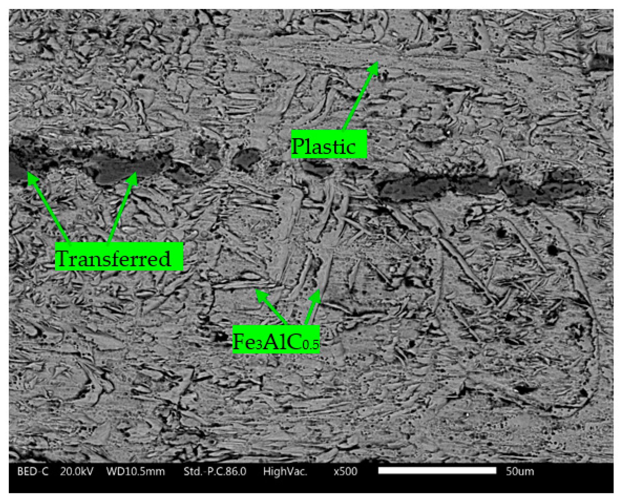
Figure 15 depicts the etched surface of the coating after the PoD test against the Cu-free friction material. It was observed that there were materials transferred from the pad and coating onto the wear track. The Fe
3AlC
0.5 carbide phase (
Figure 5 and
Figure 9) was also observed on the etched surface. The microstructure of the coating indicates that plastic deformation occurred at the surface due to sliding contact with friction materials during the PoD test.
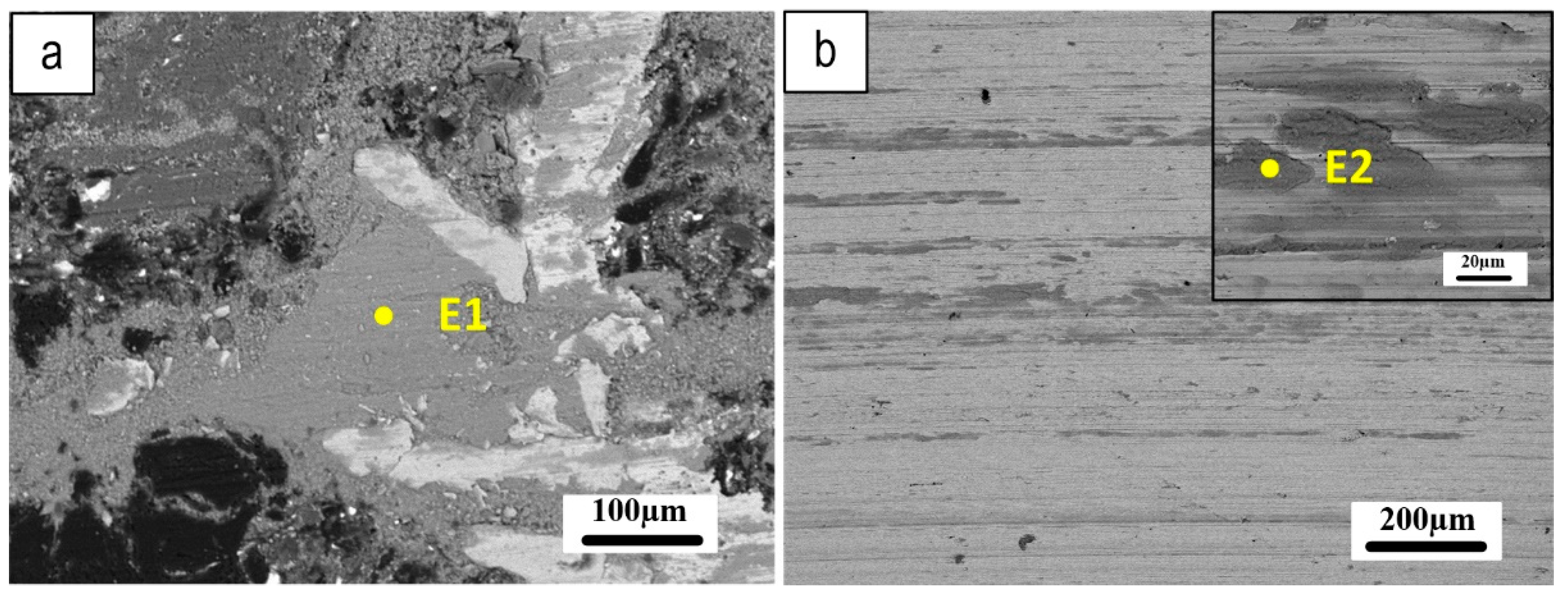
Figure 16 shows SEM micrographs of the worn pin and wear tracks on its counterpart Fe
3Al disc, offering important insights into the tribological behavior of the system. The well-compacted secondary plateaus observed on the worn pin surface (
Figure 16a) suggest that the tribo-oxidation mechanism played a role in the wear process. Meanwhile, the parallel scratches and small amount of transferred material observed on the coated disc (
Figure 16b) indicate that the abrasion mechanism may have been a significant contributor to wear.
Table 4 provides EDXS analysis of the friction layer on the pin and coated disc, corresponding to the coded points in
Figure 16 (E1 and E2). The elemental compositions reveal contributions from both the pins and coating materials, providing further insight into the underlying mechanisms of the tribological behavior of the system.
The particles that are released into the PoD chamber can offer valuable insights into the mechanisms of formation and disruption of the friction layer.
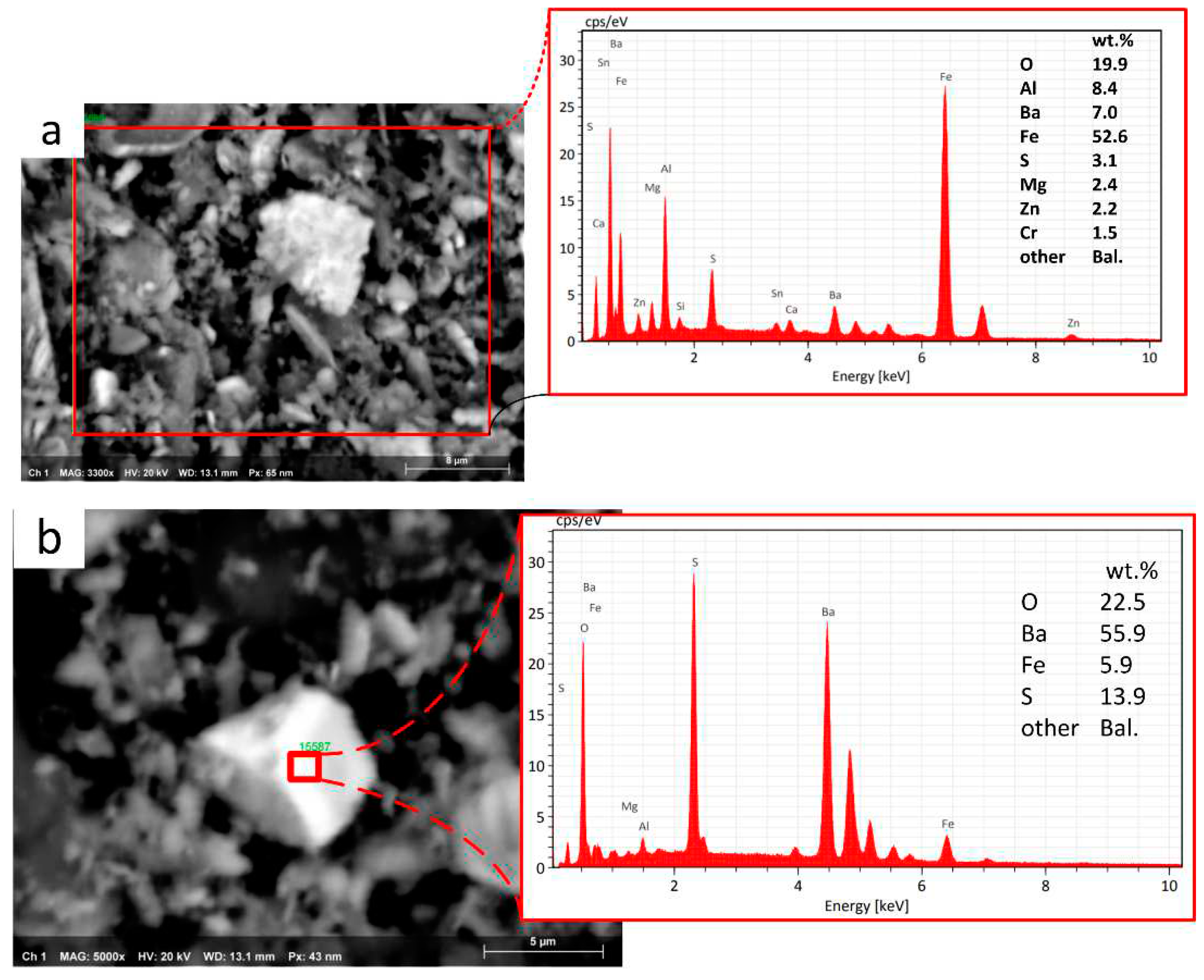
Figure 17 presents the EDXS semiquantitative chemical analysis of the particles emitted from the Fe
3Al coating/ECOPADS sliding couple and picked up from the inner walls of the PoD enclosure. A full-frame EDXS analysis of the particles (
Figure 17a) indicates that their chemical composition is typical of the transfer layer on the worn track and the secondary plateaus generated on the pin surface (as shown in
Table 3). Moreover, an EDXS analysis of a randomly selected large particle (
Figure 17b) that settled inside the chamber revealed a high concentration of Ba, S, and O. This composition is consistent with barium sulfate, which is a typical ingredient of the ECOPADS friction material (see
Table 2). The size of the particles released from the system (
Figure 17) larger particulate matter is less harmful to human health than smaller particles[
28]. This is because larger particles, if still airborne, tend to be filtered out by the upper part of the respiratory system, whereas smaller particles can penetrate deeper into the lungs and even enter the bloodstream.
4. Discussion
As mentioned in the introduction, Fe
3Al is an intermetallic compound, known to have high strength, good oxidation resistance, and excellent high-temperature stability. However, being notoriously brittle and poorly tough, depositing this material as a coating may present some critical aspects related to owing to thermal cracking and poor adhesion. To overcome these problems, a buffer layer between the substrate and the coating is recommended, even considering the beneficial effect of minimizing the massive diffusion of carbon from the substrate onto the coating. Therefore, a Ferro 55 buffer layer, containing 7wt.% Cr, has been deposited in between GCI and Fe
3Al. The presence of Cr was indeed detected on the coating surface (
Figure 7 and relevant compositional data), precisely coming from the buffer layer, which diffused to the surface as shown in
Figure 5. Literature studies have demonstrated that Cr additions to Fe
3Al may have positive effects on mechanical properties, namely room temperature ductility and fracture toughness, which can be both improved significantly by chromium additions up to 6% [
29,
30,
31].
Microstructural analysis of the Fe
3Al coating in
Figure 4 and
Figure 5 showed the obvious diffusion from the buffer layer, preferentially through the Fe
3Al grain boundaries and also convection flow during the deposition of the intermetallic phase, reaching the coating surface (
Figure 6 and
Figure 7).
The coating contains several phases, including Fe
3Al, Fe, and Fe
3AlC
0.5, as determined by XRD analysis (
Figure 9). The formation of the carbide phase plus carbon remaining in solution in the Fe
3Al matrix has a considerable impact on the mechanical properties of iron aluminide alloys, including improvements in yield strength, creep resistance, and hydrogen-induced cracking resistance [
32,
33]. Furthermore, recent research has demonstrated that adding carbon to iron aluminides may increase their room-temperature ductility through the formation of perovskite-based Fe
3AlC
0.5 precipitates in the matrix [
34].
The tribological properties of the Fe
3Al coating were evaluated using Cu-free and ECOPADS friction materials through a dry sliding PoD test. The coating showed a similar friction coefficient and emissions trend when sliding against both friction materials. However, the coating showed slightly better performances when sliding against ECOPADS friction material, owing to the better quality of the friction material (
Table 2). Interesting to note that the coating/friction materials sliding couples exhibited a lower emission rate than the GCI/Cu-free friction materials (
Figure 11).
In both cases, whether Cu-free or ECOPADS friction materials were used, the formation and extension of secondary plateaus on the surface of the pins were observed (
Figure 13a and
Figure 16a). These compacted secondary plateaus play a role in providing efficient contact in the interface area, leading to a more consistent and stable friction coefficient. Furthermore, the extension of the secondary plateaus on the pin surface facilitates smooth movement of the sliding bodies [
5,
35,
36]. The transferred materials on the coated disc surface also appear to influence the wear behavior [
15]. In the case of Cu-free friction materials, a higher amount of Fe was observed in the secondary plateaus and transferred materials onto the disc, which is known to present from the pad and coating (
Figure 13,
Figure 15, and
Figure 16).
According to the study conducted by Olofsson et al. [
15], in the recycling of brake discs using stainless steel coating, there is a noticeable tendency for materials to transfer onto the disc during the PoD test. This transfer of materials was found to have an adverse effect on friction coefficient and emissions. Additionally, this resulted in a higher weight loss of both the pin and the disc, which exceeded that of the uncoated GCI disc. In this study, for Fe
3Al coating the increased Fe content also seemed to enhance adhesive wear by slightly increasing the coefficient of friction. However, the wear results were comparable to those of the uncoated GCI disc. A further consideration such as the addition of a secondary reinforcing phase is necessary to improve the wear resistance of the coating.
5. Conclusions
The comprehensive analysis presented in this study provides important insights that highlight the application of the Fe3Al coating as an environmentally friendly substitute for coatings containing critical elements for GCI brake discs, to mitigate environmental concerns associated with brake systems.
The microstructure of the Fe3Al coating reveals the presence of finely dispersed needle-like Fe3AlC0.5 carbides embedded within the alloy grains. These microstructural characteristics influence the tribological performance of the coated disc.
The coating/ECOPADS friction material tribological couple exhibits a reduced wear rate than the coating/Cu-free sliding couple, underlining better wear resistance in the former configuration.
The coating/Cu-free sliding couple shows substantially reduced PM emissions compared to the GCI/Cu-free pairing. Particularly, even further reductions in PM emissions are achieved with the coating/ECOPADS sliding coupling, underlining the advantageous environmental aspect of the Fe3Al coating.
Author Contributions
Conceptualization, H.R. and C.M.; methodology, H.R, S.G., C.M. and G.S.; formal analysis, H.R.; investigation, H.R., S.A.; resources, S.A.; writing—original draft preparation, H.R. and C.M.; writing—review and editing, H.R., S.G., C.M., G.S., and S.A.; supervision, S.G. and G.S. All authors have read and agreed to the published version of the manuscript.
Funding
This research was financed by Fondazione Caritro through the Foundation VRT (Fondazione per la Valorizzazione della Ricerca Trentina), grant “Impact Innovation 2021”, project name RiFreRiBE.
Data Availability Statement
The data presented in this study are available on request from the corresponding author.
Conflicts of Interest
The authors declare no conflict of interest.
References
- Lyu, Y.; Leonardi, M.; Mancini, A.; Wahlström, J.; Olofsson, U. Tribology and Airborne Particle Emission of Laser-Cladded Fe-Based Coatings versus Non-Asbestos Organic and Low-Metallic Brake Materials. Metals (Basel) 2021, 11, 1703. [Google Scholar] [CrossRef]
- Aranke, O.; Algenaid, W.; Awe, S.; Joshi, S. Coatings for Automotive Gray Cast Iron Brake Discs: A Review. Coatings 2019, 9, 552. [Google Scholar] [CrossRef]
- Verma, P.C.; Alemani, M.; Gialanella, S.; Lutterotti, L.; Olofsson, U.; Straffelini, G. Wear Debris from Brake System Materials: A Multi-Analytical Characterization Approach. Tribol Int 2016, 94. [Google Scholar] [CrossRef]
- Zhang, Q.; Lu, D.; Wang, D.; Yang, X.; Zuo, P.; Yang, H.; Fu, Q.; Liu, Q.; Jiang, G. Separation and Tracing of Anthropogenic Magnetite Nanoparticles in the Urban Atmosphere. Environ Sci Technol 2020, 54. [Google Scholar] [CrossRef]
- Straffelini, G.; Gialanella, S. Airborne Particulate Matter from Brake Systems: An Assessment of the Relevant Tribological Formation Mechanisms. Wear 2021, 478–479, 203883. [Google Scholar] [CrossRef]
- Ciudin, R.; Verma, P.C.; Gialanella, S.; Straffelini, G. Wear Debris Materials from Brake Systems: Environmental and Health Issues. WIT Transactions on Ecology and the Environment 2014, 191. [Google Scholar] [CrossRef]
- Li, W.; Yang, X.; Wang, S.; Xiao, J.; Hou, Q. Comprehensive Analysis on the Performance and Material of Automobile Brake Discs. Metals. 2020. [Google Scholar] [CrossRef]
- Opel, T.; Langhof, N.; Krenkel, W. Development and Tribological Studies of a Novel Metal-Ceramic Hybrid Brake Disc. Int J Appl Ceram Technol 2022, 19. [Google Scholar] [CrossRef]
- Goo, B.C. Development and Characterization of C/C-SiC Brake Disc. Materials and Manufacturing Processes 2016, 31. [Google Scholar] [CrossRef]
- Rajaei, H.; Menapace, C.; Straffelini, G.; Gialanella, S. Characterization, Wear and Emission Properties of MnS Containing Laser Cladded Brake Disc. Wear 2022, 504–505, 204405. [Google Scholar] [CrossRef]
- Rajaei, H.; Menapace, C.; Amirabdollahian, S.; Perini, M.; Straffelini, G.; Gialanella, S. Metals Microstructural and Tribological Evaluation of Brake Disc Refurbishing Using Fe-Based Coating via Directed Energy Deposition. 2022. [Google Scholar] [CrossRef]
- Shamanian, M.; Abarghouie, S.M.R.M.; Pour, S.R.M. Effects of Surface Alloying on Microstructure and Wear Behavior of Ductile Iron. Mater Des 2010, 31, 2760–2766. [Google Scholar] [CrossRef]
- Chioibasu, D.; Mihai, S.; Cotrut, C.M.; Voiculescu, I.; Popescu, A.C. Tribology and Corrosion Behavior of Gray Cast Iron Brake Discs Coated with Inconel 718 by Direct Energy Deposition. The International Journal of Advanced Manufacturing Technology 2022. [Google Scholar] [CrossRef]
- Klllç, H.; Mlslrll, C.; Mutlu, I.; Timur, M. Mechanical and Tribological Properties of a WC-Based HVOF Spray Coated Brake Disc. Materialpruefung/Materials Testing 2022, 64. [Google Scholar] [CrossRef]
- Olofsson, U.; Lyu, Y.; Åström, A.H.; Wahlström, J.; Dizdar, S.; Nogueira, A.P.G.; Gialanella, S. Laser Cladding Treatment for Refurbishing Disc Brake Rotors: Environmental and Tribological Analysis. Tribol Lett 2021, 69. [Google Scholar] [CrossRef]
- Rettig, M.; Grochowicz, J.; Käsgen, K.; Eaton, R.; Wank, A.; Hitzek, A.; Schmengler, C.; Koß, S.; Voshage, M.; Schleifenbaum, J.H.; Verpoort, C.; Weber, T. Carbidic Brake Rotor Surface Coating Applied by High-Performance Laser-Cladding. In Proceeding of Euro Brake (2020). 2020. [Google Scholar]
- Dizdar, S.; Lyu, Y.; Lampa, C.; Olofsson, U. Grey Cast Iron Brake Discs Laser Cladded with Nickel-Tungsten Carbide-Friction, Wear and Airborne Wear Particle Emission. Atmosphere (Basel) 2020, 11, 621. [Google Scholar] [CrossRef]
- Bastian, S.; Busch, W.; Kühnel, D.; Springer, A.; Meißner, T.; Holke, R.; Scholz, S.; Iwe, M.; Pompe, W.; Gelinsky, M.; Potthoff, A.; Richter, V.; Ikonomidou, C.; Schirmer, K. Toxicity of Tungsten Carbide and Cobalt-Doped Tungsten Carbide Nanoparticles in Mammalian Cells in Vitro. Environ Health Perspect 2009, 117, 530–535. [Google Scholar] [CrossRef]
- US National Toxicology Program (NTP). https://ntp.niehs.nih.gov/ (accessed 2023-05-17).
- European chemical agency. https://echa.europa.eu/home (accessed 2023-05-17).
- Liu, Z.; Han, Q.; Guo, Y.; Lang, J.; Shi, D.; Zhang, Y.; Huang, Q.; Deng, H.; Gao, F.; Sun, B.; Du, S. Development of Interatomic Potentials for Fe-Cr-Al Alloy with the Particle Swarm Optimization Method. J Alloys Compd 2019, 780. [Google Scholar] [CrossRef]
- Mulyawan, A.; Terai, T.; Fukuda, T. Interpretation of Fe-Rich Part of Fe–Al Phase Diagram from Magnetic Properties of A2-, B2-, and DO3-Phases. J Alloys Compd 2020, 834. [Google Scholar] [CrossRef]
- Luo, X.; Zhang, K.; Cao, J.; Meng, G.; Yu, F.; Zhou, Y.; Zhou, H.; La, P.; Xie, H. Effect of Line Energy Density of the Laser Beam on the Microstructure and Wear Resistance Properties of the Obtained Fe3Al Laser Cladding Coatings. Optik (Stuttg) 2022, 261. [Google Scholar] [CrossRef]
- Alman, D.E.; Hawk, J.A.; Tylczak, J.H.; Do˘ Gan, C.P.; Wilson, R.D. Wear of Iron-Aluminide Intermetallic-Based Alloys and Composites by Hard Particles; 2001; Vol. 251.
- Menapace, C.; Mancini, A.; Federici, M.; Straffelini, G.; Gialanella, S. Characterization of Airborne Wear Debris Produced by Brake Pads Pressed against HVOF-Coated Discs. Friction 2020, 8, 421–432. [Google Scholar] [CrossRef]
- Menapace, C.; Leonardi, M.; Matějka, V.; Gialanella, S.; Straffelini, G. Dry Sliding Behavior and Friction Layer Formation in Copper-Free Barite Containing Friction Materials. Wear 2018, 398–399, 191–200. [Google Scholar] [CrossRef]
- Grum, J.; Šturm, R. Comparison of Measured and Calculated Thickness of Martensite and Ledeburite Shells around Graphite Nodules in the Hardened Layer of Nodular Iron after Laser Surface Remelting. Appl Surf Sci 2002, 187, 116–123. [Google Scholar] [CrossRef]
- Franck, U.; Odeh, S.; Wiedensohler, A.; Wehner, B.; Herbarth, O. The Effect of Particle Size on Cardiovascular Disorders - The Smaller the Worse. Science of the Total Environment 2011, 409. [Google Scholar] [CrossRef]
- McKamey, C.G.; Liu, C.T. Chromium Addition and Environmental Embrittlement in Fe3Al. Scripta Metallurgica et Materiala 1990, 24. [Google Scholar] [CrossRef]
- Deevi, S.C. Advanced Intermetallic Iron Aluminide Coatings for High Temperature Applications. Progress in Materials Science. Elsevier Ltd May 1, 2021. 1 May. [CrossRef]
- Johansson, P.; Uhrenius, B.; Wilson, A.; Ståhlberg, U. Processing, Fabrication, and Mechanical Properties of Fe3Al Based PM Alloys. Powder Metallurgy 1996, 39. [Google Scholar] [CrossRef]
- Parvathavarthini, N.; Prakash, U.; Dayal, R.K. Effect of Carbon Addition on Hydrogen Permeation in an Fe3Al-Based Intermetallic Alloy. Intermetallics (Barking) 2002, 10. [Google Scholar] [CrossRef]
- Sundar, R.S.; Deevi, S.C. Effect of Carbon Addition on the Strength and Creep Resistance of FeAl Alloys. Metall Mater Trans A Phys Metall Mater Sci 2003, 34. [Google Scholar] [CrossRef]
- Zhu, S.M.; Shibata, K.; Guan, X.S.; Iwasaki, K. Effect of Carbon Addition on Tribological Properties of Fe-Al Alloys. Metall Mater Trans A Phys Metall Mater Sci 2002, 33. [Google Scholar] [CrossRef]
- Cho, M.H.; Cho, K.H.; Kim, S.J.; Kim, D.H.; Jang, H. The Role of Transfer Layers on Friction Characteristics in the Sliding Interface between Friction Materials against Gray Iron Brake Disks. Tribol Lett 2005, 20. [Google Scholar] [CrossRef]
- Lyu, Y.; Leonardi, M.; Wahlström, J.; Gialanella, S.; Olofsson, U. Friction, Wear and Airborne Particle Emission from Cu-Free Brake Materials. Tribol Int 2020, 141, 105959. [Google Scholar] [CrossRef]
Figure 1.
a and c) SEM micrographs of gas atomized Fe3Al powder, b, and d) OM view of Fe3Al powder cross-section.
Figure 1.
a and c) SEM micrographs of gas atomized Fe3Al powder, b, and d) OM view of Fe3Al powder cross-section.
Figure 2.
XRD pattern of the gas-atomized Fe3Al powder.
Figure 2.
XRD pattern of the gas-atomized Fe3Al powder.
Figure 3.
Fe3Al Coating deposited on GCI substrate; Fe3Al coating with Ferro 55 buffer layer.
Figure 3.
Fe3Al Coating deposited on GCI substrate; Fe3Al coating with Ferro 55 buffer layer.
Figure 4.
a) Coating cross-section, b) Microstructure near the coating surface, c) Boundary between the top coating and F55 buffer layer, with a magnified view in the inset, and d) Border between the buffer layer and substrate.
Figure 4.
a) Coating cross-section, b) Microstructure near the coating surface, c) Boundary between the top coating and F55 buffer layer, with a magnified view in the inset, and d) Border between the buffer layer and substrate.
Figure 5.
The color X-Ray map of the Fe3Al coating/F55 buffer layer boundary.
Figure 5.
The color X-Ray map of the Fe3Al coating/F55 buffer layer boundary.
Figure 6.
SEM of the Fe3Al coating surface: a) general view; b) and c) higher magnification images. The dotted line depicts a mixed area, in which the Fe3Al is modified by the outer diffusion of elements from the buffer layer.
Figure 6.
SEM of the Fe3Al coating surface: a) general view; b) and c) higher magnification images. The dotted line depicts a mixed area, in which the Fe3Al is modified by the outer diffusion of elements from the buffer layer.
Figure 7.
EDXS analysis of the defined areas in
Figure 6; a) matrix area “A”, b) needle-like grain “B”, and c) area “C”.
Figure 7.
EDXS analysis of the defined areas in
Figure 6; a) matrix area “A”, b) needle-like grain “B”, and c) area “C”.
Figure 8.
Hardness profile of the Fe3Al coating from top to down.
Figure 8.
Hardness profile of the Fe3Al coating from top to down.
Figure 9.
XRD of the Fe3Al coating on GCI.
Figure 9.
XRD of the Fe3Al coating on GCI.
Figure 10.
Comparative results of COF obtained when testing the Cu-free friction material against different counterface.
Figure 10.
Comparative results of COF obtained when testing the Cu-free friction material against different counterface.
Figure 11.
Comparative results for the particulate matter emissions of different tribological couplings.
Figure 11.
Comparative results for the particulate matter emissions of different tribological couplings.
Figure 12.
Wear rate, Ka of pin and disc related to the sliding couples.
Figure 12.
Wear rate, Ka of pin and disc related to the sliding couples.
Figure 13.
SEM analysis of the Fe
3Al/Cu free sliding couple after PoD test; a) worn pin surface, and b wear track. The spots of the EDXS analyses are indicated (see
Table 3 for relevant results).
Figure 13.
SEM analysis of the Fe
3Al/Cu free sliding couple after PoD test; a) worn pin surface, and b wear track. The spots of the EDXS analyses are indicated (see
Table 3 for relevant results).
Figure 14.
X-Ray maps of the pin surface for the Fe3Al coated disc/Cu free pin sliding couple.
Figure 14.
X-Ray maps of the pin surface for the Fe3Al coated disc/Cu free pin sliding couple.
Figure 15.
The etched surface of the Fe3Al coating after PoD test against the Cu-free friction material.
Figure 15.
The etched surface of the Fe3Al coating after PoD test against the Cu-free friction material.
Figure 16.
SEM analysis of the Fe3Al/ECOPADS sliding couple after PoD test; a) worn pin surface, and b) wear track.
Figure 16.
SEM analysis of the Fe3Al/ECOPADS sliding couple after PoD test; a) worn pin surface, and b) wear track.
Figure 17.
a) SEM and EDXS analysis of the particles collected from the PoD enclosure chamber, b) EDXS analysis of a typical relatively large particle retrieved inside the enclosure chamber of the PoD test rig.
Figure 17.
a) SEM and EDXS analysis of the particles collected from the PoD enclosure chamber, b) EDXS analysis of a typical relatively large particle retrieved inside the enclosure chamber of the PoD test rig.
Table 1.
EDXS analysis of the Ferro 55 powder (wt.%).
Table 1.
EDXS analysis of the Ferro 55 powder (wt.%).
| |
Fe |
Al |
Cr |
Mo |
Mn |
Si |
C |
| Ferro 55 |
Bal. |
- |
7 |
2.2 |
1.1 |
0.3 |
0.35 |
Table 2.
Compositions, from EDXS analyses, of the friction materials used in the pin on disc tests. Carbon not considered in the quantification routine.
Table 2.
Compositions, from EDXS analyses, of the friction materials used in the pin on disc tests. Carbon not considered in the quantification routine.
| Elements (wt%) |
Cu-free |
ECOPADS |
| O |
25.6±1.4 |
25.1±1.3 |
| Mg |
7.5±1.1 |
2.2±0.5 |
| Al |
6.1±0.2 |
1.6±0.5 |
| S |
4±1.2 |
5.5±2.1 |
| Si |
3.4±0.6 |
0.3±0.6 |
| Ca |
5.1±0.8 |
3.2±0.3 |
| Zn |
11.2±1.8 |
13.7±0.8 |
| Cr |
2.5±0.2 |
2±0.4 |
| Fe |
26.5±2.3 |
20.5±4.2 |
| Sn |
8.1±0.5 |
5.2±0.5 |
| Ba |
- |
20.7±3.1 |
Table 3.
EDXS analysis of the points B1, B2, and B3 marked in
Figure 13, which are related to the composition of the friction layers which formed on Fe
3Al coated disc and Cu-free pin after PoD sliding tests. Carbon concentration not evaluated.
Table 3.
EDXS analysis of the points B1, B2, and B3 marked in
Figure 13, which are related to the composition of the friction layers which formed on Fe
3Al coated disc and Cu-free pin after PoD sliding tests. Carbon concentration not evaluated.
| |
B1wt.% |
B2wt.% |
B3wt.% |
| O |
3 |
19.3 |
20.8 |
| Al |
11.9 |
7.9 |
8.8 |
| Cr |
1.0 |
1.1 |
0.8 |
| Fe |
83.3 |
57.2 |
55.9 |
| Mg |
0.4 |
3.9 |
2.8 |
| Si |
0.4 |
1.5 |
1.8 |
| Zn |
- |
3.9 |
3.8 |
| Sn |
- |
2.3 |
2.4 |
| S |
- |
2.2 |
2.3 |
| Ca |
- |
0.7 |
0.6 |
Table 4.
EDXS analysis of the points (E1 and E2) in
Figure 16 related to the friction layer composition formed on the surface of the sliding couples Fe
3Al/ECOPADS. As for the former compositional data, carbon has not been quantified.
Table 4.
EDXS analysis of the points (E1 and E2) in
Figure 16 related to the friction layer composition formed on the surface of the sliding couples Fe
3Al/ECOPADS. As for the former compositional data, carbon has not been quantified.
| |
E1wt.% |
E2wt.% |
| O |
22.6 |
18.7 |
| Al |
7.4 |
8.5 |
| Cr |
0.8 |
0.7 |
| Fe |
52.1 |
51.2 |
| Ba |
6.4 |
7.0 |
| Mg |
2.3 |
2.7 |
| Si |
1 |
1.0 |
| Zn |
2.2 |
3.2 |
| Sn |
1.5 |
2.1 |
| S |
3.1 |
3.7 |
| Ca |
0.6 |
0.8 |
|
Disclaimer/Publisher’s Note: The statements, opinions and data contained in all publications are solely those of the individual author(s) and contributor(s) and not of MDPI and/or the editor(s). MDPI and/or the editor(s) disclaim responsibility for any injury to people or property resulting from any ideas, methods, instructions or products referred to in the content. |
© 2023 by the authors. Licensee MDPI, Basel, Switzerland. This article is an open access article distributed under the terms and conditions of the Creative Commons Attribution (CC BY) license (http://creativecommons.org/licenses/by/4.0/).

