Submitted:
07 September 2023
Posted:
08 September 2023
You are already at the latest version
Abstract
Keywords:
1. Introduction
2. Structure and modeling of the HLHMDCUV
2.1. Establishment of the Simulation Model
2.2.1. AMESim Simulation Model
2.2. Valve initial structural parameters
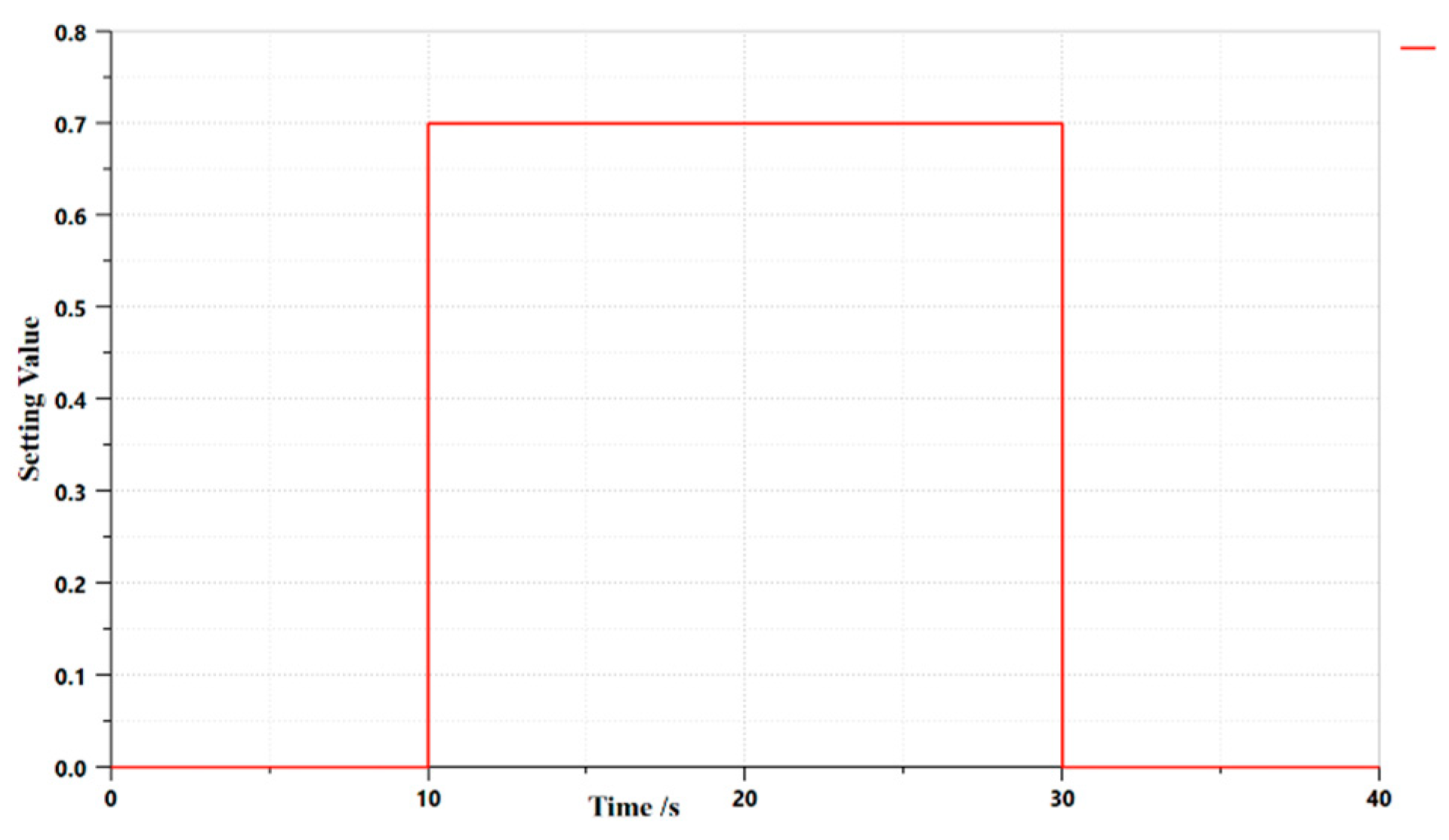
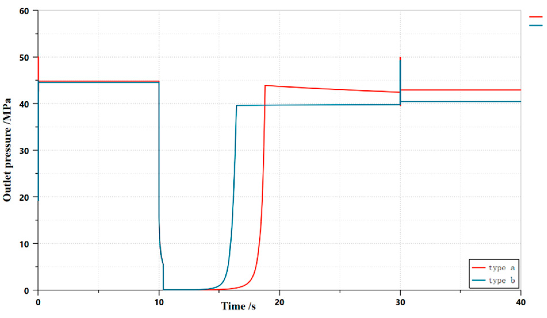
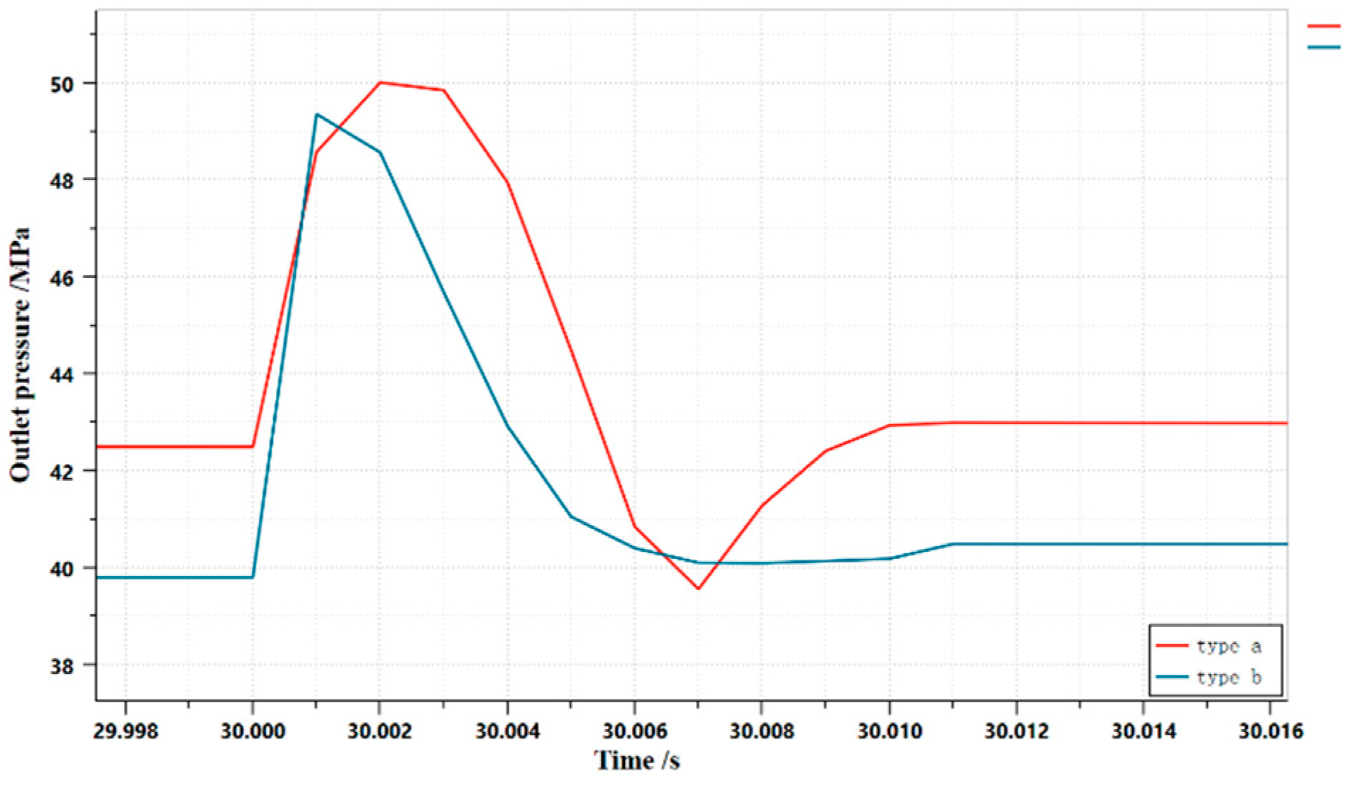
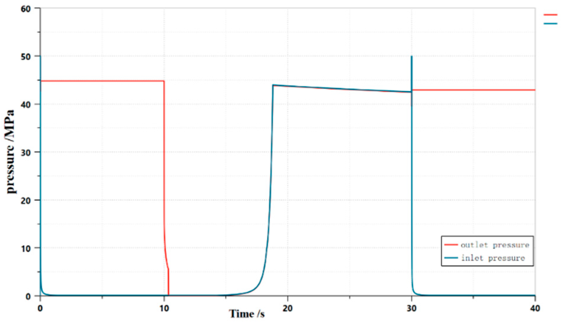
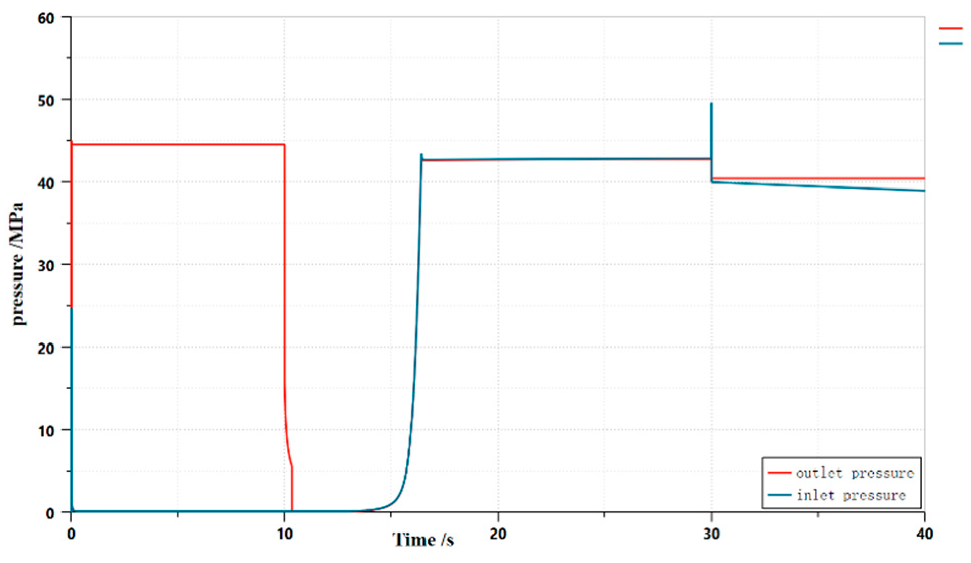
2.1.2. Creo Simulation Model
2.3. Mathematical modeling of the HLHMDCUV
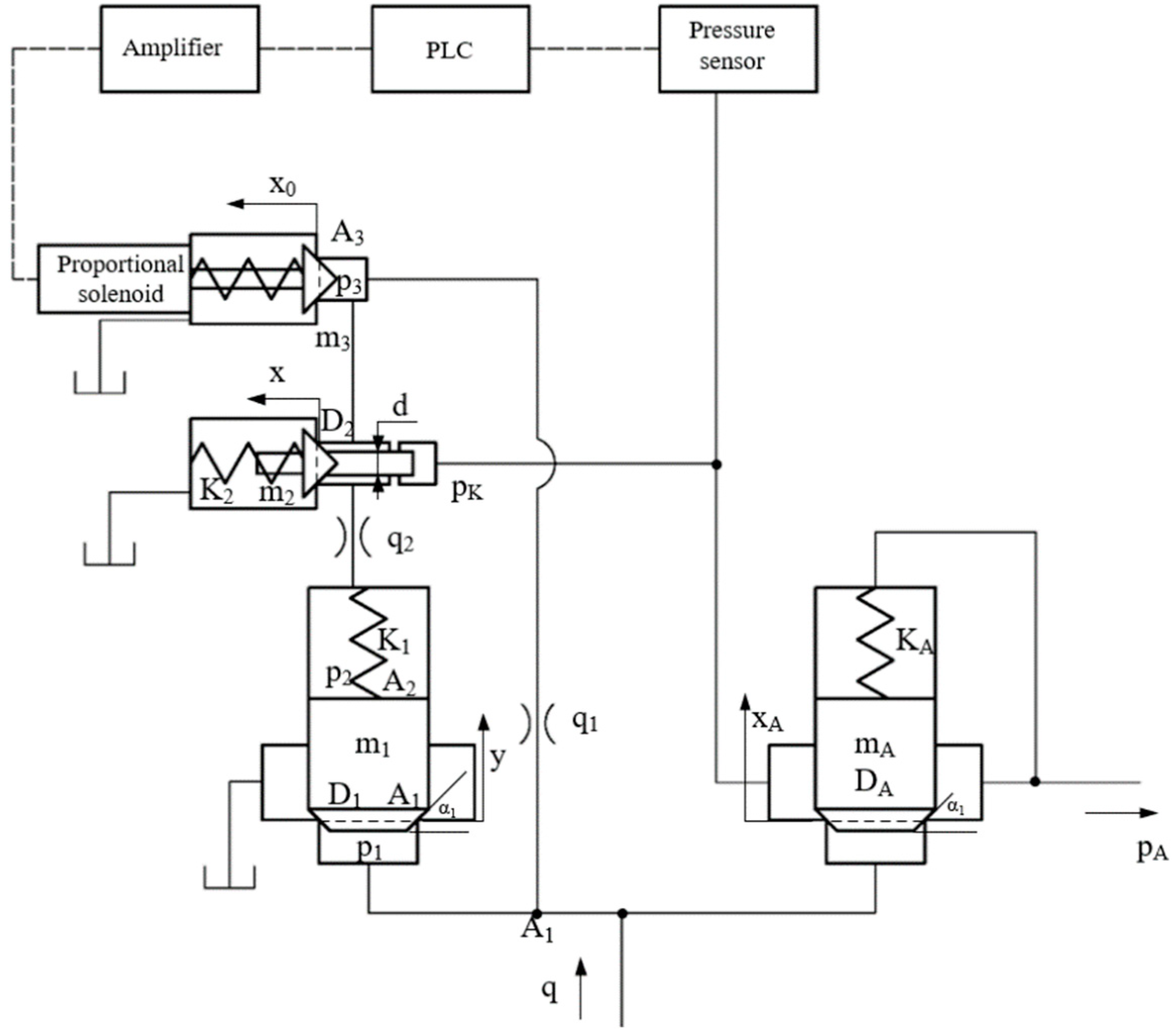
3. Results and conclusions
3.1. Dynamic characterization based on AMESim
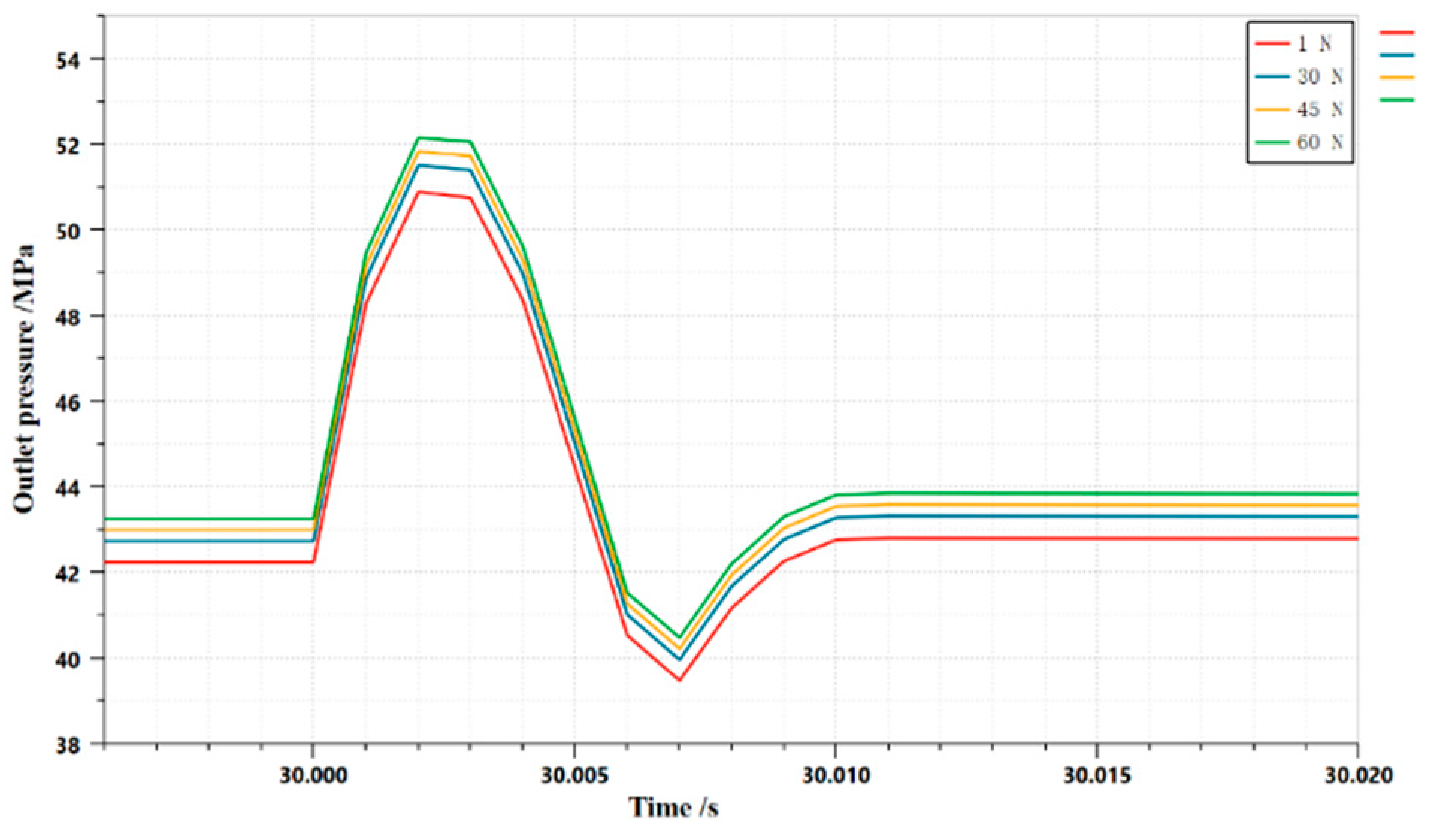
3.1.1. Effect of spring preload of digitally controlled pilot valve on dynamic characteristics of HLHMDCUV
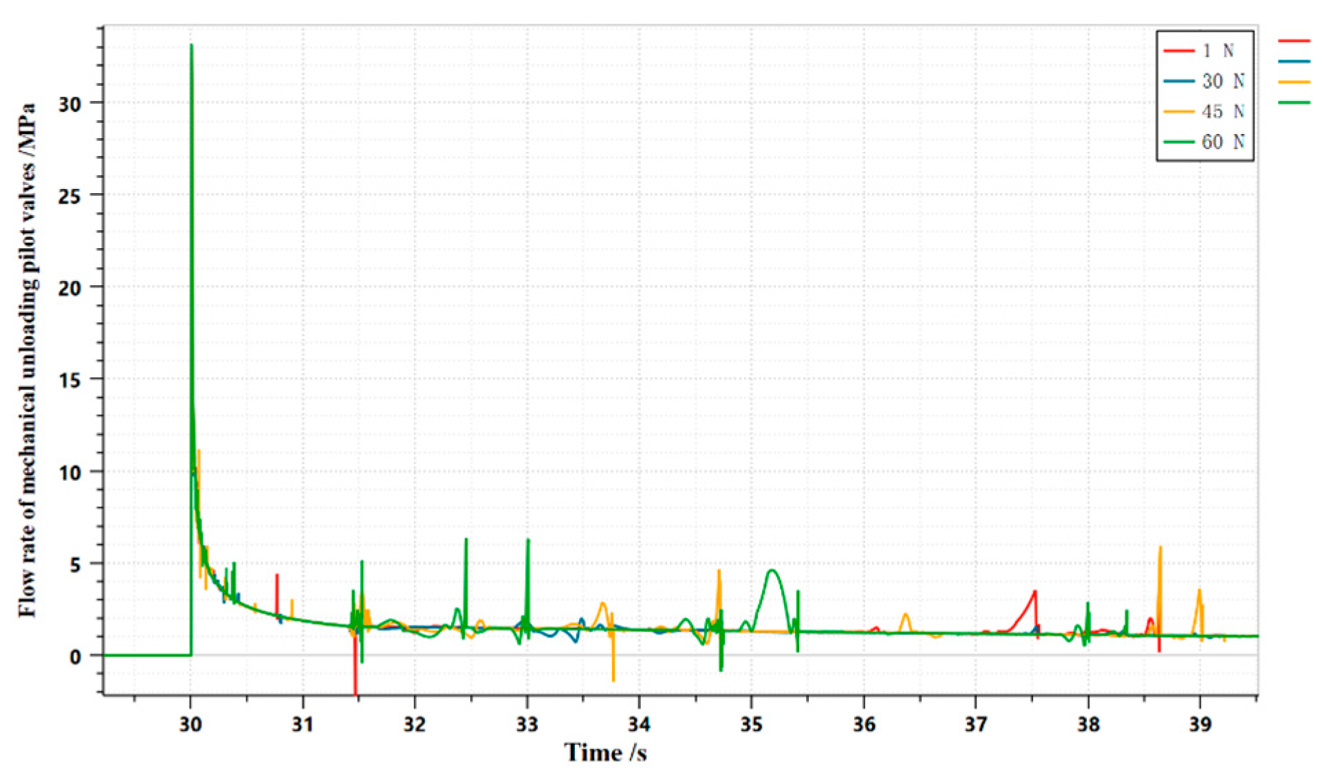
3.1.2. Effect of spring preload on the dynamic characteristics of HLHMDCUV by mechanical unloading pilot valve
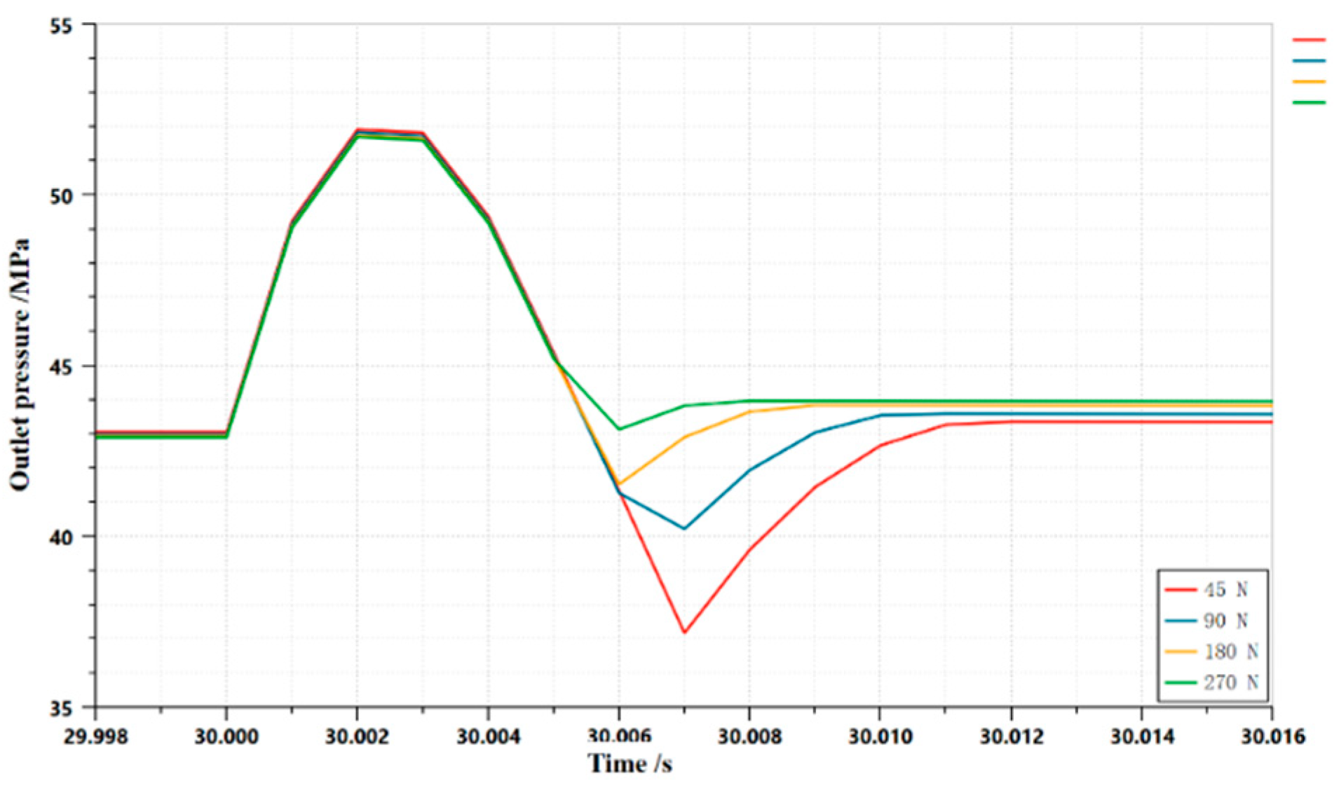
3.1.3. Effect of spring preload on the dynamic characteristics of HLHMDCUV for one-way main valves
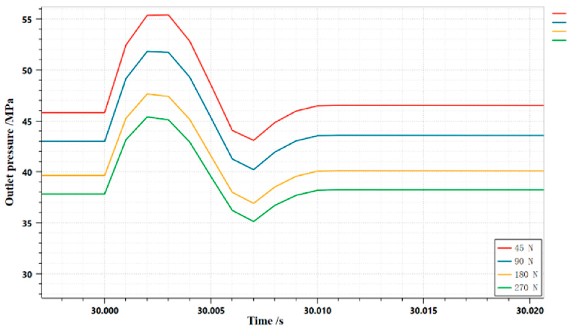
3.1.4. Effect of spring preload of unloading main valve on dynamic characteristics of HLHMDCUV
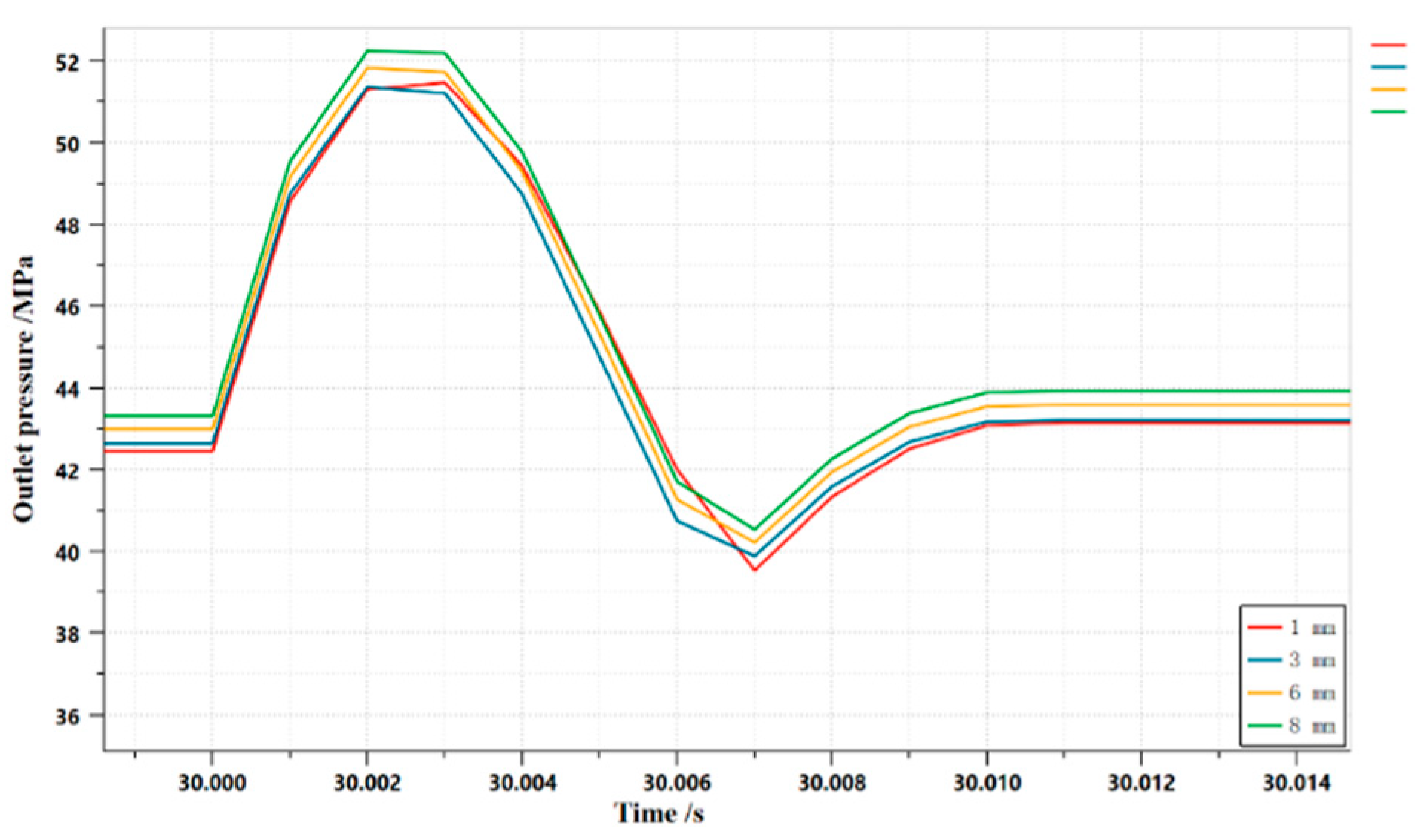
3.1.5. Effect of damping holes on dynamic properties
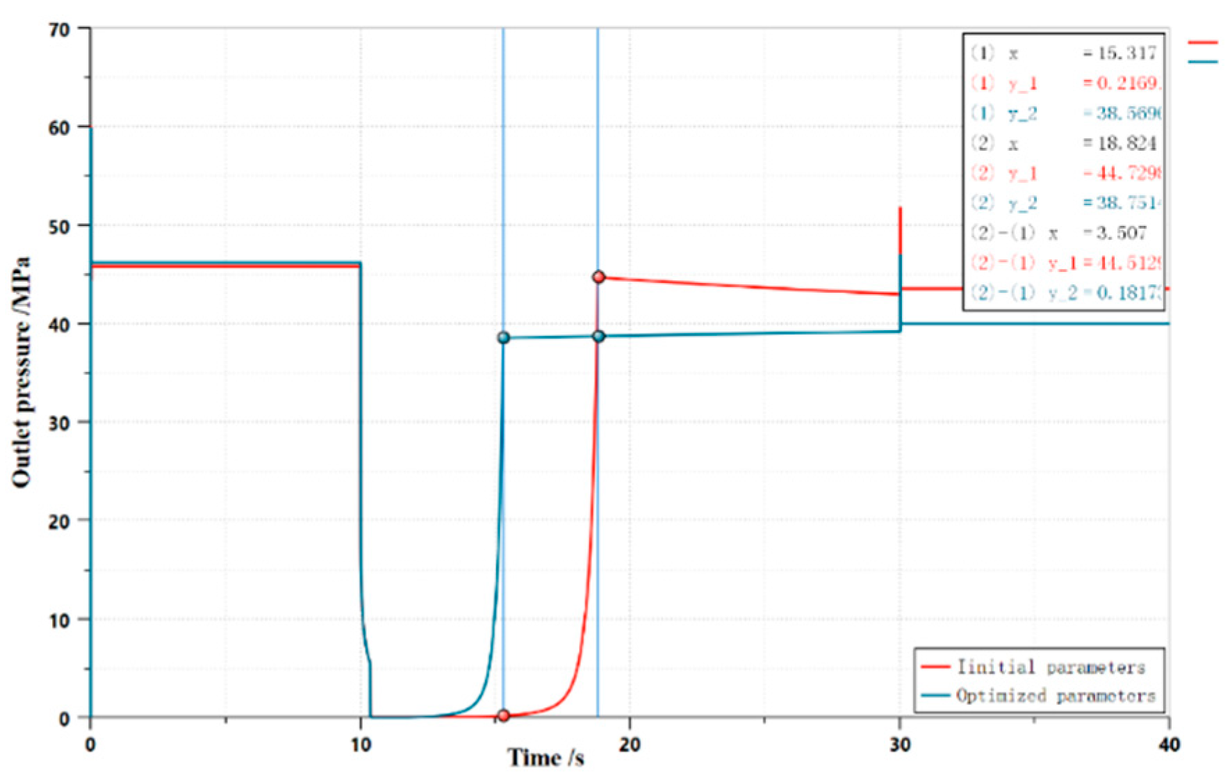
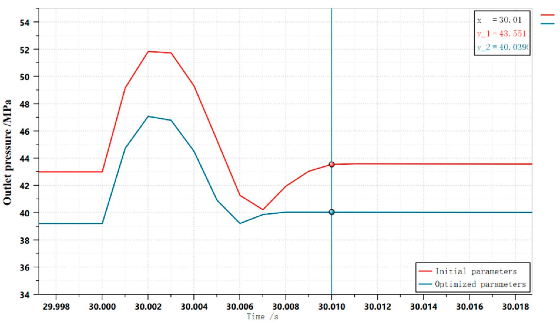
3.2. Structural optimization
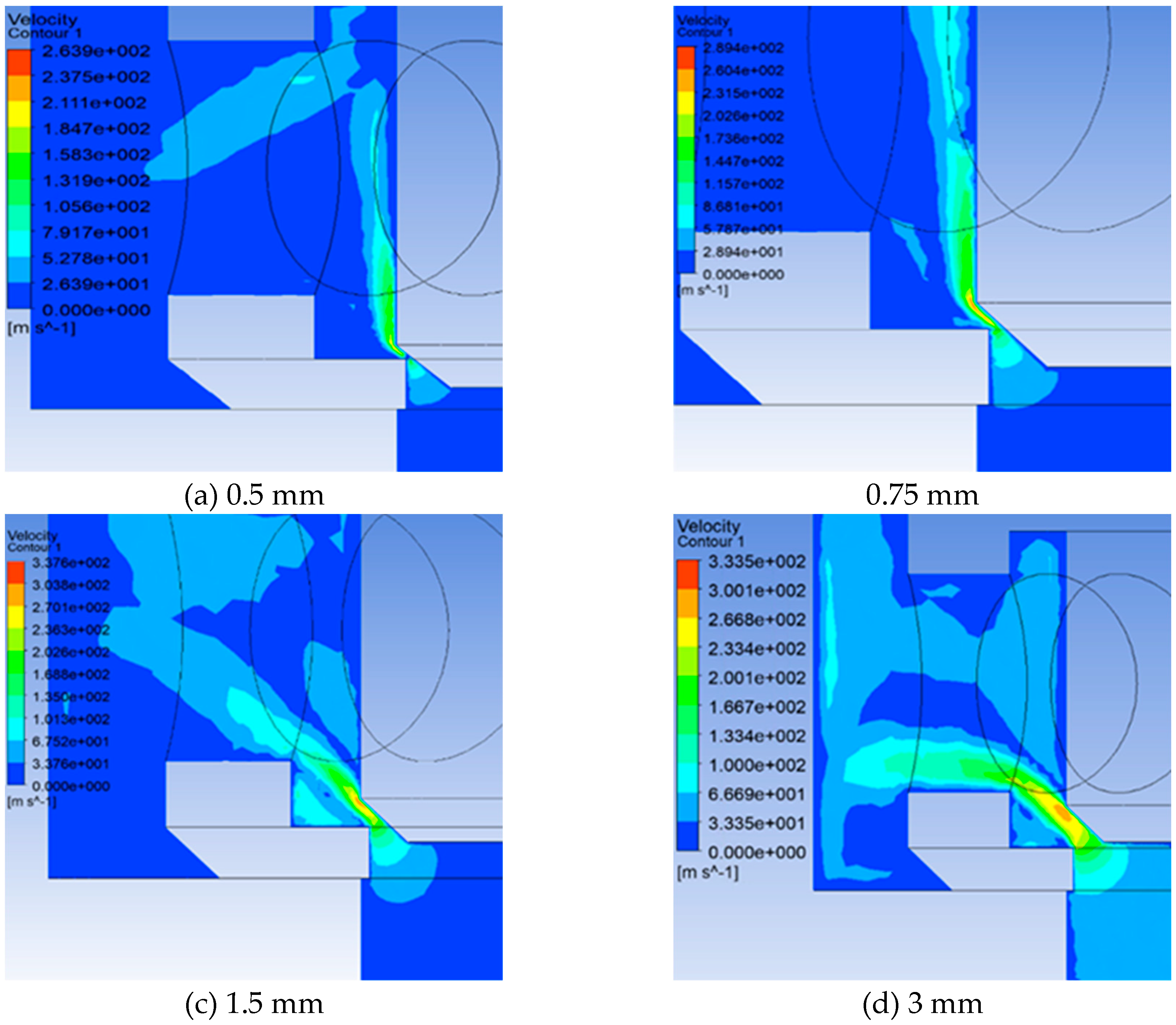
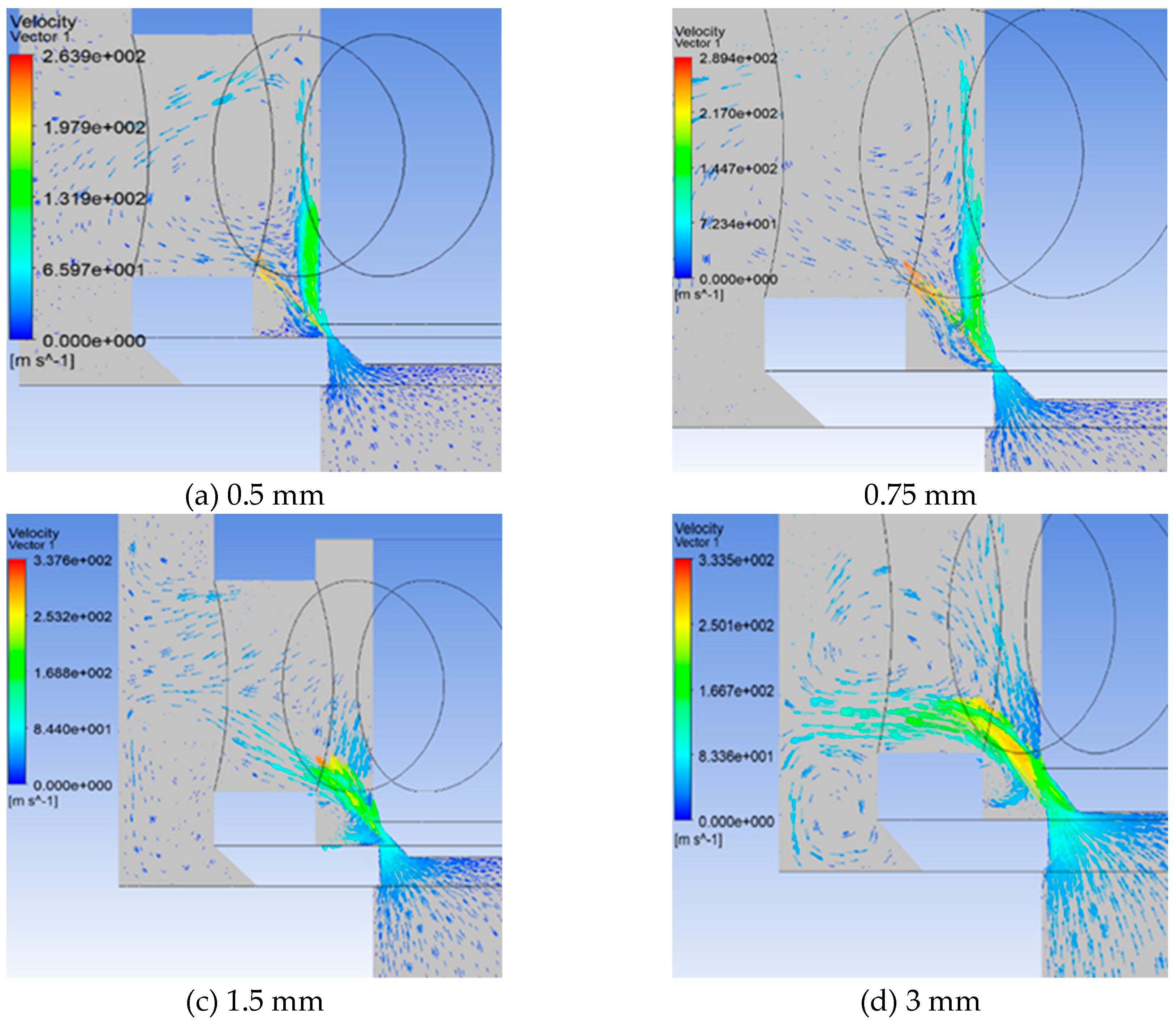
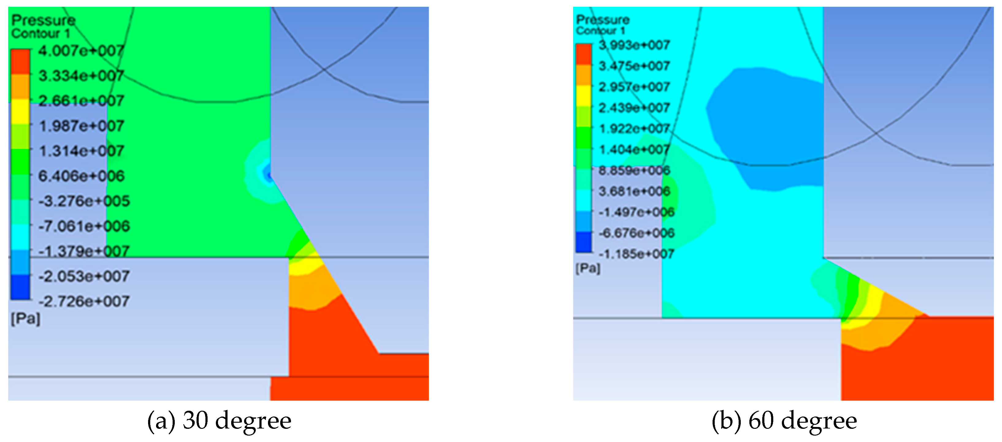
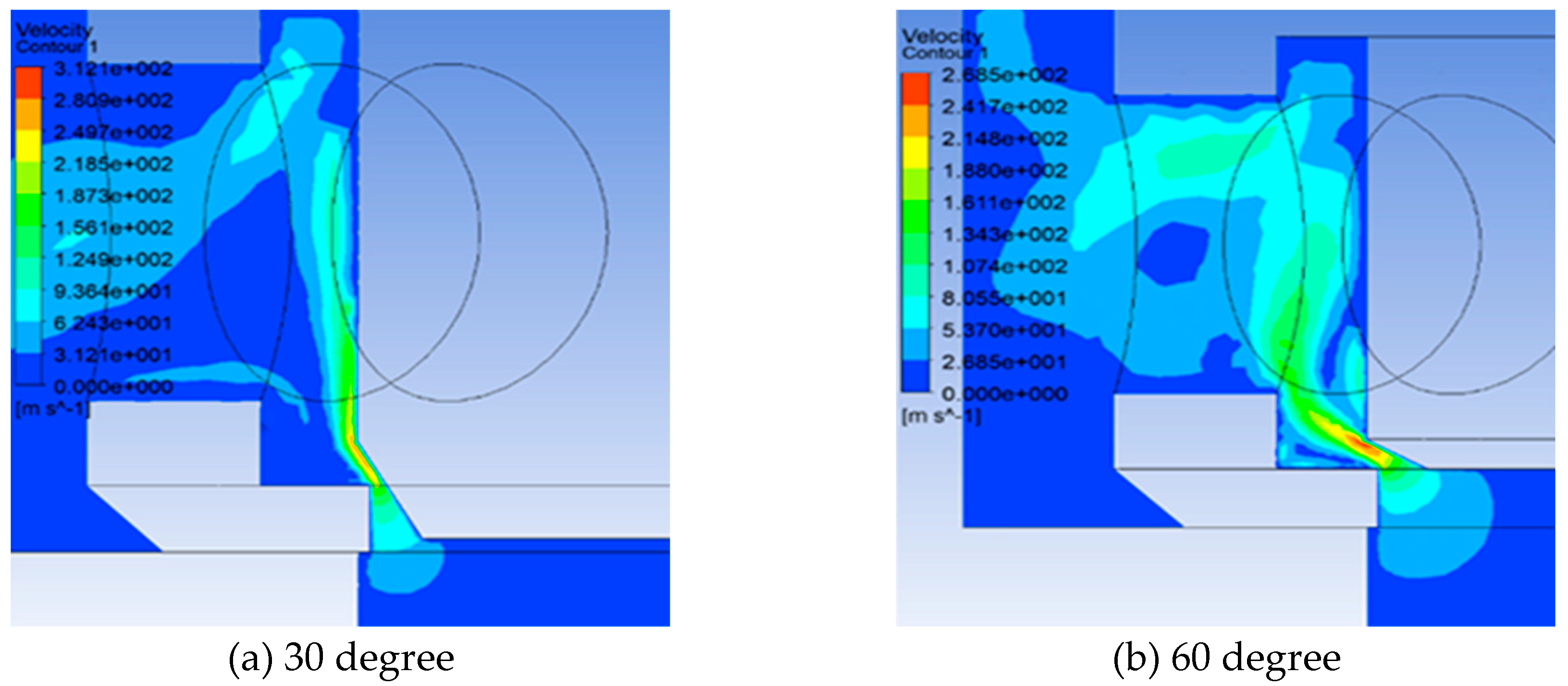
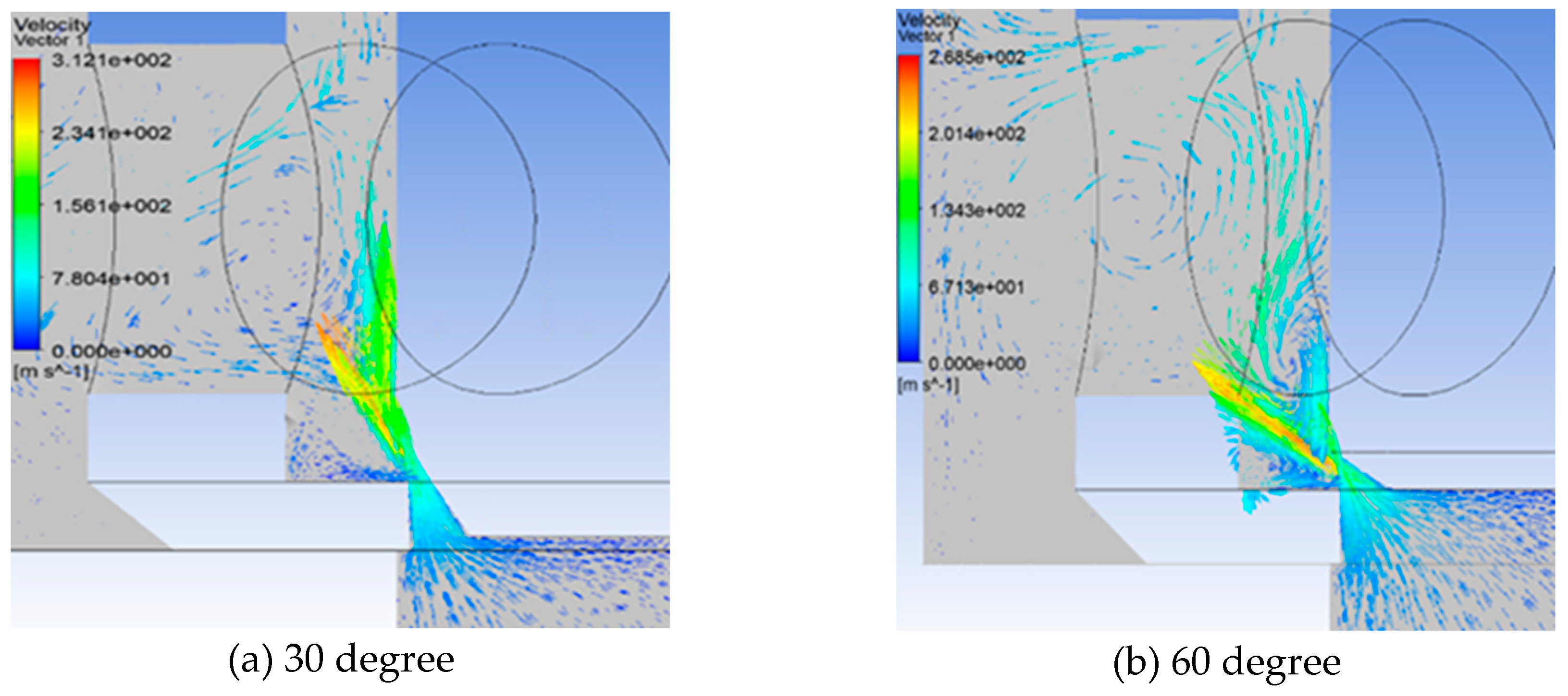
3.3. Simulation of the flow field inside the unloading main valve
3.3.1. Flow Field Simulation Model
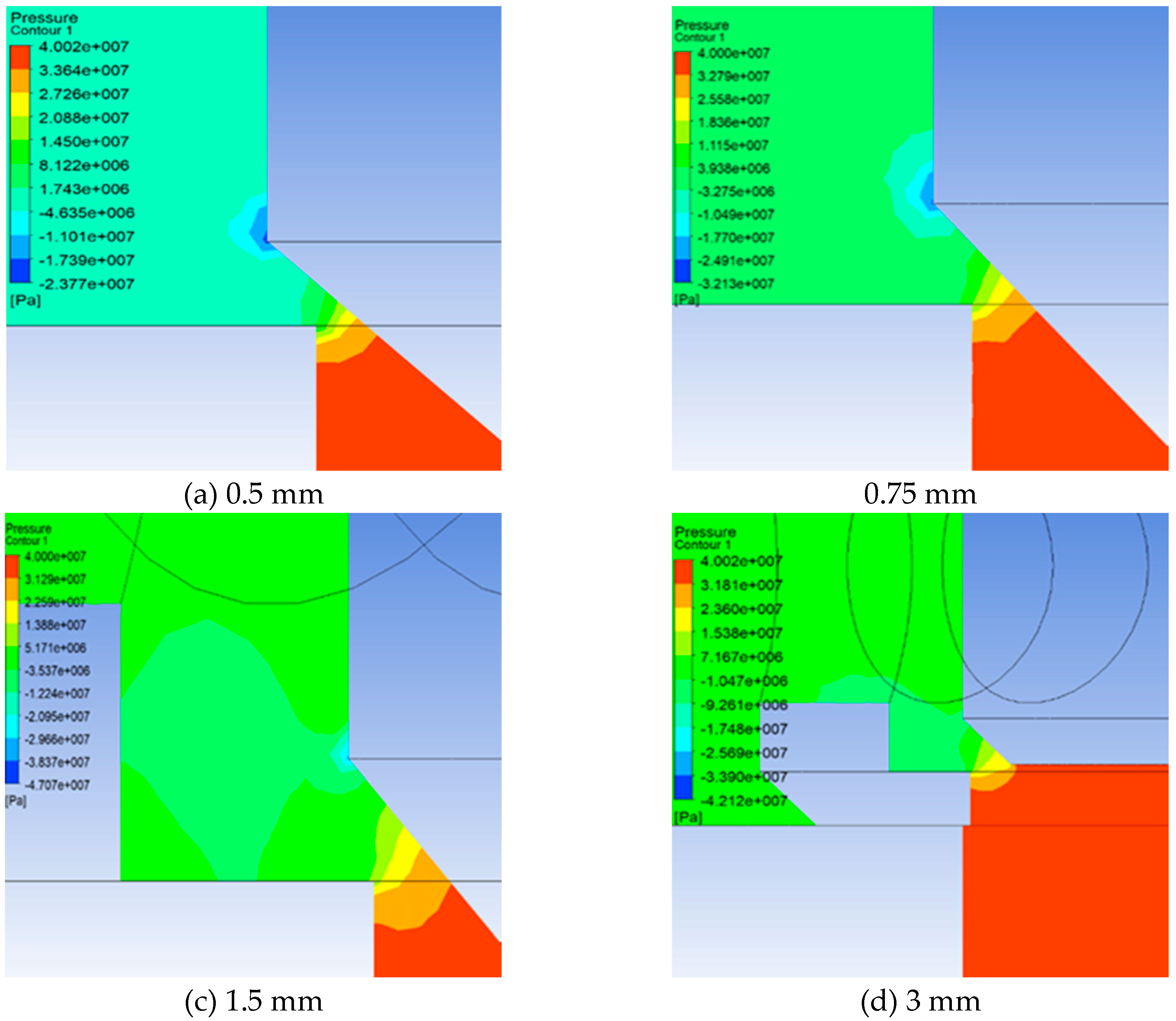
3.3.2. Analysis of results
4. HLHMDCUV Manufacturing and Applications
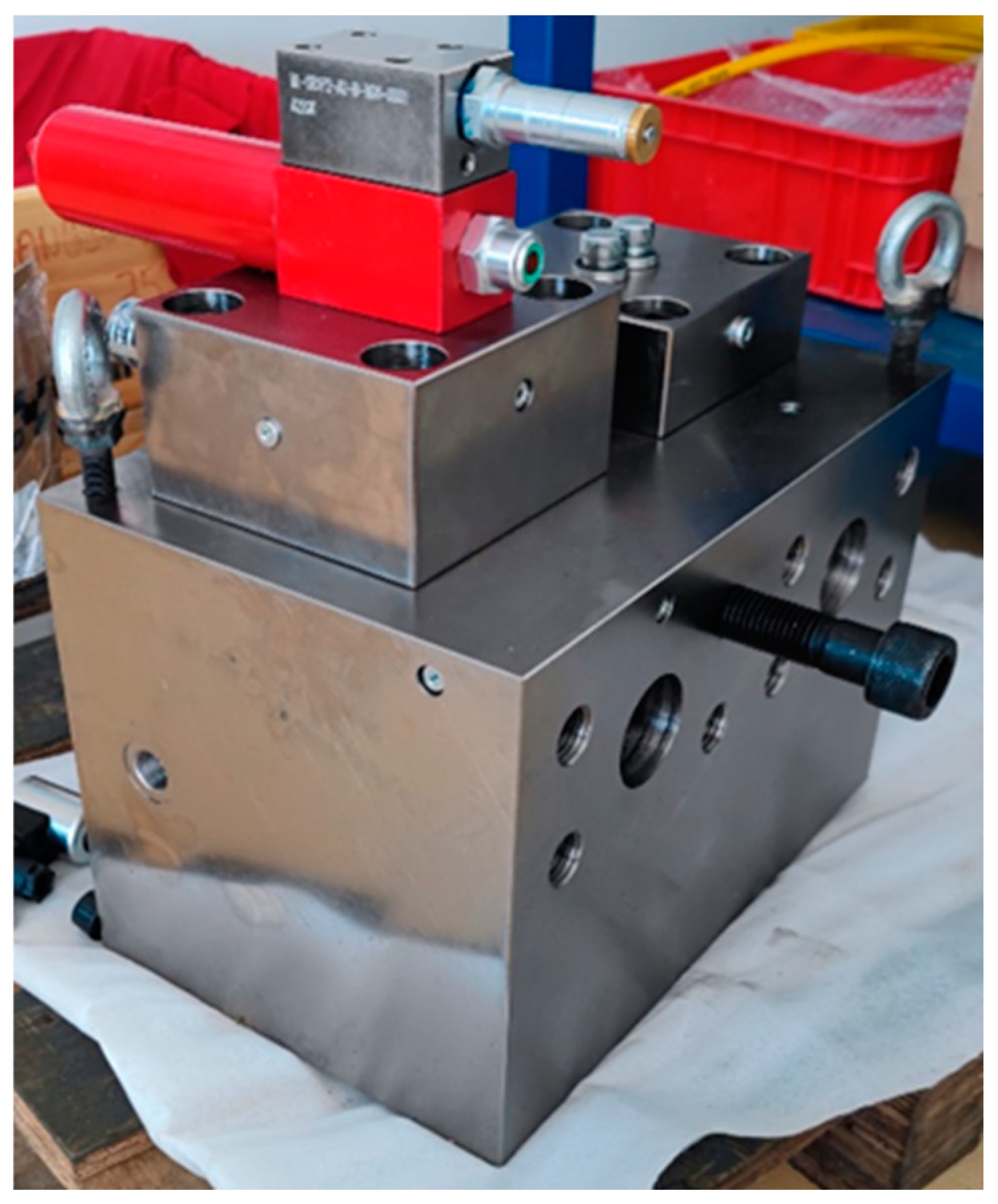
4.1. Manufacture of the HLHMDCUV

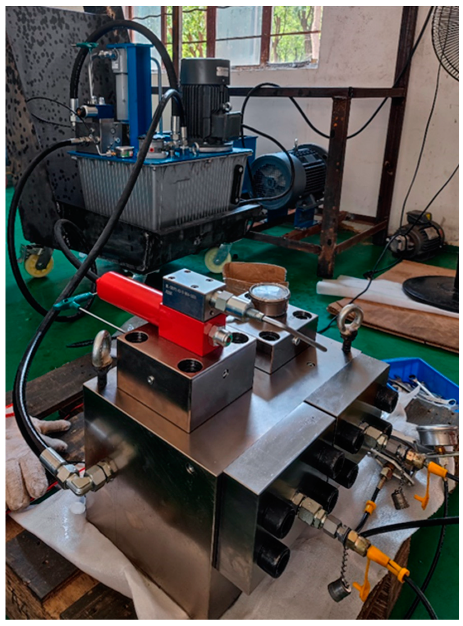
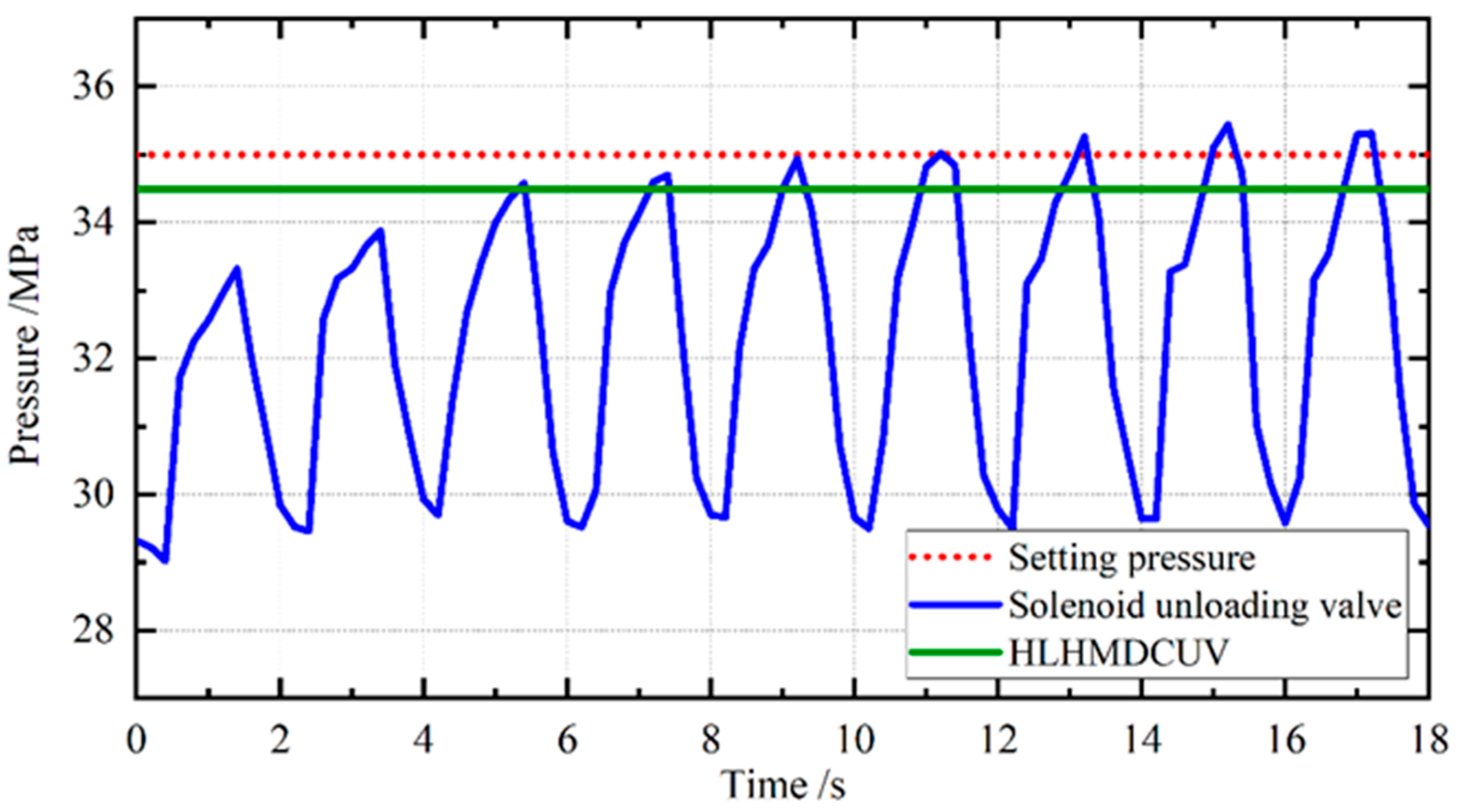
4.2. Application of HLHMDCUV
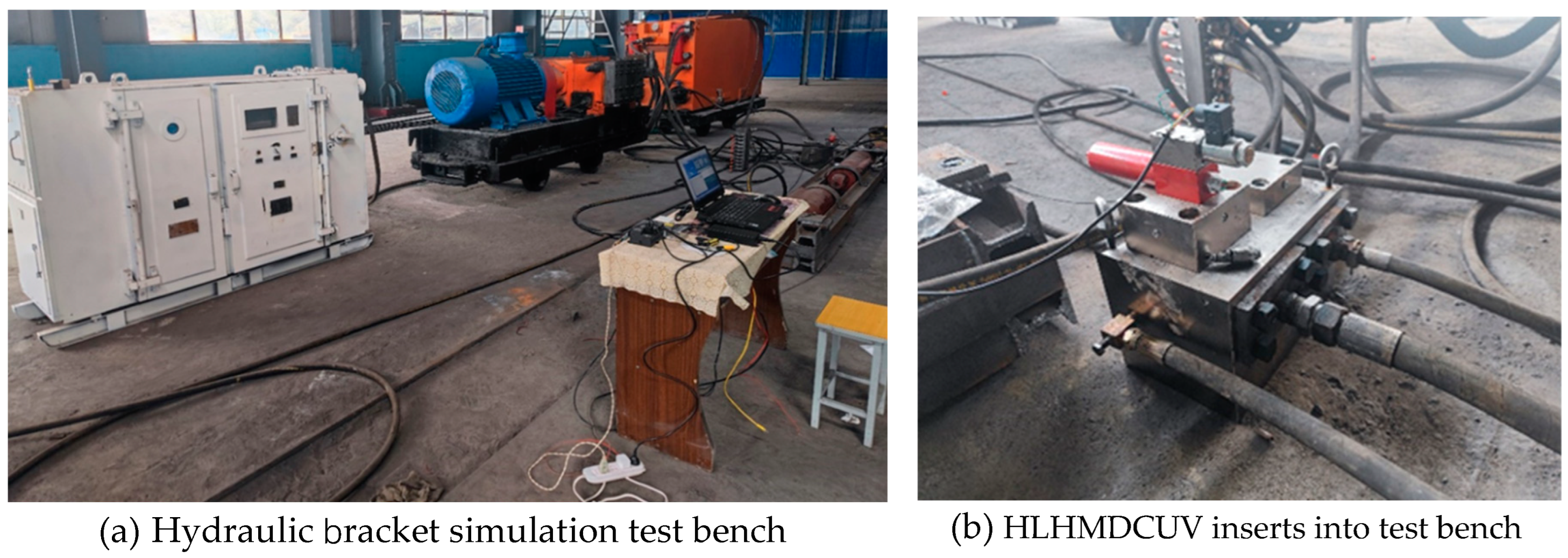
5. Conclusion
Funding
Conflicts of Interest
References
- J. P. Leng, K. L. Xing, and P. P. Zhang, “Dynamic analysis of cartridge style pilot relief valves,” Applied Mechanics and Materials, vol. 405–408, pp. 3279–3283, 2013. [CrossRef]
- C. J. Sang and J. H. Kang, “Orifice design of a pilot-operated pressure relief valve,” Journal of Pressure Vessel Technology, vol. 139, no. 3, 2017. [CrossRef]
- K. Dasgupta and J. Watton, “Dynamic analysis of proportional solenoid controlled piloted relief valve by bondgraph,” Simulation Modelling Practice and 5eory, vol. 13, no. 1, pp. 21–38, 2005. [CrossRef]
- K. Dasgupta and R. Karmakar, “Dynamic analysis of pilot operated pressure relief valve,” Simulation Modelling Practice & 5eory, vol. 10, no. 1-2, pp. 35–49, 2002. [CrossRef]
- X. Lei and Y. Wu, “Simulation and result analysis of AMEsim for the relief valve dynamic characteristics experiment,” in Proceedings of the International Conference on Electrical and Control Engineering, pp. 5587–5590, Wuhan, China, June 2010. [CrossRef]
- C. Vallet, J. Ferrari, J. F. Rit et al., “Single phase CFD inside a water safety valve,” in Proceedings of the ASME 2010 Pressure Vessels and Piping Division/K-PVP Conference, pp. 335–342, Bellevue, WA, USA, July 2010.
- Q. H. Hao, W. R. Wu, X. J. Liang, and Z. Liu, “Effects of Structure Parameters on Abnormal Opening of Pilot-Operated Relief Valve Under Alternating Pressurem,” IEEE Access, vol. 7, pp. 33932–33942, 2019. [CrossRef]
- Y. Deng and Z. Liu, “Optimal design of pilot proportional relief valve’s structural parameters in giant forging hydraulic press,” in Proceedings of the Second International Conference on Intelligent System Design and Engineering Application, pp. 412–416, IEEE, Hainan, China, January 2012.
- Gad, “Comprehensive nonlinear modeling of a pilot operated relief valve,” Journal of Dynamic Systems Measurement & Control, vol. 135, no. 1, Article ID 011011, 2013. [CrossRef]
- G. Yongjun, W. Zuwen, X. Jie, and Z. Zengmeng, “Simulation and experiments study on water hydraulic pressure relief valve with pilot stage,” Journal of Mechanical Engineering, vol. 46, no. 24, pp. 136–142, 2010.
- Y. Zhongjiong, L. Hongbin, Z. Liqiang, and L. Yaozhong, “Simulation of self-excited vibration behavior of pilot valve core on pilot-operated pressure relief valve with strong vibration,” Journal of Huazhong University of Science and Technology, vol. 43, no. 4, pp. 58–63, 2015.
- J. Ruan, P. R. Ukrainetz, and R. Burton, “Frequency domain modelling and identification of 2D digital servo valve,” International Journal of Fluid Power, vol. 1, no. 2, pp. 49–59, 2000. [CrossRef]
- M. Xuyao, L. Bin, L. Yiou, H. Junhua, and L. Qiwei, “Design & simulation of a hydraulic back pressure valve with a large flow range,” Journal of Physics: Conference Series, vol. 1213, no. 4, 2019. [CrossRef]
- X. Y. Mao and J. H. Hu, “Characteristic Analysis of a Water Hydraulic Pilot-operated Pressure-Reducing Valve,” in Proceedings of 3rd International Conference on Advances in Energy, Environment and Chemical Engineering, vol. 69, Chengdu, China, May 2017. [CrossRef]
- E. Lisowski and G. Filo, “Analysis of a proportional control valve flow coefficient with the usage of a CFD method,” Flow Measurement and Instrumentation, vol. 53, pp. 269–278, 2017. [CrossRef]
- M. Georgy, “Makaryants. Fatigue failure mechanisms of a pressure relief valve,” Journal of Loss Prevention in the Process Industries, vol. 48, pp. 1–13, 2017.
- G. Mu, F. Wang, X. Mi, and G. Gao, “Dynamic modeling and analysis of compressor reed valve based on movement characteristics,” Applied 5ermal Engineering, vol. 150, pp. 522–531, 2019. [CrossRef]
- V. Sverbilov, D. Stadnick, and G. Makaryants, “Study on dynamic behavior of a gas pressure relief valve for a big flow rate,” in Proceedings of the ASME/BATH 2013 Symposium on Fluid Power and Motion Control, Sarasota, FL, USA, October 2013.
- Qing-liang Zeng , Ming-qian Tian,Characteristic Analysis of Digital Large Flow Emulsion Relief Valve. Hindawi Mathematical Problems in Engineering Volume 2020, Article ID 5820812, 18 pages. [CrossRef]

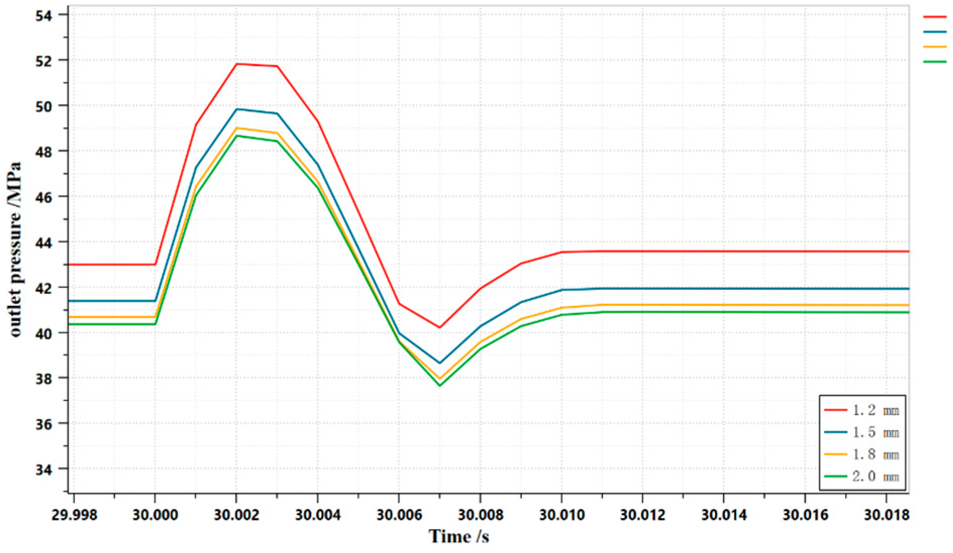
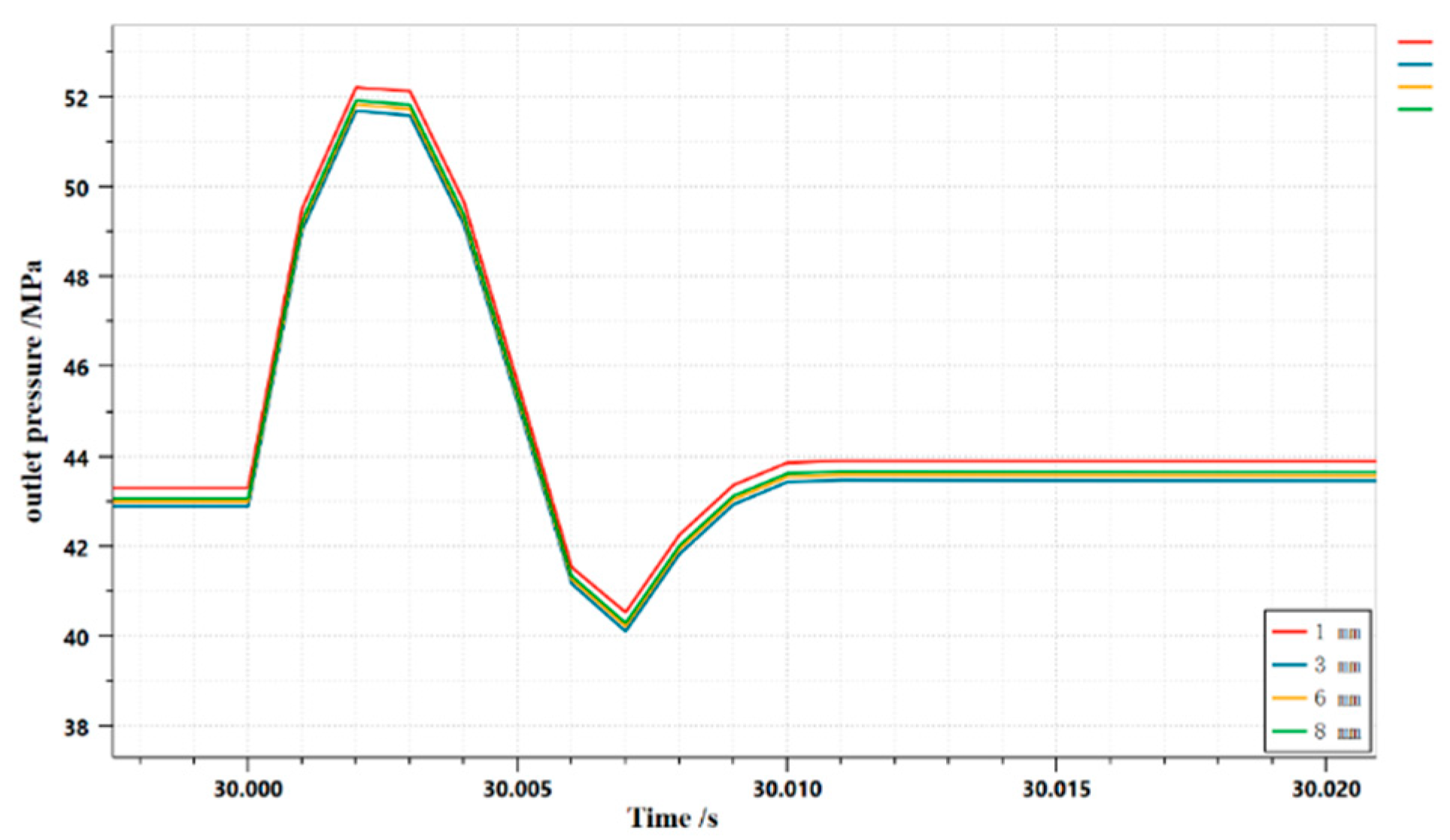
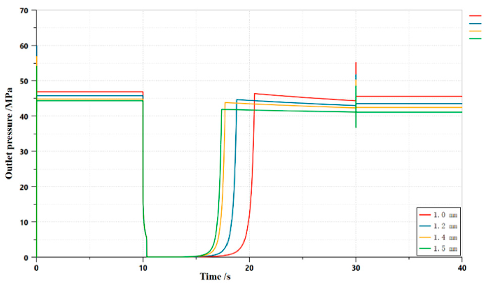
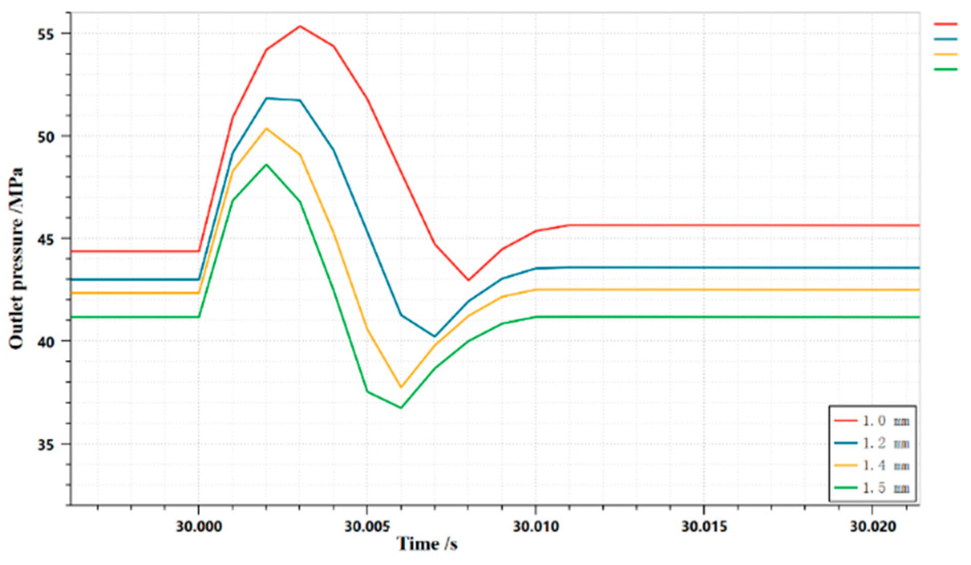
| Structral parameter | Value |
|---|---|
|
Diameter of poppet of one-way main spool valve Diameter of hole of one-way main spool valve Spring preload of one-way main spool valve Diameter of poppet of unloading main spool Diameter of hole of unloading main spool Spring preload of unloaded main spool Diameter of hole of digitally controlled pilot valve Spring preload for digitally controlled pilot valves Diameter of poppet of mechanical unloading pilot valve Diameter of rod of mechanical unloading pilot valve Spring preload for mechanical unloading pilot valves Length of the damping hole in front of the pilot valve cavity Diameter of the damping hole in front of the pilot valve cavity Length of the damping hole in the upper chamber of the unloading main valve Diameter of the damping hole in the upper chamber of the unloading main valve |
56 mm 50 mm 90 N 56 mm 50 mm 90 N 3 mm 45 N 5 mm 4 mm 360π N 6 mm 1.2 mm 6 mm 1.2 mm |
| Structral parameter | Value |
|---|---|
|
Diameter of poppet of one-way main spool valve Diameter of hole of one-way main spool valve Spring preload of one-way main spool valve Diameter of poppet of unloading main spool Diameter of hole of unloading main spool Spring preload of unloaded main spool Diameter of hole of digitally controlled pilot valve Spring preload for digitally controlled pilot valves Diameter of poppet of mechanical unloading pilot valve Diameter of rod of mechanical unloading pilot valve Spring preload for mechanical unloading pilot valves Length of the damping hole in front of the pilot valve cavity Diameter of the damping hole in front of the pilot valve cavity Length of the damping hole in the upper chamber of the unloading main valve Diameter of the damping hole in the upper chamber of the unloading main valve |
56 mm 50 mm 270 N 56 mm 50 mm 180 N 3 mm 24 N 5 mm 4 mm 360π N 6 mm 1.2 mm 3 mm 1.2 mm |
Disclaimer/Publisher’s Note: The statements, opinions and data contained in all publications are solely those of the individual author(s) and contributor(s) and not of MDPI and/or the editor(s). MDPI and/or the editor(s) disclaim responsibility for any injury to people or property resulting from any ideas, methods, instructions or products referred to in the content. |
© 2023 by the authors. Licensee MDPI, Basel, Switzerland. This article is an open access article distributed under the terms and conditions of the Creative Commons Attribution (CC BY) license (http://creativecommons.org/licenses/by/4.0/).


