Submitted:
06 September 2023
Posted:
08 September 2023
You are already at the latest version
Abstract
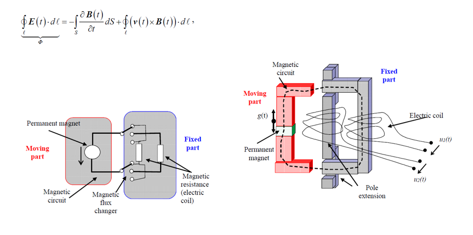
Keywords:
1. Introduction
2. Overview of the Current Status
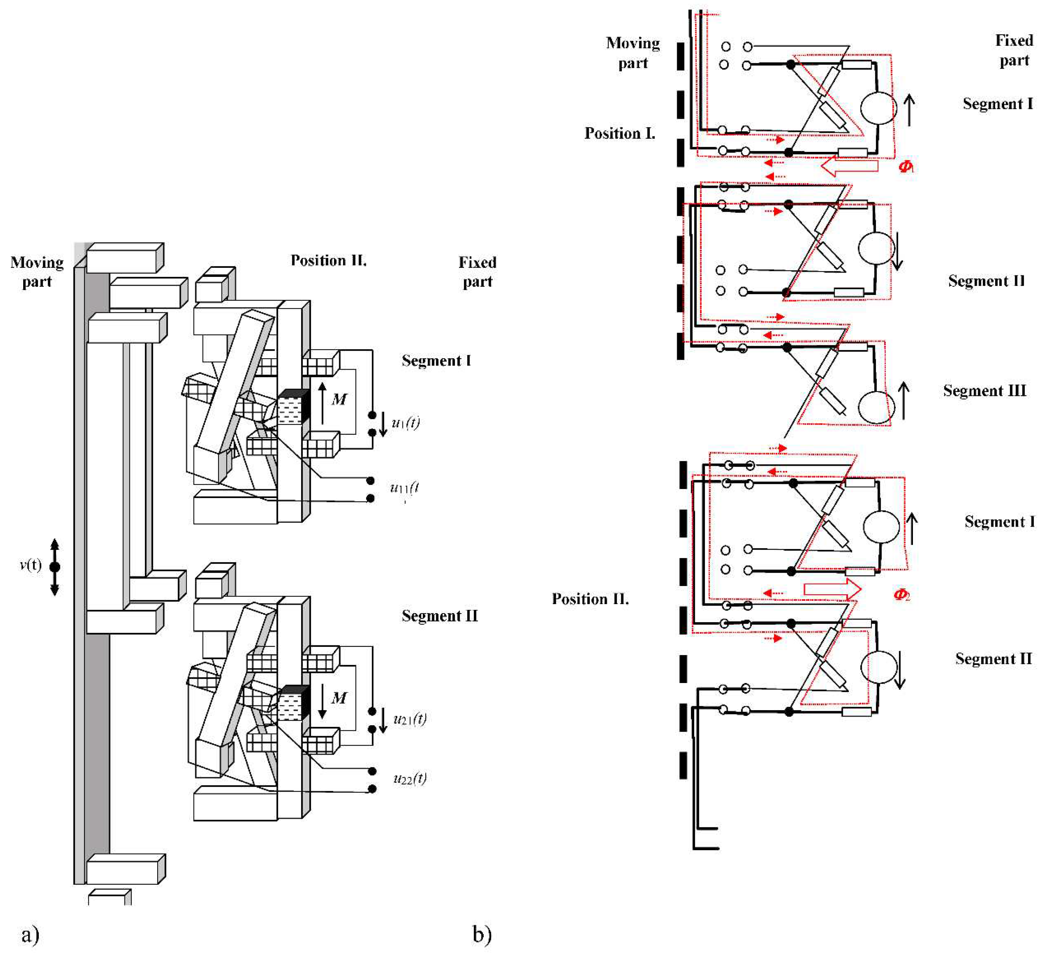
3. Design of Electromagnetic Transformation Method of Renewable Energy

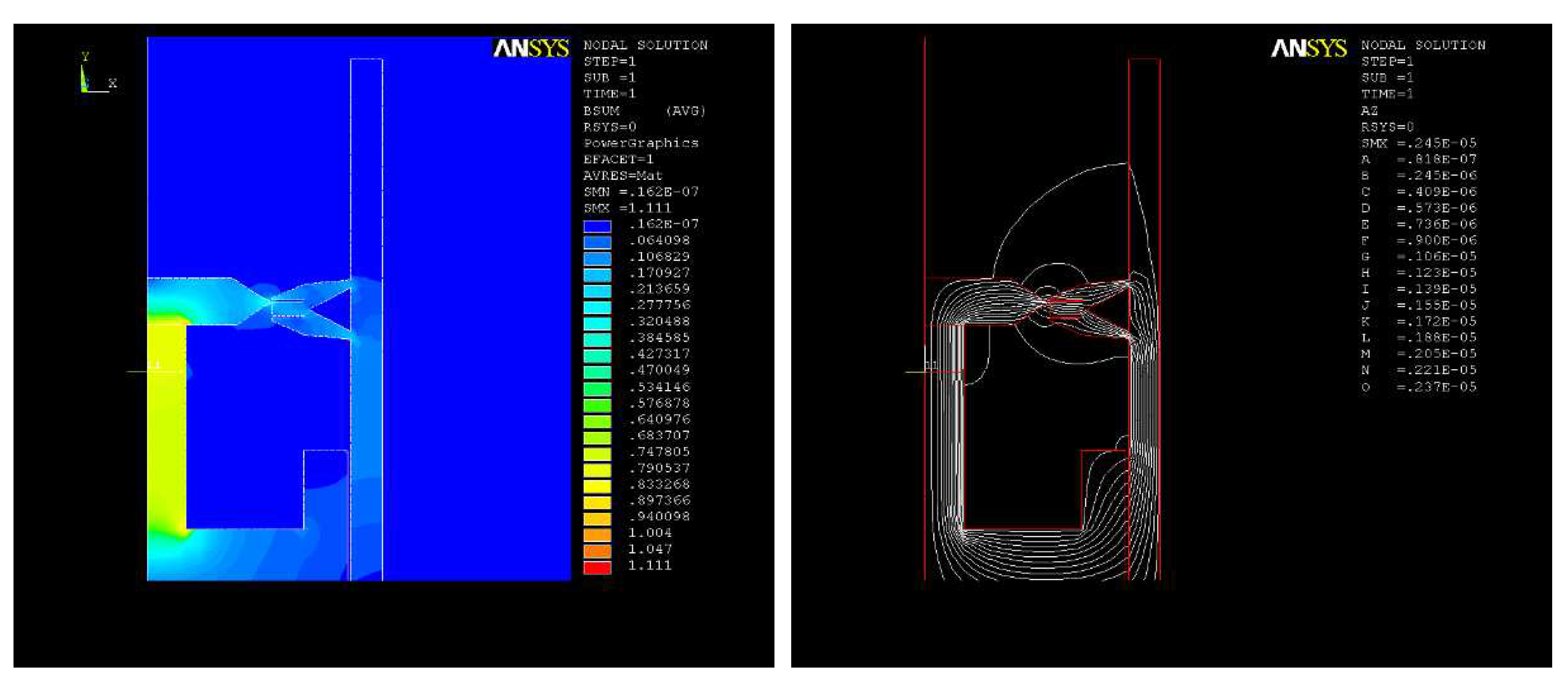
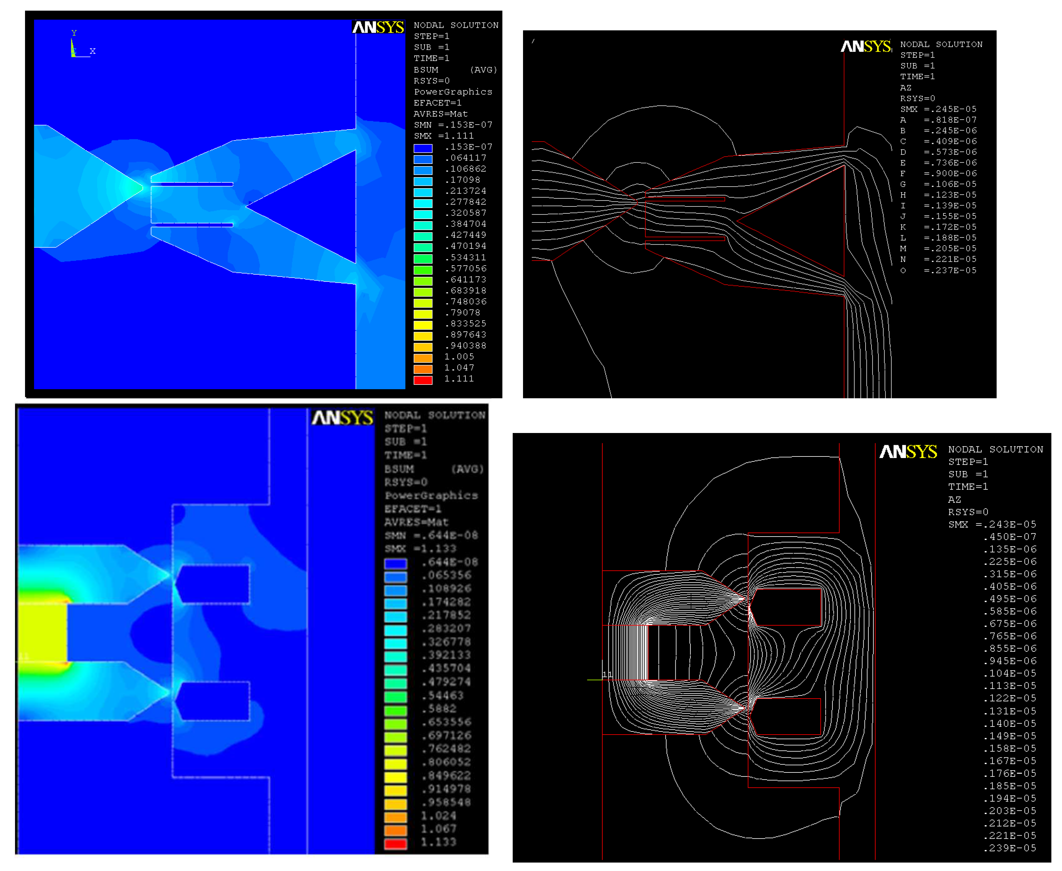
4. Experiments
5. Conclusions
Author Contributions
Acknowledgments
Conflicts of Interest
References
- Stratton, J.A., 1961. Theory of Electromagnetic Field. SNTL, Praha.
- Fiala, P., 2003. Vibration Generator Conception; Research report in Czech; DTEEE, Brno University of Technology: Brno, Czech Republic; p.
- Jirků, T., Fiala, P., Kluge, M., 2010. Magnetic resonant harvesters and power management circuit for magnetic resonant harvesters. Microsyst Technol 16, 677–690. [CrossRef]
- Fiala, P.; Jirků, T., n.d.,2014. Analysis and Design of a Minigenerator, in: Progress in Electromagnetics. Presented at the Progress in Electromagnetics PIERS 2014, PIERS USA Boston, in Guangzhou, China, pp. 749–753.
- Famouri, P., Cawthorne, W. R., Clark, N., Nandkumar, S., Atkinson, C., Atkinson, R., Petreanu, S., 1999. Design and testing of a novel linear alternator and engine system for remote electrical power generation. Paper presented at the IEEE Engineering Society, Winter Meeting, 1 108-112.
- Cawthorne, W.R., Famouri, P., Jingdong Chen, Clark, N.N., McDaniel, T.I., Atkinson, R.J., Nandkumar, S., Atkinson, C.M., Petreanu, S., 1999. Development of a linear alternator-engine for hybrid electric vehicle applications. IEEE Trans. Veh. Technol. 48, 1797–1802. [CrossRef]
- K. M. Nor, H. Arof and Wijono, 2004. Design of a 5 kW tubular permanent magnet linear generator. 39th International Universities Power Engineering Conference. UPEC 2004., Bristol, UK, 2004, pp. 528-532 vol. 1.
- Takahara, K., Ohsaki, S., Itoh, Y., Ohyama, K., & Kawaguchi, H., 2009. Characteristic analysis and trial manufacture of permanent-magnetic type linear generator. Electrical Engineering in Japan (English Translation of Denki Gakkai Ronbunshi), 166(3), 94-100. [CrossRef]
- Li, W., Shuang Gao, Diyun Wu, Zhang, X., 2010. Design of a linear magnetic-geared free-piston generator for series hybrid electric vehicles, in: 2010 IEEE Vehicle Power and Propulsion Conference. Presented at the 2010 IEEE Vehicle Power and Propulsion Conference (VPPC), IEEE, Lille, France, pp. 1–6. [CrossRef]
- Fazal, I., Karsiti, M.N., Zulkifli, S.A., Ibrahim, T., Rao, K.S.R., 2010. Modeling and simulation of a moving-coil linear generator, in: 2010 International Conference on Intelligent and Advanced Systems. Presented at the Advanced Systems (ICIAS 2010), IEEE, Kuala Lumpur, Malaysia, pp. 1–5. [CrossRef]
- Hernandez, I., Segundo, J., Gonzalez, X., Luna, D., Juarez, Z., 2017. Performance and power quality assessment of a linear electric generator focused on microgeneration applications. Int. Trans. Electr. Energ. Syst. 27, e2326. [CrossRef]
- Zou, H., Wang, M., Tang, M., Li, C., Tian, C., 2017. Experimental investigation and performance analysis of a direct-driven linear generator. Energy Procedia 142, 284–290. [CrossRef]
- Yamanaka, Y., Nirei, M., Sato, M., Murata, H., Yinggang, B., Mizuno, T., 2017. Design of linear synchronous generator suitable for free-piston engine linear generator system, in: 2017 11th International Symposium on Linear Drives for Industry Applications (LDIA). Presented at the 2017 11th International Symposium on Linear Drives for Industry Applications (LDIA), IEEE, Osaka, pp. 1–4. [CrossRef]
- Abdalla, I. I., Zainal A., E. Z., Anwarudin, A. R. T., Firmansyah, Aziz, A. R. A., & Heikal, M. R., 2017. Cogging force issues of permanent magnet linear generator for electric vehicle. Journal of Electrical Systems, 13(3), 489-502.
- Baker, Nick.J., Sa Jalal, A., Wang, J., Korbekandi, R.M., 2019. Experimental comparison of two linear machines developed for the free piston engine. J. eng. 2019, 4406–4410. [CrossRef]
- Subramanian, J., Mahmudzadeh, F., Bade, M., Famouri, P., 2019. Simulation and Experimental Validation of Equivalent Circuit Parameters and Core Loss in a Tubular Permanent Magnet Linear Generator for Free Piston Engine Applications, in: 2019 IEEE International Electric Machines & Drives Conference (IEMDC). Presented at the 2019 IEEE International Electric Machines & Drives Conference (IEMDC), IEEE, San Diego, CA, USA, pp. 57–62. [CrossRef]
- Fiala, P., Szabo, Z., Marcon, P., & Roubal, Z., 2017. Mini- and microgenerators applicable in the MEMS technology. Paper presented at the Proceedings of SPIE - the International Society for Optical Engineering, 10246. [CrossRef]
- Atkinson, C. M., Petreanu, S., Clark, N. N., Atkinson, R. J., McDaniel, T. I., Nandkumar, S., & Famouri, P., 1999. Numerical simulation of a two-stroke linear engine-alternator combination. [CrossRef]
- Mikalsen, R., & Roskilly, A. P., 2008. Performance simulation of a spark ignited free-piston engine generator. Applied Thermal Engineering, 28(14-15), 1726-1733. [CrossRef]
- Rinderknecht, F., & Herzog, H., 2011. A high efficient energy converter for a hybrid vehicle concept – gas spring focused. EVER Monaco 2011.
- Guo, C. , Feng, H., Jia, B., Zuo, Z., Guo, Y., & Roskilly, T., 2017. Research on the operation characteristics of a free-piston linear generator: Numerical model and experimental results. Energy Conversion and Management, 131, 32-43. [CrossRef]
- Yuan, C. , Feng, H., & He, Y., 2017. An experimental research on the combustion and heat release characteristics of a free-piston diesel engine generator. Fuel, 188, 390-400. [CrossRef]
- Jia, B. , Wu, D., Smallbone, A., Lawrence, C., & Roskilly, A. P., 2018. Design, modelling and validation of a linear joule engine generator designed for renewable energy sources. Energy Conversion and Management, 165, 25-34. [CrossRef]
- Clark, N.N. , McDaniel, T.I., Atkinson, R.J., Nandkumar, S., Atkinson, C., Petreanu, S., Famouri, P., 1998. Modeling and development of a linear engine. Paper No. 1998; -95. [Google Scholar]
- Fredriksson, J. , Denbratt, I., 2004. Simulation of a Two-Stroke free Piston Engine. Paper No. 2004. [Google Scholar]
- 9455; 0.
- Li, Q. , Xiao, J., & Huang, Z., 2008. Simulation of a two-stroke free-piston engine for electrical power generation. Energy and Fuels, 22(5), 3443-3449. [CrossRef]
- Feng, H. , Song, Y., Zuo, Z., Shang, J., Wang, Y., & Roskilly, A. P., 2015. Stable operation and electricity generating characteristics of a single-cylinder free piston engine linear generator: Simulation and experiments. Energies, 8(2), 765-785. [CrossRef]
- Sun, P. , Zhang, C., Chen, J., Zhao, F., Liao, Y., Yang, G., & Chen, C., 2017. Hybrid system modeling and full cycle operation analysis of a two-stroke free-piston linear generator. Energies, 10(2). [CrossRef]
- Pavelka, J. , 2008. Analysis of combustion engine - electric linear generator set operation, in: 2008 13th International Power Electronics and Motion Control Conference. Presented at the 2008 13th International Power Electronics and Motion Control Conference (EPE/PEMC 2008), IEEE, Poznan, Poland, pp. 988–993. [CrossRef]
- Tikkanen, R.S. , Vilenius, M., 1999. Hydraulic free piston engine — Challenge for control, in: 1999 European Control Conference (ECC). Presented at the 1999 European Control Conference (ECC), IEEE, Karlsruhe, pp. 2943–2948. [CrossRef]
- Hibi, A. , Ito, T., 2004. Fundamental test results of a hydraulic free piston internal combustion engine. Proceedings of the Institution of Mechanical Engineers, Part D: Journal of Automobile Engineering 218, 1149–1157. [CrossRef]
- Jorgen Hansson, 2006. Analysis and Control of a Hybrid Vehicle Powered by a Free-Piston Energy Converter, Electrical Machines and Power Electronics, School of Electrical Engineering, Royal Institute of Technology (KTH), Stockholm, Sweden.
- Graef, M. , Treffinger, P., Pohl, S. -., & Rinderknecht, F., 2007. Investigation of a high efficient free piston linear generator with variable stroke and variable compression ratio: A new approach for free piston engines. World Electric Vehicle Journal, 1(1), 116-120. [CrossRef]
- Mikalsen, R. , & Roskilly, A. P., 2007. A review of free-piston engine history and applications. Applied Thermal Engineering, 27(14-15), 2339-2352. [CrossRef]
- Virsik, R. , & Heron, A., 2013. Free piston linear generator in comparison to other range-extender technologies. World Electric Vehicle Journal, 6(2), 426-435. [CrossRef]
- Lim, O., Hung, N. B., & Iida, N., 2014. A power generation study of a power pack based on operating parameters of the linear engine fuelled with propane. Paper presented at the Energy Procedia, , 61 1581-1584. [CrossRef]
- Szabo, Z. , Fiala, P., Dohnal, P., 2018. Magnetic circuit modifications in resonant vibration harvesters. Mechanical Systems and Signal Processing 99, 832–845. [CrossRef]
- Zukal, J. , Fiala, P., Szabó, Z., Dedková, J., & Pernica, R., 2020. Coupled numerical model of vibration-based harvester. Applied Sciences (Switzerland), 10. [CrossRef]
- Szabó, Z. , Fiala, P., Zukal, J., Dědková, J., & Dohnal, P., 2020. Optimal structural design of a magnetic circuit for vibration harvesters applicable in MEMS. [CrossRef]
- ŠPÉROVÁ, A. , FIALA, P.,2003. Vibrational microgenerator. In Proceedings og Second International Conference of Central European Energy, Efficiency and Renewable Sources. p. 27.
- FIALA, P.; ŠPÉROVÁ, A. ,2004. Analysis of vibrational microgenerator. In EMD 2004 The XIV international conference on electromagnetic disturbances. Vilnius, Litva: Vilnius Gediminas Technical University, ISBN: 9986-05-766- 3.
- FIALA, P. , ŠPÉROVÁ, A.,2004. Finite element method analysis of vibration micro- generator. In IC- SPETO 2004. Poland: p. 8: 79, ISBN, 8594; 79. [Google Scholar]
- FIALA, P.; ŠPÉROVÁ, A. ,2006. Finite element analysis of vibrational microgenerator. Acta Technica ČSAV, 2006, vol 51, no 3, pp. 289, ISSN: 0001- 7043.
- Schillingmann, H., Maurus, Q., & Henke, M., 2019. Linear generator design for a free-piston engine with high force density. Paper presented at the 2019 12th International Symposium on Linear Drives for Industry Applications, LDIA 2019. [CrossRef]
- Xiangqun Zhang, J. Katzberg, B. Cooke and J. Kos.,1997. Modeling and simulation of a hybrid-engine. IEEE WESCANEX 97 Communications, Power and Computing. Conference Proceedings, pp. 286-291. [CrossRef]
- Shihua Yuan and Wei, Wu. , 2008. Simulation study of a two-stroke Single Piston Hydraulic Free Piston Engine. 20088 Asia Simulation Conference - 7th International Conference on System Simulation and Scientific Computing, Beijing, China, pp. 1244-1249. [CrossRef]
- Abdalla, I., Zainal, E. Z. A., Ramlan, N. A., Firmansyah, Aziz, A. R. A., & Heikal, M., 2017. Free piston linear generator for low grid power generation. Paper presented at the MATEC Web of Conferences. [CrossRef]
- L. Yang, Z. L. Yang, Z. Xu, L. Liu, N. Liu and H. Yu., 2019. A Tubular PM Linear Generator With a Coreless Moving-Coil for Free-Piston Engines. In IEEE Transactions on Energy Conversion, vol. 34, no. 3, pp. 1309-1316. . [CrossRef]
- Miao, Y. , Zuo, Z., Feng, H., Guo, C., Song, Y., Jia, B., & Guo, Y., 2016. Research on the combustion characteristics of a free-piston gasoline engine linear generator during the stable generating process. Energies, 9(8). [CrossRef]
- Ping, H. W. , Arof, H., & Wijono., 2006. Design of a permanent magnet linear generator. In the 1st International Forum on Strategic Technology "e-Vehicle Technology", IFOST 2006, pp. 231-234. [CrossRef]
- Rinderknecht, F. , & Herzog, H., 2010. Calculation of a linear generator for a hybrid vehicle concept. In the 19th International Conference on Electrical Machines, ICEM 2010. [CrossRef]
- Oprea, C. A., Szabó, L., & Marţiş, C. S., 2013. Multi-Phase Linear Generator for Electric Vehicle Applications. Paper presented at the 2013 Advanced Engineering Forum, vol. 8-9, pp 461-468. [CrossRef]
- Oprea, C. A. , Szabó, L., & Marţiş, C. S., 2012. Linear permanent magnet electric generator for free piston engine applications. In the 20th International Conference on Electrical Machines, ICEM 2012, pp. 691-696. [CrossRef]
- Ondřej, V., 2007. Linear Combustion engine as main energy unit for hybrid vehicles. Paper presented at the Transtec Prague 2007, pp. 1-9.
- Cawthorne, W. , Famouri, P., Clark, N., 2001. Integrated design of linear alternator/engine system for HEV auxiliary power unit, in: IEMDC 2001. IEEE International Electric Machines and Drives Conference (Cat. No.01EX485). Presented at the International Electric Machines and Drives Conference - IEMDC 2001, IEEE, Cambridge, MA, USA, pp. 267–274. [CrossRef]
- Hanipah, M. R. , Mikalsen, R., & Roskilly, A. P., 2015. Recent commercial free-piston engine developments for automotive applications. Applied Thermal Engineering, 75, 493-503. [CrossRef]
- Seo, U. -., Riemer, B., Appunn, R., & Hameyer, K., 2015. Design considerations of a linear generator for a range extender application. Archives of Electrical Engineering, 64(4), 581-592. [CrossRef]
- Ferrari, C., & Friedrich, H. E., 2012. Development of a free-piston linear generator for use in an extended-range electric vehicle. Paper presented at the 26th Electric Vehicle Symposium 2012, 2 1114-1119.
- Sun, P. , Zhang, C., Chen, J., Zhao, F., Liao, Y., Yang, G., & Chen, C., 2016. Decoupling design and verification of a free-piston linear generator. Energies, 9(12). [CrossRef]
- Yuan, C. , Han, C., & Xu, J., 2017. Numerical evaluation of pilot-ignition technology used for a hydrogen fuelled free piston engine generator. International Journal of Hydrogen Energy, 42(47), 28599-28611. [CrossRef]
- Wang, Q. , Wu, F., Zhao, Y., Bai, J., & Huang, R., 2019. Study on combustion characteristics and ignition limits extending of micro free-piston engines. Energy, 179, 805-814. [CrossRef]
- Jia, B. , Zuo, Z., Tian, G., Feng, H., & Roskilly, A. P., 2015. Development and validation of a free-piston engine generator numerical model. Energy Conversion and Management, 91, 333-341. [CrossRef]
- Jia, B. , Smallbone, A., Mikalsen, R., Feng, H., Zuo, Z., & Roskilly, A. P., 2017. Disturbance analysis of a free-piston engine generator using a validated fast-response numerical model. Applied Energy, 185, 440-451. [CrossRef]
- Jia, B. , Mikalsen, R., Smallbone, A., Zuo, Z., Feng, H., & Roskilly, A. P., 2016. Piston motion control of a free-piston engine generator: A new approach using cascade control. Applied Energy, 179, 1166-1175. [CrossRef]
- Liu, D., Xu, Z., Liu, L., Zhang, L., & Zhou, H., 2018. Modeling and control of a portable two-stroke free-piston engine generator. Paper presented at the Proceedings of 2018 IEEE International Conference on Mechatronics and Automation, ICMA 2018, 2316-2321. [CrossRef]
- Zhang, C. , Chen, F., Li, L., Xu, Z., Liu, L., Yang, G., Tian, Y., 2018. A free-piston linear generator control strategy for improving output power. Energies, 11(1). [CrossRef]
- Sato, M. , Yamanaka, Y., Bu, Y., Nirei, M., Murata, H., & Mizuno, T., 2018. Operation range of generation braking force to achieve high efficiency considering combustion in a free-piston engine linear generator system. IEEJ Journal of Industry Applications, 7(4), 343-350. [CrossRef]
- Yuan, C. , Feng, H., & He, Y., 2017. An experimental research on the combustion and heat release characteristics of a free-piston diesel engine generator. Fuel, 188, 390-400. [CrossRef]
- Wang, X. , Chen, F., Zhu, R., Yang, G., & Zhang, C., 2018. A review of the design and control of free-piston linear generator. Energies, 11(8). [CrossRef]
- Suzuki, T., Naganuma, K., Nirei, M., Yamanaka, Y., Goto, T., Sato, M., Mizuno, T., 2019. Examination of a free-piston engine linear generator system with opposite-side combustion. Paper presented at the 2019 12th International Symposium on Linear Drives for Industry Applications, LDIA 2019. [CrossRef]
- Sato, M. , Naganuma, K., Nirei, M., Yamanaka, Y., Suzuki, T., Goto, T., Mizuno, T., 2019. Improving the constant-volume degree of combustion considering generatable range at low speed in a free-piston engine linear generator system. IEEJ Transactions on Electrical and Electronic Engineering, 14(11), 1703-1710. [CrossRef]
- Mikalsen, R. , & Roskilly, A. P., 2008. The design and simulation of a two-stroke free-piston compression ignition engine for electrical power generation. Applied Thermal Engineering, 28(5-6), 589-600. [CrossRef]
- 2001 Sorin Petreanu, West Virginia University, Graduate Theses, Dissertations, and Problem Reports.
- Shmelev, V. , 2019. An internal combustion alternator with both free piston and cylinder. Engineering Science and Technology, an International Journal, 22(3), 947-955. [CrossRef]
- Pavel, N., Michal, Š., & Onděej, V., 2004. Modeling and control of linear combustion engine. Paper presented at the IFAC Proceedings Volumes (IFAC-PapersOnline), 305-310.
- Deutsch, P., Vysoký, O., & Ricardo Prague S.R.O., 2006. In-cycle thermodynamic model of linear combustion engine. Paper presented at the Proceedings of the IEEE International Conference on Control Applications, 2430-2435. [CrossRef]
- Chendong, G., Zuo, Z., Jia, B., Ziwei, Z., Huihua, F., & Roskilly, A. P., 2019. Parametric analysis of a dual-piston type free-piston gasoline engine linear generator. Paper presented at the Energy Procedia, 158 1431-1436. [CrossRef]
- Jia, B. , Zuo, Z., Smallbone, A., Feng, H., & Roskilly, A. P., 2017. A decoupled design parameter analysis for free-piston engine generators. Energies, 10(4). [CrossRef]
- Zhou, Y. , Sofianopoulos, A., Gainey, B., Lawler, B., & Mamalis, S., 2019. A system-level numerical study of a homogeneous charge compression ignition spring-assisted free piston linear alternator with various piston motion profiles. Applied Energy, 239, 820-835. [CrossRef]
- Pavel, N., Michal, Š., & Onděej, V., 2004. Modeling and control of free-piston generator. Paper presented at the IFAC Proceedings Volumes (IFAC-PapersOnline), 37(14) 617-622. [CrossRef]
- Fredriksson, J. , Denbratt, I., 2004. Simulation of a Two-Stroke free Piston Engine. No. 2004-01-187, SAE International 2004.
- Němeček, P., Šindelka, M., & Vysoký, O., 2005. Ensuring steady operation of free-piston generator. Paper presented at the WMSCI 2005 - the 9th World Multi-Conference on Systemics, Cybernetics and Informatics, 2 228-232.
- Yan, H. , Xu, Z., Lu, J., Liu, D., & Jiang, X., 2020. A reciprocating motion control strategy of single-cylinder free-piston engine generator. Electronics (Switzerland), 9(2). [CrossRef]
- Jia, B. , Wu, D., Smallbone, A., Ngwaka, U. C., & Roskilly, A. P., 2018. Dynamic and thermodynamic characteristics of a linear joule engine generator with different operating conditions. Energy Conversion and Management, 173, 375-382. [CrossRef]
- Ngwaka, U. , Jia, B., Lawrence, C., Wu, D., Smallbone, A., & Roskilly, A. P., 2019. The characteristics of a linear joule engine generator operating on a dry friction principle. Applied Energy, 237, 49-59. [CrossRef]
- Y. Xu, D. Y. Xu, D. Zhao, Y. Wang and M. Ai., 2019. Electromagnetic Characteristics of Permanent Magnet Linear Generator (PMLG) Applied to Free-Piston Engine (FPE). In IEEE Access, vol. 7, pp. 48013-48023. [CrossRef]
- Chen, H. , Zhao, S., Wang, H., & Nie, R., 2020. A novel single-phase tubular permanent magnet linear generator. IEEE Transactions on Applied Superconductivity, 30(4). [CrossRef]
- Sun, Y. , Xu, Z., Zhang, Q., & Liu, L., 2020. A plate moving-magnet linear generator designed for free-piston engines. IEEE Access, 8, 75135-75144. [CrossRef]
- Baker, N. J., Korbekandi, R. M., Wu, D., & Jalal, A. S., 2019. An investigation of short translator linear machines for use in a free piston engine. Paper presented at the 2019 IEEE International Electric Machines and Drives Conference, IEMDC 2019, 68-73. [CrossRef]
- Liu, C. , Gao, H., Xiong, Y., Zhou, S., & Fu, W., 2019. Detent force reduction in permanent magnet linear synchronous motor base on magnetic field similarity method. IEEE Access, 7, 57341-57348. [CrossRef]
- Yamanaka, Y., Goto, T., Mizuno, T., Nirei, M., Suzuki, T., Sato, M., & Bu, Y., 2018. Examination of miniaturization using a double stator for a free-piston engine linear generator system. Paper presented at the ICEMS 2018 - 2018 21st International Conference on Electrical Machines and Systems, 143-148. [CrossRef]
- Subramanian, J., Heiskell, G., Mahmudzadeh, F., & Famouri, P., 2017. Study of radial and axial magnets for linear alternator - free piston engine system. Paper presented at the 2017 North American Power Symposium, NAPS 2017. [CrossRef]
- Jalal, A. S., Baker, N. J., & Wu, D., 2017. The effect of power converter on the design of a linear alternator for use with a joule cycle-free piston engine. Paper presented at the 2017 IEEE International Electric Machines and Drives Conference, IEMDC 2017. [CrossRef]
- Jalal, A. S., Baker, N. J., & Wu, D., 2017. The effect of power converter on the design of a linear alternator for use with a joule cycle-free piston engine. Paper presented at the 2017 IEEE International Electric Machines and Drives Conference, IEMDC 2017. [CrossRef]
- Abdalla, I. I., Zainal, A. E. Z., Ramlan, N. A., Firmansyah, Aziz, A. R. A., & Heikal, M. R., 2017. Cogging force investigation of a free piston permanent magnet linear generator. Paper presented at the IOP Conference Series: Materials Science and Engineering, 257(1). [CrossRef]
- Guo, R. , Yu, H., Xia, T., Shi, Z., Zhong, W., & Liu, X., 2018. A simplified subdomain analytical model for the design and analysis of a tubular linear permanent magnet oscillation generator. IEEE Access, 6, 42355-42367. [CrossRef]
- Lim, O. , Oh, Y., Lee, J., & Kim, K., 2014. An investigation about generating electric power on operated parameters of powerpack utilizing linear engine. In the 2013 World Electric Vehicle Symposium and Exhibition, EVS 2014. [CrossRef]
- Caresana, F. , Comodi,G., Pelagalli, L., 2004. Design Approach for a Two-Stroke Free Piston Engine for Electric Power Generation, SAE 2004, 2004-32-0037 / 20044324.
- Jia, B. , Smallbone, A., Mikalsen, R., Shivaprasad, K. V., Roy, S., & Roskilly, A. P., 2019. Performance analysis of a flexi-fuel turbine-combined free-piston engine generator. Energies, 12(14). [CrossRef]
- Cawthorne, William Robert., 1999. Optimization of a brushless permanent magnet linear alternator for use with a linear internal combustion engine. Graduate Theses, Dissertations, and Problem Reports. 3160. https://researchrepository.wvu.edu/etd/3160.
- Kosaka, H. , Akita, T., Moriya, K., Goto, S. et al., 2014. Development of Free Piston Engine Linear Generator System Part 1 - Investigation of Fundamental Characteristics. SAE Technical Paper 2014-01-1203, 2014. [CrossRef]
- Goto, S. , Moriya, K., Kosaka, H., Akita, T., Hotta, Y., Umeno, T., Nakakita, K., 2014. Development of Free Piston Engine Linear Generator System Part 2 - Investigation of Control System for Generator. Presented at the SAE 2014 World Congress & Exhibition, pp. 2014-01–1193. doi.org/10. 4271. [Google Scholar]
- Moriya, K. , Goto, S., Akita, T., Kosaka, H., et al., 2016. Development of Free Piston Engine Linear Generator System Part 3 - Novel Control Method of Linear Generator for to Improve Efficiency and Stability. SAE Technical Paper 2016-01-0685. [CrossRef]
- Rinderknecht, F. , Kock, F., 2012. A High Efficient Energy Converter for a Hybrid Vehicle Concept. WEVJ 5, 475–481. [CrossRef]
- Kock, F. , Haag, J., Friedrich H.E., 2013. 2013. [Google Scholar]
- Jianyong Zuo, Liwei Dong, Fan Yang, Ziheng Guo, Tianpeng Wang, Lei Zuo, Energy harvesting solutions for railway transportation: A comprehensive review, Renewable Energy, Volume 202, 2023, Pages 56-87. [CrossRef]
- Marco Miraglia, Donato Romano, Domenico Camboni, Francesco Inglese, Calogero Maria Oddo, Cesare Stefanini, Mechatronics-enabled harvesting of polarized wind kinetic energy through novel bio-mimetic swaying devices, Renewable Energy, Volume 211, 2023, Pages 743-760. [CrossRef]
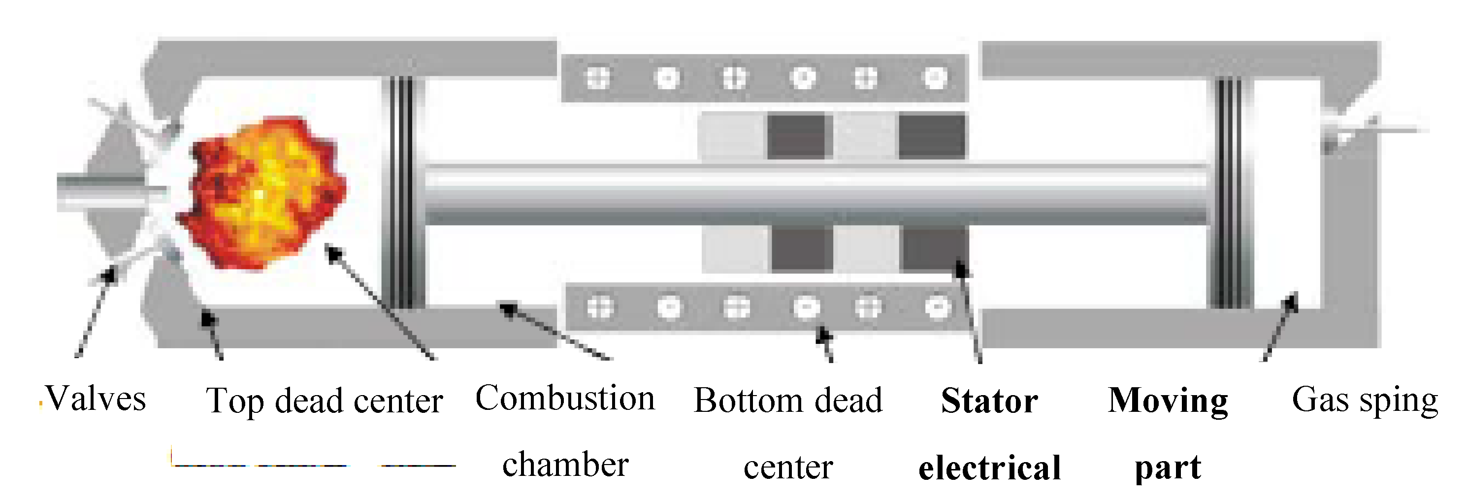


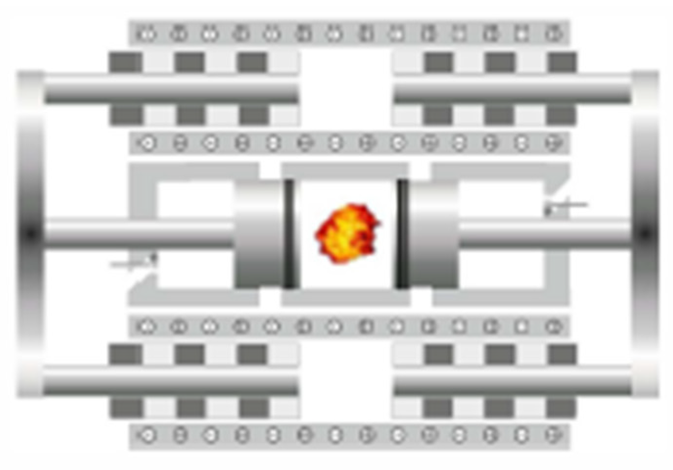

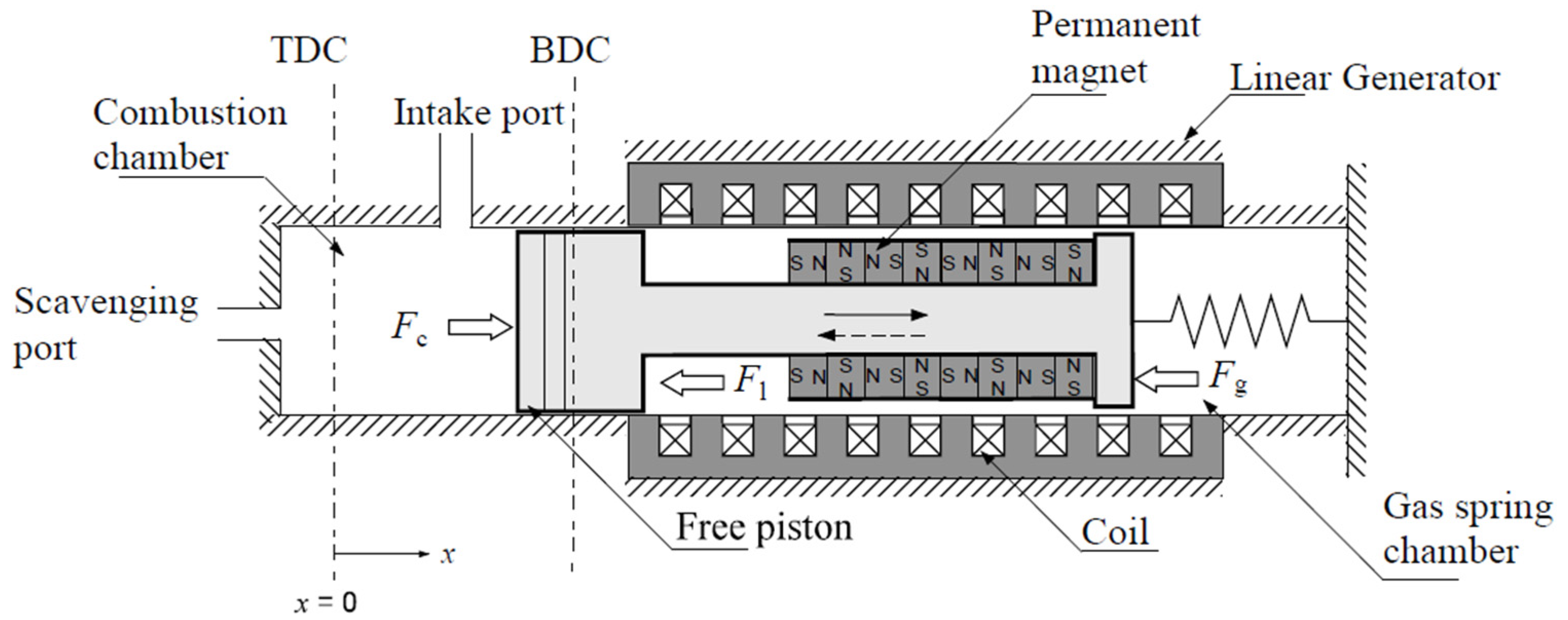
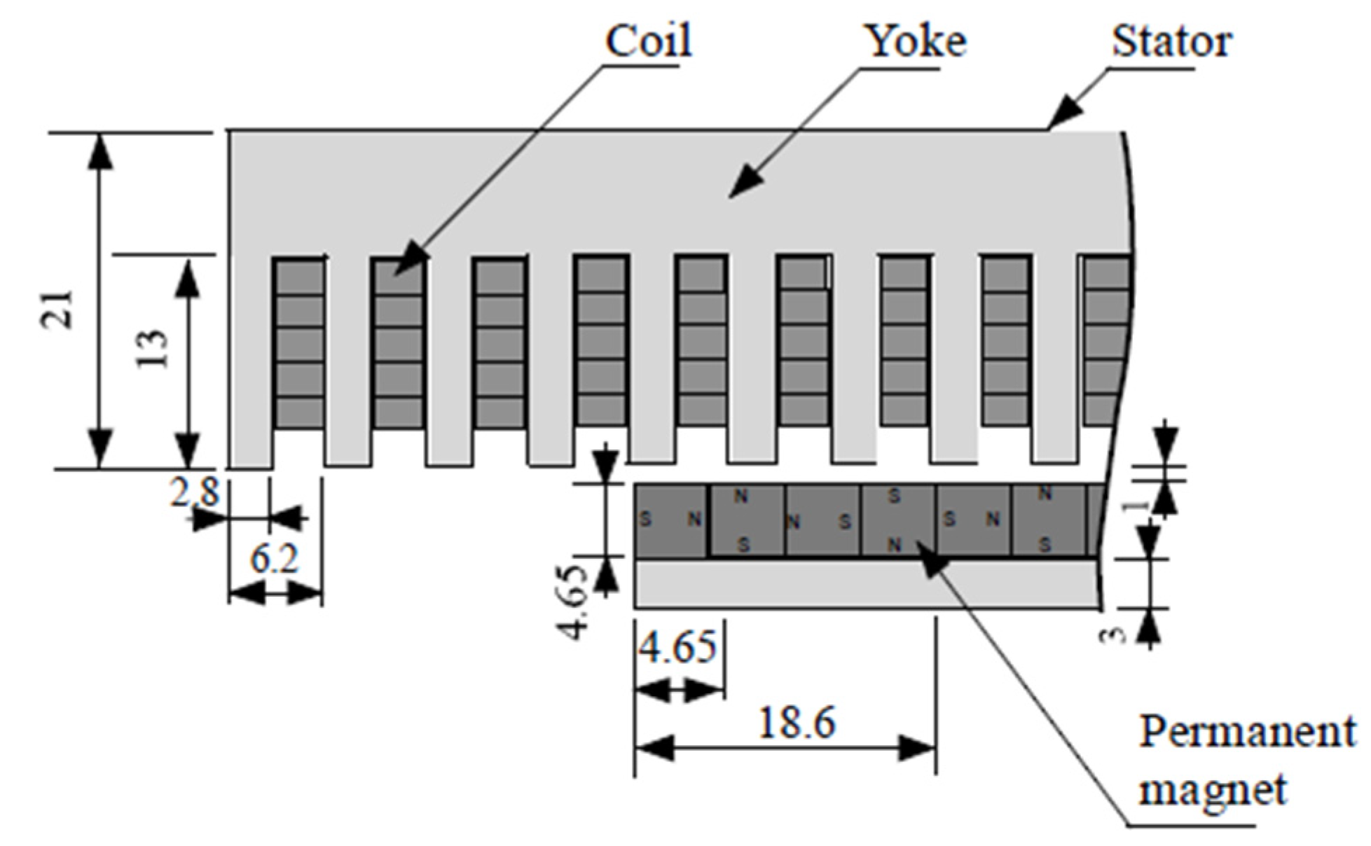
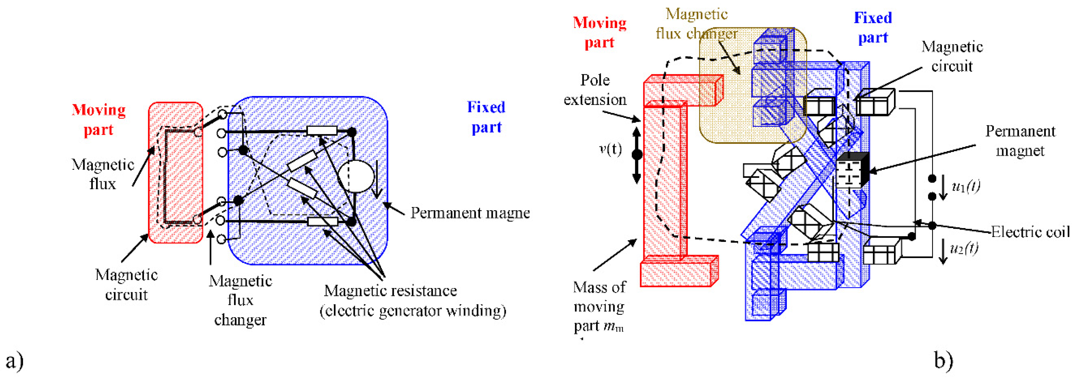
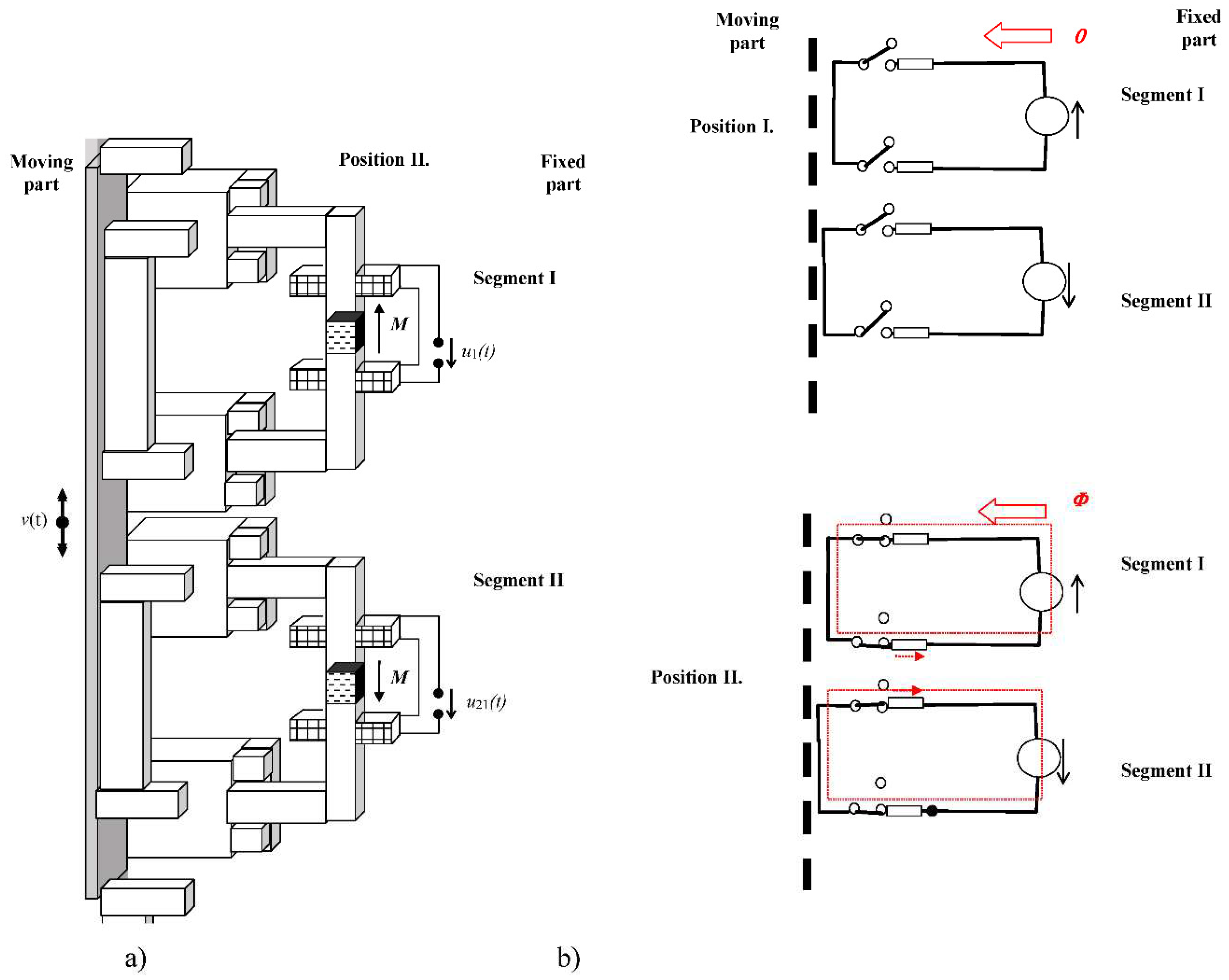
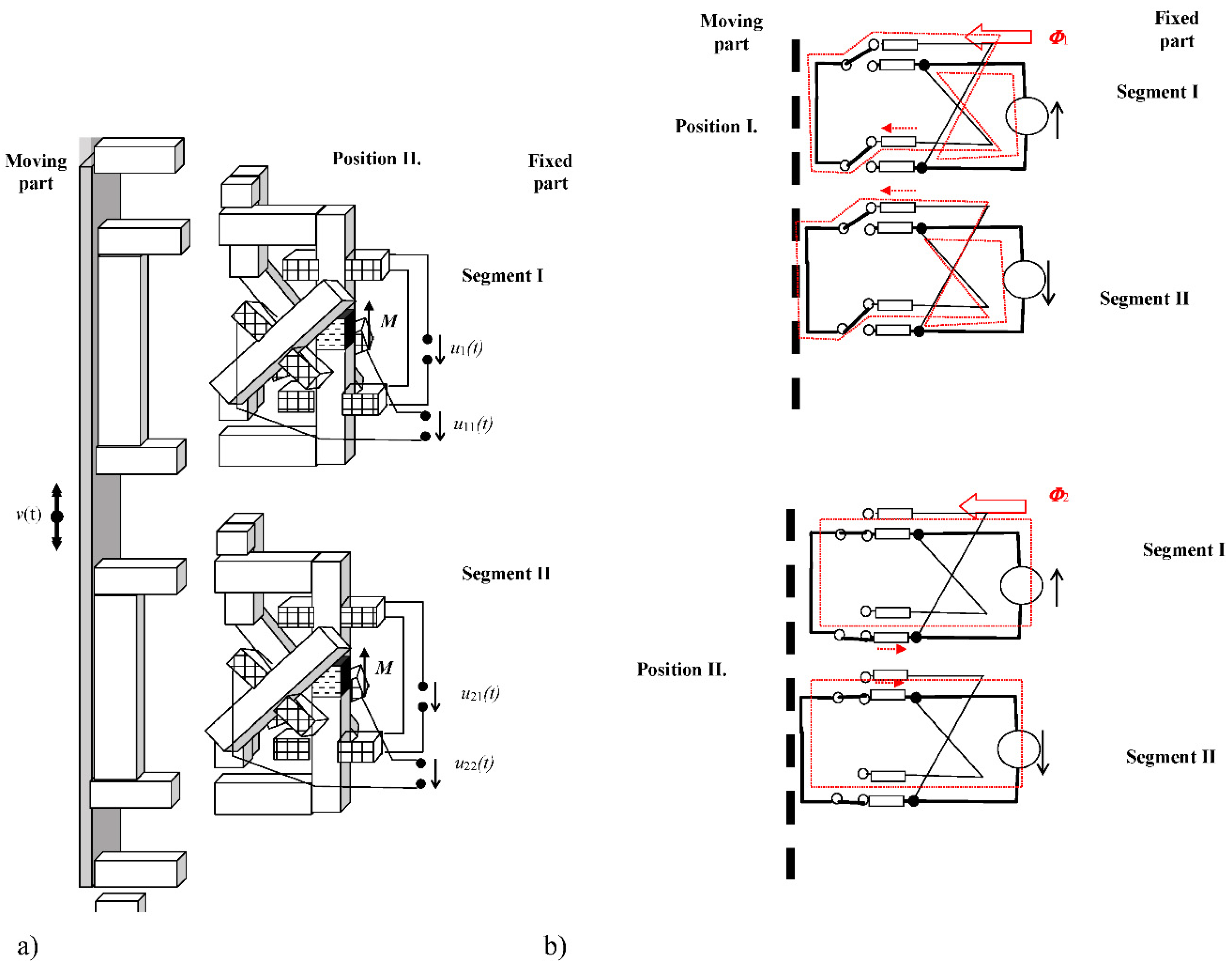


| Reference | Permanent Magnet type |
Generator Body Size x,y,z [m] |
Resonant Frequency fr [Hz] |
Amplitude mech. part A [m] | Output Power Pout [W] | Output Voltage Uout [V] | Load Resistance R [Ω] | Acceleration G, g = 9.81 [m/s] |
 [W/m3] [W/m3] |
| Beeby et al. [12], 2007 | − | 375 mm3 | 52 | − | 2 × 10⁻⁶ | 0.428 RMS | 4000 | 0.06 g | ≈6 |
| Zhu et al. [13], 2010 | FeNdB | 2000 mm3 | 67.6−98 | 0.6 × 10⁻³ | 61.6–156.6 × 10⁻⁶ | − | − | 0.06 g | ≈30−80 |
| Kulkarni et al. [11], 2008 | FeNdB | 3375 mm3 | 60−9840 | 1.5 × 10⁻³ | 0.6 × 10⁻⁶ | 0.025 | 52,700 | 0.398-4 g | ≈0.2 |
| Wang et al. [15], 2007 | FeNdB | 256 mm3 | 121.25 | 0.738 × 10⁻³ | - | 0.06 | - | 1.5 g | - |
| Lee et al. [17], 2012 | FeNdB | 1.4 × 10⁻⁴ m3 | 16 | − | 1.52 × 10⁻³ | 4.8 | 5460 | 0.2 g | ≈10 |
| Yang et al., [16], 2014. | − | 50,000 mm3 | 22−25 | 13.4 × 10⁻³ | 0.7−2.0 | 110 | 0.6 g | ≈270 | |
| Elvin et al., [14], 2011 | − | 15,000mm3 | 112 | − | 4 × 10⁻⁶ | 0.007 | 986 | - | ≈0.26 |
| MG I [2], 2006 | FeNdB | 90, 40, 30 mm | 20−35 | 50 × 10−6−400 × 10−6 | 70 × 10−3 | 4−60 (300) p-p | 7500 | 0.15−0.4 g | ≈650 |
| MG II [2], 2006 | FeNdB | 50, 27, 25 mm | 17−25 | 50 × 10−6−400 × 10−6 | 19.5 × 10⁻³ | 6−15 | 5000 | 0.1−0.7 g | ≈60 |
| MG III | FeNdB | 50, 25, 25 mm | 21−31.5 | 50 × 10−6−400 × 10-6 | 5.0 × 10⁻³ | 1.0−2.5 | 600 | 0.05−0.4 g | ≈15 |
| MG IV | FeNdB | 50, 35, 25 mm | 21−31.5 | 50 × 10−6−400 × 10−6 | 8.0 × 10⁻³ | 1.0−2.5 | 1200 | 0.05−0.4 g | ≈18 |
| *Lith. battery [19], 2018 | ≈40 × 106 | ||||||||
| *supercap [20], 2010 | ≈3−5 | ||||||||
| *fuel | ≈4 × 10⁹ | ||||||||
| *U235 | ≈9 × 10¹⁶ |
| Measurement HV | *type I | **type II | ***type III |
|---|---|---|---|
| U0[V] | 0,2 | 0,3 | 0,8 |
| Uz[V]@Z1=150W | 0,01 | 0,02 | 0,5 |
Disclaimer/Publisher’s Note: The statements, opinions and data contained in all publications are solely those of the individual author(s) and contributor(s) and not of MDPI and/or the editor(s). MDPI and/or the editor(s) disclaim responsibility for any injury to people or property resulting from any ideas, methods, instructions or products referred to in the content. |
© 2023 by the authors. Licensee MDPI, Basel, Switzerland. This article is an open access article distributed under the terms and conditions of the Creative Commons Attribution (CC BY) license (http://creativecommons.org/licenses/by/4.0/).


