1. Introduction
Wireless sensor networks (WSN) is a soaring frontier research hotspot in multi-subjects area [
1]. It can collaboratively monitor, sense and collect the various information of environments or monitored objects in real-time through various integrated micro-sensors, and transmits the perceived information to the user terminal by multi-hop relay through a random self-organized wireless communication network. WSN can realize the idea of "ubiquitous computing", and has become an integral part of the C4ISRT system (command, control, communication, computing, intelligence, surveillance, reconnaissance and targeting). Today, it is widely used in various areas of IoT/AI, such as: healthcare [
2], energy management [
3], smart transportation [
4], thermal comfort [
5] and energy load identification [
6].
The nodes of WSN are usually a miniature embedded system. Its advantages are small size, low cost, and easy to deploy, while the disadvantages are that its energy, storage space, computing power, and bandwidth are greatly limited. Most WSN are deployed in sparsely populated or human-inaccessible areas, and it is difficult to replace the batteries for the nodes. Therefore, the limited power energy is one of the most important constraints in the design of the whole WSN, which directly determines the life cycle and application life of the network. To extend the life cycle of WSN, there are two ways: power supply and energy saving. For this reason, many researchers at home and abroad have done a lot of work, such as: self-power supply technology for harvesting energy from nature[
7], wireless power technology[
8], node energy consumption problem[
9].
However, their proposed schemes lack comprehensiveness and exhibit poor performance. Additionally, certain schemes may be too computationally demanding to be implemented on sensor nodes that have limited resources. To prolong the life cycle of WSN, we have focused on three key areas for improvement: (1) Energy harvesting technology. We analyzed the current mechanisms and methods of energy harvesting technology, explored the utilization of solar energy and mechanical vibration energy to ensure a continuous and dependable power supply to the sensor nodes, and examined the voltage output characteristics of bistable piezoelectric cantilever in order to gain further insights. (2) Low-duty-cycle working mode. we proposed a neighbor discovery mechanism that utilizes a separation beacon, based on reply to ACK, to facilitate the identification of neighboring nodes. This mechanism operates at a certain duty cycle ratio, significantly reducing idle listening time and resulting in substantial energy savings. (3) Data fusion technology. we introduced a data fusion mechanism founded on integer wavelet transform. This mechanism effectively eliminates data redundancy caused by spatio-temporal correlation, and can reduce energy consumption associated with data transmission by the nodes.
2. Related Work
The energy management of nodes can increase the service cycle and reduce the cost of WSN. It involves two problems, namely, energy supply and energy consumption. The research progress at home and abroad is described below.
(1)
Energy harvesting technology. There are two main energy supply methods for the network nodes: wireless charging technology and energy harvesting technology. However, the wireless charging technology has limitations in terms of short charging distances and is not suitable for powering WSN deployed in remote areas [10-11]. Fortunately, the energy harvesting technology provides an ideal solution for meeting the energy demands of WSN [12]. Currently, there exist numerous well-developed energy harvesting technologies. Of all these technologies, solar energy harvesting stands out as the earliest and most advanced method. The solar harvester has the ability to generate milliwatts of energy per square centimeter, making it suitable for powering wireless sensor nodes. However, its performance is affected by environmental factors such as darkness and precipitation. On the other hand, vibration energy is readily abundant in the natural environment and has a high energy density, making it a perfect candidate for environmental energy harvesting technology [13]. Among the different types of vibration energy harvesting devices, piezoelectric devices have garnered considerable interest in recent years [14-15] This is primarily due to their exceptional attributes, such as high energy conversion efficiency, utilization of lightweight materials, simple yet robust structure, and seamless integration. Currently, the utilization of piezoelectric devices is predominantly based on the implementation of cantilever, cymbal, and cylindrical structures for energy harvesting. Among these structures, the cantilever structure has garnered considerable interest in both domestic and international research circles due to its straightforward implementation and resonance capabilities in low-frequency natural environments [16-17].
(2) Low duty cycle working mode. In this mode, the radio frequency (RF) of nodes will enter the active state that can send and receive data, and be closed and turned into the dormant state at other time to reduce energy consumption. At this point, the mutual discovery between adjacent nodes becomes the main problem. There are classical neighbor discovery protocols at home and abroad, include Disco, U-Connect, Hello, and Nihao [
18]. They focus on optimizing the scheduling period when the node works to find neighboring nodes to each other as quickly as possible with as few active time slots. Y Zhang et al. [
19] demonstrated that it is less likely to have a conflict at the beginning and end of the time slot, and proposed that the probability of conflict can be reduced by dynamically changing the time slot length and making random retreat. K Bian et al. [
20] proposed that beacon conflict can be reduced by controlling the length of slot time and the number of beacons. S Jin et al. [
21] proposed a mixed mode of send-receive-send and send-receive, and explored the relationship between the discovery performance and slot size on a specific hardware platform. Y Qiu et al. [
22] proposed an interactive mechanism by separating sending and reception of beacon. In this mechanism, nodes only send the beacon in the transmission time slot and receive the beacon in the listening time slot, which can reduce the probability of beacon conflict.
(3) Data fusion mechanism. Saeedi et al. [
23] demonstrated that the network is larger or the number of source nodes is more, the effect of saving energy is more significant by using data fusion technology. There are various classifications of data fusion from different perspectives. Based on the spanning tree, Wensheng Zhang et al. [
24] proposed the DCTC (dynamic convey tree-based collaboration) algorithm. The convergence nodes perform data fusion on the data of their sub-generating tree nodes. Hong Luo et al. [
25] proposed the MFST (minimum fusion steiner tree) algorithm for energy-efficient data collection in data fusion mode in WSN. Based on the spatiotemporal correlation, the TiNA model (temporal coherency aware in network aggregation) is proposed [
26]. Its basic idea is that the node sends the data only when the difference between the currently collected data and the last collected data is greater than the tolerance limit specified by a certain user. The spatial fusion model [
27] measures the correlation by the distance between nodes. Spatio-temporal fusion model [
28] is the development trend of data fusion research to eliminate spatio-temporal correlation. The LEACH protocol (low-energy adaptive clustering hierarchy) [
29] is a typical WSN routing protocol, which forms a hierarchical structure-based routing mechanism.
As presented above, the energy harvesting technology and energy saving mechanisms (include low duty cycle and data fusion) are the two main means to extend the service life of wireless sensor networks. However, in previous studies, they often focused on only one technology and did not comprehensively consider the problem of extended service life span of wireless sensor networks. Based on this case, we comprehensively used the technologies such as energy harvesting, neighbor discovery and data fusion to analyze the energy supply and energy consumption of nodes, and hoped to propose a new approach to achieve the reliable and efficient way to secure our energy in WSN.
3. Methods
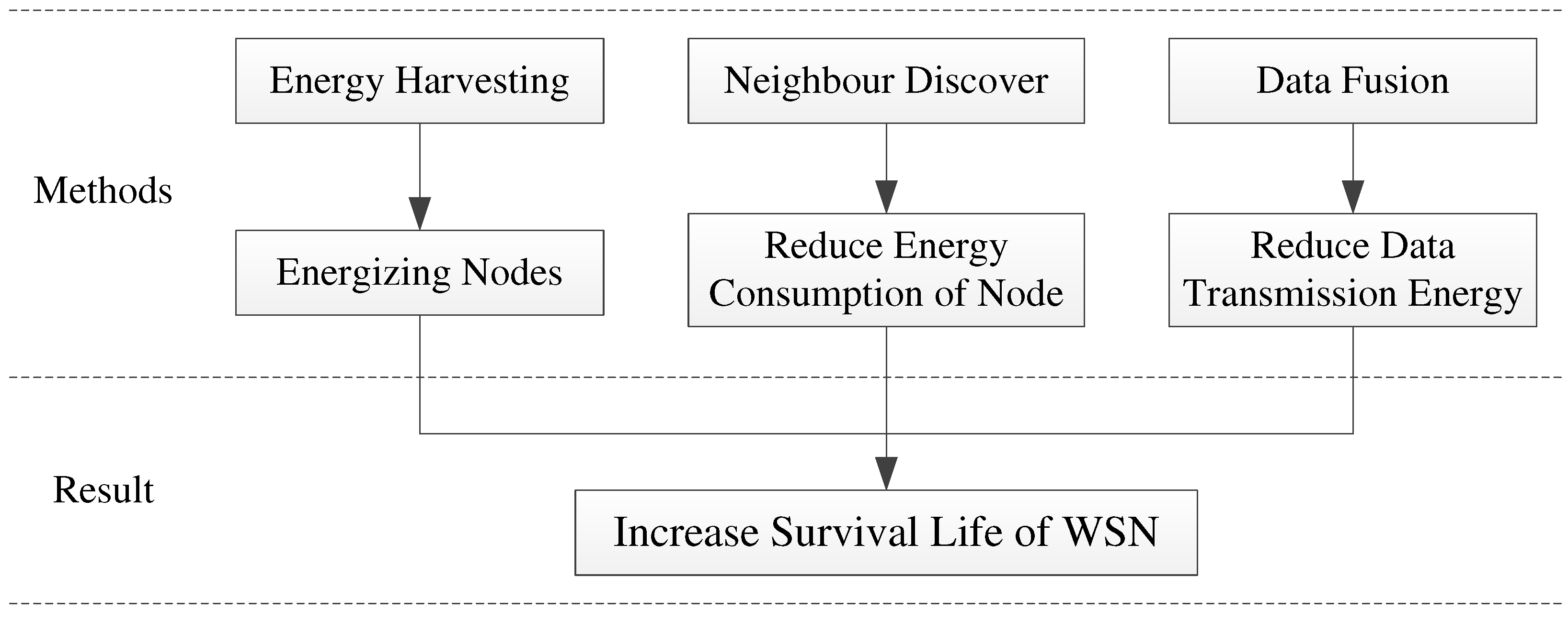
To enhance the energy efficiency and longevity of the network, we have implemented two strategies for the WSN, as illustrated in
Figure 1. Firstly, we employ energy harvesting technology to convert renewable sources like solar and wind energy into electrical energy, which effectively supplements the power supply of the nodes. Secondly, we utilize neighbor discovery technology to decrease the operational time of the nodes, along with data fusion technology to reduce the volume of data transmission. These measures are aimed at minimizing energy consumption and prolonging the network's usage period.
3.1. Energy Harvesting System
The battery is generally used to supply energy for nodes in WSN, but it is necessary that the battery limited energy storage is timely replaced and supplied to ensure the continuous normal operation of the node. In practical application, the real environment is often very complex, which brings great difficulties to lay the power wire or replace the battery for each node, and therefore, it largely limits the universality and flexibility of WSN applications. To solve this problem, we use the energy harvesting technology to realize the autonomous power supply of WSN.
At present, the sources of energy harvesting technology generally include solar energy, electromagnetic radiation energy, mechanical vibration energy and thermal energy. The solar harvesters can obtain several milliwatts of power per square centimeter, which can meet the application demand of wireless sensor nodes. However, the solar cells can convert energy output by the panel only if the light is sufficient, and a single solar energy cannot guarantee a sustainable and reliable power supply for nodes. The energy harvester based on mechanical vibration has been the attention of scholars at home and abroad, because the vibration energy is widely found in the natural environment. The main ways of vibration-to-electric energy conversion are as follows: piezoelectric, electromagnetic and electrostatic. Among them, the basic principle of piezoelectric vibration energy harvesting is: under the excitation of the external vibration source, the mechanical deformation of the piezoelectric material causes the movement of its internal electrons to generate electric energy. Piezoelectric has the advantages of simple conversion structure, fast response speed and high energy density, which is more and more favored by research institutions and high-tech enterprises. The piezoelectric power generation mechanism relies on the d31 and d33 effects of piezoelectric materials. Among them, the cantilever type piezoelectric generator utilizes the d31 effect, which demonstrates a remarkable power output [30-31]. Additionally, the cantilever structure is characterized by its simplicity, high flexibility, and ability to achieve a low natural frequency. Currently, numerous studies [32-34] have been conducted on the vibration generation of piezoelectric cantilever beams, with a primary focus on investigating the impact of piezoelectric structure, size, and parameters on power generation. Considering the cost and reliability of the energy harvesting system, this paper organically combines the piezoelectric technology and the solar technology to ensure the energy supply to the sensor nodes.
3.1.1. Overall Scheme
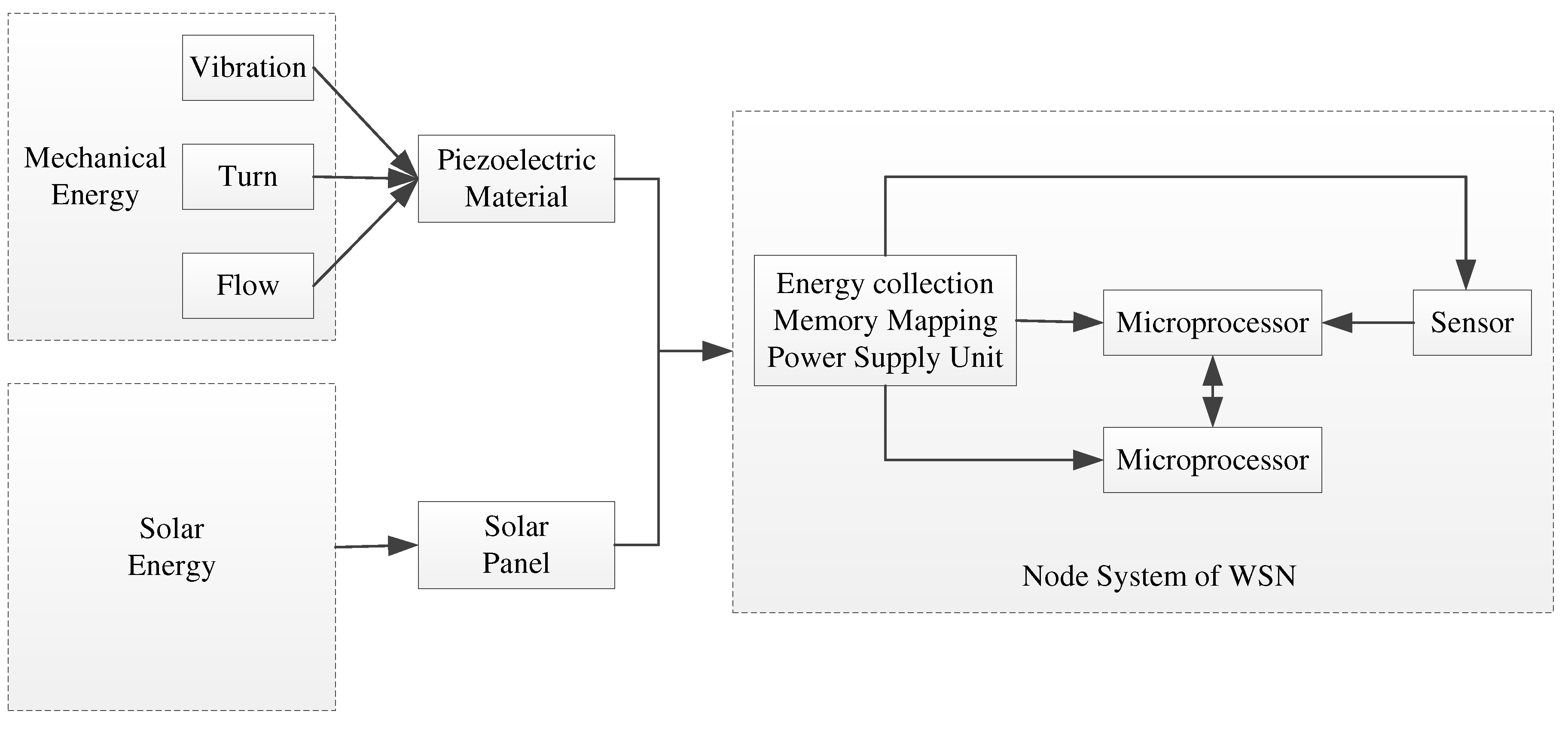
Energy harvesting technology can collect the ubiquitous energy such as thermal energy, solar energy, wind energy and electromagnetic energy into electrical energy through the appropriate power electronic equipment and the voltage conversion circuit. At present, there are many more developed energy harvesting technologies, and the main source of its energy is generally mechanical vibration energy, electromagnetic radiation energy, solar energy and heat energy and other energy. In order to realize the self-power supply demand of each sensor node in WSN, we use solar energy and mechanical energy as the energy source of energy harvesting technology to realize the conversion to electric energy. The framework diagram of node energy supply in WSN is as shown in Fig. 2.
3.1.2. Design of Power Supply Circuit
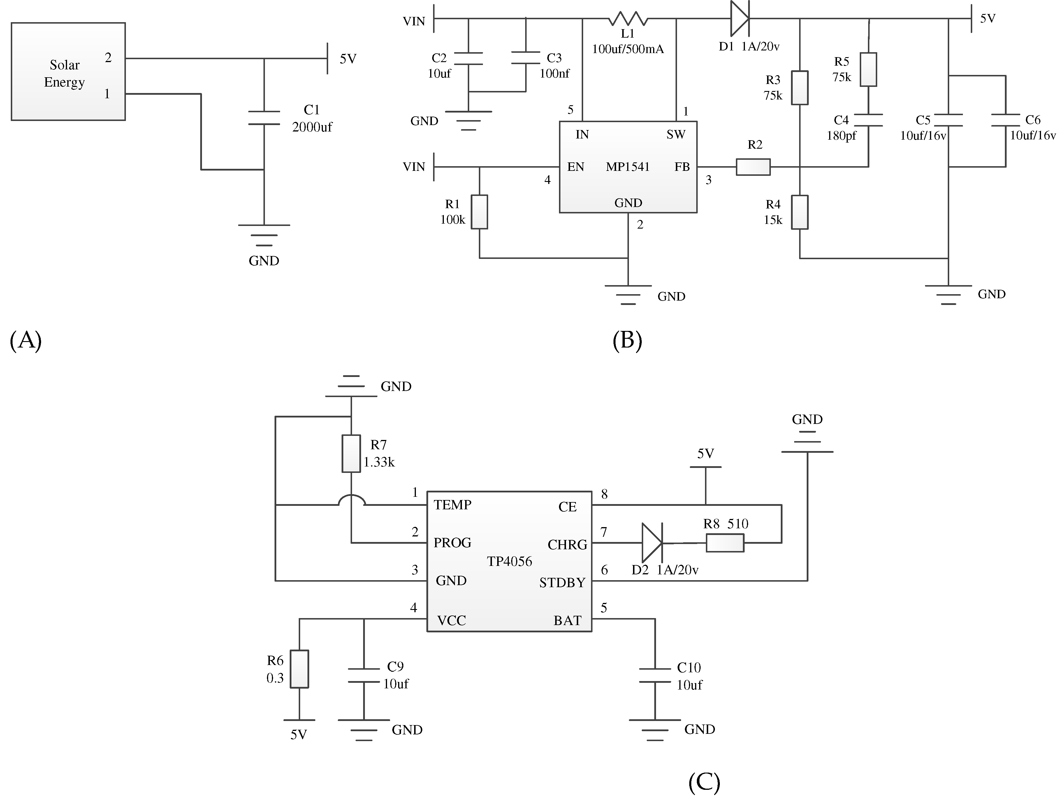
The power supply circuit is mainly divided into three parts. The first is the solar power generation circuit, as shown in Fig. 3(A). The solar panel can output about 5V DC voltage, and the large capacitance is used to maintain the stability of the voltage. The second is piezoelectric ceramic power generation circuit, as shown in Fig. 3(B). We use the MP1541 chip to design voltage boost conversion circuit with a fixed frequency and peak current mode. The third is electric energy storage circuit, as shown in Fig. 3(C). We use the TP4056 chip to design charging circuit completed the power supply to the lithium battery.
Figure 2.
Framework diagram of node energy supply in WSN.
Figure 2.
Framework diagram of node energy supply in WSN.
Figure 3.
Diagram of power supply module (A): solar power generation circuit and (B): piezoelectric ceramic power generation circuit and (C): electric energy storage circuit.
Figure 3.
Diagram of power supply module (A): solar power generation circuit and (B): piezoelectric ceramic power generation circuit and (C): electric energy storage circuit.
3.2. Neighbor Discovery Mechanism
3.2.1. Low Duty Cycle
In WSN, nodes must be in a listening state to receive the data from the neighbor node. However, nodes are in idle listening state for most of the time, and the time used for data transmission is often very short, while idle listening causes a lot of invalid energy consumption. Therefore, in many practical applications, nodes adopt low-power communication chips with alternating listening and hibernation modes. It can reduce the unnecessary energy consumption of nodes by replacing idle listening through dormancy.
Considering the application in practice, the low duty cycle mechanism is introduced into WSN. Where, duty cycle is the ratio of periodic dormancy to activity time, and low duty cycle is that duty cycle is not greater than 10%. When the node works in the duty cycle mode, the time will be divided into the time slot of the same size. At a certain number of time slots, the RF will enter the active state that can send and receive data, and the RF will be turned off and enter the dormant state after the time slot ends. The low duty cycle mechanism greatly extends the life cycle of the network and reduces the energy consumption caused by idle listening.
However, under the low duty cycle mechanism, nodes are in sleep state for most of the time. But, nodes are required to open RF as much as possible to communicate with other nodes in order to quickly complete the mutual discovery between nodes. Therefore, saving energy consumption and reducing the detection delay are contradictory, and it is very necessary to study the neighbor discovery problem in the low duty cycle wireless sensor networks.
3.2.2. Sending and Receiving Separation Beacon Mechanism Based on Reply to ACK
The neighbor discovery protocol focuses on optimizing the scheduling period when the node works, and it determines the frequency of active time-slot encounters between neighboring nodes. While the beacon mechanism determines the probability of achieving mutual discovery when neighbor nodes meet in an active time slots. At present, most of the studies focus on how to optimize the work scheduling cycle of nodes. There are few studies around the beacon mechanism. In fact, the beacon mechanism also plays a very important role in the discovery of neighbor nodes.
Most of the existing beacon mechanisms in WSN are used for sending and receiving beacons in a single time slot. The sending of the beacon will have a certain constraints on the variation range of the time slot size and the listening time in the time slot, which brings serious effects on the mutual discovery between nodes, especially when the time slot is small. Therefore, we will propose a sending and receiving separation beacon mechanism based on reply to ACK, which only listens to the beacon in the active time slot, and sends the beacon at the end of its previous time slot. In addition, the node immediately replies to ACK after receiving the beacon sent by the adjacent node.
The sending and receiving separation beacon mechanism based on reply ACK is as shown in Fig. 4. Where, nth Slot represents the nth time slot, and it is active. At this point, the node will turn on the RF at the end of the (n-1)th slot and transfer the RF from the launch completion state to the send beacon state. Then, the beacon is sent before the end of the (n-1)th slot and the RF is converted to the listening beacon state, and the node will only listen to the beacon in the active time slot. When node A meets node B in an active time slot, node A receives the beacon sent by node B, and it immediately enters the stage of replying to ACK after analysis and verification processing. The bi-directional discovery between nodes can be completed after node B successfully receives ACK.
Figure 4.
Time slot model of sending and receiving separation beacon mechanism based on reply ACK.
Figure 4.
Time slot model of sending and receiving separation beacon mechanism based on reply ACK.
Discovery probability is an important indicator to measure the performance of the discovery beacon mechanism of neighbor nodes. Improving the discovery probability between nodes can reduce the detection delay and realize the rapid discovery between nodes. When the response ACK mechanism is adopted, the bidirectional discovery can be completed by dynamically extending the time slot after realizing one-way discovery. The bidirectional discovery probability
Pd is:
where,
tslot is the time of an active time slot for a node.
tPR is the time that the node takes to send the synchronization packet.
tTX is the time interval between sending the beacon and listening the beacon.
3.3. Data Fusion Mechanism Based on Integer Wavelet Transform
Data fusion is a very important technology in WSN and is a research hotspot. This technology can process a large amount of raw data collected by sensor nodes in various networks through a certain algorithms, remove the redundant information, and transmit only a small number of meaningful processing results to the convergence node. The use of data fusion technology can greatly reduce the amount of data needed to be transmitted in WSN, reduce data conflicts, reduce network congestion, and thus effectively save energy costs, and prolong the life of the network.
In WSN, the perceptual data collected by nodes from the environment is a time-series data, as a strong time correlation and periodicity because of the short interval, while the data set generated by the whole network has a certain spatial correlation due to the close distance. For spatial correlation between data, integer wavelet transform can also be used to remove redundant parts.
3.3.1. Integer Wavelet Transform
Spatiotemporal data have strong linear features, which consists of multiple curves and is well-suited for applying the wavelet transform. After wavelet transformation, most of the energy of the data is stored in the low frequency component, and the detail information is stored in the high frequency component. It does well in removing the redundant information from the original data.
The integer wavelet transform is a new wavelet construction method, and has the following advantages: (1) It has only the integer shift and addition and subtraction operation, processes data quickly, has low hardware requirements, and is easy to implement. (2) It is completely reversible, which can perform both lossy coding and lossless coding. There are 12 commonly used integer wavelet filters, which have different computational complexity and compression performance. Among them, 5/3 wavelet has a small calculation amount and a good compression effect, which is often used to do lossless compression of spatiotemporal data [
35]. Its transformation formula is as follows:
Where, si,j is the j-th approximation of the k-level transformation decomposition, di,j is the j-th detail value of the k-level transformation decomposition, ⌊·⌋ means rounding down. In practice, we need to use symmetric periodic extension for boundary data.
3.3.2. Select Sink Node and Construct Hierarchical Structure
(1) Select Sink node
The Sink node undertakes a lot of operations of data processing and forwarding within the group. Often, the node with strong ability is selected as the Sink to complete the communication function of the group and extend the life cycle of network at the same time. When the Sink node is selected, three factors need to be considered: residual energy, link quality and degree. Therefore, we set a weight
w, and then the Sink is finally determined based on the calculated
w value. The calculation of
w can be defined as:
where,
Eiis the residual energy of the node
vi,
E0 is the initial energy of nodes,
Ejis the residual energy of the neighbor node,
Lij is the link quality between the node
vi and the neighbor node,
Lmax is the maximum value of link quality in the group,
Di is the degree of node
vi,
Da is the average of degrees of nodes in the group,
ɑ,
β,
γ is the adjust parameters, and satisfy:
ɑ +
β +
γ = 1.
(2) Construct hierarchical network structure
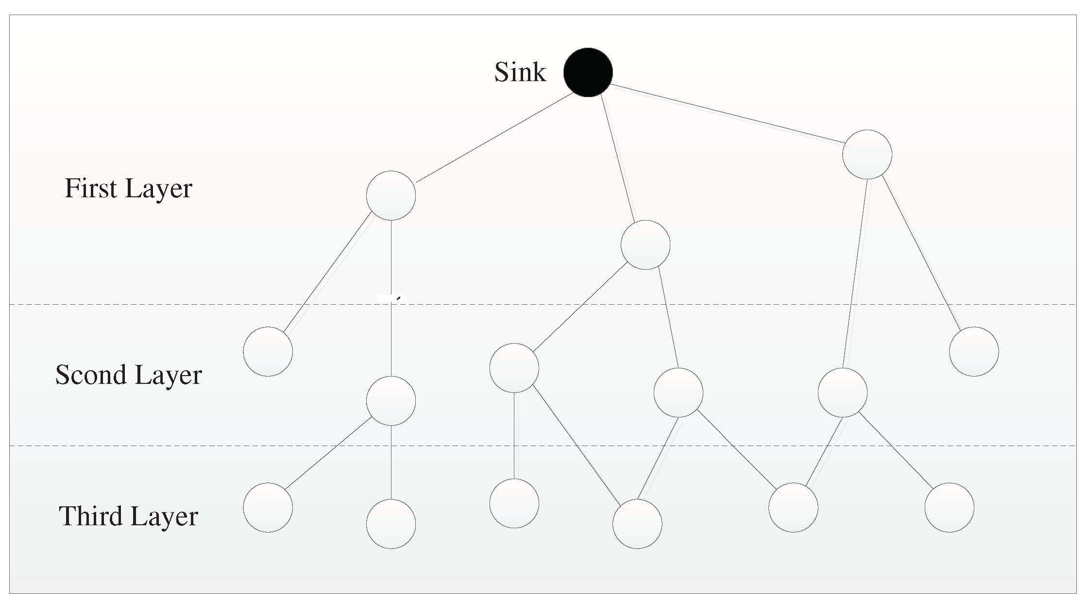
The nodes in the group transfer the data to the convergence nodes by a hop transmission, and then the convergence nodes should forward these data to the Sink node. To achieve this submission mode, it is required to build a hierarchical network structure.
Figure 5.
Diagram of hierarchical network structure in WSN.
Figure 5.
Diagram of hierarchical network structure in WSN.
As shown in Fig. 5, the white nodes are the ordinary nodes in the network, and they can be layered by the message flooding of Sink nodes. In this process, the Sink node broadcasts a request message to all adjacent nodes, and these nodes that have received the message need to set their layer value to 1 and continue to broadcast the message to the surrounding nodes. After receiving the message, the surrounding nodes should first check whether their layer value has been set. If not, their own layer value adds 1 on the basis of the broadcast layer value, that is, their layer value is 2. These nodes with level 2 continue to broadcast this message, and thus the third layer node will be formed, and then all nodes will finally have their own layer value.
3.3.3. Data Fusion Based on Integer Wavelet Transform
The data collected by a single node have strong temporal correlation due to the short interval, while the data generated by multiple nodes in the network have some spatial correlation due to their close distance. We used integer wavelet transform techniques to remove spatio-temporal dependent redundancy of these data.
(1) Time-dimensional data fusion of single node
The operation process of time-dimensional data fusion using integer wavelet transform is as follows: Step 1, Data preprocessing. It mainly carries out data cleaning and data integer transformation on the raw data collected by the nodes. Step 2, Integer wavelet transform. The time dimensional data series is decomposed into low and high frequency coefficients based on integer wavelet transform. Step 3, Coefficients quantification. The wavelet coefficients were quantified by using scalar quantification techniques. Step 4, Encoding. The wavelet coefficients were encoded using the encoding algorithm, such as deflate algorithm.
(2) Spatial-dimensional data fusion of nodes
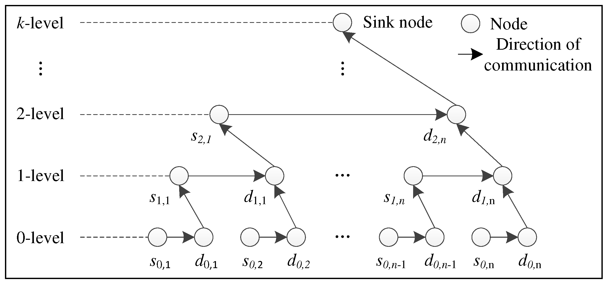
The operation process of spatial-dimensional data fusion using integer wavelet transform is as follows: Step 1, Integer wavelet transform of data for the underlying node. the nodes at the underlying of network are divided into the even nodes s0,i and the odd nodes d0,i in the order, and then the even node s0,1 transmits its data to the adjacent odd node d0,1 and calculate the integer wavelet coefficients s1,1 and d1,1. Correspondingly, we can be obtained all the coefficients of the 1-level wavelet decomposition (d1,1, d1,2, …, d1,n) and (s1,1, s1,2, …, s1,n) . Step 2, Integer wavelet transform of data for the convergence node. The underlying odd nodes send the low frequency coefficient (s1,1, s1,2, …, s1,n) to the convergence nodes of the upper layer and form a new data sequences. By repeating the Step 1 operation, we can be obtained the 2-level wavelet transform coefficients (d2,1, d2,2, …, d2,n) and (s2,1, s2,2, …, s2,n). Step 3, Integer wavelet transform of data for the Sink node. The Sink node obtains the k-level wavelet transform coefficients (dk,1, dk,2, …, dk,n) and (sk,1, sk,2, …, sk,n). The diagram of spatial-dimensional data fusion of nodes is as shown in Fig. 6.
Figure 6.
Diagram of spatial-dimensional data fusion of nodes
Figure 6.
Diagram of spatial-dimensional data fusion of nodes
4. Simulations and Results
4.1. Energy Harvesting System
4.1.1. Performance of the Solar Energy Harvester
The test data of the energy harvesting system that we have designed are shown in
Table 1, and it records the test data of this system on a sunny day in Yiyang, Hunan Province. The elements of the test mainly include: voltage regulator circuit input voltage, node power supply voltage and node power supply current. The test results show that the energy harvesting system is stable in power supply to the node, maintains about 3.3 V, less than 1.3% in voltage deviation, and it has high accuracy, strong robustness, and can provide reliable energy guarantee for WSN.
4.1.2. Performance of the Bistable Piezoelectric Cantilever Oscillator
(1) Simpleandharmonic incentive
In this experiment, we examinedthe power generation performance of a bistable piezoelectric cantilever oscillator composed of two magnets under simple harmonicincentive, with varying magnetization strength and load resistance. In Figure 7(A), the voltage amplitude frequency curve is compared for different magnetization intensities. The system's voltage amplitude solution exhibits jumps as the excitation frequency changes. Furthermore, an increase in the nonlinear term coefficient results in a rightward shift of the curve, widening the response band of large motion and increasing the amplitude. Figure 7(B) displays the power generated at different impedances. It is noteworthy that the jump phenomenon's corresponding excitation frequency in the system's amplitude and frequency curve remains unchanged regardless of the resistance value. In the system, there is an issue with resistance matching. Specifically, the resistance value R=30k needs to be addressed and optimized.
Figure 7.
The power generation performance of a bistable piezoelectric cantilever oscillator (A): Amplitude-frequency curves at different magnetization strengths and (B): Output power at different impedance levels
Figure 7.
The power generation performance of a bistable piezoelectric cantilever oscillator (A): Amplitude-frequency curves at different magnetization strengths and (B): Output power at different impedance levels
(2) Random incentive
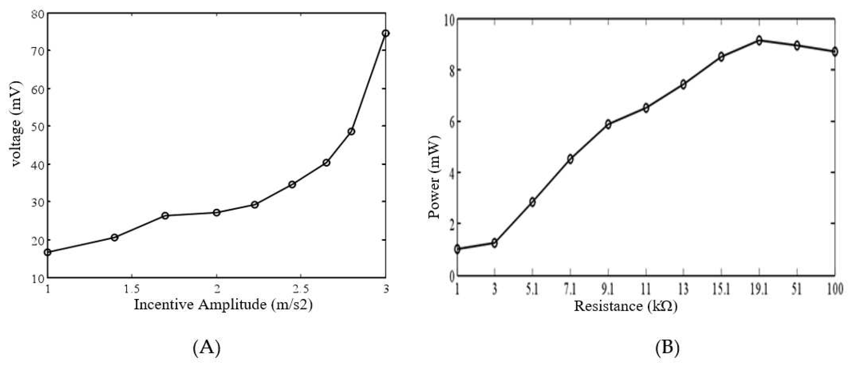
In this experiment, we examined the impact of various incentive strengths and load resistances on the response of a bistable piezoelectric cantilever subjected to random incentive. The excitation strength was set to 0.01~0.09 G2/Hz and the load resistance was 1k. As shown in Figure 8(A), the output voltage of the system increases proportionally with the excitation strength. The incentive strength is 0.06 G2/Hz, and Figure 8(B) is the average power curve when the impedance changes. The figure clearly demonstrates that at a resistance of 19.1 k, the output power reaches its peak. This signifies that matching the impedance maximizes the output power of the system when subjected to random excitation.
Figure 8.
The power generation performance of a bistable piezoelectric cantilever oscillator (A): Average voltage curves for different excitation intensities and (B): Average power curves at the different impedances
Figure 8.
The power generation performance of a bistable piezoelectric cantilever oscillator (A): Average voltage curves for different excitation intensities and (B): Average power curves at the different impedances
4.2. Neighbor Discovery
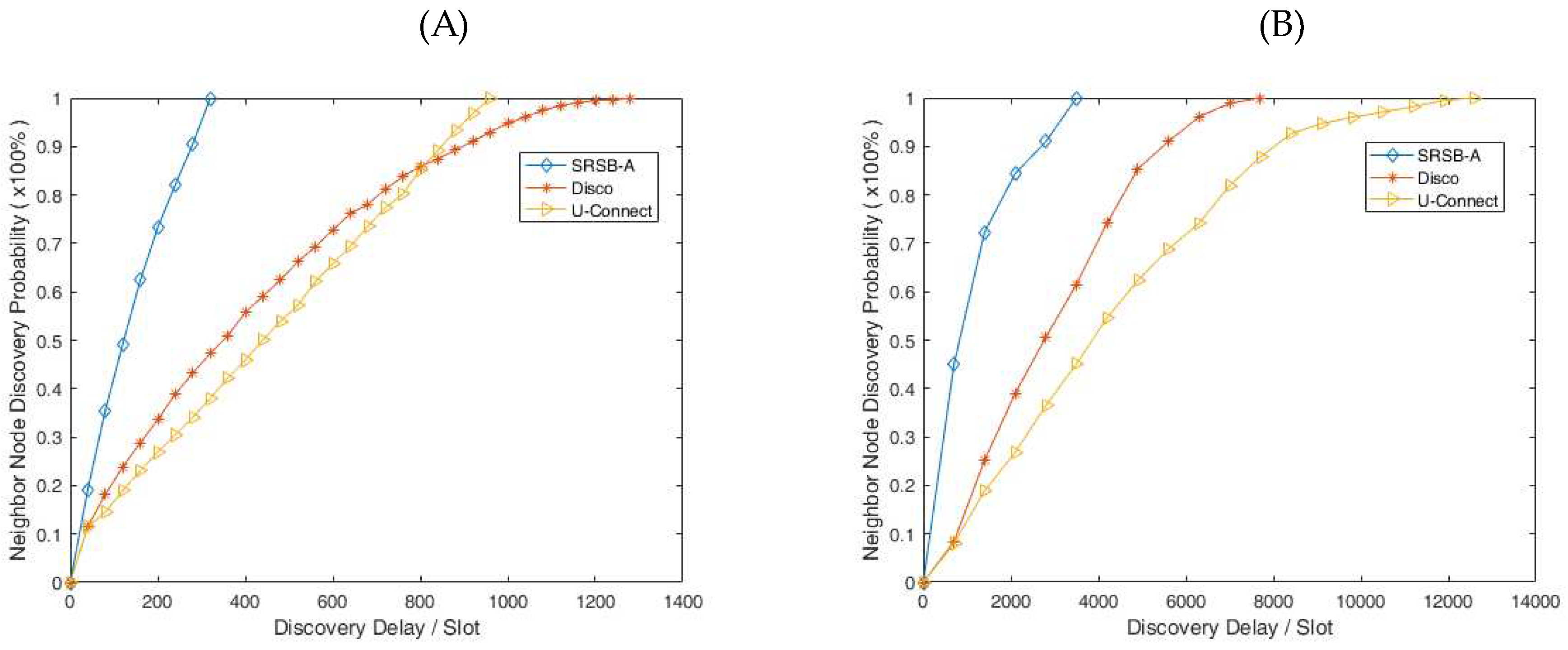
In this experiment, the sending and receiving separation beacon mechanism based on reply to ACK (SRSB-A) is tested on the operating system Tiny OS 2.0 and the sensor node Telos B. To evaluate the performance of SRSB-A, we compare it with protocols such as Disco, U-Connect, etc. Fig. 9(A) shows the contrast experiment with a 5% duty cycle in asynchronous symmetric scenes. The results show that the node in the SRSB-A can be successfully found by its neighbor node within 320 time slot, and in the worst discovery delay, The SRSB-A reduced 66.67% and 75% over Disco and U-connect, respectively. As shown in Fig. 9(B), in the contrast experiment with a 5% duty cycle in asynchronous asymmetric scenes, the node in the SRSB-A can successfully discover neighbor nodes within 3600 time slots. In the worst discovery delay, The SRSB-A reduced 53.37% and 71.27% over Disco and U-connect, respectively. Based on the above analysis, it can be considered that the SRSB-A has a good performance.
4.3. Data Fusion
In this experiment, the experimental data are from the Tropical Atmospheric Ocean Project (TAO). Since 1984, the project has deployed about 100 sensors at different depths in 71 mooring in the tropical Pacific to collect the temperature of seawater in the region. We use these data for the lossless compression testing, and the test computer configuration is as follows: Processor: Intel (R) Core (TM) i5-6500 CPU @ 3.20GHz, memory: 16GB, operating system: 64-bit operating system. The test results are shown in
Table 2. Compressed by using integer wavelet transform, the spatial and temporal data can obtain a average compression rate of 5.42. Compared with other lossless compression algorithms Huffman, LZSS, LZW and WinRAR, the integer wavelet transform has a higher compression ratio, more than 1 times.
Figure 9.
Contrast experiment for neighbor node discovery (A): Symmetry scene and (B): Asymmetric scene
Figure 9.
Contrast experiment for neighbor node discovery (A): Symmetry scene and (B): Asymmetric scene
On the other hand, we took the raw data of 96 sensors from the data set of TAO to carry out the three-level integer wavelet transform, and then analyze the data storage of nodes. After integer wavelet transform, the 1-level wavelet coefficients is (
s1,1,
s1,2, …,
s1,52) and (
d1,1,
d1,2, …,
d1,52), the 2-level wavelet coefficients is (
s2,1,
s2,2, …,
s2,30) and (
d2,1,
d2,2, …,
d2,30), and the 3-level wavelet coefficients is (
s3,1,
s3,2, …,
s3,19) and (
d3,1,
d3,2, …,
d3,19). Among these data, the data (
d1,1,
d1,2, …,
d1,52) is stored in the bottom node, the data (
d2,1,
d2,2, …,
d2,30) is stored in the convergence node, and the data (
d3,1,
d3,2, …,
d3,19) is stored in the Sink node. Compared with the traditional communication mode, the amount of data stored in the integer wavelet transform is much smaller, as shown as
Table 3, which indicates that the integer wavelet transform has certain advantages in reducing the amount of communication data and transmission energy.
5. Discussion
For WSN with limited energy, the energy management of node is still one of the most important factors restricting their large-scale and long-term deployment and application.
(1) Energy harvesting technology
It is an effective power supply technology for nodes to harvest the energy produced by the surrounding environment. In the energy storage module, we use capacitors to store energy, which can avoid the problems of node failure caused by frequent charging and discharge of batteries, but the capacitors have the shortcomings of less storage energy and large leakage current. In addition, the energy collection, storage and management circuit will also consume electricity, so that the utilization rate of energy is not high, and only when the solar panel voltage is higher than the capacitor voltage, the solar energy is used by the system.
(2) Neighbor discovery mechanism
Low duty cycle can reduce the idle listening time and save a lot of energy. However, the current mechanism of neighbor beacon discovery based on low duty cycle is too idealistic in analyzing the discovery probability and beacon conflict between nodes, which is quite different from the actual working situation between nodes. In addition, the factors such as the size of time slot and the number of beacon in the active time slot will have an important impact on the performance of the neighbor discovery. In this paper, our time slot model is closer to the actual working process of sensor nodes, and the sending and receiving separation beacon mechanism based on reply to ACK can effectively reduce the beacon conflict. In addition, the low-duty cycle mechanism can result in longer detection delays. In general, longer detection delays can miss some communication opportunities, which are not acceptable. However, shorter detection delays can consume more energy, thus it is required a balance between the detection delay and energy expenditure in the application of WSN.
(3) Data fusion mechanism based on integer wavelet transform
Data fusion can greatly reduce the amount of data in the network, which is conducive to reducing the energy expenditure of nodes by data transmission. Lossless data compression based on the integer wavelet transform can reach a compression ratio of 4-19 times, which can better remove the spatial and temporal correlation of the data. In addition, the distributed preservation of multi-resolution data can solve the limitation of the storage space of nodes and improve the disaster recovery capacity of the network. However, the integer wavelet transform has some requirements on the computational power of the nodes.
6. Conclusions
In this paper, we have discussed the problem of node energy management in wireless sensor networks. In order to extend the service life of the network, we took three measures. Firstly, the solar panels and pressure ceramics are used to harvest solar energy and vibrating mechanical energy in nature to supply energy to the sensor nodes. Secondly, the neighbor discovery mechanism based on low duty cycle is studied to reduce the idle listening energy consumption of nodes. Finally, the data fusion mechanism based on the integer wavelet transform is studied to reduce the transmission data energy consumption of the node. The experimental results show that these measures are effective in reducing the energy consumption of nodes and extending the life span of network. However, there are numerous challenges and opportunities that still exist in the field of energy management in WSN. Further research should focus on developing more efficient energy collection and conversion technologies, establishing dynamic models of bistable piezoelectric generation systems, and exploring the response characteristics of the latter under random excitation. Additionally, optimizing the design of bistable piezoelectric generation systems is crucial. Furthermore, the low power technology of nodes needs to be further studied in order to design and optimize the energy management system for the entire wireless sensor network. This includes node energy management, energy distribution strategies, and energy balance technologies. By effectively scheduling the energy usage of the nodes, the stable operation and long lifespan of the entire network can be ensured.
Acknowledgments
This work is supported by the National Natural Science Foundation of China under grant (61672540, 61379057 and 61309001), the Natural Science Foundation of Hunan Province under grant (2017JJ2057).
References
- Nurlan, Z.; Zhukabayeva, T.; Othman, M.; et al. Wireless Sensor Network as a Mesh: Vision and Challenges [J]. IEEE Access 2021, 10, 46–67. [Google Scholar] [CrossRef]
- Ko, J.; Lu, C.; Ma, S.B.; et al. Wireless Sensor Networks for Healthcare [C]. Proc. IEEE 2010, 98, 1947–1960. [Google Scholar] [CrossRef]
- Tekler, Z.D.; Low, R.; Yuen, C.; Blessing, L. Plug-Mate: An IoT-based occupancy-driven plug load management system in smart buildings [J]. Build. Environ. 2022, 223, 109472. [Google Scholar] [CrossRef]
- Low, R.; Cheah, L.; You, L. Commercial Vehicle Activity Prediction With Imbalanced Class Distribution Using a Hybrid Sampling and Gradient Boosting Approach [C]. IEEE Trans. Intell. Transp. Syst. 2021, 22, 1401–1410. [Google Scholar] [CrossRef]
- Tekler, Z.D.; Lei, Y.; Peng, Y.; et al. A hybrid active learning framework for personal thermal comfort models[J]. Build. Environ. 2023, 234, 110148. [Google Scholar] [CrossRef]
- Tekler, Z.D.; Low, R.; Zhou, Y.; et al. Near-real-time plug load identification using low-frequency power data in office spaces: Experiments and applications [J]. Appl. Energy 2020, 275, 15391. [Google Scholar] [CrossRef]
- Sam, M.; Mahmoud, S.; Arash, D. Microwave wireless power transfer system using a dual- dielectric resonator oscillator[J]. AEUE-Int. J. Electron. Commun. 2023, 170, 154836. [Google Scholar]
- Martha, G.; Lukas, Z.; Christian, D.; et al. Self-powered elementary hybrid magnetoelectric sensor[J]. Nano Energy 2023, 115, 108720. [Google Scholar]
- Ilam, P.P.V.; et al. A hybrid ANFIS reptile optimization algorithm for energy-efficient inter-cluster routing in internet of things-enabled wireless sensor networks [J]. Peer--Peer Netw. Appl. 2023, 16, 1049–1068. [Google Scholar]
- Lu, X.; Wang, P.; Niyato, D.; et al. Wireless Charging Technologies: Fundamentals, Standards, and Network Applications [J]. IEEE Commun. Surv. Tutor. 2017, 18, 1413–1452. [Google Scholar] [CrossRef]
- Ren, J.; Hu, J.; Zhang, D.; et al. Rf energy harvesting and transfer in cognitive radio sensor networks: Opportunities and challenges [J]. IEEE Commun. Mag. 2018, 56, 104–110. [Google Scholar] [CrossRef]
- Ma, T.; Jia, S.; Ding, Y.; et al. Research on characteristics of piezoelectric vibration energy harvester of trapezoidal cantilever beam[J]. Instrum. Tech. Sens. 2021, 11, 43–47. [Google Scholar]
- Yang, J.; Zhao, X.; Zhou, X. Correction of Lumped-parameter Model for Piezoelectric Energy Harvesters with Variable Cross-section Cantilever Beams [J]. Noise Vib. Control 2020, 40, 42–46. [Google Scholar]
- Zou, H.; Wang, Z.; Song, J. Piezoelect ric Energy Harvesting Based on Nozzle - resonator System[J]. Sci. Technol. Vis. 2018, 7, 30–33. [Google Scholar]
- Sun, X.; Feng, W.; Zhang, Y. Study on the vibration power generation of piezoelectric ceramic composites[J]. Mach. Des. Manuf. Eng. 2019, 48, 88–92. [Google Scholar]
- Wang, S. Wake and energy harvesting based on the piezoelectric cantilever beam model in fluid; Zhejiang University: Hangzhou, China, 2014. [Google Scholar]
- Pradeesh, E.L. Effect of placement of piezoelectric material and proof mass on the performance of piezoelectric energy harvester [J]. Mech. Syst. Signal Process. 2019, 130, 664–676. [Google Scholar] [CrossRef]
- Qiu, Y.; Li, S.; Xu, X.; et al. Talk more listen less: Energy-efficient neighbor discovery in wireless sensor networks [C]. IEEE INFOCOM 2016-The 35th Annual IEEE International Conference on Computer Communications. IEEE, 2016; pp. 1–9.
- Zhang, Y. ; Bian K; Chen, L.; et al. Dynamic slot-length control for reducing neighbor discovery latency in wireless sensor networks [C]. GLOBECOM, 2017. [Google Scholar]
- Bian, K.; Zhang, Y.; Qia, P.; et al. Fine-grained collision mitigation control for neighbor discovery in wireless sensor networks [C]. 2017 IEEE/CIC International Conference on Communications in China (ICCC). IEEE, 2017; pp. 1–6.
- Jin, S.; Meng, X.; Wong, D.L.K.; et al. Improving neighbor discovery by operating at the quantum scale [C]. 2018 IEEE 15th International Conference on Mobile Ad Hoc and Sensor Systems (MASS). IEEE, 2018; pp. 202–210.
- Galluzzi, V.; Herman, T. Survey: Discovery in wireless sensor networks [J]. Int. J. Distrib. Sens. Netw. 2012, 8, 271860. [Google Scholar] [CrossRef]
- Saeedi, I.D.I.; Al-Qurabat, A.K.M. A systematic review of data aggregation techniques in wireless sensor networks [J]. J. Phys. Conf. Ser. 2021, 1818, 012194. [Google Scholar] [CrossRef]
- Zhang, W.; Cao, G. DCTC: Dynamic convoy tree-based collaboration for target tracking in sensor networks [J]. IEEE Trans. Wirel. Commun. 2004, 3, 1689–1701. [Google Scholar] [CrossRef]
- Luo, H.; Liu, Y.; Sajal, K.D. Routing correlated data with fusion cost in wireless sensor networks [J]. IEEE Trans. Mob. Comput. 2006, 5, 1620–1632. [Google Scholar]
- Sharaf, M.A.; Beaver, J.; Labrinidis, A.; et al. TiNA: A scheme for temporal coherency aware in network aggregation [C]. In The 3rd ACM International Workshop on Data Engineering for Wireless and Mobile Access; ACM Press: San Diego, CA, USA, 2003; pp. 69–76. [Google Scholar]
- Vuran, M.C.; Akan, O.B.; Akyildiz, I.F. Spatio-temporal correlation: Theory and applications for wireless sensor networks [J]. Comput. Netw. 2004, 45, 245–259. [Google Scholar] [CrossRef]
- Das, S.N.; Misra, S.; Wolfinger, B.E.; et al. Temporal-Correlation-Aware Dynamic Self- Management of Wireless Sensor Networks [J]. IEEE Trans. Ind. Inform. 2016, 12, 2127–2138. [Google Scholar] [CrossRef]
- Kandukuri, S.; Murad, N.; Lorion, R.; et al. Energy-Efficient Data Aggregation Techniques for Exploiting Spatio-Temporal Correlations in Wireless Sensor Networks [C]. In Wireless Telecommunications Symposium; IEEE: London, UK, 2016; pp. 1–6. [Google Scholar]
- Du, X. Micro piezoelectric power generator driven by ambient vibration [D]. Dalian University of Technology: Dalian, China, 2008. [Google Scholar]
- He, X.; Du, Z.; Zhao, X.; et al. Modeling and experimental verification for cantilevered piezoelectric vibration energy harvester [J]. Opt. Precis. Eng. 2011, 19, 1771–1778. [Google Scholar]
- Johnson, T.J.; Charnegie, D.; Clark, W.W.; et al. Energy harvesting from mechanical vibrations using piezoelectric cantilever beams [J]. Int. Soc. Opt. Eng. 2006, 6169, 61690D–12. [Google Scholar]
- Roundy, S.; Wright, P.K. A piezoelectric vibration based generator for wireless electronic[J]. Smart Mater. Struct. 2004, 13, 1131–1142. [Google Scholar] [CrossRef]
- Erturk, A.; Inman, D.J. On Mechanical Modeling of Cantilevered Piezoelectric Vibration Energy Harvesters [J]. J. Intell. Mater. Syst. Struct. 2008, 19, 1311–1325. [Google Scholar] [CrossRef]
- Guttorp, P.; Fuentes, M.; Sampson, P. Using Transforms to Analyze Space-Time Processes [M]. Stat. Methods Spatio-Temporal Syst.
|
Disclaimer/Publisher’s Note: The statements, opinions and data contained in all publications are solely those of the individual author(s) and contributor(s) and not of MDPI and/or the editor(s). MDPI and/or the editor(s) disclaim responsibility for any injury to people or property resulting from any ideas, methods, instructions or products referred to in the content. |
© 2023 by the authors. Licensee MDPI, Basel, Switzerland. This article is an open access article distributed under the terms and conditions of the Creative Commons Attribution (CC BY) license (http://creativecommons.org/licenses/by/4.0/).
