1. Introduction
The two-layer railway track model is widely used by other researchers to approximate several phenomena. Here it will be used to identify the set of parameters under which it exhibits irregular behavior, i.e., behavior that is not expected.
In recent decades, a considerable amount of research has been presented in this area, proving that it is an area of great interest and still very active thanks to the current trend of decarbonization, which require shifting road transport to rail. With this in mind, it is not possible to cover all relevant research in this section. Therefore, emphasis will be placed on similar solution techniques, avoiding finite and boundary element methods in this review.
To classify published works, the separation can be done according to structure: finite or infinite; or according to moving objects: moving force(s) or moving inertial object(s) like mass(es) or oscillator(s) or even simplified vehicle models. After that, the structure can be further divided into continuous 2D or 3D, or discrete, which usually consists of several layers. Further separation can distinguish fully linear or non-linear behavior.
When building a literature review, it is customary to start with Frýba's monograph [
1], which includes several cases mentioned in the previous paragraph. The moving force problem is generally much simpler, fully analytical solutions for infinite structures are given in [2-3]. The critical velocity is also determined, but in such structures with massless foundations, waves cannot propagate in the foundation, so the conclusions are unrealistic. With the base mass included, the results are more realistic [4-6].
Pioneering works on instability of moving inertial objects include [7-8] for finite beams and several moving masses and [
9] for infinite. Furthermore, the subject of single moving mass is described in detail in [10-11], where the instability is determined using the D-decomposition method. Several moving inertial objects on finite structures have been recently analyzed in [12-14]. Other works about infinite structures are also implementing the D-decomposition method together with the dynamic Green´s function [15-18] or integral transforms [19-20]. It is commonly assumed that the mass is in permanent contact with the beam, [19-20], however, in some works a contact spring is introduced, [15-18]. The critical velocity of the moving force is then usually not analyzed. A connection with the critical velocity and different approach to identifying instability by tracing the instability lines is presented in [21-22]. This approach is also suitable for the problem of two moving proximate masses, where a strong dynamic interaction can significantly alter the onset of instability. It can also derive the conditions under which the results can be superposed and identify cases where the dynamic interaction induces instability at a velocity lower than the lowest critical velocity of the moving force. The mentioned approach can be readily extended to moving oscillators.
Recent works deal with more complicated moving objects or foundation, [23-25]. Further extensions going to the large deflections are considered in [
26]. The change in stiffness of the Winkler foundation introduced with a smooth variation is analyzed in [27-28]. A moving force is applied in [
27], while a moving oscillator in [
28]. A comparison of possible methods for solving similar problems is presented in [
29]. When inhomogeneity is considered, the moving element method, successfully applied in [30-33], or the moving window, [
34], should also be mentioned, because they are efficient in dealing with such situations. In [
33] a computationally efficient and accurate numerical method for the dynamic response of a maglev train passing on an "infinitely" long multi-span bridge is proposed. The results are validated against test cases from the literature. A novel model for the dynamic interaction of the beam with its foundation is introduced in [
35]. It is shown that the Winkler and Pasternak moduli are not constant but time-dependent because they are influenced by the beam–foundation interaction. Therefore, they are determined as a part of the solution so as the mass that is dynamically activated in the foundation.
The two-layer model of the railway track is quite popular and was used to achieve several objectives, like e.g. in [36-37]. The three-layer model is more realistic and its applicability to represent full finite element models is dealt with in [
38] where also the question of the critical velocity of the moving force is briefly discussed. Among other recent works on layered models, [
39] can be mentioned. A very long finite three-layer model is considered in [
40]. The modal expansion method is applied to a reduced model to increase computational efficiency. A control volume is used to reduce the computational domain and the structure is traversed by a multi-body model of the vehicle.
In this paper, the two-layer model is analyzed from a different point of view. The goal is to establish the range of parameters leading to irregular behavior, where by “irregular” it is meant “different than expected”. In
Section 2, the model is introduced, and these irregular situations are described in detail. Furthermore, the range of allowable parameters is identified in
Section 3. After that, three sections are devoted to three topics where irregularity may occur. Finally, some conclusions are drawn in
Section 7.
2. The Model: Governing Equations and Irregular Situations
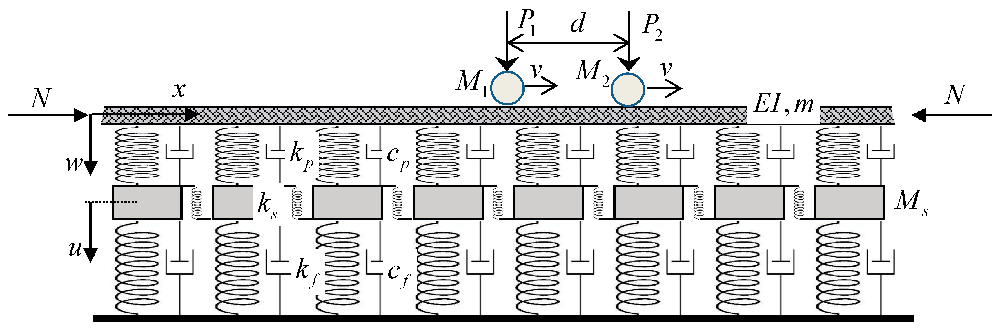
The track is modelled as an infinite Euler-Bernoulli beam standing for the rail, supported by spring-damper elements representing the rail pads,
and
, point masses modelling the sleeper half-masses
and supported further by spring-damper elements representing the vertical stiffness and damping of all other layers,
and
, that is the ballast, sub-ballast and foundation and other layers that might be placed below the sleepers. The rail may be subjected to an axial force
. The model is shown in
Figure 1.
The equations of motion in fixed coordinates where
is the spatial coordinate and
is the time, of the model depicted in
Figure 1 are
where, in addition to the parameters defined previously,
and
are bending stiffness and mass per unit length of the beam,
and
are the unknown vertical displacement fields of the beam and discrete masses, respectively, and
means the load. Derivatives are denoted by the respective variables in subscripts preceded by a comma. The load is given by
where
and
are the moving forces,
and
the moving masses,
is the velocity and
is the distance between the moving masses. Without affecting generality too much, all parameters are assumed to be distributed to simplify the solution. In
Figure 1 there is also a shear component
because the model should have some shear stiffness. Placing it between sleepers is not very realistic, but this is immaterial for the analysis.
In the following, an active point (AP) will be used to spatially locate a moving object on a beam, which will be either force or mass with force. The critical velocity (CV) will be used for the critical velocity of a moving constant force. In this sense it is a resonance effect because in the undamped scenario if the force is moving at its critical velocity, then there is no steady-state solution as it tends to infinity. CV indicates the separation between two distinct types of beam shape. Up to the lowest CV, approaching the lowest CV from below, the maximum deflection of the steady-state solution is reached at the AP. The minimum deflections are significantly lower than the maximum. There is no solution for CV and for velocities higher than CV there is zero deflection at AP and equal values for maxima and minima across the full beam. Similar properties can be found at higher CVs, in particular the most characteristic identification is preserved as a jump to zero deflection at the AP when crossing the CV.
Since the model has two layers, it is expected to have two CVs. By analyzing the equations, one or three resonances are found to exist. When there are three, then the arrangement finds that the mean value is the so-called false critical velocity (FCV), [v], which means that there is resonance, no steady-state solution, but the CV properties are not met, and there is also no connection to instability. The regular case is therefore the case with three resonances and the irregular case with only one, where the lowest CV must be replaced by the so-called pseudocritical velocity (PCV).
To access the instability conditions, either for one or two moving masses, instability lines (IL) will be traced in the moving mass-velocity plane. This approach is simpler than the D-decomposition method used by other authors. It simply means looking for the real mass induced frequency (MIF) that solves the characteristic equation in the damped case, since the real MIF always marks the separation between the stable and unstable regions.
In the case of a single moving mass, instability never occurs in the subcritical velocity range, but in the case of only one resonance, the PCV must play the role of a lower CV. Only two IL branches are expected to exist, tending to infinite moving mass near CV and zero mass for infinite velocity. The ILs for lower damping are below those for higher damping and do not cross. Moreover, asymptotically, the branches approach CVs better from the left than from the right. Irregular cases are characterized by a situation where the IL cross the higher CV. In such a case, there are usually more than only two branches and the additional ones can also form closed curves.
Unfortunately, for the two moving masses, the CVs do not provide any reasonable indication. The ILs generally cross both CVs, and there is an infinite number of IL branches whose asymptotes are not linked to the CVs. An irregular situation is thus identified as one where instability occurs due to dynamic interaction in a subcritical range of velocities. However, since the lower CV or PCV are always crossed, the condition must be defined differently. Crossover can occur for unrealistically high moving mass and this value will not be lower in the subcritical range. In such a case, it can be called regular behavior, because as for one moving mass with realistic value, the instability will always occur in the supercritical velocity region. The irregular situation will thus be such that after crossing the lower CV, the IL will decrease to realistic masses, which will push the instability into the subcritical range of velocities, unlike the single moving mass case where this can never happen.
It should be noted that IL cannot terminate suddenly, a detailed analysis has shown that there is always a continuation until it is closed or reaches an asymptote. The asymptotes are of three different kinds: (i) they tend to infinite mass because the real MIF tends to zero; (ii) they tend to infinite mass because the other terms tend to zero (this can be seen by the fact that as IF changes smoothly, the mass increases infinitely and suddenly jumps to infinite negative values); (iii) they tend to zero mass with increasing velocity.
3. Range of Allowable Values
The following discussion is provided to define the range of allowable values. As for the rail, the range of possible values is quite narrow, basically there are two guide sets of values for the 54E1 and 60E1 rails, determining the limits on
and
. More variability can be attributed to other data. They are listed in
Table 1 and correspond to the values given in [41-43].
The range of allowable parameters is defined with respect to their dimensionless counterpart, for which a reference Winkler beam is selected. As moving coordinates will be used, firstly the dimensionless moving spatial coordinate is introduced as
The other values are related to the reference Winkler beam by
where for simplicity designations are kept, but all values (except for
) are assumed as longitudinally distributed.
The decisive parameters are thus
and
. Assuming that the sleepers are spaced from 0.545 m [
44] to 0.6 m, which is typical on European railways, this identifies a relatively narrow interval for one parameter,
, but gives a very large variability for the other parameter,
.
There is little data on shear stiffness, so it will be set to zero in most examples. Similarly, the normal force when acting in compression will make the model softer, when acting in tension it makes the model stiffer, but since this is not the main concern, it will also be set to zero in most examples. Regarding the viscous damping coefficients, very different values can be found in the literature, so it was decided to directly vary the dimensionless parameters.
4. Critical Velocity of a Constant Moving Force
To determine the critical velocity of the moving force, Eq. (1)-(3) are first switched to a moving coordinate and changed to a dimensionless form. After removing the time-dependent terms not required for the steady-state regime, they read as
Where, besides parameters specified in Eqs. (4)-(6),
Next, the Fourier transform is applied. In transferred space, it is more convenient to write the equations in matrix form, which makes it easier to present the analytical solution
where
and
,
and
represent
,
and
in the Fourier space. Since the CVs should be determined without damping, expressions (13) and (14) can be further simplified.
To analytically determine the critical velocity, it is necessary to find at least one real double
-root of the determinant of system (11). This means finding a real solution to a system of two equations, where the first is the determinant and the second is its derivative with respect to
. The determinant can be written as a cubic polynomial with real coefficients for
and the second equation as a quadratic polynomial with real coefficients for
In order to express directly
, Eq. (16), multiplied by
, should be subtracted from Eq. (15) multiplied by 2. Then
which is simplified when
to
Thus, finding the real double -root is an easy task using predefined root-finding procedures in symbolic software such as Maple. Eq (17) or (18) are substituted into Eq. (16), which can for the given data and be solved for valid and consequently and .
To identify the irregular case means to identify the case where there will not be three resonances, but only one. Let us present this analysis for the simpler case of
. Then after substituting Eq. (18) into Eq. (16), a cubic equation is obtained for
. Its discriminant is simplified to
The irregular case occurs when expression (19) is negative, which means that there is only one real root for
. Expression (19) is fourth order polynomial for
and third order for
. Its analytical solution for
as a function of
to identify the separation between three and one resonances is given by
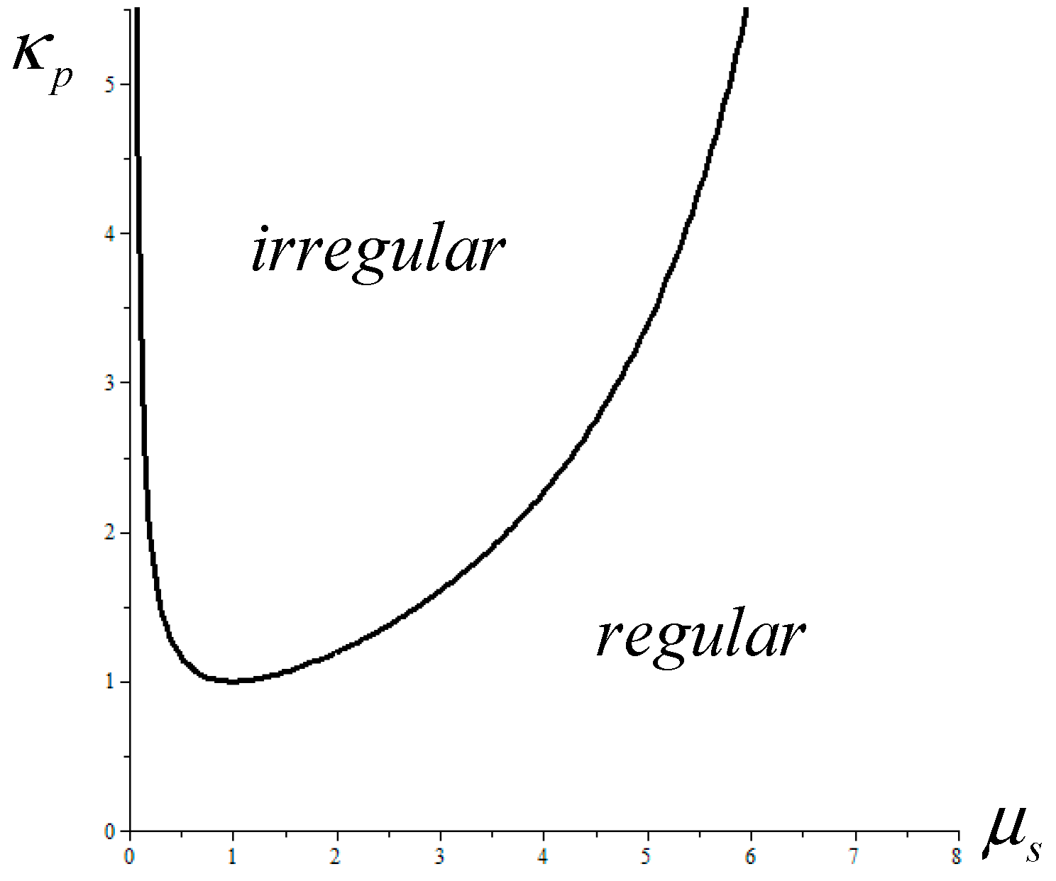
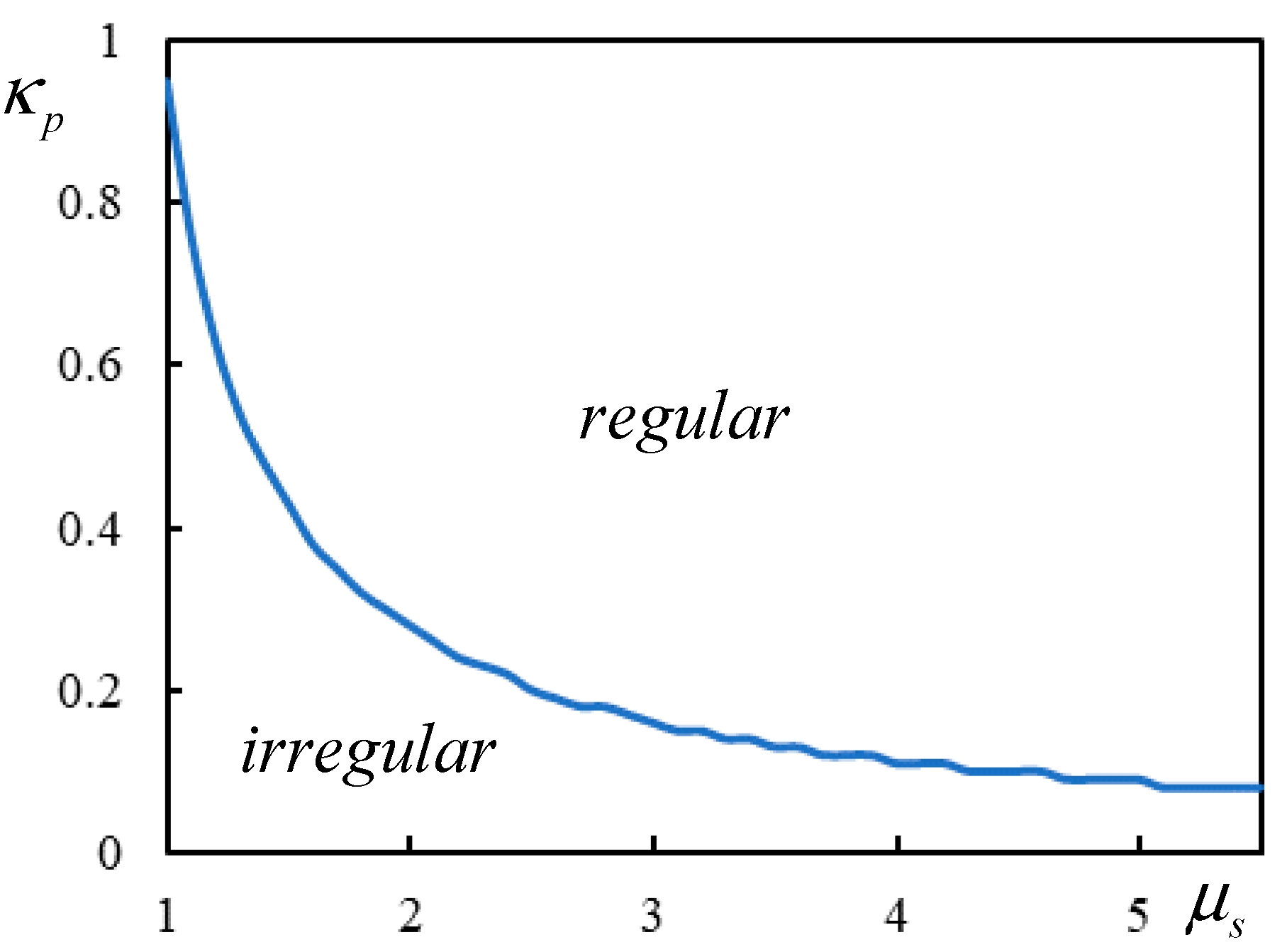
The separation of regions with three and only one resonance is shown in
Figure 2, where irregular stands for single resonance, regular for three resonances and cases falling on the boundary have, in fact, two resonances because one of the three resonances is doubled.
The curve in
Figure 2 is obtained by plotting
until
and then by
for larger
. It has an asymptotic tendency to
, but this is already outside the allowable value of
. It can be observed that
there is always an open interval of
for which there is only one CV. For
, there is only a double root
leading to no such interval. And so, one of the three resonances is doubled. The same happens when the selection
-
lies on the curve indicated in
Figure 2. In these cases, the CV properties are decisive, the FCV is suppressed, and the case can be considered as regular.
Two cases are chosen as an example for the regular situation:
,
and for the irregular one:
,
.
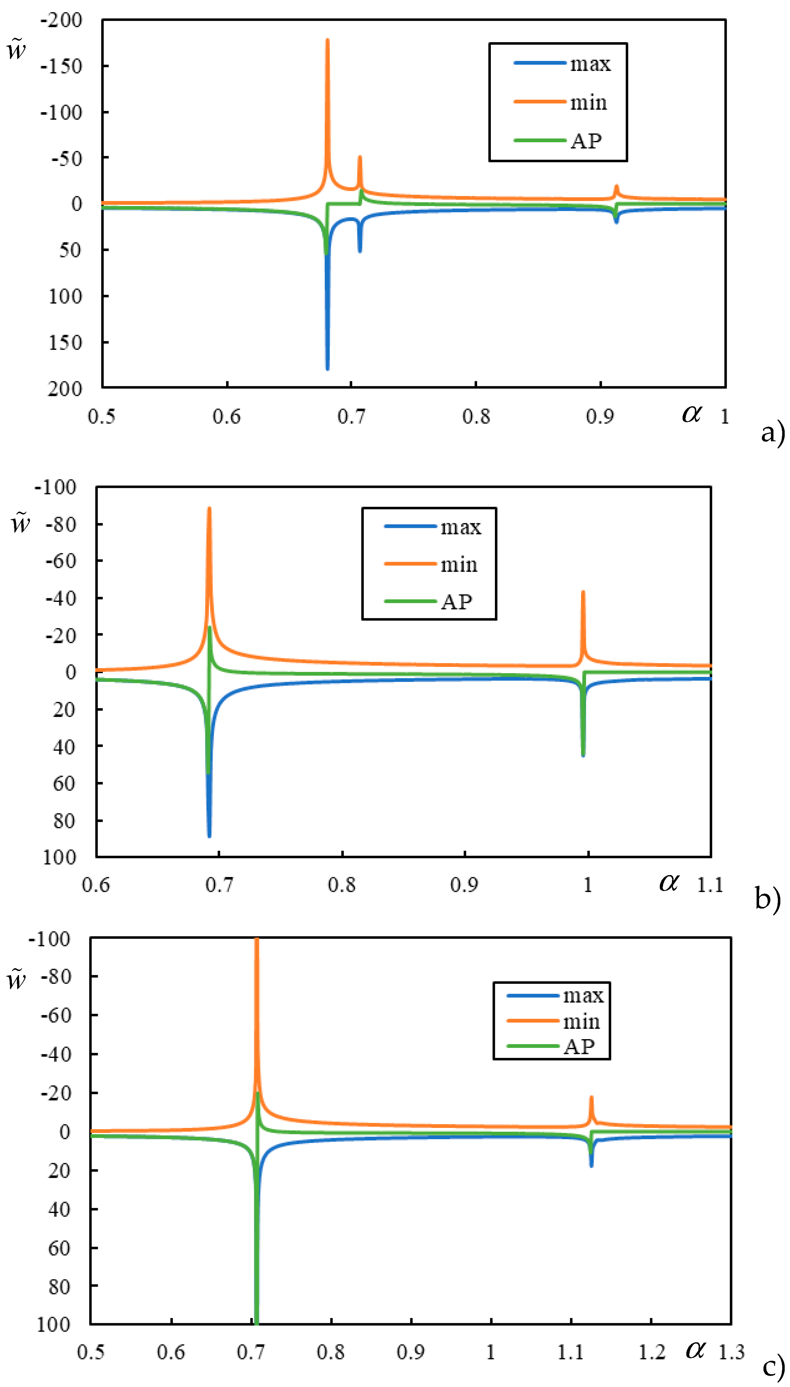
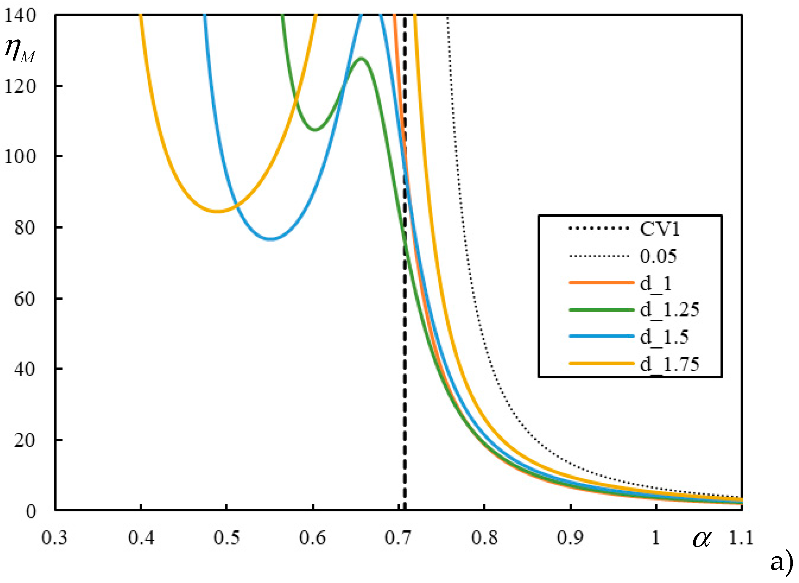
Figure 3 shows the results of the parametric analysis for the validation of the CVs. For better clarity, the scale does not start at
. In the regular case,
Figure 3a), it can be seen that the analytically determined values for the resonances: 0.681; 0.707 and 0.913 indicate CV, FCV and CV as predicted. In the irregular case,
Figure 3b), it is observed that the only analytically determined value of 0.996 is the higher CV and the lower CV is replaced by the PCV with value of 0.692.
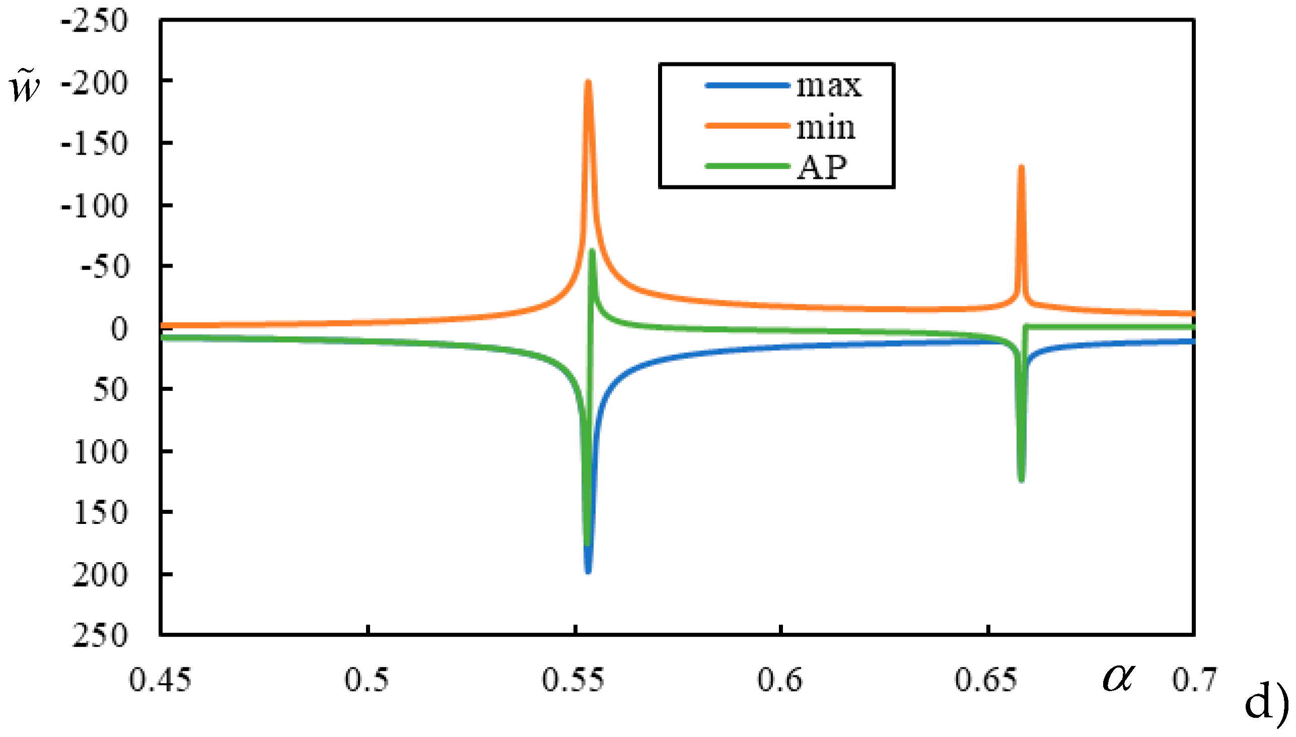
Other cases also shown in
Figure 3 concern the situations at the boundary of the domain shown in
Figure 2, i.e., when one of the roots is double.
Figure 3c) is for
and
which corresponds to the case where the interval of irregular cases is collapsed to a single value, proving that the CV is suppressed by the FCV (both equal to 0.707) and the case is irregular with a unique CV of 1.125. The same happens in the case in
Figure 3d) for
and
, which correspond to the lower end of the irregular case interval, which also proves that the CV is suppressed by the FCV (both equal to 0.553) and the case is irregular with a unique CV of 0.658.
This analysis is consistent with correspondence with finite beams according to [
45]. As explained in [
39], CV corresponds to local minima in the resonant velocity plot, FCV to a local maximum, and the double root to the inflection point.
In conclusion, it can be said that these irregular cases only mean that the first peak in the displacements is not found by solving the resonances and the PCV must be determined by parametric analysis. This is important for two reasons, firstly, CV does not provide relevant information about the lowest velocity where there is excessive vibration, secondly, when it comes to instability, PCV plays the role of a lower CV and therefore must be known to draw correct conclusions on the instability of moving inertial objects. In addition, PCV can be well-pronounced like in
Figure 3b), or not. Additionally, PCV may be well pronounced as in
Figure 3b) or not. When it is barely visible, extreme values are not always reached in the same
, and PCV determination is therefore ambiguous.
Additionally, it can be remarked that a very good estimate of the lower CV is provided by extension of the classical formula by considering stiffnesses in series and summing the masses, i.e., by
which is valid for higher
, approximately for
. This condition in fact means that for these values
is practically independent on
and thus
can also be used, which is actually exactly valid for
and any value of
, except for irregular case with
, when this value is FCV.
5. Instability of One Moving Mass
To solve the problem of instability of a single moving mass, the previously omitted time dependent terms must be included back, thus, Eqs. (7)-(8) are now given by
In the solution method the Laplace transform must be applied first and then the Fourier one. Initial conditions are assumed to be homogeneous. The following definition is used for the Laplace transform
to keep its formalism, but
will be used in the following with
designating the frequency. In the transformed space the equations can be again written in a matrix, formally the same as Eq. (11) except for the right-hand side
and also
which indicate that all occurrences in Eq. (12)-(14) with
switched to
.
In Eq. (31) there is still
which must be solved for. For this, first, Eq. (31) is solved for
.
Now, one can perform the inverse Fourier transform to get back the Laplace image, by assuming
, first:
Where
and finally
where without losing generality
was switched by
.
Final response in time domain is obtained by the inverse Laplace transform, which in most cases can be well-approximated by sum of residues as a result of contour integration.
However, this paper is concerned with identification of intervals of velocities where the mass movement is unstable, namely, identification of irregular cases. As an example of regular, that is, expected behavior, a case with
and
is selected. According to the previous section, this case has three resonances, calculated as CV1=0.707; FCV=1.899; CV2=4.573. Without involving the D-decomposition method, instability lines can be directly calculated by tracing the real induced frequency. This simply means to find real
that fulfils the characteristic equation
where subscript 1 is removed for simplicity. Because
must be real, this implies finding
for which
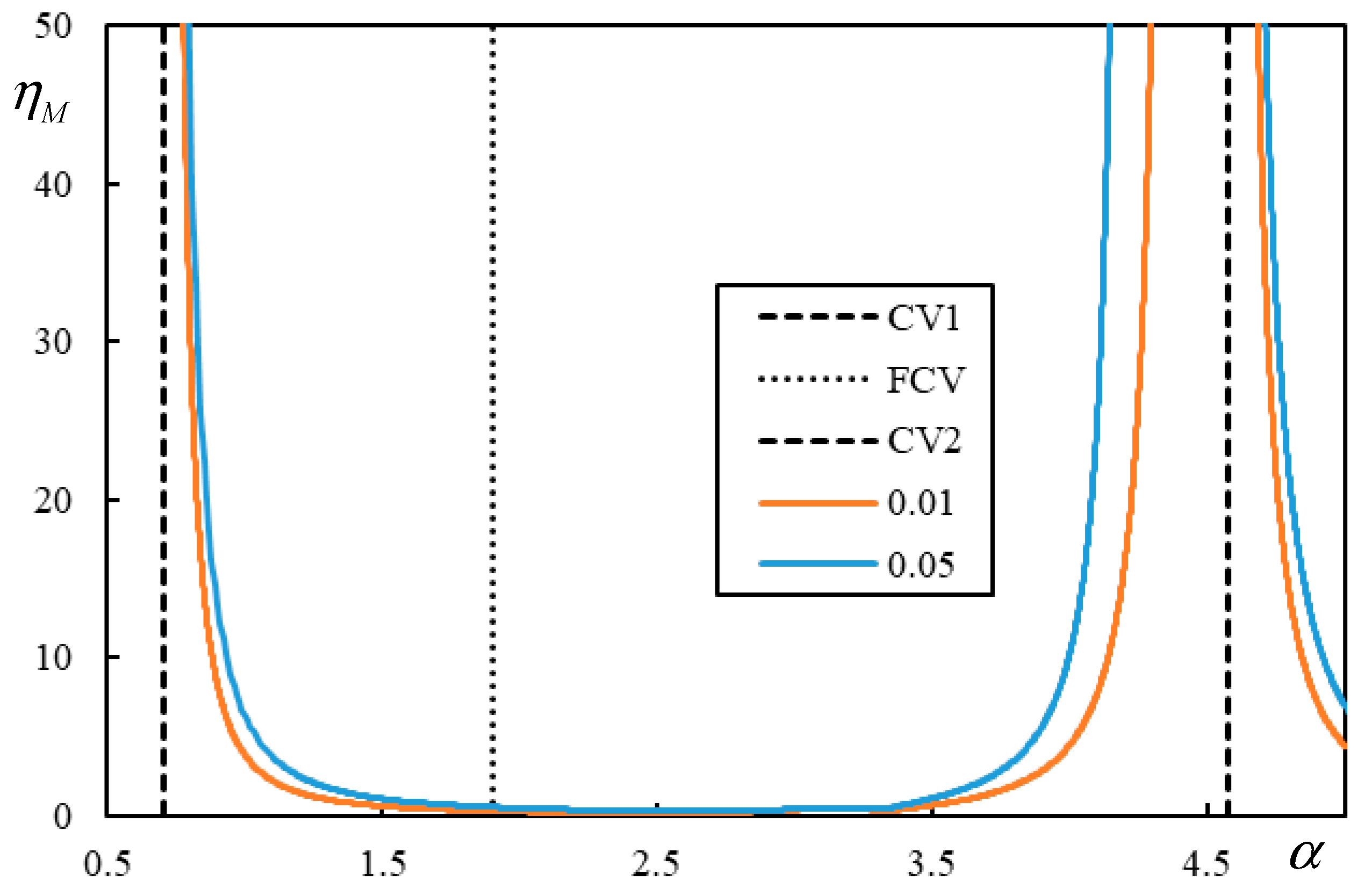
is real and thus the full analysis is kept within the real domain. In regular cases, instability lines are formed by two branches, as demonstrated in
Figure 4. First branch is delimited by CV1 and CV2, tending to infinite
. The second branch approaches CV2 from the left where tend to infinite
and the other end tend to zero
at infinite
. FCV is ignored by instability lines.
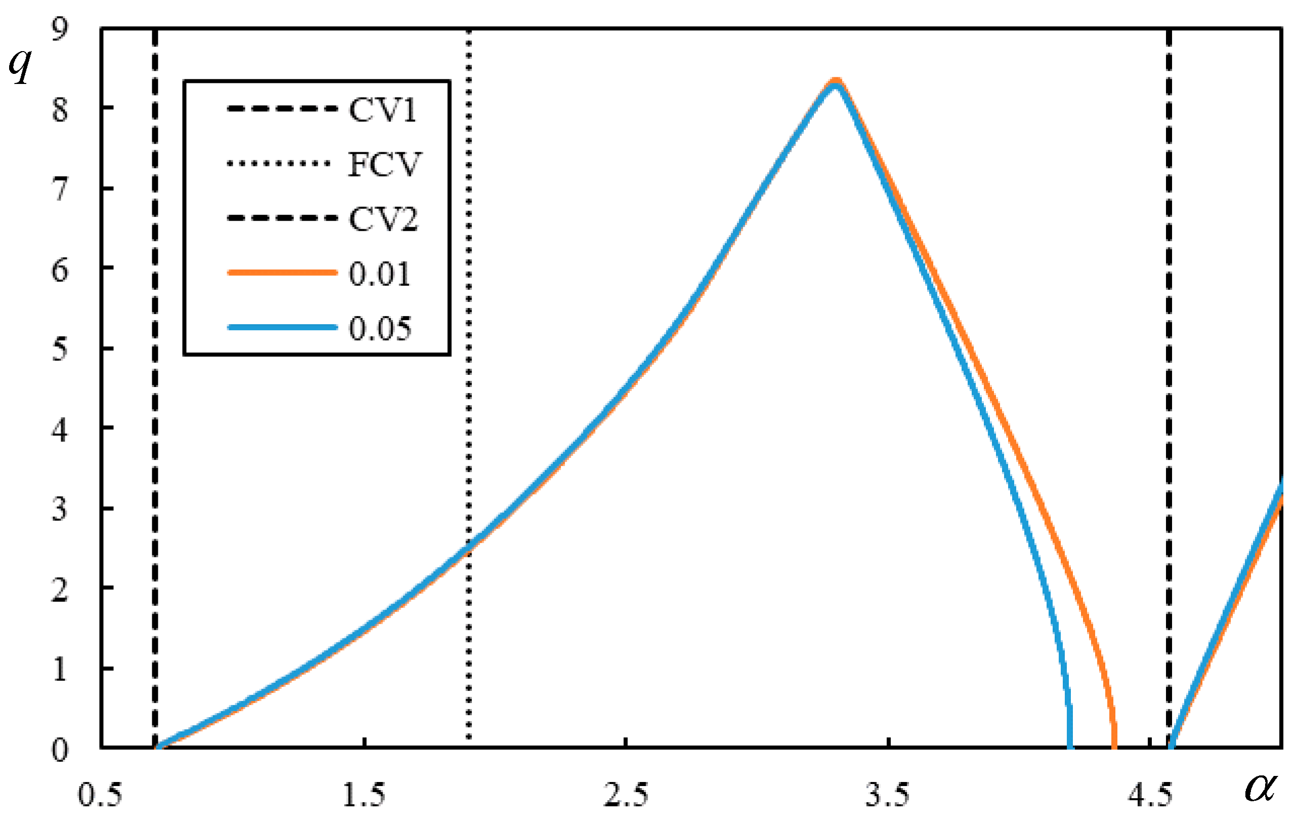
With decreasing damping, instability lines are getting closer to CVs. From
Figure 4 and
Figure 5 it can be concluded that while the left sides of both branches are already quite close to CVs, so the decrease in damping had not much influence, the right part of the first branch is highly affected by damping. The first branch never crosses CV1 or PCV in regular cases, thus instability always occurs in the supercritical velocity range.
The irregular cases are identified by the fact that CV2 is crossed by one of the branches and there can be a third branch, sometimes closed. By parametric analysis within the ranges of allowable parameters it was proven that irregular cases only occur for
on and bellow the line in
Figure 6. The curve in
Figure 6 does not look smooth because the step in
was selected as 0.01 and for
as 0.1, thus the line would turn to be smoother by finer steps.
As an example, one case selected from the irregular region:
and
is discussed in further text. First ILs are presented in
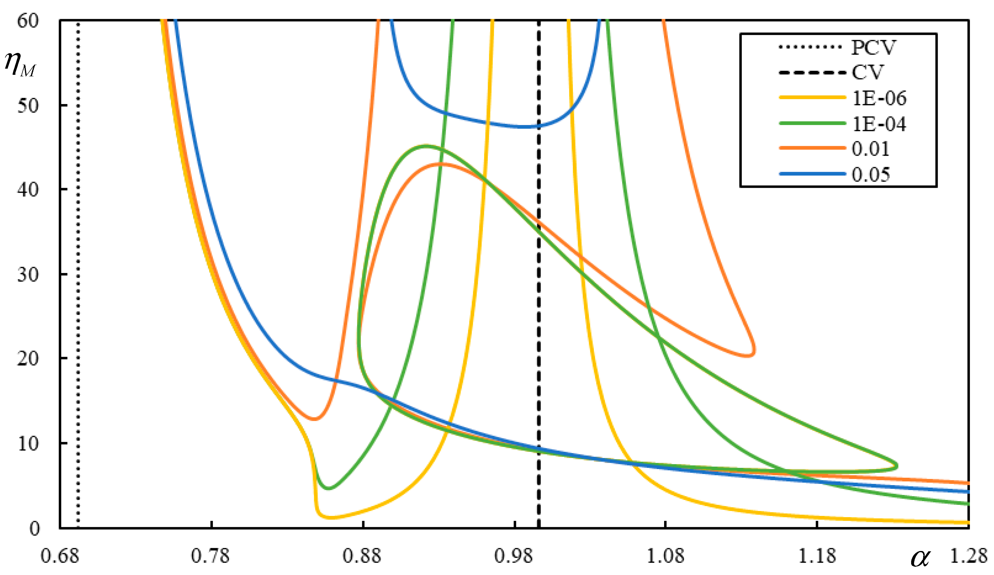
Figure 7 showing the crossings of CV. This case is in fact irregular from the point of view of moving force, thus PCV is plotted in
Figure 7 showing that the role of the lower CV is fully fulfilled.
Figure 7.
ILs for and and four levels of damping as indicated in the legend.
Figure 7.
ILs for and and four levels of damping as indicated in the legend.
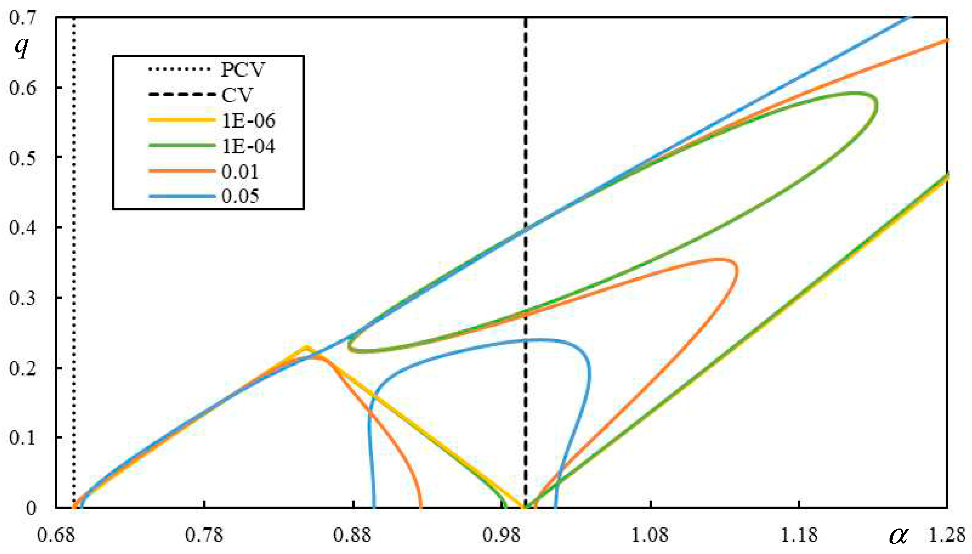
Figure 8.
Real MIFs linked to the ILs from
Figure 7.
Figure 8.
Real MIFs linked to the ILs from
Figure 7.
The level of damping is indicated in the legend. It is considered that both values are equal
. For
and
there are three IL branches from which one of them is closed. This is not very clear from
Figure 7, because the closed branch is overlayed for these two levels of damping. The other two branches have similar behavior as in the regular cases. For
the closed branch is broken and there are only two IL branches. The first one is regular and the second one crosses CV. For
there are also only two branches, but both of them cross CV and have no similarity with regular behavior.
6. Instability of Two Moving Masses
When two masses are traversing the beam, the only difference with respect to the previous analysis is the right-hand side of Eq. (27) which reads as
with additional parameters introduced as
,
and
.
Solution steps can follow the same pattern as before which allows to conclude that the characteristic equation is now
which for
reduces to the characteristic equation of
, as expected.
To simplify the following analysis, it is assumed that
and
. Eq. (41) is not so straightforward for tracing ILs as was Eq. (39), but it is quadratic for
, so it can be solved for
and then two conditions for finding real MIFs can be specified as
Thus, if one of these functions is real for real , then the corresponding can be computed from the associated root, and then negative values are discarded.
After detailed analysis, it can be concluded that when two moving masses are considered, then CVs or PCVs are not respected. Any combination of allowable parameters creates situations where CV1 or PCV are crossed and thus instability occurs in the subcritical velocity range, and also the higher CVs do not serve to indicate the position of the asymptotes.
To identify irregular cases, it is necessary to state when the instability occurs in the subcritical velocity range for a realistic
. In railway applications, mass and moving force are not linked by a mass-to-weight relation. Owing to the primary and secondary suspensions, it is a bit ambiguous what mass should be used in such simplified case. It could be 10t as a typical force transmitted by one wheel or just 880kg which is the wheel mass. Since the value of
can vary between 0.3 to 2.7m
-1, according to
Table 1, then the range for
is 50 – 497 for 10t and 4.5 – 44 for 880kg. It will then be used
as a limit value.
To avoid tracking ILs for all possible cases, the analysis is performed by identifying crossings with a specific MIF value. In fact, only values as low as 0.1-0.15 are worth studying. Thus,
was stepped by 0.1,
by 2, real MIF by 0.01 and
by 0.25 starting at 1. The level of damping was selected as
. The tested region was specified by
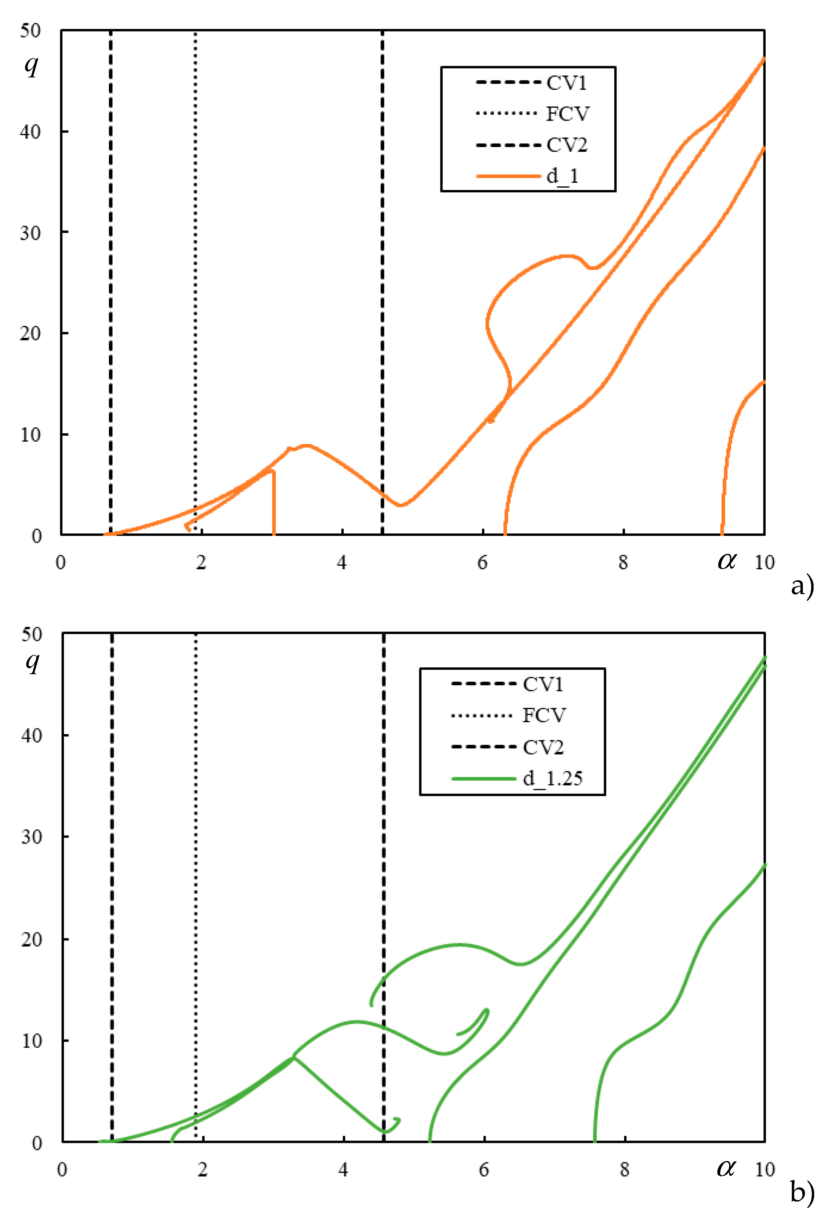
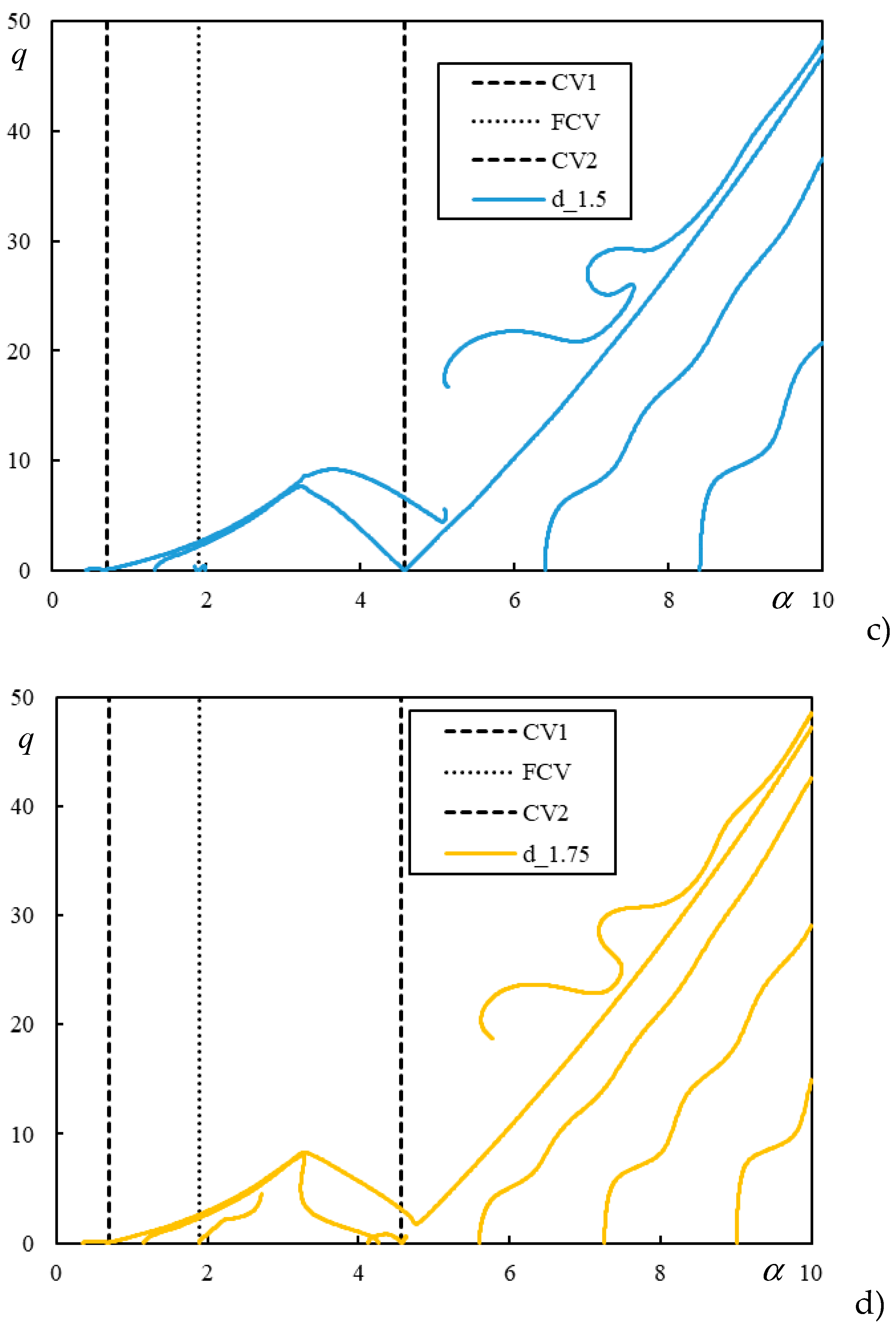
spanning from 0 to the lower CV. The obtained results are presented graphically in
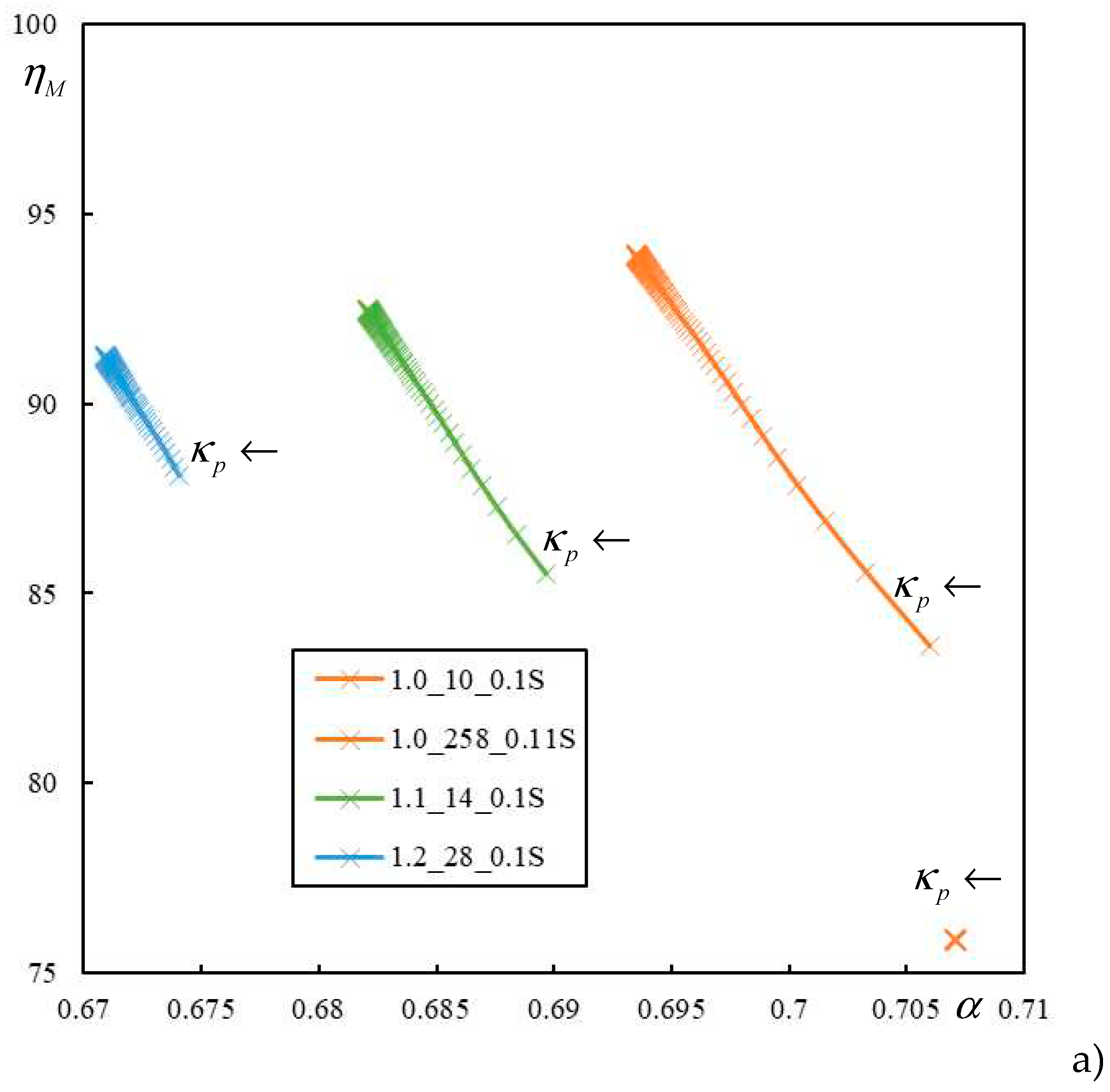
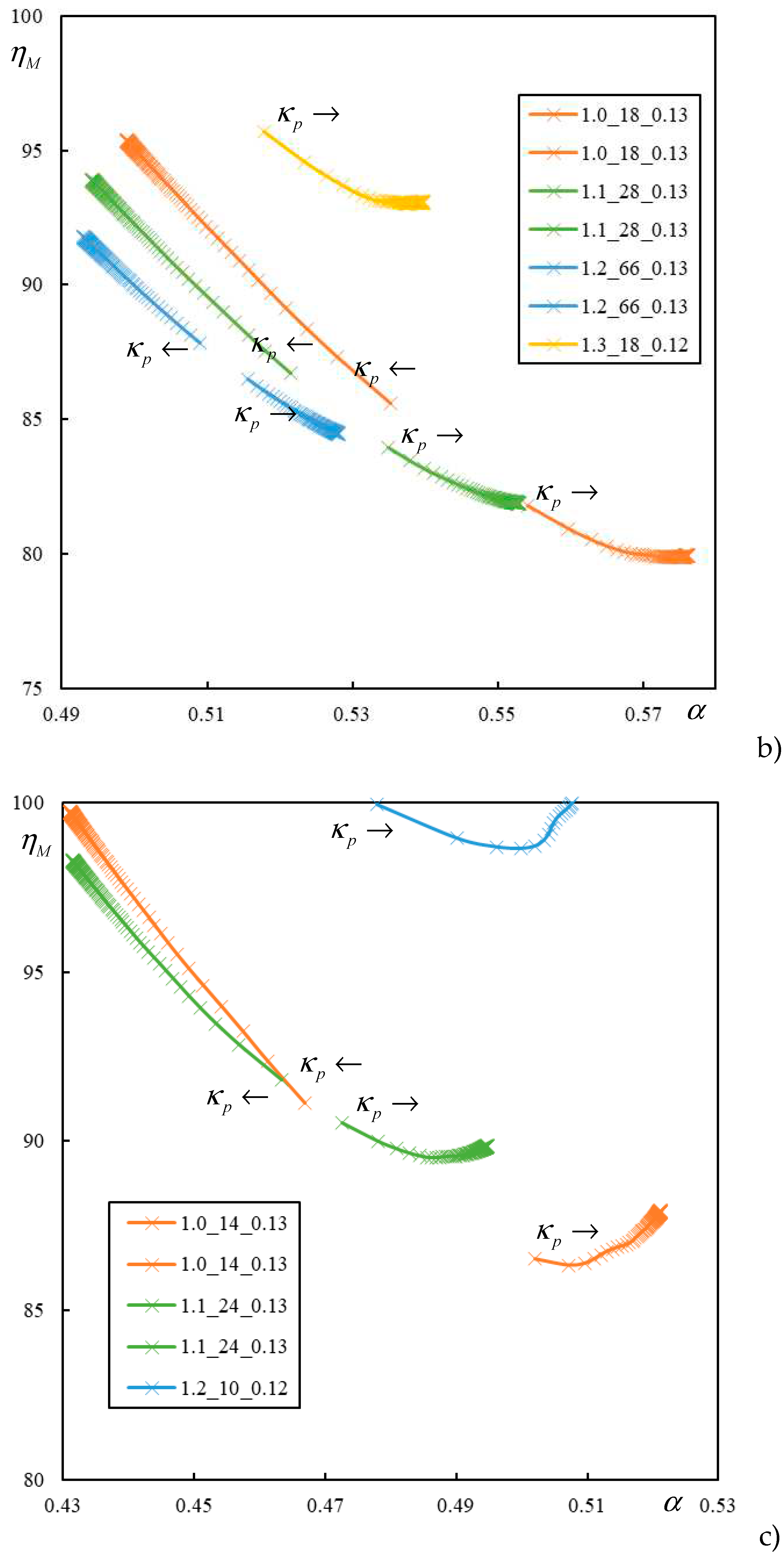
Figure 9.
The graphs in
Figure 9 are limited on the top by
, as concluded before, and on the left by the lower CV or PCV, which varies with
and cannot therefore be directly indicated in these graphs. In
Figure 9a) there are only starting crossings, implying the beginning of a larger unstable region with a higher degree of instability, but for lower
, these values are quite close to the lower CV. In
Figure 9b) and c) there are always two crossings, meaning that they delimitate unstable interval and after that stability is recovered. This also means that in such cases the rate of instability is generally low, lower than in the region with starting branch. No irregular situation was found for
or higher
than indicated in
Figure 9. For simplicity higher values than
were not tested because the tendency is predictable as for such higher values, the crossings are slowly increasing, as obvious from the fact, that the points in graphs are getting closer for constant step in
.
To conclude, the case with
and
, which was regular for one moving mass and now is irregular is further tested with
and for
. All ILs are plotted until
to cover also the region beyond the higher CV. Results of this analysis are presented in
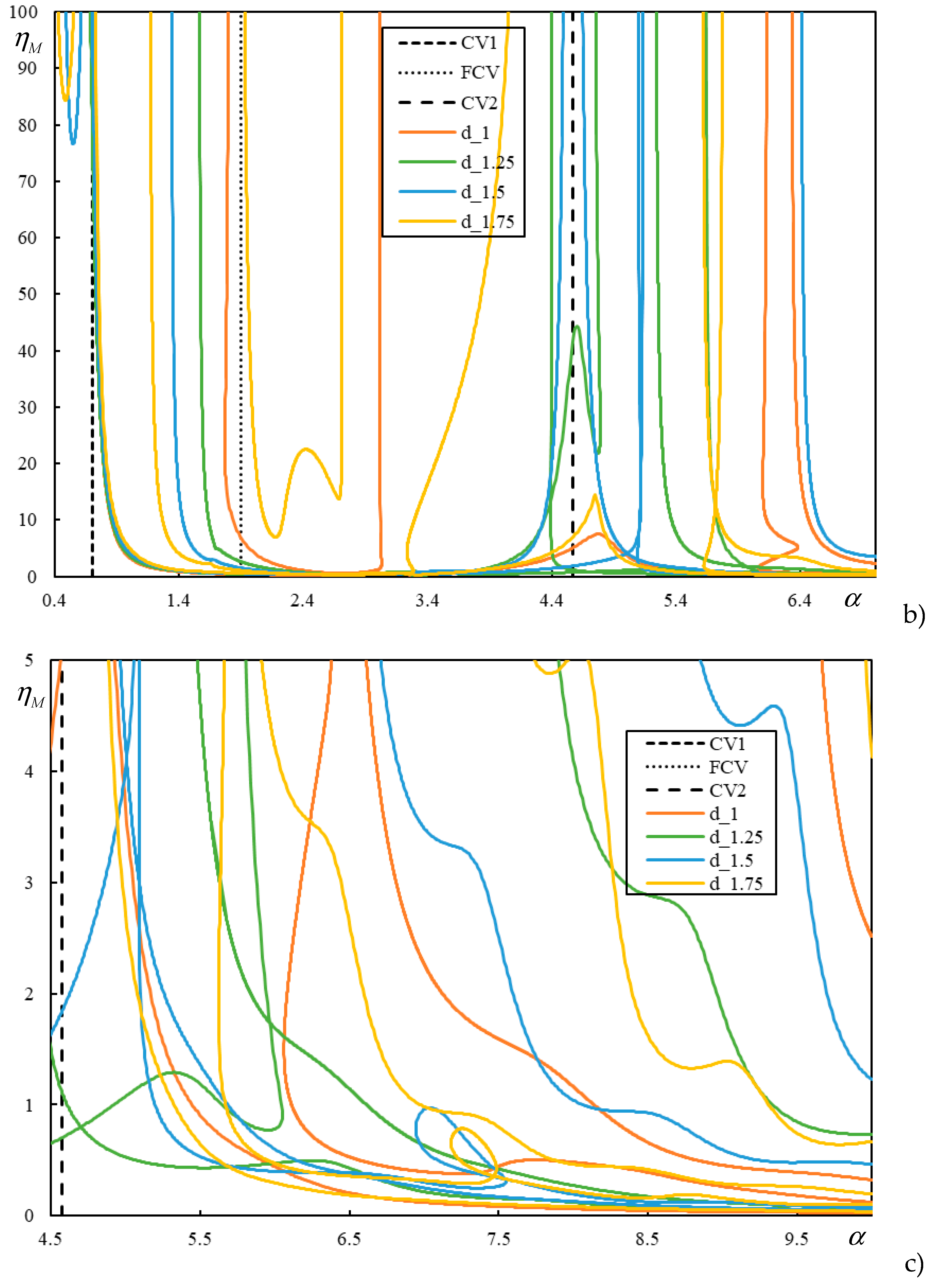
Figure 10 and
Figure 11. In
Figure 10a),
is limited by 1.1, which is more realistic. However, to show how complicated ILs can be, how the number of asymptotes is affected by
and how the relation to CVs and PCV is not fulfilled, also higher range is shown in
Figure 10b) and c), for different scale of
. These graphs should be accompanied by the associated real MIFs, which are reported separately for each
in
Figure 11.
It is worthwhile to compare
Figure 10 with
Figure 9. If the limit of
is imposed, it can be concluded that for
and
there is an unstable interval in subcritical velocity range. Crossings with discrete
reported in
Figure 9 do not indicate the minimum
, but it can be extrapolated. For
there is not value lower than
is subcritical velocity range and for
there is only a starting branch, with values relatively close to the lower CV. It should also be mentioned that by increasing the level of damping, the situation becomes generally worse, [21-22].
7. Conclusions
This paper presents a detailed analysis of a two-layer model for a ballasted railway track. The analysis focused on irregular situations, identified separately for one constant moving force and associated CV, and for one or two moving masses and associated instability velocity intervals, identified by ILs. All results were presented in dimensionless form, mostly analytically or semi-analytically, but without any numerical integration or discretization.
Irregular cases related to CV mean only determination of PCV by parametric analysis. Then at this value there is no real resonance, but an increase in displacements is verified and also the role of PCV in instability issues is preserved. Therefore, this irregularity only requires a different approach in determining the relevant values without suggestions for the railway design.
Regarding the instability of a single moving mass, it was concluded that irregular cases occur throughout the allowable range of , but only at low values of , corresponding to a strong foundation and soft rail pads. However, even this irregularity does not imply any recommendation. It just means that the higher CV is not playing the expected role. So, it can affect instability at very high velocities, which are avoided anyway in real scenarios. An important conclusion is that instability never occurs in the subcritical velocity range, considering the role of PCV.
Therefore, the cases to avoid involve only two moving proximate masses. However, not only the values of
causing instability in the subcritical velocity range are important here, but also how deep these values are located there. Another fact is the rate of instability, generally lower in short closed intervals of instability and higher at the beginning of a larger, possibly semi-infinite interval. The distance between the masses also plays a role. It can certainly be concluded that
and
may represent cases to be avoided when
is low, corresponding to light sleepers such as wooden or similar. In addition,
is also to be avoided, even if the velocity values are not so low, but the rate of instability is expected to be higher. There is no indication that a lower value implies a worse case, except perhaps for
. As for
, this is not true because
is not included in the irregular cases identified in
Figure 9. Regarding to
, this is also not true because, as indicated in the legend of
Figure 9, the starting
value of several lines is quite high.
Acknowledgements
This work was supported by the Portuguese Foundation for Science and Technology (FCT), through IDMEC, under LAETA, project UIDB/50022/2020
References
- L. Frýba, Vibration of solids and structures under moving loads, Research Institute of Transport, Prague (1972), 3rd edition, Thomas Telford, London, 1999.
- D. Basu, N.S.V. Kameswara Rao, Analytical solutions for Euler-Bernoulli beam on visco-elastic foundation subjected to moving load. International Journal for Numerical Analytical Methods in Geomechanics 2013, 37, 945–960. [CrossRef]
- D. Froio, E. Rizzi, F.M.F. Simões, A.P. Da Costa, Universal analytical solution of the steady-state response of an infinite beam on a Pasternak elastic foundation under moving load. International Journal of Solids and Structures 2018, 132–133, 245–263.
- H.A. Dieterman, A.V. Metrikine, Steady state displacements of a beam on an elastic half-space due to uniformly moving constant load. European Journal of Mechanics, A/Solids 1997, 16, 295–306.
- Z. Dimitrovová, Critical velocity of a uniformly moving load on a beam supported by a finite depth foundation. Journal of Sound and Vibration 2016, 366, 325–342. [CrossRef]
- Z. Dimitrovová, Analysis of the critical velocity of a load moving on a beam supported by a finite depth foundation. International Journal of Solids and Structures 2017, 122–123, 128-147.
- H.D. Nelson, R.A. Conover, Dynamic stability of a beam carrying moving masses. Journal of Applied Mechanics, Transactions of the ASME 1971, 38, 1003–1006. [CrossRef]
- G.A. Benedetti, Dynamic stability of a beam loaded by a sequence of moving mass particles. Journal of Applied Mechanics, Transactions of the ASME 1974, 41, 1069–1071. [CrossRef]
- D.G. Duffy, The response of an infinite railroad track to a moving, vibrating mass. Journal of Applied Mechanics 1990, 57, 66–73. [CrossRef]
- A.V. Metrikine, H.A. Dieterman, Instability of vibrations of a mass moving uniformly along an axially compressed beam on a visco-elastic foundation. Journal of Sound and Vibration 1997, 201, 567–576. [CrossRef]
- A.V Metrikine, S.N. Verichev, Instability of vibrations of a moving two-mass oscillator on a flexibly supported Timoshenko beam. Archive of Applied Mechanics 2001, 71, 613–624. [CrossRef]
- B. Yang, H. Gao, S. Liu, Vibrations of a Multi-Span Beam Structure Carrying Many Moving Oscillators. International Journal of Structural Stability and Dynamics 2018, 18, 1850125. [CrossRef]
- S. Roy, G. Chakraborty, A. DasGupta, Coupled dynamics of a viscoelastically supported infinite string and a number of discrete mechanical systems moving with uniform speed. Journal of Sound and Vibration 2018, 415, 184–209. [CrossRef]
- A.S.E. Nassef, M.M. Nassar, M.M. EL-Refaee, Dynamic response of Timoshenko beam resting on nonlinear Pasternak foundation carrying sprung masses. Iranian Journal of Science and Technology, Transactions of Mechanical Engineering 2019, 43, 419–426. [CrossRef]
- T. Mazilu,·M. Dumitriu, C. Tudorache, On the dynamics of interaction between a moving mass and an infinite one-dimensional elastic structure at the stability limit. Journal of Sound and Vibration 2011, 330, 3729–3743. [CrossRef]
- T. Mazilu, Interaction between a moving two-mass oscillator and an infinite homogeneous structure: Green's functions method. Archive of Applied Mechanics 2010, 80, 909–927. [CrossRef]
- T. Mazilu,·M. Dumitriu, C. Tudorache, Instability of an oscillator moving along a Timoshenko beam on viscoelastic foundation. Nonlinear Dynamics 2012, 67, 1273–1293. [CrossRef]
- T. Mazilu, Instability of a train of oscillators moving along a beam on a viscoelastic foundation. Journal of Sound and Vibration 2013, 332, 4597–4619. [CrossRef]
- V. Stojanović, P. Kozić, M.D. Petković, Dynamic instability and critical velocity of a mass moving uniformly along a stabilized infinity beam. International Journal of Solids and Structures 2017, 108, 164–174. [CrossRef]
- V. Stojanović, M.D. Petković, J. Deng, Stability and vibrations of an overcritical speed moving multiple discrete oscillators along an infinite continuous structure. European Journal of Mechanics - A/Solids 2019, 75, 367–380. [CrossRef]
- Z. Dimitrovová, Dynamic interaction and instability of two moving proximate masses on a beam on a Pasternak viscoelastic foundation. Applied Mathematical Modelling 2021, 100, 192–217. [CrossRef]
- Z. Dimitrovová, Two-layer model of the railway track: analysis of the critical velocity and instability of two moving proximate masses. International Journal of Mechanical Sciences 2022, 217, 107042. [CrossRef]
- V. Stojanović, J. Deng, M.D. Petković, D. Milić, Non-stability of a bogie moving along a specific infinite complex flexibly beam-layer structure. Engineering Structures 2023, 295, 116788. [CrossRef]
- V. Stojanović, J. Deng, D. Milić, M.D. Petković, Dynamics of moving coupled objects with stabilizers and unconventional couplings. Journal of Sound and Vibration 2024, 570, 118020. [CrossRef]
- Z. Dimitrovová, Semi-analytical analysis of vibrations induced by a mass traversing a beam supported by a finite depth foundation with simplified shear resistance. Meccanica 2020, 55, 2353–2389. [CrossRef]
- Jahangiri, N.K.A. Attari, A. Nikkhoo, Z. Waezi, Nonlinear dynamic response of an Euler–Bernoulli beam under a moving mass–spring with large oscillations. Archive of Applied Mechanics 2020, 90, 1135–1156. [Google Scholar] [CrossRef]
- A.B. Fărăgău, A.V. Metrikine, K.N. van Dalen, Transition radiation in a piecewise-linear and infinite one-dimensional structure–a Laplace transform method. Nonlinear Dynamics 2019, 98, 2435–2461. [CrossRef]
- A.B. Fărăgău, C. Keijdener, J.M. de Oliveira Barbosa, A.V. Metrikine, K.N. van Dalen, Transition radiation in a nonlinear and infinite one-dimensional structure: a comparison of solution methods. Nonlinear Dynamics 2021, 103, 1365–1391. [CrossRef]
- A.B. Fărăgău, T. Mazilu, A.V. Metrikine, T. Lu, K.N. van Dalen, Transition radiation in an infinite one-dimensional structure interacting with a moving oscillator—the Green’s function method. Journal of Sound and Vibration 2021, 492, 115804. [CrossRef]
- C.G. Koh, J.S.Y. Ong, D.K.H. Chua, J. Feng, Moving element method for train-track dynamics. International Journal for Numerical Methods in Engineering 2003, 56, 1549–1567. [CrossRef]
- K.K. Ang, J. Dai, Response analysis of high-speed rail system accounting for abrupt change of foundation stiffness. Journal of Sound and Vibration 2013, 332, 2954–2970. [CrossRef]
- M.T. Tran, K.K. Ang, V.H. Luong, Vertical dynamic response of non-uniform motion of high-speed rails. Journal of Sound and Vibration 2014, 333, 5427–5442. [CrossRef]
- Jian Dai, Joshua Guan Yi Lim, Kok Keng Ang, Dynamic response analysis of high-speed maglev-guideway system. Journal of Vibration Engineering & Technologies 2023, available on-line.
- Y. Xu, W. Zhu, W. Fan, C. Yang, W. Zhang, A new three-dimensional moving Timoshenko beam element for moving load problem analysis. Journal of Vibration and Acoustics, Transactions of the ASME 2020, 142, 031001. [CrossRef]
- H. Elhuni, D. Basu, Novel Nonlinear Dynamic Beam-Foundation Interaction Model. ASCE Journal of Engineering Mechanics 2021, 147, 04021012. [CrossRef]
- M. Sadri, T. Lu and M. Steenbergen, Railway track degradation: The contribution of a spatially variant support stiffness - Local variation. Journal of Sound and Vibration 2019, 455, 203–220. [CrossRef]
- M. Sadri, T. Lu and M. Steenbergen, Railway track degradation: The contribution of a spatially variant support stiffness - Global variation. Journal of Sound and Vibration 2020, 464, 114992. [CrossRef]
- A.F.S. Rodrigues, Z. Dimitrovová, Applicability of a Three-Layer Model for the Dynamic Analysis of Ballasted Railway Tracks. Vibration 2021, 4, 151–174. [CrossRef]
- Z. Dimitrovová, On the Critical Velocity of Moving Force and Instability of Moving Mass in Layered Railway Track Models by Semianalytical Approaches. Vibration 2023, 6, 113–146. [CrossRef]
- C.J. Yang, Y. Xu, W.D. Zhu, W. Fan, W.H. Zhang, G.M. Mei, A three-dimensional modal theory-based Timoshenko finite length beam model for train-track dynamic analysis. Journal of Sound and Vibration 2020, 479, 115363. [CrossRef]
- A.S.F. Rodrigues, Viability and Applicability of Simplified Models for the Dynamic Analysis of Ballasted Railway Tracks; Ph.D. Thesis, Faculdade de Ciências e Tecnologia da Universidade Nova de Lisboa, Caparica, Portugal: 2017.
- K.N. Van Dalen, Ground vibration induced by a high-speed train running over inhomogeneous subsoil, Transition radiation in two-dimensional inhomogeneous elastic systems, Master Thesis, Department of Structural Engineering, TUDelft, 2006.
- Y-H. Chen, Y-H. Huang, C.-T. Shih, Response of an Infinite Timoshenko Beam on a Viscoelastic Foundation to a Harmonic Moving Load. Journal of Sound and Vibration 2001, 241, 809–824. [CrossRef]
- M.W. Zhai, K.Y. Wang, J.H. Lin, Modelling and experiment of railway ballast vibrations. Journal of Sound and Vibration 2004, 270, 673–683. [CrossRef]
- Z. Dimitrovová, A.S.F. Rodrigues, Critical Velocity of a Uniformly Moving Load. Advances in Engineering Software 2012, 50, 44–56. [CrossRef]
|
Disclaimer/Publisher’s Note: The statements, opinions and data contained in all publications are solely those of the individual author(s) and contributor(s) and not of MDPI and/or the editor(s). MDPI and/or the editor(s) disclaim responsibility for any injury to people or property resulting from any ideas, methods, instructions or products referred to in the content. |
© 2023 by the authors. Licensee MDPI, Basel, Switzerland. This article is an open access article distributed under the terms and conditions of the Creative Commons Attribution (CC BY) license (http://creativecommons.org/licenses/by/4.0/).
