1. Introduction
Wireless power transfer (WPT) has been widely used in electric vehicles, implantable medical equipment, and underwater vehicles [
1,
2,
3]. Due to the change in the position of the receiver coil, the coupling coefficient between the transmitter coil and the receiver coil in the WPT system decreases, resulting in a decrease in the received power and efficiency of the WPT system [
4]. Therefore, the position recognition of the receiver coil is the critical link to realize the stable operation of the WPT system.
The multi-transmitter wireless power transfer system can increase the working area of the transmitter and receiver coil under misalignment and improve the anti-offset performance of the WPT system. Therefore, it has become a research hotspot of wireless power transfer. The self-coupling between the transmitter coils of the array wireless power transfer system will affect each other, reducing the performance of the system and increasing the difficulty of designing the compensation network. Cross-coupling can be reduced by setting a considerable distance between adjacent transmitters. However, excessive spacing between transmitters will cause power and efficiency fluctuations, resulting in unstable power transfer of the WPT system [
5,
6,
7]. The design of a magnetic coupler with unipolar and multi-stage coils helps to reduce the self-coupling between the transmitters [
8,
9]. According to [
10], the coaxial resonant coil adopts a three-layer shielding structure, and the non-coaxial resonant coil adopts a double-layer shielding structure, which can reduce the cross-coupling between the coils. Through the circuit structure design, multiple receivers work at different resonant frequencies, and the corresponding compensation network is designed according to the receiver coil to enhance the selectivity of the receiver coil to the specific frequency power, which can avoid the adverse effects of mutual coupling between multiple receiver coils [
11,
12,
13]. Decoupling between receiver coils can also be achieved by using a controllable capacitor [
14], the controllable inductor [
15], or the decoupling transformer [
16] in the coupling coil to perform cross-coupling impedance compensation. The controllable rectification control can be used to adjust the resonance state of the secondary side [
17,
18]. Different strategies can be adopted from coupling structure, circuit structure, and control strategy to weaken or compensate for the system detuning problem caused by array multi-transmitter coupling.
Whether it is a static or dynamic WPT system, the position detection technology of the receiver coil is critical to improve the performance of the WPT system. The traditional method of obtaining the position of the receiver coil includes sensor detection and adding auxiliary coils. The position detection of the vehicle is realized by adding a magneto-resistive sensor between adjacent transmitter coils [
19]. According to [
10], the bipolar coil is placed symmetrically on the unipolar coil to form a natural decoupling. The position detection of the receiver is realized by monitoring the primary current [
20]. The receiver coil of the WPT system can also be positioned by GPS, infrared detection, ultrasonic positioning, machine vision, radio frequency identification, image processing, and other technologies [
21,
22,
23,
24,
25]. However, by adding additional detection coils and sensors or using other technologies, the cost and complexity of the WPT system will increase. According to [
26], the position of the receiver coil can be estimated by comparing the induced voltage in the transmitter coil during the movement of the receiver coil. The position of the receiver coil in the WPT system can also be estimated by calculating the amplitude and phase of the current in the transmitter coil [
27,
28,
29]. However, these methods can only detect the position of the receiver coil in a single direction and are unsuitable for planar position detection.
By constructing an offline training set as a reference, the algorithm is used to search the position closest to the measured value, and the position estimation of the receiver coil on the plane can be realized [
30,
31]. However, this method is easily affected by electromagnetic environment disturbance. The position recognition of the receiving coil on the 2D plane can be realized by setting 12 sensor arrays [
32]. By adding a detection circuit, the position detection of the receiving coil on the plane can be realized [
33]. However, these methods will increase the complexity and volume of the WPT system. According to [
34], the position identification of the receiver coil in the whole 2D plane can be realized by detecting the current and voltage of the magnetic integrated structure. However, the cross-coupling between multiple transmitter coils is ignored.
This paper adopts a 3×3 array transmitter with different overlapping surfaces and a cascade mode of four inverters and nine transmitters. The mathematical model of mutual inductance between the receiver and transmitter coils at different positions on the X-Y plane is established. A position recognition method of the receiver coil on the X-Y plane based on the receiver coil current is proposed.
2. Array multi-transmitter wireless power transfer system
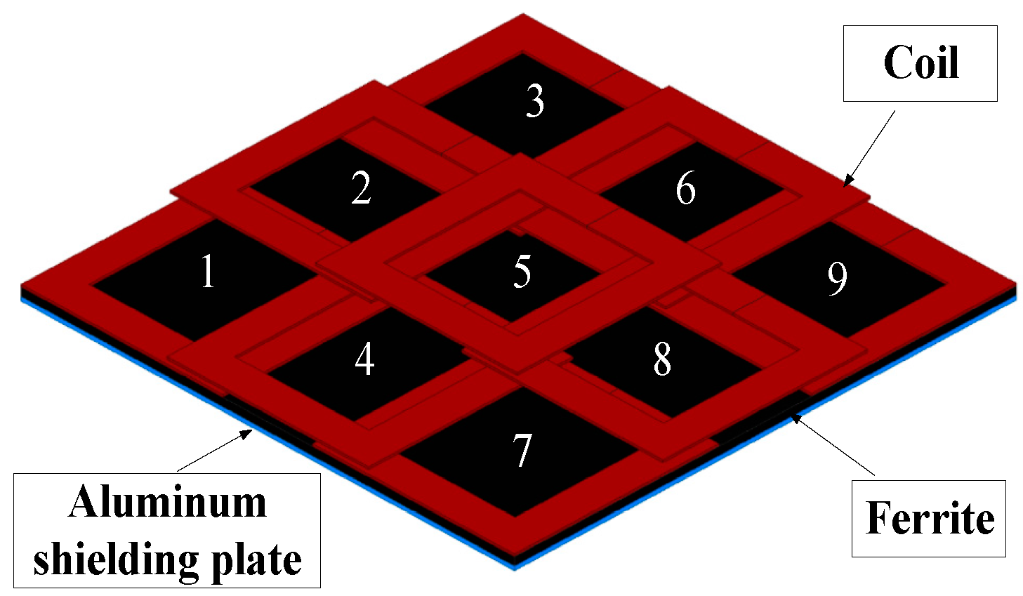
There is cross-coupling between the transmitter coils of the array transmitter coil. The power exchange between the transmitter coils increases the power loss of the WPT system and hinders the transfer of power from the transmitter to the receiver. Therefore, the array transmitter coil needs to be decoupled. The optimized 3×3 array transmitter coil is shown in
Figure 1.
2.1. Array transmitter coils with different overlapping surfaces
This section may be divided by subheadings. It should provide a concise and precise description of the experimental results, their interpretation, as well as the experimental conclusions that can be drawn.
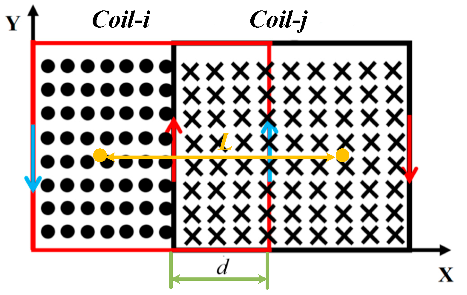
This paper decouples by adjusting the overlapping area between two adjacent transmitter coils, as shown in
Figure 2. By changing the length L between the centers of two adjacent coils, the magnetic flux
of the coil-
i is equal to the penetrating flux
of coil-
j in size and the opposite direction to realize the decoupling between two adjacent coils[
35].
Because the mutual inductance between non-adjacent transmitter coils can be ignored [
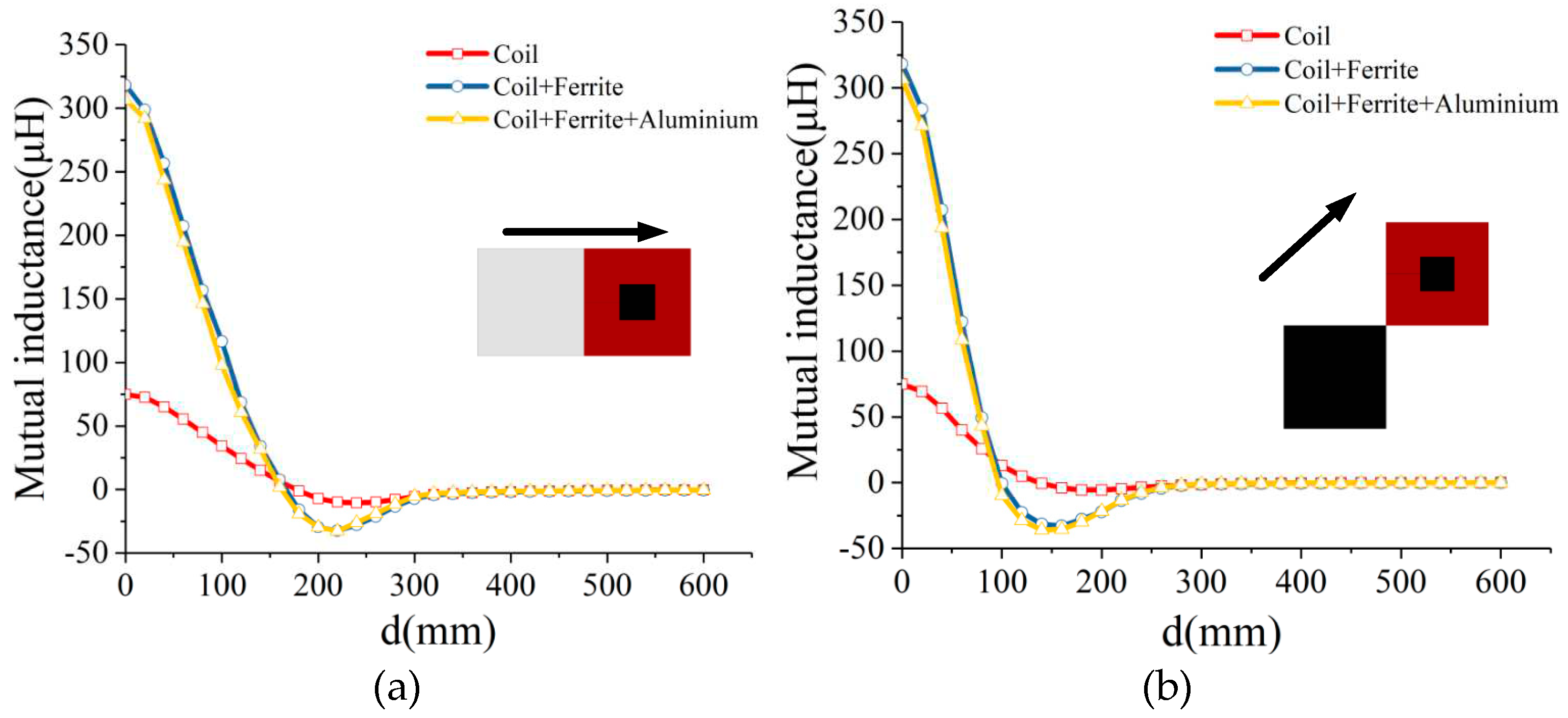
36], the mutual inductance between adjacent transmitter coils on the line and diagonal is obtained by simulation in
Figure 3. The simulation model of coil size is 300mm×300mm×10mm, the ferrite size is 300mm×300mm×5mm, and the aluminum plate size is 300mm×300mm×2mm. The ferrite is located on the back of the coil, which increases the mutual inductance between the transmitter and receiver coil and provides a low magnetoresistance path for the magnetic flux. The aluminum shielding plate reduces the magnetic field leakage on the back of the coil and reduces external electromagnetic interference. The receiver coil moves along the transmitter coil's adjacent straight and diagonal lines. Due to the structure of the coil under linear movement and diagonal movement being identical, the maximum mutual inductance between the coils is 75.2μH, the maximum mutual inductance between the ferrite coils is 312.7μH, and the maximum mutual inductance between the ferrite aluminum plate coils is about 324.6μH. Because the change of the overlapping area between the coils under the diagonal adjacent coil movement is more significant than the straight adjacent coil movement, the mutual inductance between the adjacent diagonal coils decreases significantly at the same moving distance.
2.2. The connection mode of multiple transmitter coils and the cascaded topology of the inverter
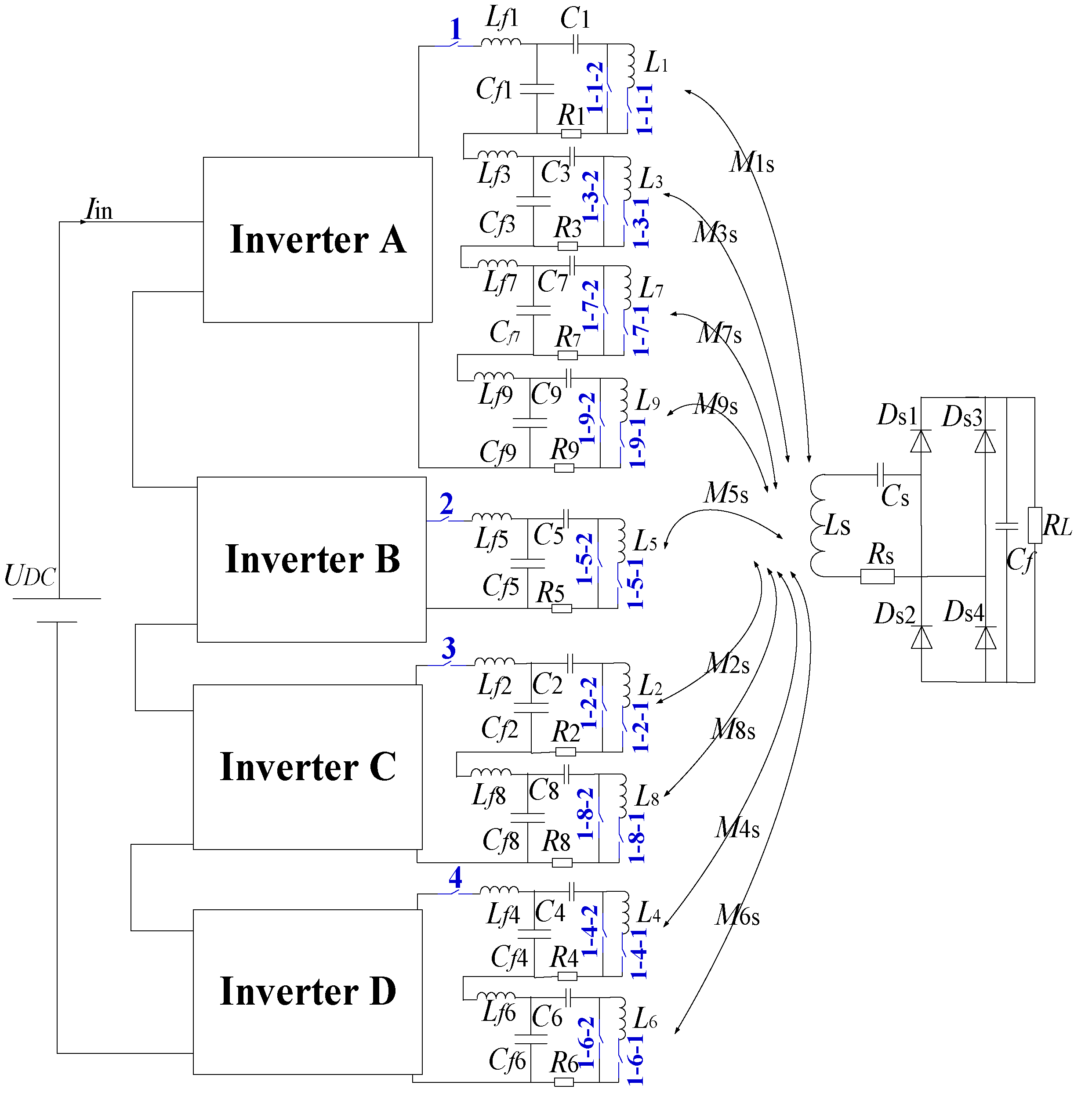
The array of multiple transmitter coils is controlled by a single inverter single transmitter coil, which has low transfer power and weak anti-interference ability. It is impossible to fully use the cooperative work of multiple transmitter coils to realize wireless power transfer of multiple transmitter single receivers. This paper proposes a 3×3 group logic and control strategy for array transmitters. The logic switch control method of the multi-transmitter coil array can realize the cooperative work of any number of coils, connected dual transmitter coils, and adjacent four transmitter coils. Without changing the coil topology, three different working modes of multiple transmitter coils are switched by short-circuit jumper and open-circuit series switch. The block diagram of the array multi-transmitter WPT system is shown in
Figure 4.
Four inverters control nine multi-transmitter coils to achieve conflict-free control to achieve any four-coil adjacent working mode. The switching control of different working modes of the array transmitter coil (
Figure 1) is realized by four inverters, and the grouping logic of multiple transmitter coils is shown in
Figure 4. All switch components (1,2,3,4,1-1-1, 1-1-2, 1-3-1...) are AC contactor CJX2-1810. The transmitter coil 5 is in the middle of the array of multi-transmitter coils for different four-transmitter coil modes and is driven by a separate inverter B. For inverter A, four non-adjacent coils need to be connected. Any coil can be connected and disconnected by an open-circuit series switch. Inverters C and D are connected to the corresponding transmitter coils on the array of multiple transmitters. The working mode of the transmitter coil can be divided into single transmitter, dual transmitter, and four transmitters. In the single transmitter coil mode, the corresponding inverter channel is selected by the position identification of the receiver coil, the open circuit series switch of the target coil is closed, and the short circuit frequency division switch of the corresponding target coil is disconnected, to realize the single power supply of the target coil. In the dual transmitter coil mode, the corresponding inverter channel can be selected by identifying the position of the receiver coil, and the corresponding dual transmitting coil can be closed by disconnecting the short-circuit jumper switch of the target. In the dual transmitter coil mode, the power supply can be realized. In the four-transmitter coil mode, the corresponding inverter channel can be selected by identifying the position of the receiver coil and closing the open-circuit series switch to disconnect the short-circuit crossing control of the corresponding four transmitter coil and the power supply of the four-transmitter coil mode can be realized. The three working modes of the multi-transmitter coils and the sequence number of the working coils are shown in
Table 1.
3. Receiver position recognition method for multi-transmitter WPT system
3.1. Circuit model analysis of multi-transmitter WPT system
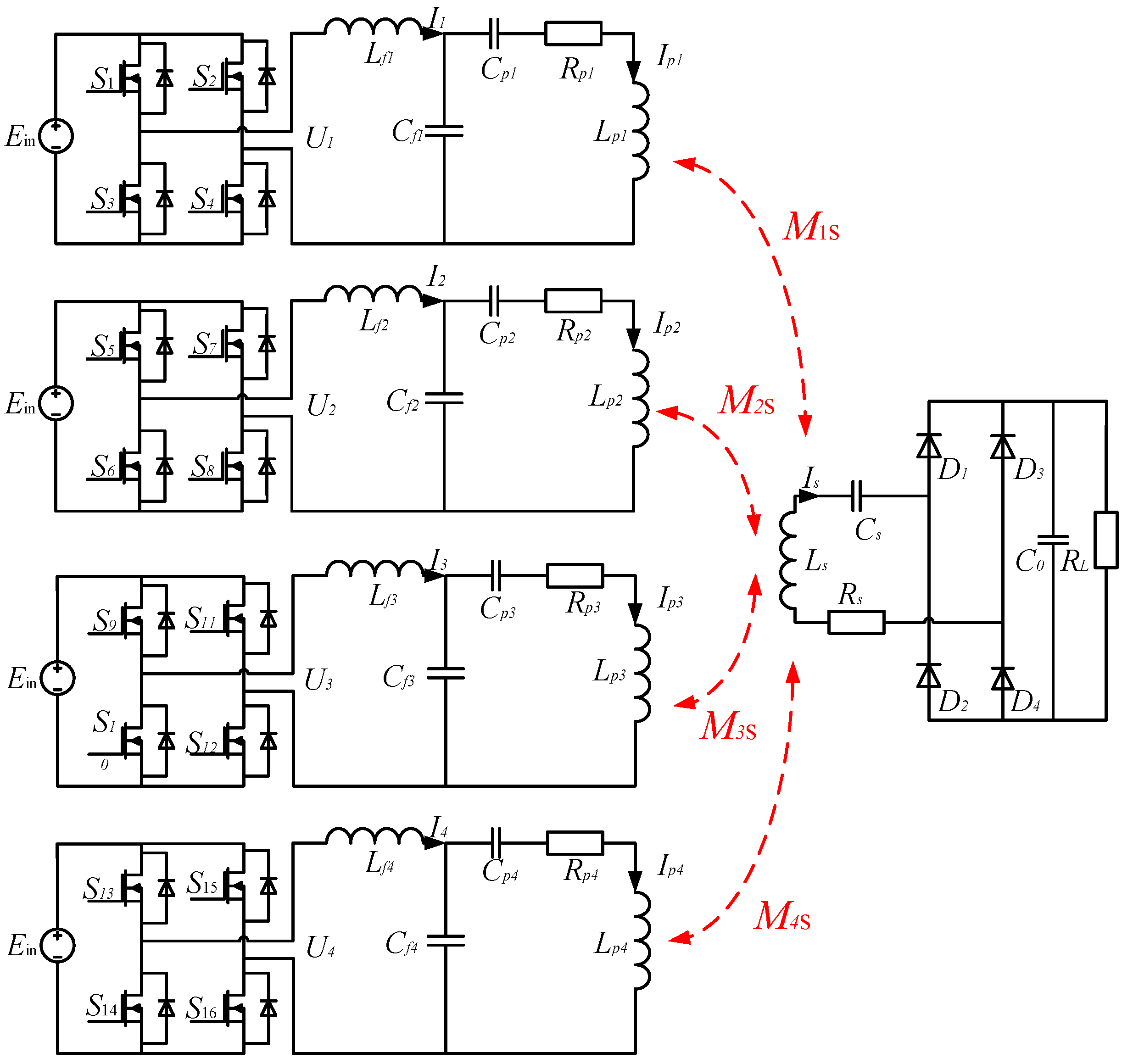
The parameters of the transmitters and the compensation network in the equivalent circuit of the multi-transmitters WPT system are theoretically symmetrical. The single transmitter of the multi-transmitter WPT system in
Figure 5 works in a single resonance:
According to Kirchhoff’s voltage law:
The variables in the formula are defined as follows:
In the resonant state, the circuit parameters of the system can satisfy the following:
The current flowing through the resonant inductor Lf, the transmitter coil LT, and the receiver coil LR on the LCC-S resonant network can be calculated:
is the inverter output voltage of the
i-th branch;
is the mutual inductance between the transmitter coil and the receiver coil of the i-th branch. The mutual inductance between the transmitter coil and the receiver coil is:
The DC input voltage Ein, the compensation inductance Lf(i), the coil internal resistance Rs, and the equivalent internal resistance Re=8RL/π2 is the rear stage circuit of the rectifier bridge are determined. Monitoring the receiver coil current Is(i) can obtain the mutual inductance M(i)s between the transmitter and receiver coils. The receiver coil current Is(i) correlates with the mutual inductance M(i)s between the transmitter and receiver coils. The greater the mutual inductance value, the greater the receiver coil current. The mutual inductance between the receiver coil and the different coils of the transmitter can be obtained by substituting equation (8).
3.2. Circuit model analysis of multi-transmitter WPT system
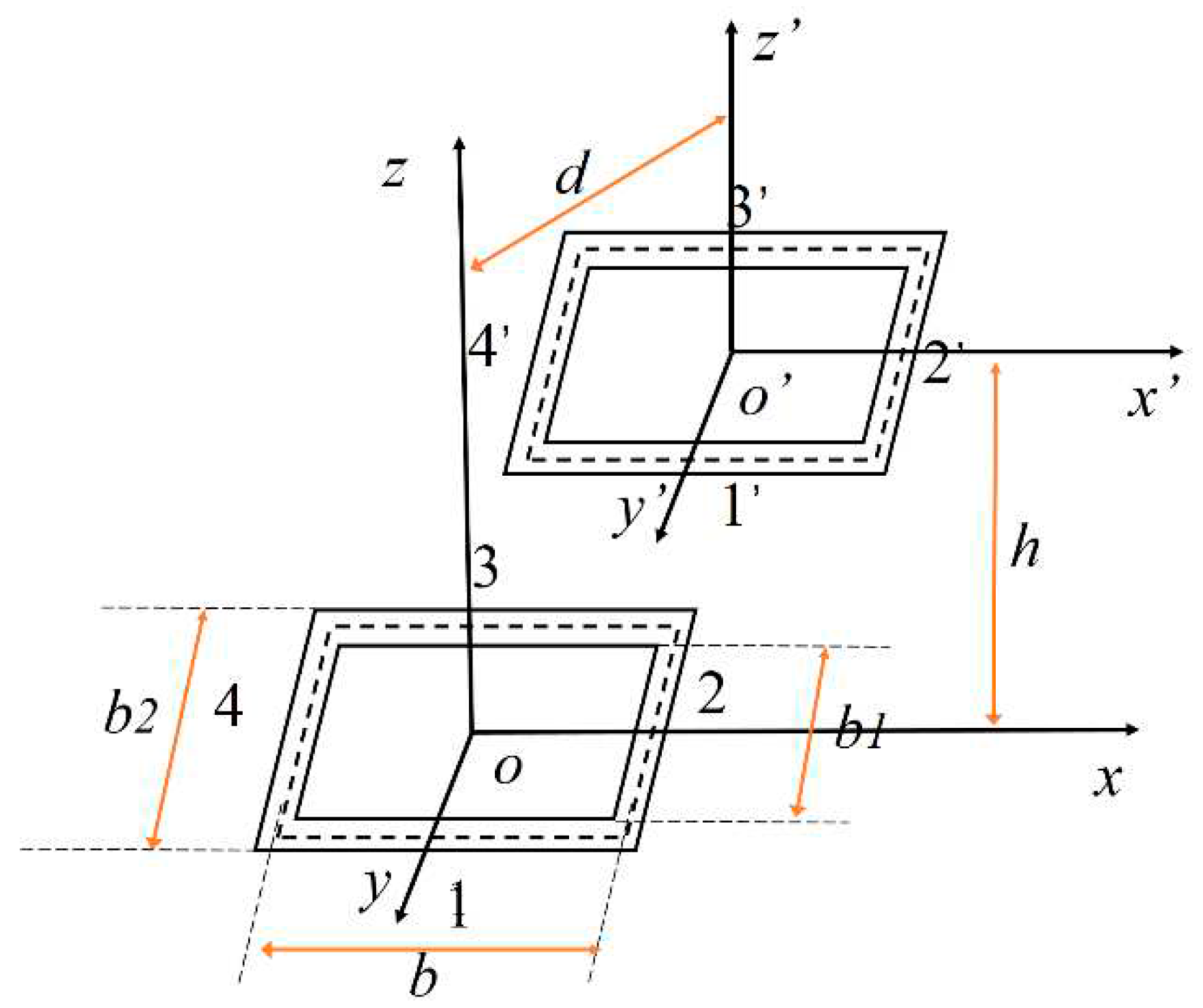
The receiver coil is in the X-Y working plane of the array multi-transmitters WPT system. The mutual inductance model of a single-transmitter signal-receiver coil is established to calculate the mutual inductance between transmitter and receiver coils. As shown in
Figure 6,b1 is the inner diameter of the coil, b2 is the outer diameter of the coil, and b is the equivalent radius of the coil.
The diameter of the coil wire is D, the number of turns is N, and the relationship between the outer diameter and the inner diameter of the coil is:
The equivalent side length of the coil is b, the lateral offset distance of the centre line of the two square coils is d, the axial vertical distance is h, and the centre coordinates of the coils are
and
, respectively, as shown in
Figure 7. The mutual inductance between wires 1 and 1’ is :
The mutual inductance value of the square coil is obtained.
The transmitter and receiver coil structure with no horizontal offset. The mutual inductance
between the primary and second coils is:
The mutual inductance of the two square coils is the largest when the offset is zero. The two square coils are horizontally offset, and the mutual inductance decreases with the offset increase. Therefore, the position of the receiver coil can be estimated according to the different mutual inductance values when the receiver coil is at various places in the working area of the array of transmitter coils.
3.3. Position identification method of the receiver coil
The secondary coil current can obtain the mutual inductance between the primary receiver coil and the transmitter coil, and the offset distance of the receiver coil relative to each transmitter coil can be obtained by the mutual inductance model. Therefore, this section focuses on establishing a mathematical model of the secondary coil current at different positions in the X-Y plane to realize the position identification of the receiver coil. It is not easy to directly solve the mutual inductance expression of the receiver and transmitter coils at different positions on the plane. This paper obtains the mathematical model of mutual inductance between the receiver coil and different transmitter coils in other places by polynomial approximation. The transmitter coils 1, 3, 7, and 9 are located at the four corners of the array transmitter coil. The mutual inductance of the transmitter and receiver coils changes significantly, and the electromagnetic interference is relatively small. The open-circuit series switch and short-circuit cross switch on inverter A can realize the switching between the transmitter coils. Therefore, the transmitting coils 1, 3, 7, and 9 are selected as the detection coils. However, due to the limited effective coupling area of the transmitter coil, only selecting transmitter coils 1,3,7, and 9 as the position detection coils will lead to some weak coupling regions in the middle region of the transmitter coil array. Since the mutual inductance between the transmitter and the receiver coil caused by the change of the receiver coil position does not change much, the intermediate transmitter coil 5 is selected to compensate for the weak coupling area of the multi-transmitter centre. The mutual inductance values of the receiver coil at different positions in the working area plane of multiple transmitter coils and other transmitter coils 1, 3, 5, 7, and 9 are calculated by Maxwell. After inputting them as sample data, the equations are constructed to solve the mutual inductance mathematical models corresponding to the receiver coils and different transmitter coils. The calculation process of receiver and transmitter coil 1 is illustrated as an example. The mutual inductance values of the receiving coil and the transmitter coil 1 at different positions on the working plane are obtained and used as samples.
The following binary polynomial function is used to fit the sample data:
The objective function can be expressed as:
Solving the objective equation requires the coefficient matrix A. By repeating the above steps, the mutual inductance mathematical models of the receiver coil and the transmitter coil at different positions on the working plane can be obtained, respectively. The accuracy of the mathematical model and the actual data is characterized by fitting the characteristic quantities RMSE(Root Mean squared error) and R-square(Coefficient of determination).
SSE (Sum of Squares for Error): The closer the RMSE is to 0, the higher the accuracy of the mathematical model and the actual data, and the more reliable the data model is.
The closer the R-square is to 1, the better the fitting between the mathematical model and the experimental data is. SSR (Sum of squares of the regression); SST (Total sum of squares).
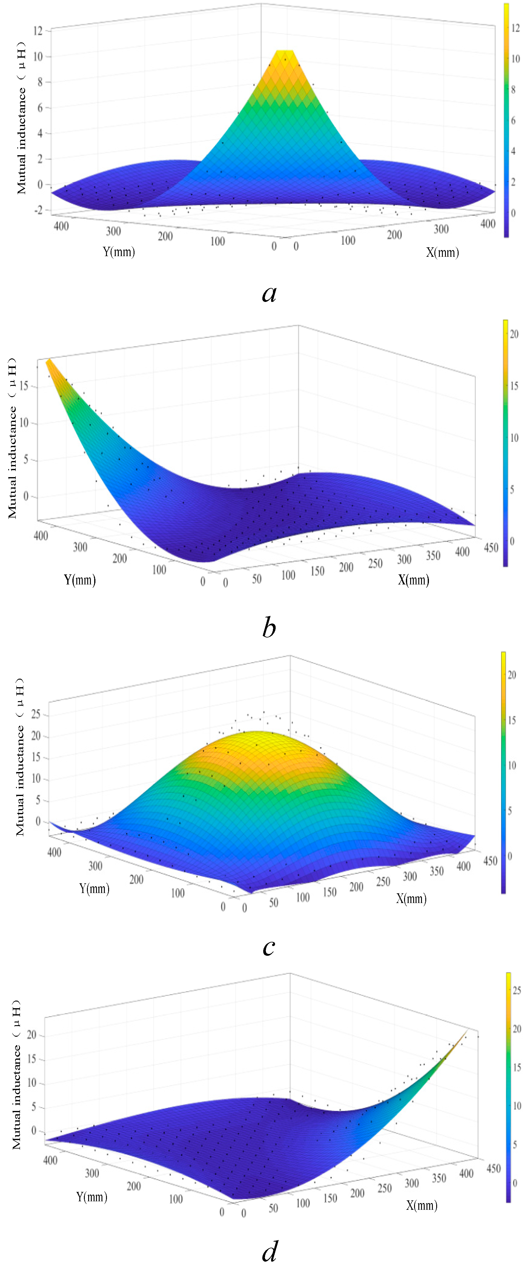
The mutual inductance of the receiver coil and different transmitter coils 1, 3, 5, 7, and 9 at different positions on the same plane is obtained by finite element simulation. The mathematical model of mutual inductance between other transmitting coils and receiver coils is established by polynomial fitting :
Figure 7.
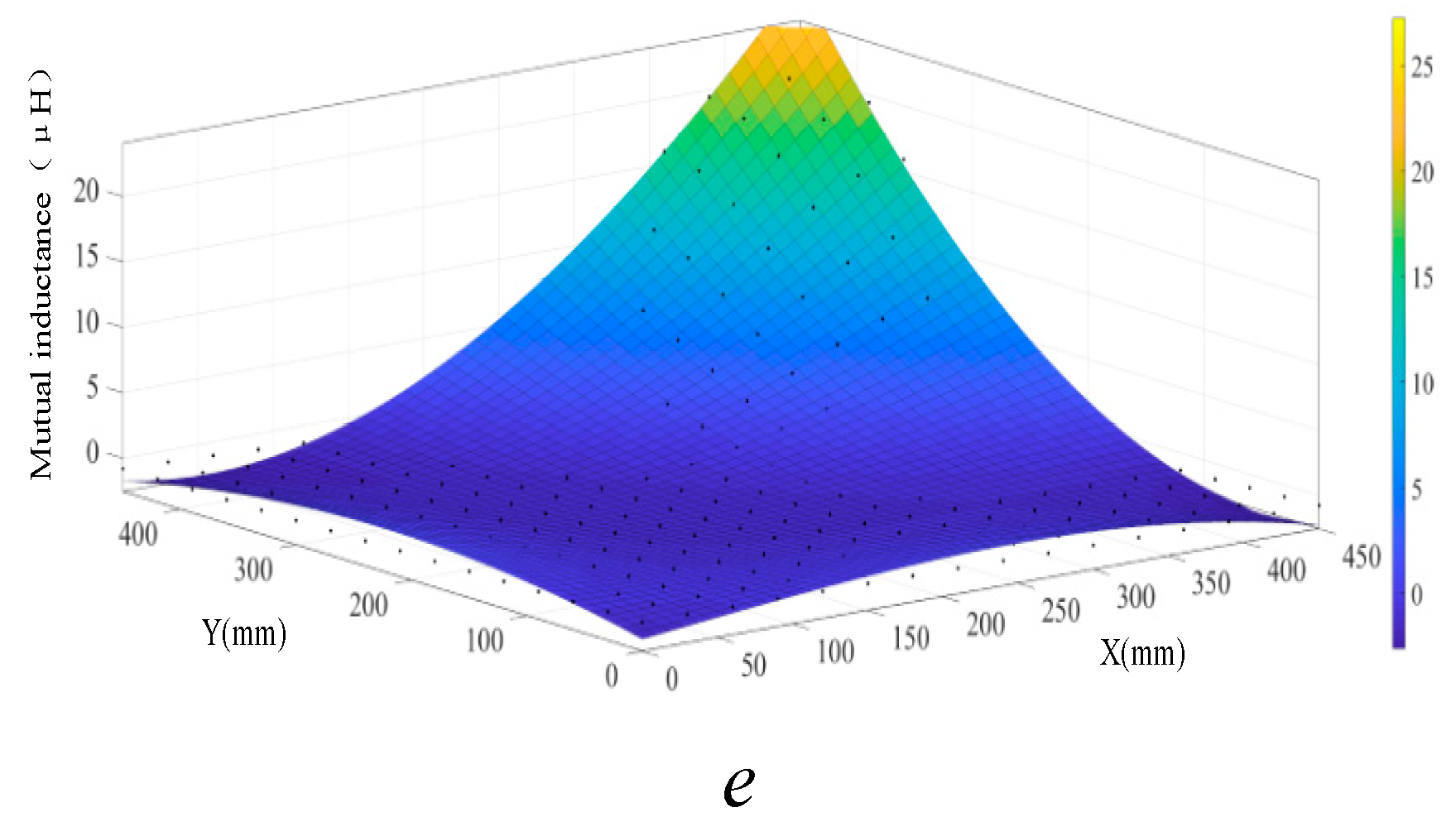
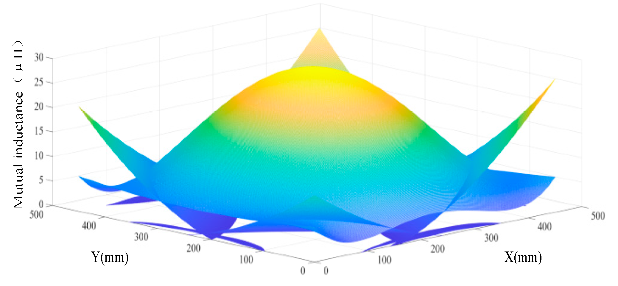
Mutual inductance curves of different transmitter coils and receiver coil. (a) transmitter coil1 (b) transmitter coil3 (c) transmitter coil5 (d) transmitter coil7 (e) transmitter coil9.
Figure 7.
Mutual inductance curves of different transmitter coils and receiver coil. (a) transmitter coil1 (b) transmitter coil3 (c) transmitter coil5 (d) transmitter coil7 (e) transmitter coil9.
According to
Figure 7, the predicted values of the mutual inductance curves of the transmitting coils 1,3,5,7 and 9 almost coincide with the simulated mutual inductance points. The RMSE of the fitting equation of the mutual inductance curve between the transmitter coil 1, 3, 7, 9 and the receiving coil is less than 1, the RMSE of the fitting equation between the transmitter coil 5 and the mutual inductance curve is less than 2, and the R square is more significant than 0.92, which is close to 1. It shows that the mutual inductance model of each transmitter fits well with the mutual inductance curve of each transmitter coil and receiver coil. The mutual inductance model has high reliability and accurate data prediction.
Table 2.
Evaluation parameters of data fitting characteristics.
Table 2.
Evaluation parameters of data fitting characteristics.
| Serial number |
RMSE |
R-square |
| 1 |
0.6640 |
0.9232 |
| 3 |
0.9004 |
0.9455 |
| 5 |
1.7866 |
0.9498 |
| 7 |
0.9974 |
0.9614 |
| 9 |
0.9946 |
0.9616 |
Figure 8 shows that the mutual inductance curves of the receiver coil and the transmitter coil 1,3,5,7,9 intersect on the working plane 100 mm above the transmitter coil, and transmitter coil 5 effectively compensates for the weak coupling region in the array transmitter coil.
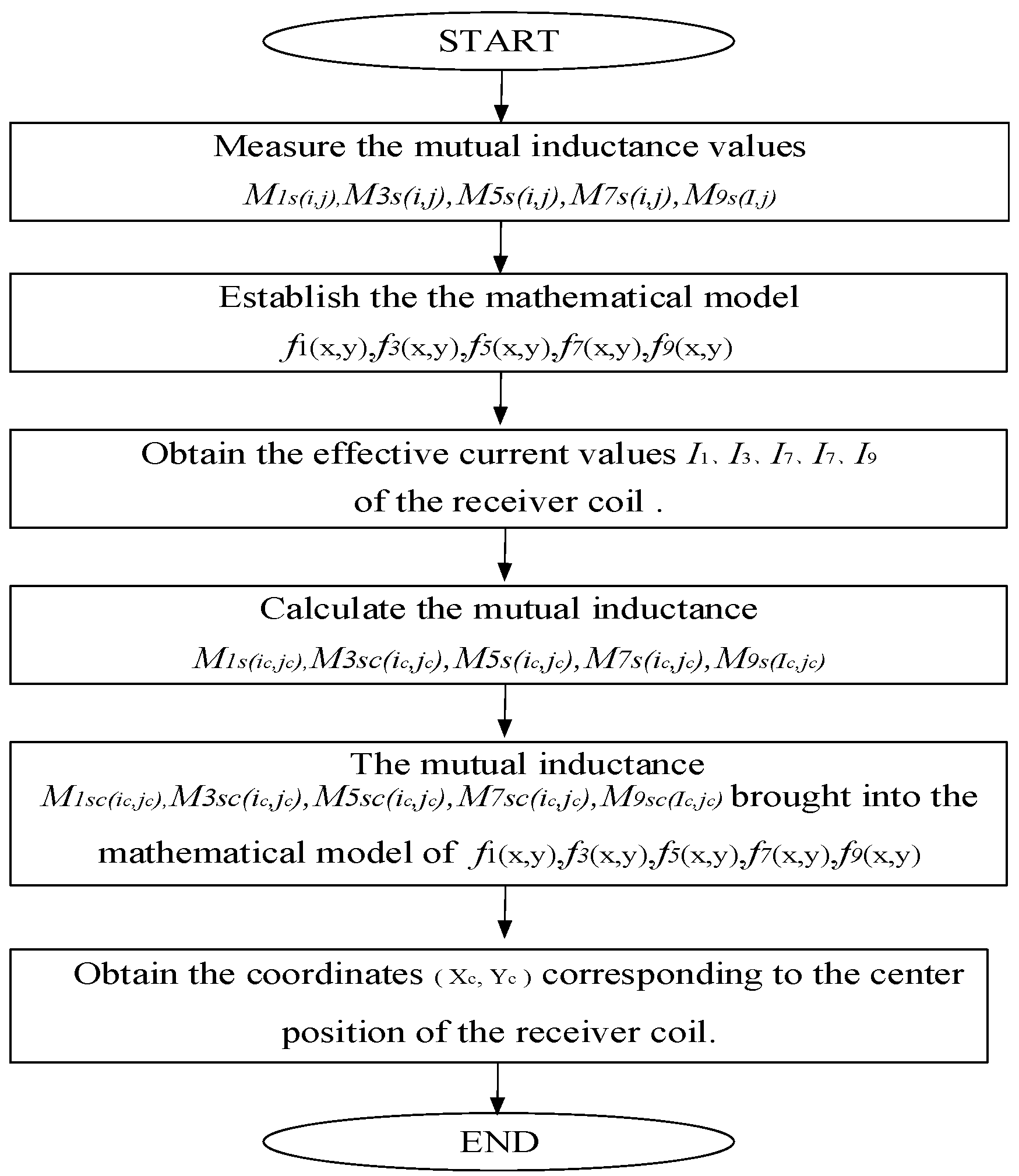
Therefore, the receiver coil is on the plane with a height of h on the transmitter coil, and the centre of the receiver coil is . Through the open circuit series switch and the short circuit jumper switch, the transmitter coils 1,3,5,7 and 9 are turned on, respectively. And the receiver coil current is monitored and recorded when the receiver coil is in position to turn on the transmitter coils 1,3,5,7 and 9. The mutual inductance value M1s, M3s, M5s, M7s, and M9s of the receiver coils and different transmitters is obtained by formula (6), and the corresponding position of the receiver coil can be solved by formula (20).
4. Experimental verification
According to the current calculation of the receiver coil, the mutual inductance values of the receiver coil and different transmitter coils at different positions on the same plane are obtained, and the offset distance between the receiver coil and other transmitter coils is determined. The receiver coil position recognition algorithm ensures the centre position of the receiver coil. This paper will verify the feasibility of the planar position detection scheme based on the array multi-transmitter WPT experimental platform. The parameters of each channel device on the primary side are theoretically completely symmetrical. The primary/secondary coil is square, with an outer diameter of 300mm×300mm and an inner diameter of 100mm × 100mm. The coil self-inductance Lp is 102.48μH, the primary side compensation inductance Lf is 45.18μH, the primary side parallel compensation capacitor Cf is 77.932nF, the primary side series compensation capacitor Cp is 60.994nF, the secondary series compensation capacitor Cs is 34.211nF, and the load resistance is 10Ω. The operating frequency of the inverter is 85kHz, and the phase of the inverter that opens the transmitting coil 1,3,5,7,9 is consistent.
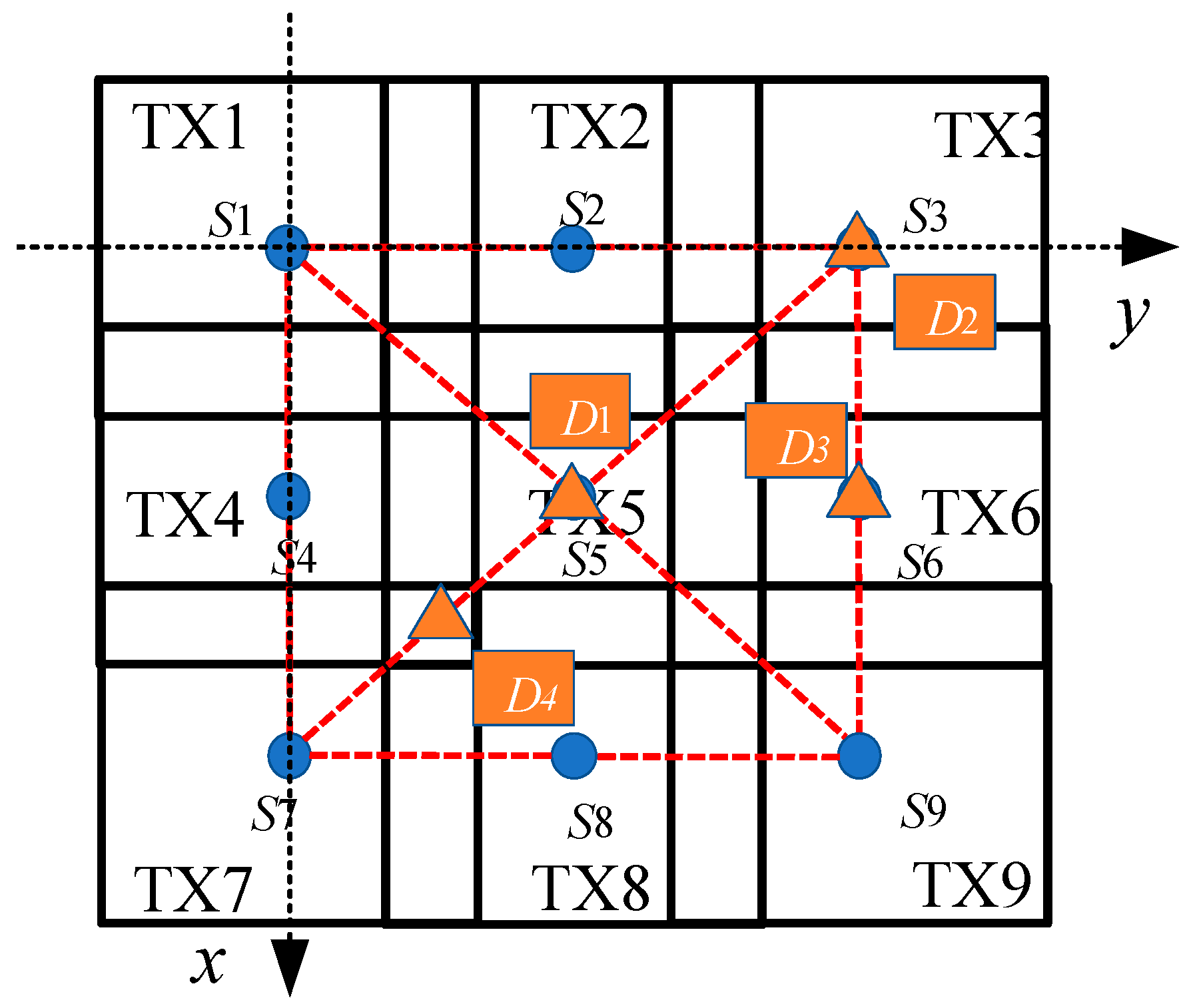
Figure 10 is the schematic diagram of receiver coil position detection. The centre point of each primary side transmitter coil is S1, S2, S3, S4, and the coordinate origin is the centre point of the working area. To avoid losing generality, select the representative position of the centre point of the receiver coil in the detection area, the centre point of the working area D1, the side vertex D2, the side midpoint D3, and the diagonal quarter point D4.
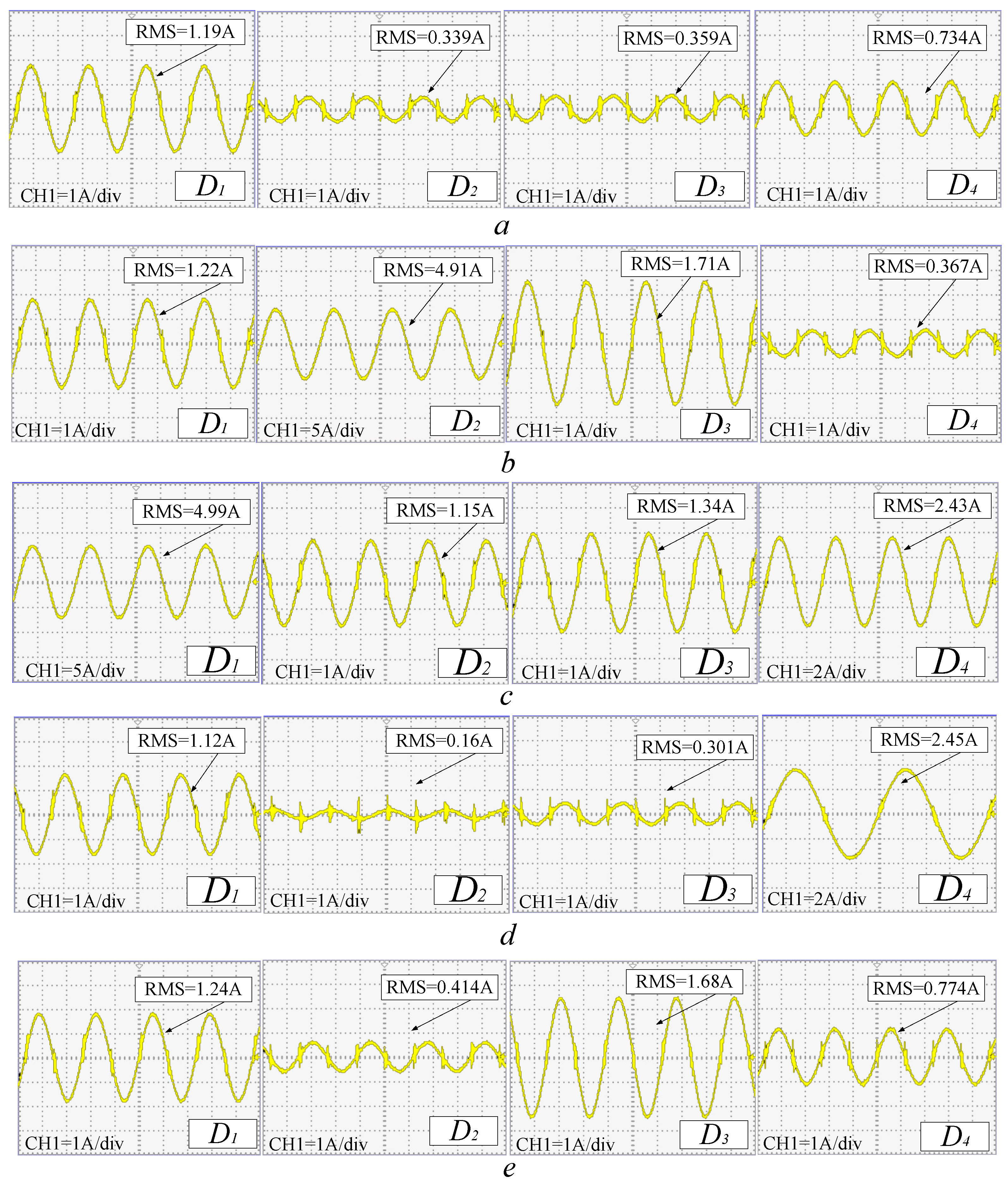
The current waveforms of the primary side transmitter coil 1,3,5,7,9 and the receiver coil in different positions of the array multi-transmitter WPT system are shown in
Figure 12. The practical value of the receiver coil current is brought into the equation (6). The mutual inductance values of the secondary coil and the transmitter coils 1,3,5,7, and 9 can be obtained. Due to the measurement error and the difference in coil parameters, when the receiver coil is located at D1, the corresponding receiver coil current parameters are different when the transmitter coil is turned on 1,3,7 and 9, respectively. But they are consistent. The calculation results agree with the mutual inductance values of the receiver coil and each transmitter coil obtained by Maxwell.
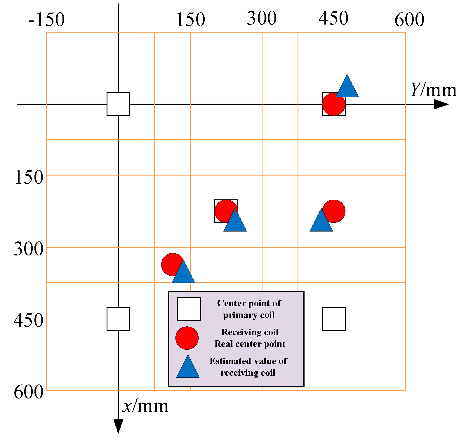
The receiver coil current can effectively obtain the mutual inductance between the receiver and the transmitter coils. The next step is to verify the algorithm for detecting the position of the receiver coil. Five target points in
Figure 12 are selected to conduct the original transmitter coil in turn, and the practical value of the receiver coil current is obtained. Put the practical value of the receiving coil into the formula (6). The mutual inductance can be obtained between the receiver and transmitter coils at different positions. According to formula (11), the offset distance corresponding to the mutual inductance value between transmitter and receiver coils can be obtained. For different transmitter and receiver coils, the coordinates of the centre point of the receiver coil are solved by the mutual inductance mathematical model equation (20) proposed in this paper. In addition, by measuring the current of the receiving coil at different positions 10 times, the RMSE of the position recognition algorithm is calculated to measure the effectiveness and accuracy of the algorithm.
It can be seen from
Table 3 that the RMSE of different target position points is slightly different, but the difference is not significant, indicating that the position detection method in this paper can obtain the position of the receiver coil in the effective detection area. The estimated RMSE of the target points
D3 and
D4 are greater than those of
D1 and
D2. The target point
D1 and
D2 are located at the centre of transmitter 5 and transmitter 3, and the interference of the detection algorithm is slight. The target points
D3 and
D4 are greatly disturbed by the system. Finally, the experimental prototype of the array multi-transmitter WPT system is built, and the current of the receiver coil is obtained under different working conditions when the transmitter coil and the receiving coil are opened to different positions of the working plane. In addition, the receiver position identification method of the array multi-transmitter wireless power transfer system proposed in this paper has also been verified. Due to the difference between the compensation network and the transmitter coil parameters, as well as the difference with the design parameters, the RMSE of different target points will be different, but they are all within a reasonable range. It can be seen from
Figure 13 that the difference between the detection results of each target point and the accurate coordinates is insignificant. The experimental results show the effectiveness of the receiver position detection method proposed in this paper.
5. Conclusion
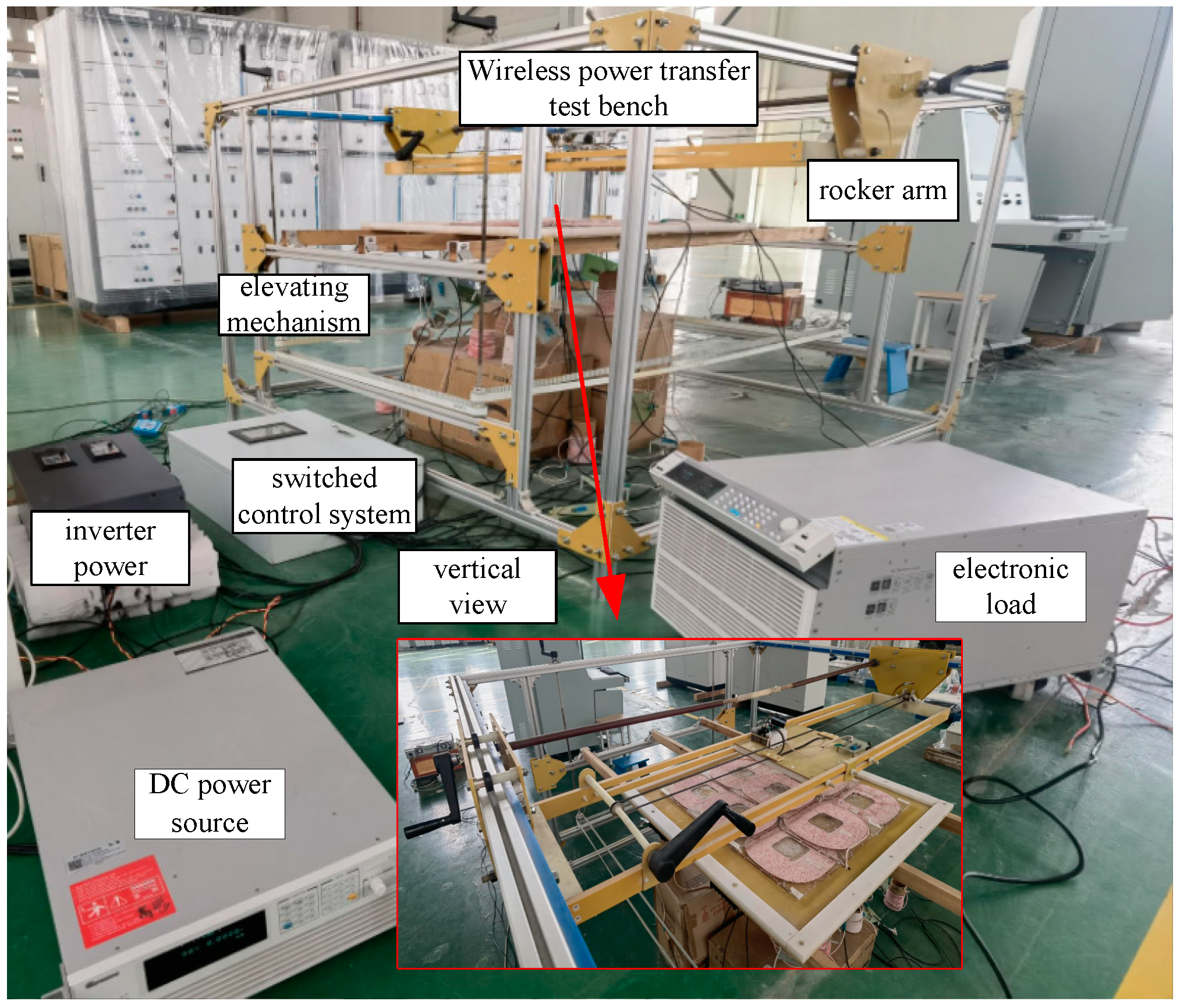
This paper proposes a method of detecting the position of the receiver coil on the X-Y plane based on the secondary coil current. The current of the receiver coil determines the offset distance between the receiver coil and a single transmitter coil. The mathematical model of mutual inductance between the receiver coil and the transmitter coil at different positions on the working plane is obtained by polynomial approximation, which can realize the positioning of the receiver coil at different positions on the working plane in the array multi-transmitter WPT system. Finally, an array multi-transmitter WPT system prototype is constructed. By adjusting the different positions of the receiver coil on the working plane through the rocker arm mechanism, the other transmitter coils are opened to obtain the current of the corresponding receiver coil. The current value is substituted into the position detection method of the receiver coil to estimate the position of the receiving coil and compare it with the actual position of the receiver coil. The correctness of the proposed receiver position identification method for an array multi-transmitter wireless power transfer system is verified.
Author Contributions
Conceptualization, Da Li. and Xusheng Wu.; methodology, Wei Gao.; software, formal analysis, Jianxin Gao. All authors have read and agreed to the published version of the manuscript.
Funding
This research was funded by National Natural Science Foundation of China, grant number 51807197.
Data Availability Statement
The data presented in this study are available on request from the corresponding author. The data are not publicly available due to other related papers are currently being submitted for submission.
Conflicts of Interest
The authors declare no conflict of interest.
References
- N. Oshimoto, K. Sakuma and N. Sekiya. Improvement in Power Transmission Efficiency of Wireless Power Transfer System Using Superconducting Intermediate Coil. IEEE Transactions on Applied Superconductivity,2023. 33,5, 1-4. [CrossRef]
- S. Azhari et al. Integration of Wireless Power Transfer Technology With Hierarchical Multiwalled Carbon Nanotubes-Polydimethylsiloxane Piezo-Responsive Pressure Sensor for Remote Force Measurement. IEEE Sensors Journal, 2023,23,7, 7902-7909. [CrossRef]
- T. Li et al. Analysis and Design of Rotary Wireless Power Transfer System With Dual-Coupled XLC/S Compensation Topology. IEEE Transactions on Industry Applications, 2023,59,2, 2639-2649. [CrossRef]
- Wei Zhang. Design for Efficiency Optimization and Voltage Controllability of Series–Series Compensated Inductive Power Transfer Systems’, IEEE Transactions on Power Electronics, 2014, 29, 1, 191-200. [CrossRef]
- Wang Y, Lin F, Yang Z. Coils layout optimization of dynamic wireless power transfer system to realize output voltage stable’, International Power Electronics Conference. 2018,3495–3500. [CrossRef]
- Mukhatov A, Bagheri M, Dehghanian P. Reduction of Output Power Pulsations for Electric Vehicles by Changing Distances between Transmitter Coils. 2018 7th International Conference on Renewable Energy Research and Applications (ICRERA). 2018, 307–312. [CrossRef]
- Li Y, Hu J, Tianren L. A New Coil Structure and Its Optimization Design With Constant Output Voltage and Constant Output Current for Electric Vehicle Dynamic Wireless Charging’, IEEE Transactions on Industrial Informatics, 2019,15,9,5244-5256. [CrossRef]
- Lu F, Zhang H, Hofmann H. A Dynamic Charging System With Reduced Output Power Pulsation for Electric Vehicles’, IEEE Transactions on Industrial Electronics, 2016, 63,10,6580-6590. [CrossRef]
- Liu H, Tan L, Huang X.:’ Power Stabilization based on Switching Control of Segmented Transmitter Coils for Multi Loads in Static-Dynamic Hybrid Wireless Charging System at Traffic Lights’, Energies, 2019,12,4,607-626. [CrossRef]
- Lu Weiguo, Chen Weiming. Multi-Load Constant Voltage Design for Multi-Load and Multi-Coil Wireless Power Transfer System. TRANSACTIONS OF CHINA ELECTROTECHNICAL SOCIETY, 2019,34,06,1137-1147.
- Liu F, Yang Y, Ding Z. Eliminating cross interference between multiple receivers to achieve targeted power distribution for a multi-frequency multi- load MCR WPT system. IET Power Electronics, 2018,11,8, 1321-1328. [CrossRef]
- Pantic Z, Lee K, Lukic S M. ‘Multifrequency Inductive Power Transfer. IEEE Transactions on Power Electronics, 2014,29,11,5995-6005. [CrossRef]
- Pantic Z, Lee K, Lukic S M. ‘Receivers for Multifrequency Wireless Power Transfer: Design for Minimum Interference’,. IEEE Journal of Emerging and Selected Topics in Power Electronics, 2015,3,1,234-241. [CrossRef]
- Jack. K, Dong. K, Yang. P. Analysis of Capacitive Impedance Matching Networks for Simultaneous Wireless Power Transfer to Multiple Devices. IEEE Transactions on Industrial Electronics, 2015,62.5,2807-2813. [CrossRef]
- Yang Jin-ming, Guan Fang. Anti-interference Control of Multiple Receiving Coils Wireless Power Transfer System [J]. Power Elecreonics ,2019,53,02,40-43.
- Duong Q T, Okada M. Analysis of reactance compensation for eliminating cross-coupling in multiple-receiver inductive power transfer. 2017 11th European Conference on Antennas and Propagation (EUCAP), 2017,492-495. [CrossRef]
- Rui. M, Yang. L, Yi. L, et al. An Active-Rectifier-Based Maximum Efficiency Tracking Method Using an Additional Measurement Coil for Wireless Power Transfer. IEEE Transactions on Power Electronics, 2018,33,1,716-728.
- Diekhans T.A Dual-Side Controlled Inductive Power Transfer System Optimized for Large Coupling Factor Variations and Partial Load. IEEE Transactions on Power Electronics, 2015,30,11,6320-6328.
- Karam Hwang. Ferrite Position Identification System Operating With Wireless Power Transfer for Intelligent Train Position Detection. IEEE Transactions Intelligent Transportation Systems, 2019, 20, 1, 374-382. [CrossRef]
- Li X , Hu J , Wang H ,et al. A New Coupling Structure and Position Detection Method for Segmented Control Dynamic Wireless Power Transfer Systems. IEEE Transactions on Power Electronics, 2020, 35,7,6741-6745.
- V. Jiwariyavej, T. Imura and Y. Hori. Coupling Coefficients Estimation of Wireless Power Transfer System via Magnetic Resonance Coupling Using Information From Either Side of the System. IEEE Journal of Emerging & Selected Topics in Power Electronics, 2015,3,1,191-200. [CrossRef]
- J. Shin. Design and Implementation of Shaped Magnetic-Resonance-Based Wireless Power Transfer System for Roadway-Powered Moving Electric Vehicles. IEEE Transactions on Industrial Electronics, 2014,61,3,1179-1192. [CrossRef]
- Moisés Rivas-López, Gomez-Sanchez C A. Rivera-Castillo J. Vehicle detection using an infrared light emitter and a photodiode as visualization system. 2015 IEEE 24th International Symposium on Industrial Electronics (ISIE). IEEE, 2015.972-975.
- Medina C, Segura, José, De la Torre, angel. Ultrasound Indoor Positioning System Based on a Low-Power Wireless Sensor Network Providing Sub-Centimeter Accuracy. Sensors, 2013, 13, (3),:3501-3526. [CrossRef]
- Birrell S A, Wilson D, Yang C P. How driver behaviour and parking alignment affects inductive charging systems for electric vehicles. Transportation Research Part C: Emerging Technologies, 2015, 721-731. [CrossRef]
- V. Jiwariyavej, T. Imura and Y. Hori. Coupling Coefficients Estimation of Wireless Power Transfer System via Magnetic Resonance Coupling Using Information From Either Side of the System. IEEE Journal of Emerging & Selected Topics in Power Electronics, 2015,3,1,191-200. [CrossRef]
- Deng Q, Liu J, Czarkowski D. Edge Position Detection of On-line Charged Vehicles With Segmental Wireless Power Supply’, IEEE Transactions on Vehicular Technology, 2017.66, 5,3610–3621.
- Kamineni A, Neath M J, Zaheer A. Interoperable EV Detection for Dynamic Wireless Charging With Existing Hardware and Free Resonance. IEEE Transactions on Transportation Electrification, 2016, 3.2,370-379. [CrossRef]
- Xiaofei Li. A New Coupling Structure and Position Detection Method for Segmented Control Dynamic Wireless Power Transfer Systems. IEEE Transactions on Power Electronics, 2020, 35,7,6741-6745. [CrossRef]
- H. Shen, P. Tan, B. Song, and B. Zhang. Receiver Position Estimation Method for Multi-transmitter WPT System Based on Machine Learning. IEEE Transactions on Industry Applications, 2022,58, 1, 1231-1241.
- Jiang Q , Qin Y , Zhao Y. A Receiver Position Estimation Scheme in Wireless Power Transfer System. IEEE International Conference on Consumer Electronics (ICCE), 2018.978-981.
- W. Han, K. T. Chau, C. Jiang and W. Liu. Accurate Position Detection in Wireless Power Transfer Using Magneto resistive Sensors for Implant Applications. IEEE Transactions on Magnetics, 2018,54,11, 1-5.
- J. Li, F. Yin, L. Wang, and D. Yang. Electromagnetic Induction Position Sensor Applied to Anti-Misalignment Wireless Charging for UAVs. IEEE Sensors Journal,2020, 20 ,1, 515-524. [CrossRef]
- Z. Liu, L. Wang. Receiver Position Identification Method of Wireless Power Transfer System Based on Magnetic Integration Inductance. IEEE Transactions on Industry Applications, 2022, 58,1, 1136-1145. [CrossRef]
- N. Kang, Y. Shao, M. Liu and C. Ma. Analysis and Implementation of 3D Magnetic Field Shaping via a 2D Planar Transmitting Coil Array. IEEE Transactions on Power Electronics, 2022, 37, 1, 1172-1184. [CrossRef]
- Fu, Minfan. Efficiency and Optimal Loads Analysis for Multiple-Receiver Wireless Power Transfer Systems’ IEEE Transactions on Microwave Theory and Techniques, 2015, 63,3,pp, 801-812.
|
Disclaimer/Publisher’s Note: The statements, opinions and data contained in all publications are solely those of the individual author(s) and contributor(s) and not of MDPI and/or the editor(s). MDPI and/or the editor(s) disclaim responsibility for any injury to people or property resulting from any ideas, methods, instructions or products referred to in the content. |
© 2023 by the authors. Licensee MDPI, Basel, Switzerland. This article is an open access article distributed under the terms and conditions of the Creative Commons Attribution (CC BY) license (http://creativecommons.org/licenses/by/4.0/).
