
Submitted:
12 September 2023
Posted:
14 September 2023
You are already at the latest version
Abstract
The purpose of the investigation was to determine the relationship between rotary kiln liner loss and steel structure ovality. As measurement apparatus, a terrestrial laser scanner was used. The interior and exterior of the rotary kiln were measured. The primary focus object was inner-lining loss and the geometric characteristics of cylindrical shells. The research uncovered significant disparities in inner lining loss between sections. A correlation was found between ovality and elimination of inner lining. Due to the hypothesis of constant inner linig loss from the middle of the rotary kiln, the investigation found that the loss of brick lining was less than the value reported from the boreholes. The study offers significant information on maintenance and repair strategies for rotary kilns, which have the potential to increase their efficiency and useful life.
Keywords:
laser scanning
; rotary kiln
; geometry analysis
1. Introduction
A rotary kiln is a large cylindrical industrial furnace that is used for drying, calcination, and chemical reactions, among other applications. Typically, it consists of a steel shell lined with refractory materials to withstand extreme temperatures. Slowly and continuously rotating rotary kilns allow materials to be processed or heated as they move along the length of the kiln. In industries such as cement production, lime production, and chemical processing, they are commonly used for clinker production, mineral roasting, and waste incineration. Figure 1 showed measured rotary kiln with terrestrial laser scanner.
A rotary kiln usually has a cylindrical shell, a riding ring, pads for the riding ring, thrust rollers, support rollers, and a method for turning the ring. Scheme is showed on Figure 2 Inside the shell, there is often a refractory lining that saves the shell from the high temperatures created by the operation of the kiln. Depending on what the rotating kiln is used for, it may also have other parts, such as a cooler or a preheater.
Rotary kiln shape features
- Shape: The shape of the kiln as a whole, including any changes from a perfect cylinder.
- Size: The length and width of the kiln, as well as the depth.
- Symmetry: The degree to which the kiln is symmetrical, including any differences from perfect symmetry.
- Wear and Tear: The amount of wear and tear on the surface of the kiln, including any places where there is a lot of damage or wear.
- Ovality: The amount to which the cross-section of the kiln is circular or elliptical.
- Displacement: The amount that the kiln moves or shifts.
- Twist: The amount that the shaft of the kiln is turned.
- Deformations: Any changes to the surface of the kiln.
The cylindrical shell of a rotary kiln can be made of a number of different materials depending on what it will be used for and how it will be run. Carbon steel, stainless steel, refractory bricks, and cast refractory are all products that are often used. The focus is the cylindrical shell of the rotary furnace and its geometric features, such as the diameters of the parts that are welded together and how oval or round they are.
The deformation of the rotary kiln shell can cause a number of problems, such as uneven wear of the refractory lining, bigger mechanical stress on the shell and support rollers, and a decline in the kiln’s efficiency and ability to make things. Deformation can also cause the kiln to be out of place, which wastes energy and reduces the quality of the products. So keeping an eye on and figuring out how the rotary kiln shell is changing is important for making sure the kiln works well and lasts a long time.[1]
Rotary kiln controls
- Checking the refractory lining for damage or wear that could cause the shell to get too hot and change shape.
- Checking for wear or misalignment in the riding ring and support wheels, which can cause the shell to be loaded unevenly and change shape.
- Checking for wear or damage on the thrust rollers and thrust bearings, which can cause axial thrust loads that can cause the shell to bend.
- Making sure the drive system is aligned and working right, which can affect how the shell is loaded and where it is placed
- Checking the shell for signs of cracks, deformation, or other damage, and fixing or replacing it as needed.
- Keeping an eye on the kiln’s temperature and other conditions and making changes as needed to keep the shell from getting damaged.
There are several ways to measure the ovality of a rotary oven. Shelltester is a tool used to measure how oval rotary kiln shells are. It does this by taking a picture of the drum’s 3D surface profile, which gives a detailed picture of the drum’s surface. It works with the help of a set of sensors that are put around the kiln. At different points around the shell’s diameter, the sensors measure how far away the shell is from the sensors. This lets the ovalness of the shell be calculated. [1,3]
High temperature around a total station, scanning the operating rotary kiln, affects the accuracy of the measurement. Refraction must be taken into account by using a thermal camera to measure the air temperature. [20]
The total station can be used to find out how straight the shell’s rotation axis is, where the bearing rollers and tires are in relation to each other, and where their rotation axes are. When the rotating kiln is cold, it is possible to get better results.[5]
Laser scanning is a common way to measure complicated things. Using laser scanning technology, a large number of 3D data points are collected, and then this information is used to make a detailed map of the surface of the building. It is possible to use point clouds to determine displacement, curvature, spin, and so on. [4]
Measuring with a terrestrial laser scanner (TLS) is faster than with a total station, but it takes longer to process the data. For further research, it’s important to get rid of all (redundant points/data).[10] By comparing two point clouds, it is possible to detect structural changes in time.[6,7]
Some studies used segmentation of raw point clouds to cut down on the amount of time it took to process. Point cloud is broken up into different shapes, like rotary rings, circular shells, and others. Geometric factors like shape, size, symmetry, ovality, displacement, curvature, and twist can be estimated by using segmented point clouds.[10]
Laser tracker and high-precision total station is mostly used for rotary kiln drive alignment, which includes the position of the furnace axis, center-to-center distance of the gears of the crown pair, radial and axial beats of the ring gear, etc.[7]
Another system made up of a laser system, a hall sensor, and a magnet is used to figure out the eccentricity of the radius, the deformation of the surface of the cylinder, and the eccentricity of the center of the cross section from the rotary kiln axis. Magnet and Hall sensor are placed on meshing gear to make pulse signal for start and stop laser data acquisition. Laser data are used to determine the coordinates of 3D points for further research. [11]
After the annual lime firing process, the loss of the lining inside the rotary lime kiln was recorded. The people in charge of a rotary kiln have to check the loss every year and figure out where fixes need to be made. Each year, borehole readings show how much of the lining has been lost. The inner lining is drilled every two meters along the 42 meters closest to the fire flame, which are the parts of the kiln that get the most wear. The drill bit is pushed through the brick until it hits the steel structure. The height of the rest of the inner covering is then decided. The loss can only be calculated at the point of drilling by comparing the ideal inner lining to the actual inner lining. Laser scanning is the best way to get information from the inside of a rotary kiln while limiting the number of useless cement points. [14]
Measuring methods
- Total station measurement: measuring the size of the kiln with an electronic surveying tool.
- Laser scanning: using laser scanners to take point cloud data of the kiln’s surface and then processing the data to make a 3D model of the kiln.
- Terrestrial photogrammetry: A 3D model of the kiln is made from a collection of high-resolution photos taken from different angles.
- Infrared thermography: Using thermal imaging cameras to find areas of wear or damage on the surface of the oven where the temperature changes.
- Ultrasonic testing: Using ultrasonic sensors to measure the thickness of the kiln’s shell and find places where it is getting thinner or eroding.
- Vibration analysis: Using sensors to watch the kiln’s vibration patterns and find any strange moves or vibrations that could hint at a possible problem.
During a rotary kiln shutdown, point clouds were collected. Ladle refractory linings used in the steel industry can be checked for gaps and cracks with a special laser scanner. [18]
We use the laser scanning method to figure out how much of the inner layer has been lost. Every year, the internal lining of the rotary kiln is inspected and repaired as necessary. The inspection is performed by piercing the inner lining with a drill and then measuring the remaining brick’s depth. Unfortunately, since the drilling is only performed in a single line along the entire length of the rotary kiln, measurements cannot be taken over the entire surface area of the rotary kiln. The laser scanner is used to measure the whole interior area and figure out how much loss there is. There are different ways to figure out the cost. The first option is based on the difference between the point cloud of the inner lining and the point cloud of the outer steel structure. To do this, the plans must show the thickness of the outer steel structure. The second choice is to make a perfect model of the inner lining and figure out how different it is from the actual point cloud.
2. Materials and Methods
The measured object is a rotary lime kiln in the paper industry. The length of the kiln is 97 meters, and the steel frame is 1.82 meters in diameter. The kiln is about 3 meters above the ground and is held up by four pedestals. There are two pedestals at each end of the furnace and two that are evenly spread along its length. On the two substations in the middle, there are motors that can be used to turn the furnace. Scheme is showed on Figure 2.
The burner itself is made of steel and has a lining inside. Most of the steel frame of the furnace is 22 mm thick, and the riding ring has reinforcements that are 30 to 50 mm thick.
The inner lining is split into several parts based on the process being done: the burning zone, the intermediate zone, the heating zone, and the feeding zone (Figure 3). Most of the wear, or loss, happens in the burning zone, where the high temperatures for lime firing break down the brick walls. So, the inner lining gets thicker in the places where there is more wear than in other places. At the same time, the covering from the burning zone to the heating zone is made of two different materials to ensure sufficient insulation.
A Leica RTC360 laser scanner was used to measure the whole rotating kiln Figure 4. The Leica RTC360 is a highly accurate laser scanning system used for capturing 3D measurements of objects, including rotary kilns. With an accuracy of up to ±2mm, [16] it provides precise and reliable measurement results. The system’s advanced laser scanning technology and intuitive software enable efficient data acquisition and analysis. It offers multiple scanning modes and incorporates positioning technology for accurate registration of data.
Workflow
- Scanning rotary kiln exterior
- Scanning rotary kiln interior with spherical targets
- Scanning lime firing area to connect interior and exterior
- Registration of scans in Leica Cyclone Register360
- Clean scan from unnecessities
- Export separately interior and exterior scans
- Estimating axis of rotary kiln by fitting cylinder on exterior scans
- Modeling perfect state of inner lining
- Estimating lining loss by comparing model of perfect state with interior scans
The steel frame on the outside and the brick walls on the inside were both measured. The connection between the interior and exterior was determined through the kiln entrance in the lime firing area. Two accessible spaces were used in the measurement to sufficiently register the interior. To keep a big overlap for the cloud2cloud registration method, maximum distance between positions was 5m. During the readings, spherical targets were used to check and make sure that the registration was correct. Most of the time, the spherical targets were used to scan the inner lining to avoid misregistration, the targets were spread out across the bottom of the rotating kiln in a way that was not symmetrical. During the scans, the kiln was not being used, and most of the lime was cleaned off the inside of the kiln. The rest of the lime was left on the bottom of the kiln, where it stuck strongly.
Moving people and other unwanted things were taken out of the point cloud that was left, leaving only the point cloud of the lime oven. The cloud was split into two datasets: an outer one that shows the steel frame and an inner one that shows the brick walls.
Two approaches were taken in order to calculate lining loss. The first step was to determine the distance that separated the inner and outer cloud points. This distance determined the thickness of the entire pen structure, which encompassed the steel framework, the first and second layers of brick lining, and the expansion that occurred between the layers. For this reason, it is essential to have a precise understanding of the thickness of the steel structure in order to calculate the lining loss. The expansion that occurs between the layers also has an effect on the final result.
The second approach is one that involves a little bit more work. In order to calculate the amount of loss, it is necessary to first construct a model based on the inner lining in its optimal state. This model will then be compared to the point cloud that represents the inner part. Because of this, it is necessary to identify the axis of the rotary kiln along which the ideal state model will be positioned in order to complete the process. The ambiguity on the abraded and deformed surface of the brick lining prevents the determination of the rotary kiln axis from being made using the point cloud of the inner lining. This is because the rotary kiln was built with bricks. Axis determination can be performed on the outer steel structure. For the rotary kiln to function as it should, the steel structure must be manufactured with a high degree of precision to ensure circularity and symmetry. The axis of the rotary kiln was located by employing the RANSAC method of detecting primitive objects within the point cloud that is a part of the CloudCompare software. The radius range of the cylinder was defined to be 1.82 meters +/- 2 centimeters so that it would be easier to detect. The axis of this structure corresponds to the axis of the rotary kiln. A model of the ideal condition was modeled according to the determined axis and the knowledge of the radius of the kiln interior from the composition of the brick lining in order to determine the loss of the inner lining. This was accomplished by modeling a model of the ideal condition. The lining loss was calculated by comparing the ideal model to the measured point cloud of the rotary kiln’s interior. This allowed for the identification of the lining loss.
The data that were collected can be used to estimate other physical features of the rotary kiln for further analysis:
- Rotary kiln ovality analysis
- Radius difference along rotary kiln
- Centrality of rotary kiln steel strip
- Material loss of riding rings
- Correlation of inner lining loss and ovality
3. Results
3.1. Loss of inner lining
The loss of the interior lining was determined by measuring the difference between the ideal, undamaged condition and the actual, measured condition using a laser scanner. The initial hypothesis was that the interior lining of the rotary kiln’s perpendicular section wore evenly. Greater wear occurs close to the flame, whereas the risk of wear decreases with distance. The majority of lime has been removed from the interior of the kiln. Unfortunately, it was not possible to remove all of the residue, so lime remains on the bottom of the kiln and in areas where it has adhered. In order to obtain optimal results for comparing the laser scanning procedure with boreholes, the loss was determined statistically within a perpendicular section. By stationing, the rotary kiln was divided into dozens of one-meter sections. The median of the decline values in a given section was used to define the decline from the difference model. The section’s utmost value defined the loss in the joint between the bricks. On the other hand, the minimum value consisted of contaminated lime (Figure 5).
When the difference model and the measured numbers from the boreholes were compared, they were about the same. It was found that, after 42 meters of stationing, the managers stopped measuring liner loss and just assumed that the liners were always wearing out. But it was found that the loss of brick covering was less than what was reported from the boreholes (Figure 6 and Figure 7). Due to not cleaning the lime off the bricks well enough, the median loss went from 6 meters to 66 meters of staging. Most of the brick lining in the part from 66 meters to stopping was made of lime. At the same time, it wasn’t expected that the brick lining would show much wear along this length. Due to the high frequency of lime on the brick lining, it was not further examined from 74 m of the stationing.
The original idea that there was constant wear in the furnace’s vertical part was also shown to be wrong. Between the 42 and 46 meter of rotary kiln length, there were big differences of inner loss. At the brick joint, the loss was up to 52 mm. At the brick face, it was 35 mm, and at another spot, it was 12 mm. The big difference could be because the steel frame is oval-shaped.Figure 8
3.2. Ovality
Using a reference cylinder model, the ovality was determined. Using the RANSAC method for detecting primordial objects from the point cloud, the cylinder was determined. Prior to detection, the cloud was purged of impediments to accurate measurement. For the purpose of detection, the radius of the potential cylinder was restricted to between 1.80 and 1.84 meters. Derived from the difference between the detected cylinder and the measured point cloud, the resulting ovality was molded.Figure 9
This rotating kiln can be either -2 cm or +2 cm oval. The ovality was plowed outside of the rotating rings.Figure 10
3.3. Radius Difference
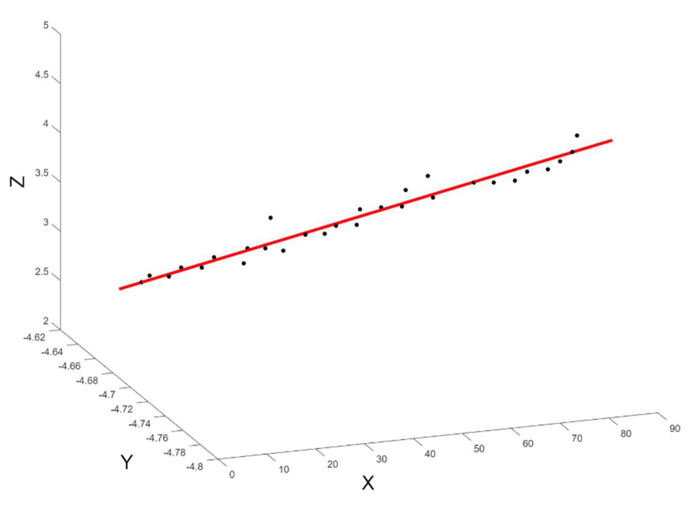
To figure out the changes in radius and centricity, the steel structure cloud was split up by the welded webs (Figure 11). There are 29 steel strips that are each a different length. The RANSAC method was used to find cylinders in each strip over a radius range of 1.80m to 1.84m. On average, the difference from the drawing radius was found to be 5mm (Figure 12). The biggest changes were found in the webs around the riding ring. Even on the drawings the steel structure is getting thicker. The position of the center of the cylinder is extracted from the detected cylinders of each steel strip. Using the least squares method, the axis of the rotary kiln was found by taking the values that were found. To figure out the centricity, the difference between each steel strip and the axis of the rotating kiln was used. The largest amount of irregularity was 18 mm (Figure 13).
3.4. Correlation of inner lining loss and ovality
The expanded cylinders of the plane in the raster were the source of the data that was used in the process of establishing whether or not there was a correlation between the loss of internal lining and the ovality of the steel structure. The values of raster ovality ranged from -5 cm to +5 cm in either direction. It was revealed that the figures for the loss of internal lining could range anywhere from ten centimeters in either direction. Because of the resolution of the difference model, neither of the rasters was free of the presence of null data. A point cloud constitutes the difference model, and each individual point stores a value corresponding to the difference.
In order to analyze the correlation, a grid of 2 cm squares and 2.1 million points was developed. Each point received a value determined by the grid that it was a part of. Following that, a filtering of the points needed to be carried out on the null data as well as for the points that had maximum values of ovality and inner lining loss. The total number of points is now 270,000 less than before.
Figure 14.
Lining Loss- upper, ovality - lower: 1) Lime that hasn’t been cleaned, 2) Corresponding welds with small lining loss, 3) Positive ovality means more lining loss, and 4) Negative ovality means less lining loss.
Figure 14.
Lining Loss- upper, ovality - lower: 1) Lime that hasn’t been cleaned, 2) Corresponding welds with small lining loss, 3) Positive ovality means more lining loss, and 4) Negative ovality means less lining loss.

Figure 15.
Correlation ovality and rotary kiln: 0-26m, 26-42m, 42-56m, 56-74m, 74-90m
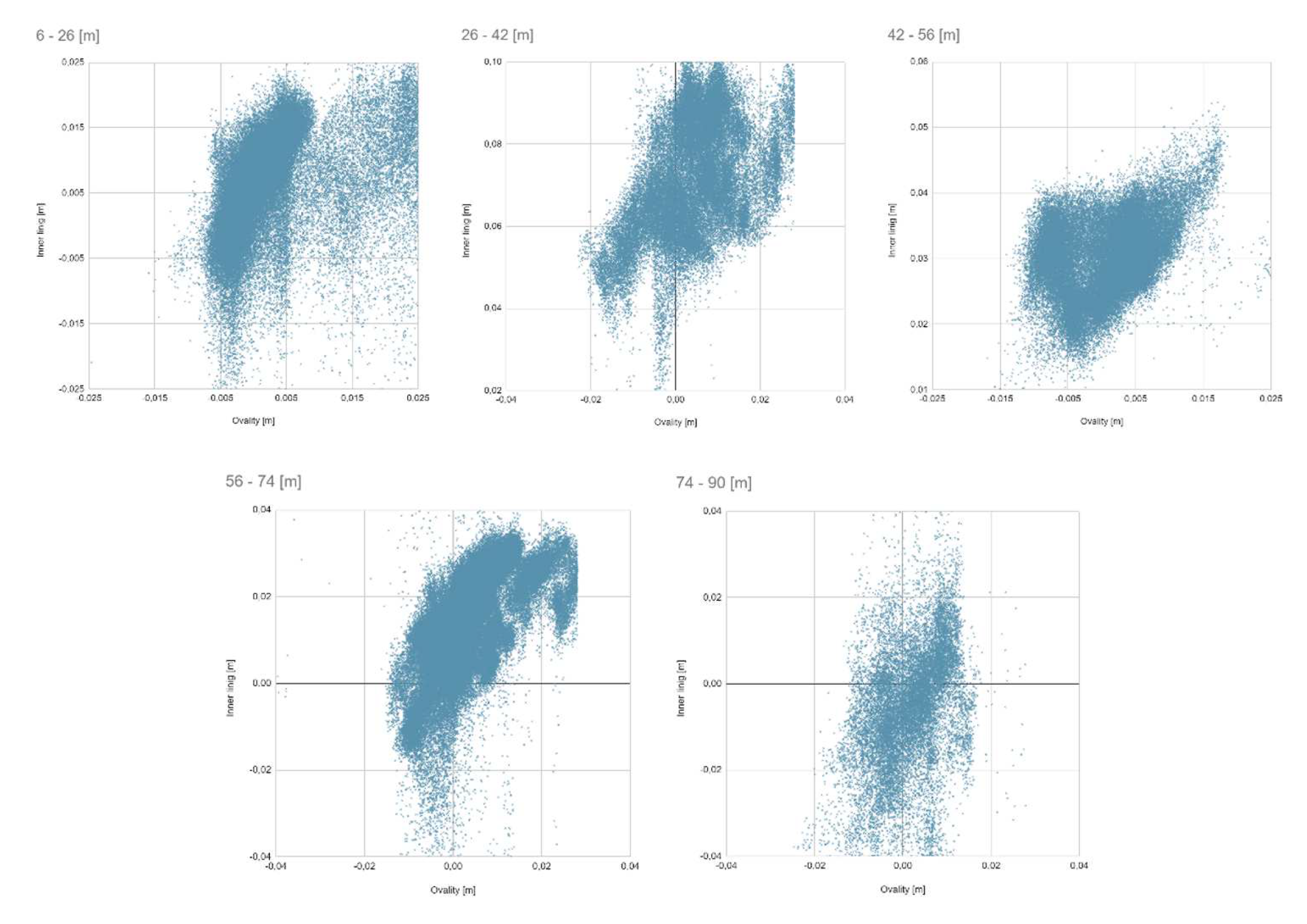

Table 1.
Pearson correlation coefficient estimated on parts of rotary kiln
| Length of rotary kiln | Pearson correlation coefficient |
|---|---|
| 6-26 m | 0.38 |
| 26-42 m | 0.47 |
| 42-56 m | 0.57 |
| 56-74 m | 0.36 |
| 74-90 m | 0.44 |
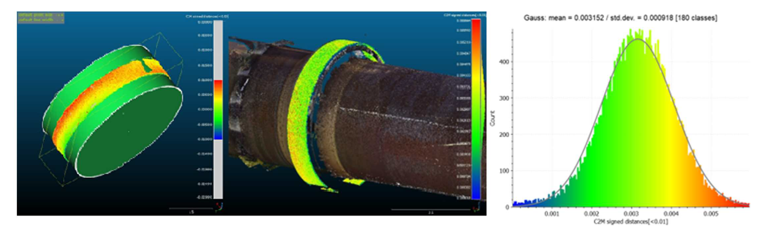
3.5. Riding ring materials loss
It is feasible to establish the level of wear that the riding rings have sustained based on the data that was measured. The preciseness of the scanner and the degree to which the shining surface of the riding ring reflects light both play a significant role in determining the outcome. The point cloud was attached to a part that contained only the riding rings in order to perform wear detection on the component. On the clipped sling, RANSAC cylinder detection was attempted, but regrettably this method was insufficient due to the low height of the discovered cylinder. The search method was unable to correctly establish the location on the point cloud of the cylinder’s axis as well as its position. The most significant inaccuracy took place during the process of determining the axis of the cylinder, which ultimately turned out to be a systematic variation on the difference model.
The Blender software was used to carry out a procedure that involved the manual alignment of a cylinder having a radius of 4.700 meters. The manual alignment produced superior outcomes in comparison to the automatic detection strategy. On the riding rings, there was no evidence of any major systematic loss. The size of the riding ring is 3 millimeters bigger than what is shown on the drawings. The values derived from the difference model have a normal distribution as the variance, and the mean error is 1mm.
Figure 16.
Imperfect RANSAC cylinder detection (left), Manual alignment of ideal cylinder (midle), Distribution of values of riding ring loss
Figure 16.
Imperfect RANSAC cylinder detection (left), Manual alignment of ideal cylinder (midle), Distribution of values of riding ring loss
4. Discussion
This article provides an evaluation of two methods, laser scanning and drilling, for estimating lining loss in rotary kilns. Laser scanning offers several advantages as a nondestructive technique. It enables comprehensive data acquisition, capturing detailed geometry of the kiln’s inner surface and facilitating precise measurements. Laser scanning is time-efficient, requires minimal setup, and eliminates the need for physical contact with the kiln, reducing safety risks. However, it does have limitations, including high costs for equipment and data processing, limited penetration depth, and susceptibility to environmental conditions like high temperatures and pollution.
On the other hand, drilling provides direct measurements of lining thickness, making it a reliable method for estimating loss. It is a cost-effective approach that utilizes basic equipment and techniques. However, drilling is a destructive method that may cause structural damage and provide limited samples, potentially underestimating the extent of lining loss.
The choice between laser scanning and drilling depends on various factors, such as project requirements, precision needed, the magnitude of lining loss, costs, schedule constraints, and kiln condition. A thorough analysis of these factors can determine the optimal method for estimating lining loss in a rotary kiln.
Furthermore, the study investigated the relationship between inner lining loss and the design of the kiln’s steel frame. The findings revealed a positive correlation, indicating that higher ovality values were associated with increased lining loss. This highlights the importance of considering structural changes when assessing the integrity of the kiln’s inner layer. The correlation coefficients ranging from 0.38 to 0.57 indicate a moderate to moderately strong positive correlation between ovality and lining loss in the studied rotary kiln. While these coefficients may not be exceptionally high, they signify a significant relationship between the variables.
5. Conclusions
The purpose of the research was to establish a relation to the ovality of the steel structure and the amount of material that was lost from the inside lining of the rotary kiln. It was determined how much of the inner lining had been lost by making a comparison between the ideal condition (one in which there was no damage) and the real condition (one that was measured using a laser scanner). According to the results of the research, the prediction that the perpendicular part of the furnace would experience consistent wear was erroneous. The investigation indicated that there were considerable variances in the amount of loss detected between sections. The joint noticed the greatest loss, which measured up to 52 millimeters, while the face of the bricks experienced a loss of 35 millimeters and 12 millimeters elsewhere. The ovality of the rotating kiln ranged from minus two centimeters to plus two centimeters and was measured outside of the rotary rings. The location of the cylinder’s center was derived from the observed cylinders of each steel strip, and the axis of the rotary kiln was located using the method that minimized the sum of the squared deviations. The eccentricity reached a peak value of 18 mm at its highest point. The ovality of the steel structure was measured using a 2cm grid that contained 2.1 million points. Each point was given a value from this grid so that the correlation between the loss of internal lining and the ovality of the steel structure could be determined. Filtering out null data and points with maximum values of ovality and loss of internal lining led to a reduction in the total number of points, which was brought down to 270,000. According to the findings of the study, there is a significant link between ovality and lining loss, with Pearson correlation coefficients ranging anywhere from 0.38 to 0.57 depending on which portion of the furnace was analyzed. The preciseness of the scanner as well as the reflectivity of the smooth, shining surface of the slider ring both have a significant impact on the final output. The study also discovered that the loss of brick lining is less than the value that was reported from the boreholes. The resulting median loss was taken from 6 meters to 66 meters of the stope due to inadequate cleaning of the brick lining from lime, which occupied the majority of the brick lining area in the section that began at 66 meters of the stope. At the same time, it was no longer anticipated that the brick lining throughout this length would show a significant amount of wear. Due to the high frequency of lime on the brick lining, the marquee could not be appraised much farther from its 74-meter vantage point. In summary, the research reveals important information on the internal lining loss of the rotary kiln and the correlation between that loss and the ovality of the steel structure. The study demonstrates both the significance of properly cleaning the brick lining from lime to produce accurate measurements and the limits of the laser scanner in identifying wear on the shining surface of the traveling ring. Both of these issues are highlighted in the study. The results of the study have the potential to be used as a foundation for developing maintenance and repair techniques for rotary kilns, which may ultimately result in greater productivity and longevity.
Author Contributions
Conceptualization, D.Z.; methodology, D.Z.; validation, D.Z. and J.V.; formal analysis, D.Z.; investigation, J.V.; resources, D.Z.; data curation, D.Z.; writing—original draft preparation, D.Z.; writing—review and editing, D.Z.; visualization, K.P.; supervision, K.P.; project administration, K.P.; funding acquisition, K.P. All authors have read and agreed to the published version of the manuscript.
Funding
This work was supported by the grants SGS23/052/OHK1/1T/11 and SGS23/050/OHK1/1T/11 funded by CTU Prague, Czech Republic.
Acknowledgments
Many thanks to the reviewers and the editor for their useful comments and suggestions.
Conflicts of Interest
The authors declare no conflict of interest. The funders had no role in the design of the study; in the collection, analyses, or interpretation of data; in the writing of the manuscript, or in the decision to publish the results.
Abbreviations
The following abbreviations are used in this manuscript:
| RANSAC | Random sample consensus |
References
- Świtalski, M. The measurement of shell’s elastic ovality as essential element of diagnostic of rotary drum’s technical state. Diagnostyka 2010, 53, 37–47. [Google Scholar]
- Krystowczyk, Z. Geometry measurements of kiln shell in dynamic conditions. Cem. Build. Mater. Rev. 2004, 16, 34–37. [Google Scholar]
- Available online: https://www.zmp.com.pl/shelltester (accessed on 6 October 2020).
- Jia, D.; Zhang, W.; Wang, Y.; Liu, Y. A New Approach for Cylindrical Steel Structure Deformation Monitoring by Dense Point Clouds. Remote Sens. 2021, 13, 2263. [Google Scholar] [CrossRef]
- Mogilny, S.; Sholomitskii, A. Precision analysis of geometric parameters for rotating machines during cold alignment. Procedia Eng. 2017, 206, 1709–1715. [Google Scholar] [CrossRef]
- Zhang, Z.; Yin, T.; Huang, X.; Zhang, F.; Zhu, Y.; Liu, W. Identification and Visualization of the Full-Ring Deformation Characteristics of a Large Stormwater Sewage and Storage Tunnel Using Terrestrial Laser Scanning Technology. Energies 2019, 12, 1304. [Google Scholar] [CrossRef]
- Site of Open Corporation Industrial Geodesy. Available online: http://promgeo.com/services/kiln (accessed on 6 October 2020).
- Ozek Makina. Available online: http://www.rotarykiln.net (accessed on 6 October 2020).
- NAK Kiln Services. Available online: https://nak-kiln.com (accessed on 6 October 2020).
- Kovanič, L.; Blišťan, P.; Zelizňaková, V.; Palková, J.; Baulovič, J. Deformation investigation of the shell of rotary kiln using terrestrial laser scanning (TLS) measurement. Metalurgija 2019, 58, 311–314. [Google Scholar]
- Zheng, K.; Zhang, Y.; Liu, L.; Zhao, C. Metoda računalnog mjerenja odstupanja ravnosti cilindra rotacijske peći. Tehnički vjesnik 2017, 24, 1297–1305. [Google Scholar] [CrossRef]
- Kovanič, Ľ.; Blistan, P.; Urban, R.; Štroner, M.; Pukanská, K.; Bartoš, K.; Palková, J. Analytical Determination of Geometric Parameters of the Rotary Kiln by Novel Approach of TLS Point Cloud Segmentation. Appl. Sci. 2020, 10, 7652. [Google Scholar] [CrossRef]
- STN EN. Eurocode 3: Design of Steel Structures. 1993. Available online: https://www.phd.eng.br/wp-content/uploads/2015/12/en.1993.1.1.2005.pdf (accessed on 23 October 2020).
- Tucci, G.; Conti, A.; Fiorini, L. Refractory Brick Lining Measurement and Monitoring in a Rotary Kiln with Terrestrial Laser Scanning. In R3 in Geomatics: Research, Results and Review: First International Workshop in memory of Prof. Raffaele Santamaria on R3 in Geomatics: Research, Results and Review, R3GEO 2019, Naples, Italy, October 10–11, 2019, Revised Selected Papers; Springer International Publishing, 2020. [Google Scholar]
- CloudCompare. Vers. 2.11 alpha. Available online: http://www.cloudcompare.org/ (accessed on 10 January 2019).
- Leica RTC360. Available online: https://leica-geosystems.com/-/media/files/leicageosystems/products/datasheets/leica-rtc360-ds.ashx?la=hu-hu&hash=3C70C6ADDEB8DCA88E48A26739B4A1A6.
- Schnabel, R.; Wahl, R.; Klein, R. Efficient RANSAC for point-cloud shape detection. Comput. Graph. Forum 2007, 26, 214–226. [Google Scholar] [CrossRef]
- Lamm, R.; Kirchhoff, S. Optimization of ladle refractory lining, gap and crack detection, lining surface temperature and sand filling of the ladle-taphole by means of a 3D-laser profile-measurement-system that is immersed in a hot ladle to evaluate the entire condition. UNITECR 2017, Proceedings 2017. Available online: http://www.unitecr2017.mundodecongresos.com/abstracts/Paper_rbofbhfxcsxhpgipoispm.pdf (accessed on 10 January 2019).
- Larsson, I.A.S. The Aerodynamics of an Iron Ore Pelletizing Rotary Kiln. Fluids 2022, 7. [Google Scholar] [CrossRef]
- Mogil’Nyj, S.G.; Sholomitskii, A.A.; Lagutina, E.K.; Sal’Nikov, V.G. The influence of refraction in geodetic measurements of rotary kilns. In 25th International Symposium on Atmospheric and Ocean Optics: Atmospheric Physics; SPIE, 2019. [Google Scholar]
- Žiga, A.; Karač, A.; Vukojević, D. Analytical and numerical stress analysis of the rotary kiln ring. Tehnički vjesnik 2013, 20, 941–946. [Google Scholar]
- Goshayeshi, H.R.; Poor, F.K. Modeling of Rotary Kiln in Cement Industry. Energy Power Eng. 2016, 8. [Google Scholar] [CrossRef]
- Saidur, R.; et al. A review on kiln system modeling. Renew. Sustain. Energy Rev. 2011, 15, 2487–2500. [Google Scholar] [CrossRef]
- Noshirvani, G.; Shirvani, M.; Askari-Mamani, J.; Nourzadeh, H. Estimation of coating thickness in a rotary kiln by using shell temperature and kiln modeling. ZKG Int. 2013, 58–71. [Google Scholar]
- Li, X.; Shen, Y.; Wang, S. Dynamic modeling and analysis of the large-scale rotary machine with multi-supporting. Shock Vibration 2011, 18, 53–62. [Google Scholar] [CrossRef]
- Xiao, Y.; Li, X.; Chen, X. General solution to kiln support reactions and multi-objective fuzzy optimization of kiln axis alignment. Struct. Multidiscip. Optim. 2008, 36, 319–327. [Google Scholar] [CrossRef]
- Dhillon, B.S. Multiaxial fatigue life prediction of kiln roller under axis line deflection. Appl. Math. Mech. 2010, 31, 205–214. [Google Scholar] [CrossRef]
- Pazand, K.; Panahi, M.S.; Pourabdoli, M. Simulating the mechanical behavior of a rotary cement kiln using artificial neural networks. Mater. Des. 2009, 30, 3468–3473. [Google Scholar] [CrossRef]
- Ramanenka, D.; Stjernberg, J.; Jonsén, P. FEM investigation of global mechanisms affecting brick lining stability in a rotary kiln in cold state. Eng. Fail. Anal. 2016, 59, 554–569. [Google Scholar] [CrossRef]
- Rusinski, E.; Stamboliska, Z.; Moczko, P. Proactive control system of condition of low-speed cement machinery. Autom. Constr. 2013, 31, 313–324. [Google Scholar] [CrossRef]
- Rahman, M.M.; Nijemeisland, M.; Wesselink, R.J.; Luding, S. Coupled CFD-DEM simulation of heat transfer and particle motion in a rotary kiln. Chem. Eng. Sci. 2014, 111, 657–671. [Google Scholar] [CrossRef]
- Khan, M.S.; Ahmad, I. CFD modeling of rotary cement kilns. Minerals Eng. 2013, 43-44, 57–63. [Google Scholar] [CrossRef]
- Zheng, K.; Liu, W.; Guo, F. Coupling heat transfer model of rotating cement kiln with accompanying evaporation-drying process. J. Therm. Sci. 2011, 20, 245–251. [Google Scholar] [CrossRef]
- Li, C.; Feng, Y.; Hu, Z.; Luo, S. Numerical simulation of the influence factors for rotary kiln in temperature field and stress field. J. Univ. Sci. Technol. Beijing 2006, 28, 446–451. [Google Scholar]
- Bui, T.; Beers, A.C.; van Helden, W.G.J.; Segers, A.J.H.; van Antwerpen, H.J.; van der Stappen, A.F. Integrating axis deviation and deformation control for large industrial rotary kilns. Control Eng. Pract. 2017, 61, 114–125. [Google Scholar] [CrossRef]
Figure 1.
Rotary kiln exterior
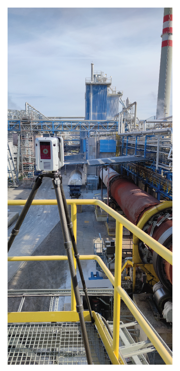
Figure 2.
Rotary kiln scheme
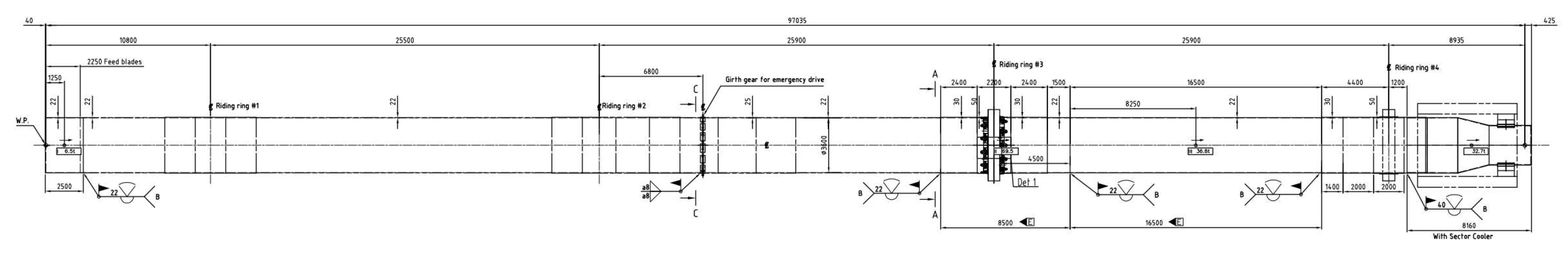
Figure 3.
Detail of composition
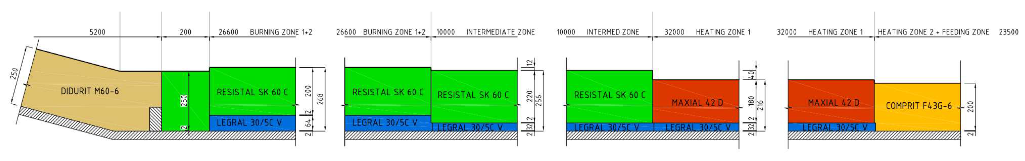
Figure 4.
Leica RTC360 inside rotary kiln
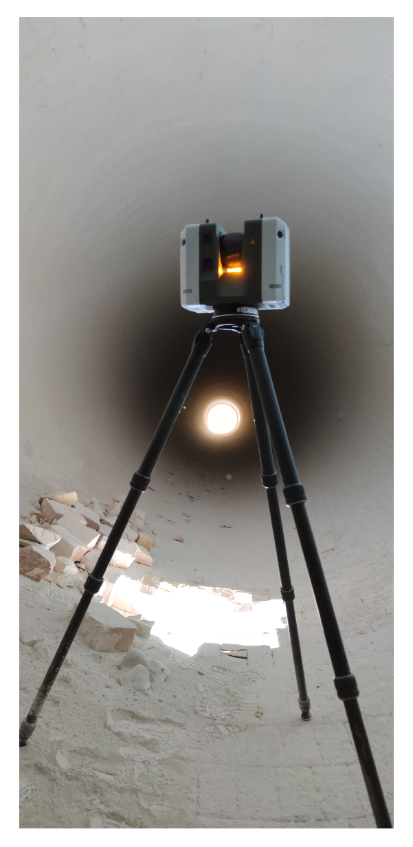
Figure 5.
Inner lining loss inside rotary kiln

Figure 6.
Comparison of lining loss by laser scan and drilling with ideal condition (purple dots - drilling, orange - median loss from scanning, red - min loss from scanning, teal - ideal state of inner lining)
Figure 6.
Comparison of lining loss by laser scan and drilling with ideal condition (purple dots - drilling, orange - median loss from scanning, red - min loss from scanning, teal - ideal state of inner lining)
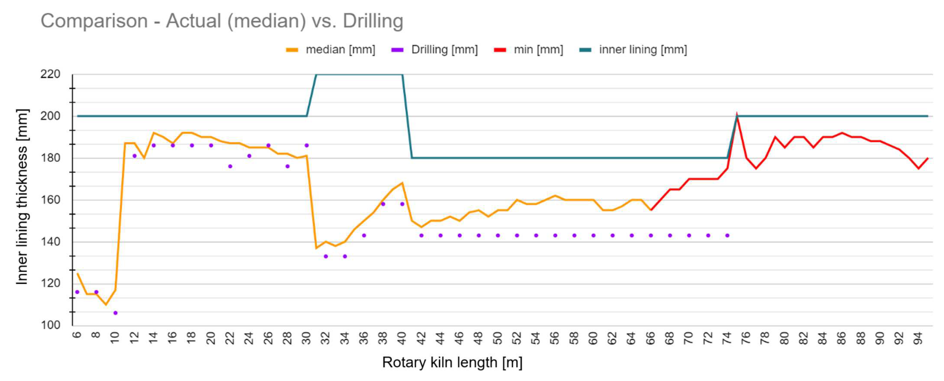
Figure 7.
Comparison max, median, min vales of lining loss by laser scan (min - red, orange - median, green - max,teal - ideal state of inner lining)
Figure 7.
Comparison max, median, min vales of lining loss by laser scan (min - red, orange - median, green - max,teal - ideal state of inner lining)
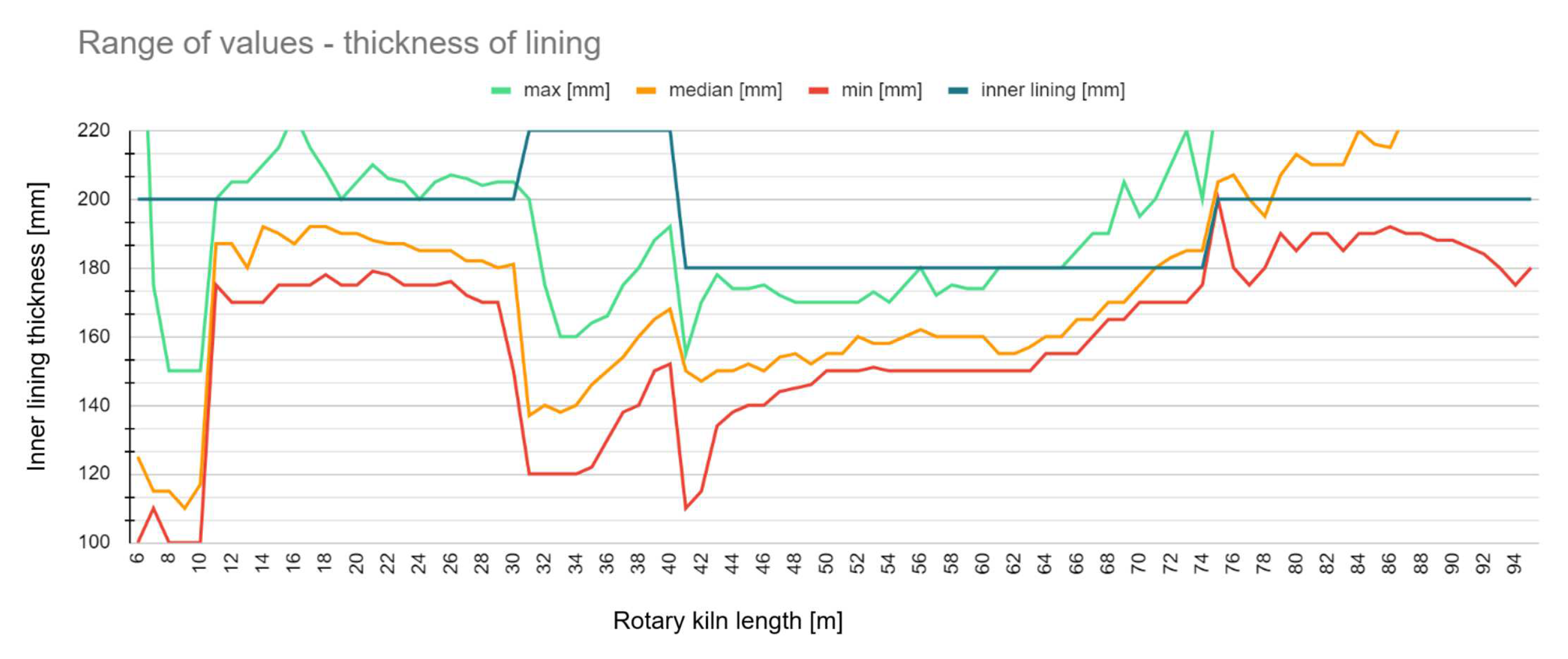
Figure 8.
Differences of wear in rotary kiln’s perpendicular section 42-46m
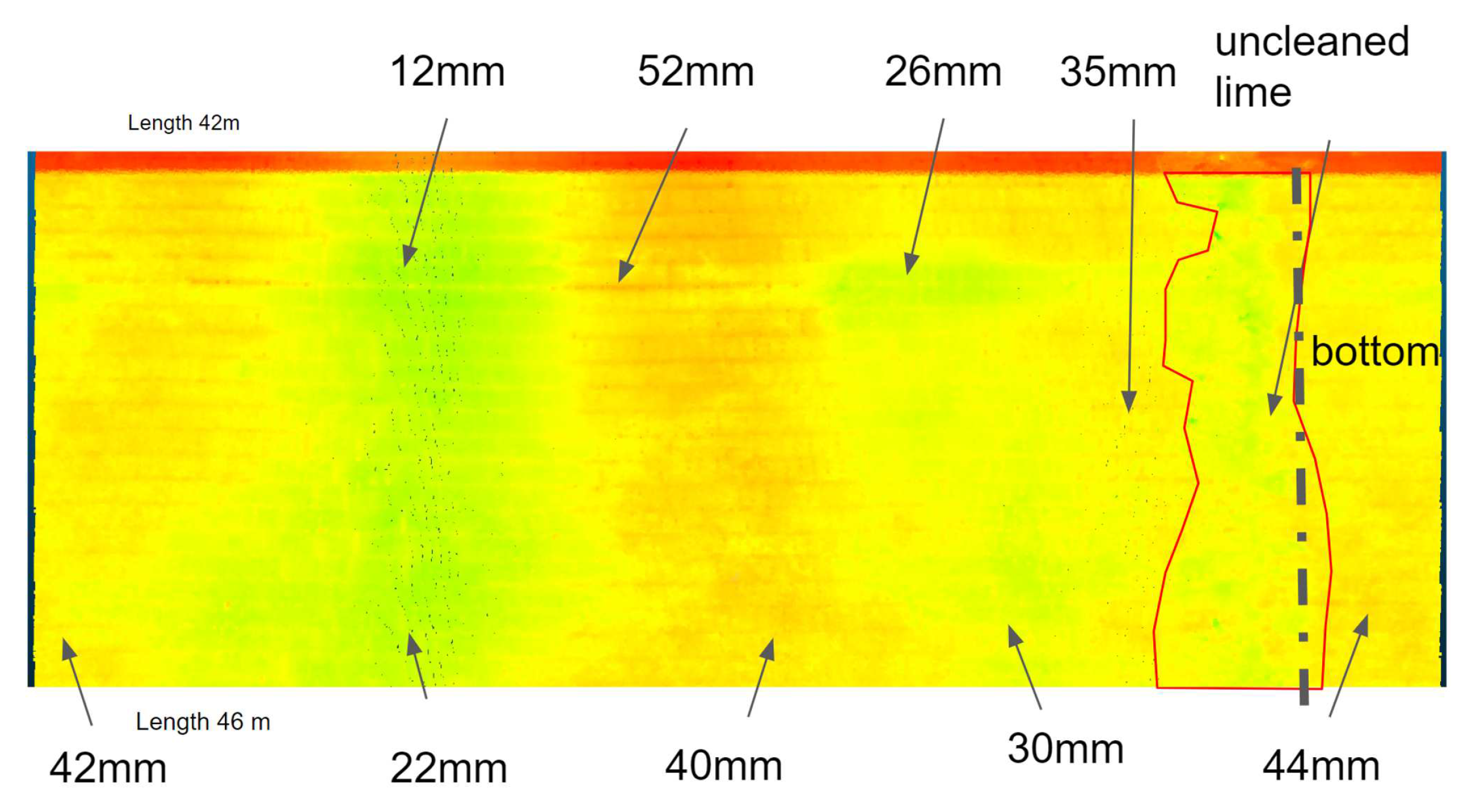
Figure 9.
Rotary kiln ovality 3D [m]

Figure 10.
Rotary kiln ovality 2D [m]
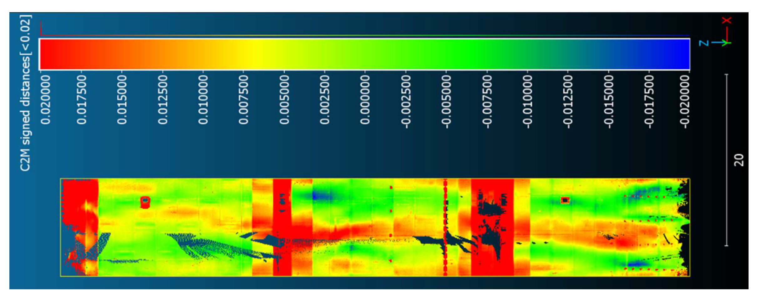
Figure 11.
Rotary kiln steel strips scheme [m]
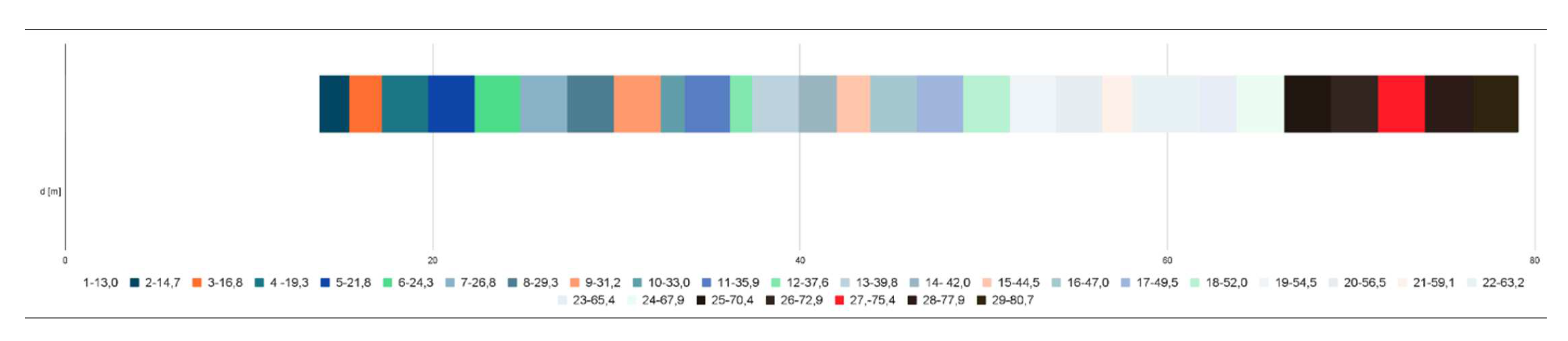
Figure 12.
Difference of steel strips radius [m]
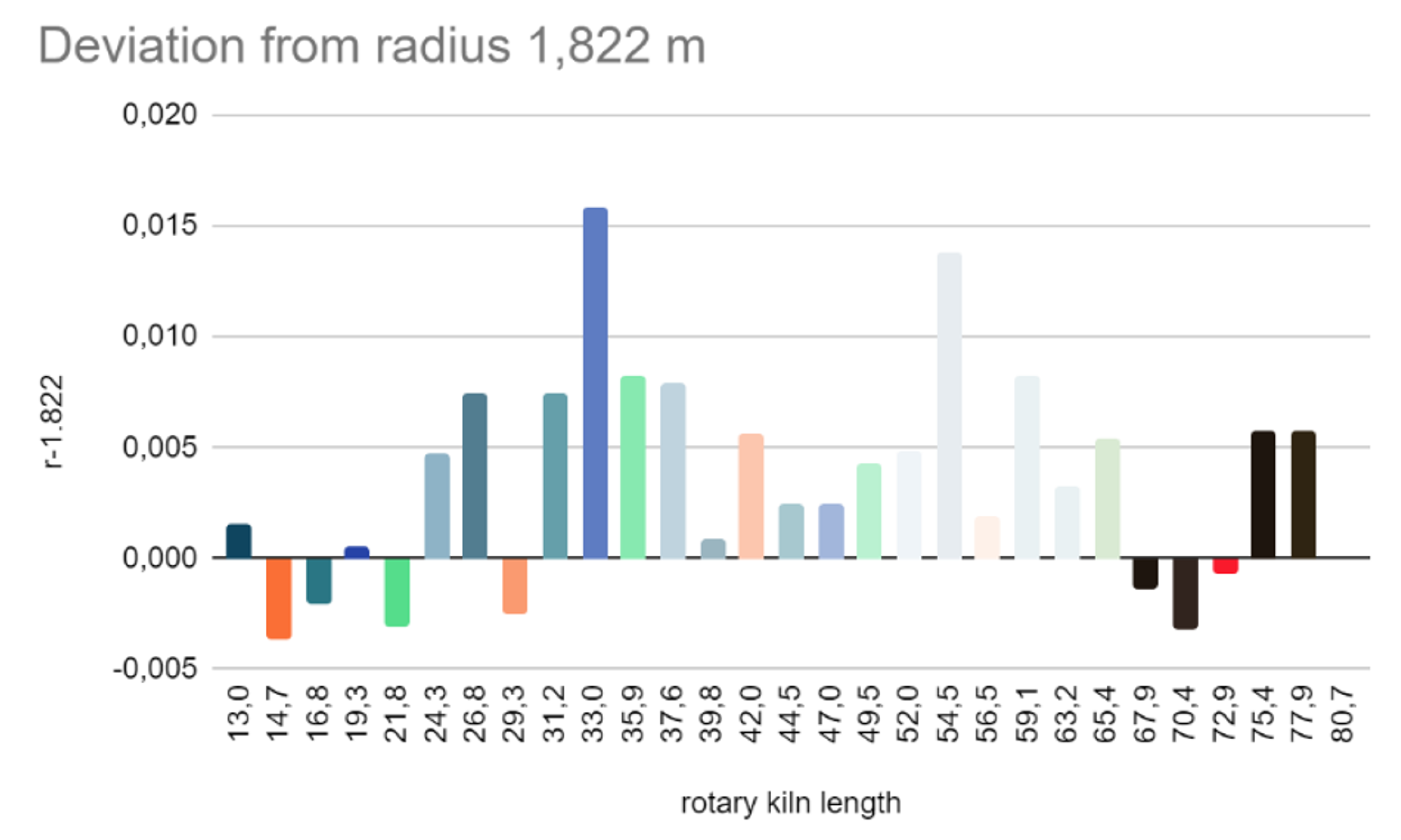
Figure 13.
Steel strips centricity [m]
Disclaimer/Publisher’s Note: The statements, opinions and data contained in all publications are solely those of the individual author(s) and contributor(s) and not of MDPI and/or the editor(s). MDPI and/or the editor(s) disclaim responsibility for any injury to people or property resulting from any ideas, methods, instructions or products referred to in the content. |
© 2023 by the authors. Licensee MDPI, Basel, Switzerland. This article is an open access article distributed under the terms and conditions of the Creative Commons Attribution (CC BY) license (http://creativecommons.org/licenses/by/4.0/).
Copyright: This open access article is published under a Creative Commons CC BY 4.0 license, which permit the free download, distribution, and reuse, provided that the author and preprint are cited in any reuse.


