Submitted:
14 September 2023
Posted:
15 September 2023
You are already at the latest version
Abstract
Keywords:
1. Introduction
2. Methods
2.1. Theoretical formulation (single-neck, multi-neck)
2.1.1. Single-Neck
2.1.2. Multi-Neck
2.2. FEM formulation
2.3. 3D Model and setup
3. Results
3.1 Multi-neck Helmholtz resonators with same number of necks
4. Discussion
4.1 Analytical and FEM approach differencies
5. Conclusions
Author Contributions
Funding
Data Availability Statement
Conflicts of Interest
References
- ISO: Geneva, S. ISO 3382-1: 2009. Measurement of Room Acoustic Parameters - Part 1: Performance spaces. 2009.
- Long, M. Architectural acoustics. 2005, 208.
- Cao, L.; Fu, Q.; Si, Y.; Ding, B.; Yu, J. Porous materials for sound absorption. Composites Communications 2018, 10, 25-35. [CrossRef]
- Kalauni, K.; Pawar, S. A review on the taxonomy, factors associated with sound absorption and theoretical modeling of porous sound absorbing materials. Journal of Porous Materials 2019, 26, 1795-1819. [CrossRef]
- Carbajo, J.; Ramis, J.; Godinho, L.; Amado-Mendes, P. Perforated panel absorbers with micro-perforated partitions. Applied Acoustics 2019, 149, 108-113. [CrossRef]
- Rossing, T.D.; Rossing, T.D. Springer handbook of acoustics; Springer: 2014.
- Komkin, A.; Mironov, M.; Bykov, A. Sound absorption by a Helmholtz resonator. Acoustical Physics 2017, 63, 385-392. [CrossRef]
- Padhye, R.; Nayak, R. Acoustic textiles; Springer: 2016.
- Kanev, N. Resonant Vessels in Russian Churches and Their Study in a Concert Hall. In Proceedings of the Acoustics, 2020; pp. 399-415. [CrossRef]
- Mijic, M.; Sumarac-Pavlovic, D. Analysis of contribution of acoustic resonators found in Serbian Orthodox churches. Building Acoustics 2004, 11, 197-212. [CrossRef]
- Desarnaulds, V.; Loerincik, Y.; Carvalho, A.P. Efficiency of 13th-century acoustic ceramic pots in two Swiss churches. In Proceedings of the Proceedings of the 2001 National Conference on Noise Control Engineering, 2001.
- Pöhlmann, E. Vitruvius De Architectura V: Resounding Vessels in the Greek and Roman Theatre and Their Possible Afterlife in Eastern and Western Churches. Greek and Roman Musical Studies 2021, 9, 157-174. [CrossRef]
- Gilford, C. Helmholtz resonators in the acoustic treatment of broadcasting studios. British Journal of Applied Physics 1952, 3, 86. [CrossRef]
- Namvar Arefi, H.; Ghiasi, S.M.A.; Ghaffari, S.M.; Ramezanghorbani, F.; Sharifpour, S.; Irajizad, P.; Ghoreishi Langroudi, S.D.; Amjadi, A. Conference room reverberation time correction using helmholtz resonators lined with absorbers. Shock and Vibration 2014, 2014. [CrossRef]
- Klaus, J.; Bork, I.; Graf, M.; Ostermeyer, G.-P. On the adjustment of Helmholtz resonators. Applied acoustics 2014, 77, 37-41. [CrossRef]
- Asakura, T. Numerical investigation of the sound-insulation effect of a suspended ceiling structure with arrayed Helmholtz resonators by the finite-difference time-domain method. Applied Acoustics 2021, 172, 107601. [CrossRef]
- Kanev, N. Maximum sound absorption by a Helmholtz resonator in a room at low frequencies. Acoustical Physics 2018, 64, 774-777. [CrossRef]
- Herrero-Durá, I.; Cebrecos, A.; Picó, R.; Romero-García, V.; García-Raffi, L.M.; Sánchez-Morcillo, V.J. Sound absorption and diffusion by 2D arrays of Helmholtz resonators. Applied Sciences 2020, 10, 1690. [CrossRef]
- Huang, S.; Fang, X.; Wang, X.; Assouar, B.; Cheng, Q.; Li, Y. Acoustic perfect absorbers via Helmholtz resonators with embedded apertures. The Journal of the Acoustical Society of America 2019, 145, 254-262. [CrossRef]
- Mahesh, K.; Kumar Ranjith, S.; Mini, R. Inverse design of a Helmholtz resonator based low-frequency acoustic absorber using deep neural network. Journal of Applied Physics 2021, 129. [CrossRef]
- Vergara, E.; Almeida, G.; Barbosa, L.; Lenzi, A.; Carvalho de Sousa, A. Broadband and low-frequency sound absorption of modified Helmholtz resonator combined with porous layer addition. Journal of Applied Physics 2022, 132. [CrossRef]
- Papadakis, N.M.; Stavroulakis, G.E. Review of Acoustic Sources Alternatives to a Dodecahedron Speaker. Applied Sciences 2019, 9, 3705. [CrossRef]
- Papadakis, N.M.; Stavroulakis, G.E. Handclap for Acoustic Measurements: Optimal Application and Limitations. Acoustics 2020, 2, 224-245. [CrossRef]
- Papadakis, N.M.; Antoniadou, S.; Stavroulakis, G.E. Effects of Varying Levels of Background Noise on Room Acoustic Parameters, Measured with ESS and MLS Methods. Acoustics 2023, 5, 563-574. [CrossRef]
- Nia, H.T.; Jain, A.D.; Liu, Y.; Alam, M.-R.; Barnas, R.; Makris, N.C. The evolution of air resonance power efficiency in the violin and its ancestors. Proceedings of the Royal Society A: Mathematical, Physical and Engineering Sciences 2015, 471, 20140905. [CrossRef]
- Papadakis, N.M.; Stavroulakis, G.E. FEM Investigation of the Air Resonance in a Cretan Lyra VIbration 2023.
- Garcia-Alcaide, V.; Palleja-Cabre, S.; Castilla, R.; Gamez-Montero, P.J.; Romeu, J.; Pamies, T.; Amate, J.; Milán, N. Numerical study of the aerodynamics of sound sources in a bass-reflex port. Engineering Applications of Computational Fluid Mechanics 2017, 11, 210-224. [CrossRef]
- Yuan, M.; Cao, Z.; Luo, J.; Chou, X. Recent developments of acoustic energy harvesting: A review. Micromachines 2019, 10, 48. [CrossRef]
- Kone, C.T.; Ghinet, S.; Panneton, R.; Dupont, T.; Grewal, A. Multi-tonal low frequency noise control for aircraft cabin using Helmholtz resonator with complex cavity designs for aircraft cabin noise improvement. INTERNOISE-2021 2021.
- Wang, J.; Rubini, P.; Qin, Q.; Houston, B. A model to predict acoustic resonant frequencies of distributed Helmholtz resonators on gas turbine engines. Applied Sciences 2019, 9, 1419. [CrossRef]
- Fang, N.; Xi, D.; Xu, J.; Ambati, M.; Srituravanich, W.; Sun, C.; Zhang, X. Ultrasonic metamaterials with negative modulus. Nature materials 2006, 5, 452-456. [CrossRef]
- Cai, C.; Mak, C.-M.; Shi, X. An extended neck versus a spiral neck of the Helmholtz resonator. Applied Acoustics 2017, 115, 74-80. [CrossRef]
- Shi, X.; Mak, C.M. Helmholtz resonator with a spiral neck. Applied Acoustics 2015, 99, 68-71. [CrossRef]
- Tang, S.K. On Helmholtz resonators with tapered necks. Journal of sound and vibration 2005, 279, 1085-1096. [CrossRef]
- Ramos, D.; Godinho, L.; Amado-Mendes, P.; Mareze, P. Experimental and numerical modelling of Helmholtz Resonator with angled neck aperture. In Proceedings of the INTER-NOISE and NOISE-CON Congress and Conference Proceedings, 2020; pp. 37-47.
- Duan, M.; Yu, C.; He, W.; Xin, F.; Lu, T.J. Perfect sound absorption of Helmholtz resonators with embedded channels in petal shape. Journal of Applied Physics 2021, 130. [CrossRef]
- Chanaud, R. Effects of geometry on the resonance frequency of Helmholtz resonators. Journal of Sound and Vibration 1994, 178, 337-348. [CrossRef]
- Chanaud, R. Effects of geometry on the resonance frequency of Helmholtz resonators, part II. Journal of sound and vibration 1997, 204, 829-834. [CrossRef]
- Langfeldt, F.; Hoppen, H.; Gleine, W. Resonance frequencies and sound absorption of Helmholtz resonators with multiple necks. Applied Acoustics 2019, 145, 314-319. [CrossRef]
- Selamet, A.; Kim, H.; Huff, N.T. Leakage effect in Helmholtz resonators. The Journal of the Acoustical Society of America 2009, 126, 1142-1150. [CrossRef]
- Lee, I.; Jeon, K.; Park, J. The effect of leakage on the acoustic performance of reactive silencers. Applied acoustics 2013, 74, 479-484. [CrossRef]
- Papadakis, N.M.; Stavroulakis, G.E. FEM Investigation of a Multi-Neck Helmholtz Resonator. Applied Sciences 2023.
- Li, M.; Wu, J.H.; Yuan, X.Y. Metasurface zero-impedance matching mechanism for aerodynamic noise reduction. Journal of Sound and Vibration 2022, 536, 117147. [CrossRef]
- Zolfagharian, A.; Noshadi, A.; Khosravani, M.R.; Zain, M.Z.M. Unwanted noise and vibration control using finite element analysis and artificial intelligence. Applied Mathematical Modelling 2014, 38, 2435-2453. [CrossRef]
- Sakuma, T.; Sakamoto, S.; Otsuru, T. Computational simulation in architectural and environmental acoustics; Springer: 2014.
- Papadakis, N.M.; Stavroulakis, G.E. Finite Element Method for the Estimation of Insertion Loss of Noise Barriers: Comparison with Various Formulae (2D). Urban Science 2020, 4, 77. [CrossRef]
- Papadakis, N.M.; Stavroulakis, G.E. Time domain finite element method for the calculation of impulse response of enclosed spaces. Room acoustics application. Mechanics of Hearing: Protein to Perception: 12th International Workshop on the Mechanics of Hearing 2015, 1703, 100002. [CrossRef]
- Blackstock, D.T. Fundamentals of physical acoustics. 2001.
- Ingard, U. Notes on acoustics; Laxmi Publications, Ltd.: 2010.
- Kuttruff, H. Room acoustics. 2016. [CrossRef]
- Crocker, M.J.; Arenas, J.P. Engineering acoustics: noise and vibration control; John Wiley & Sons: 2021.
- Beranek, L.L.; Mellow, T. Acoustics: sound fields and transducers; Academic Press: 2012.
- Marburg, S.; Nolte, B. Computational acoustics of noise propagation in fluids: finite and boundary element methods; Springer: 2008; Volume 578.
- Ihlenburg, F. Finite element analysis of acoustic scattering; Springer Science & Business Media: 2006; Volume 132.
- Jena, D.; Dandsena, J.; Jayakumari, V. Demonstration of effective acoustic properties of different configurations of Helmholtz resonators. Applied Acoustics 2019, 155, 371-382. [CrossRef]
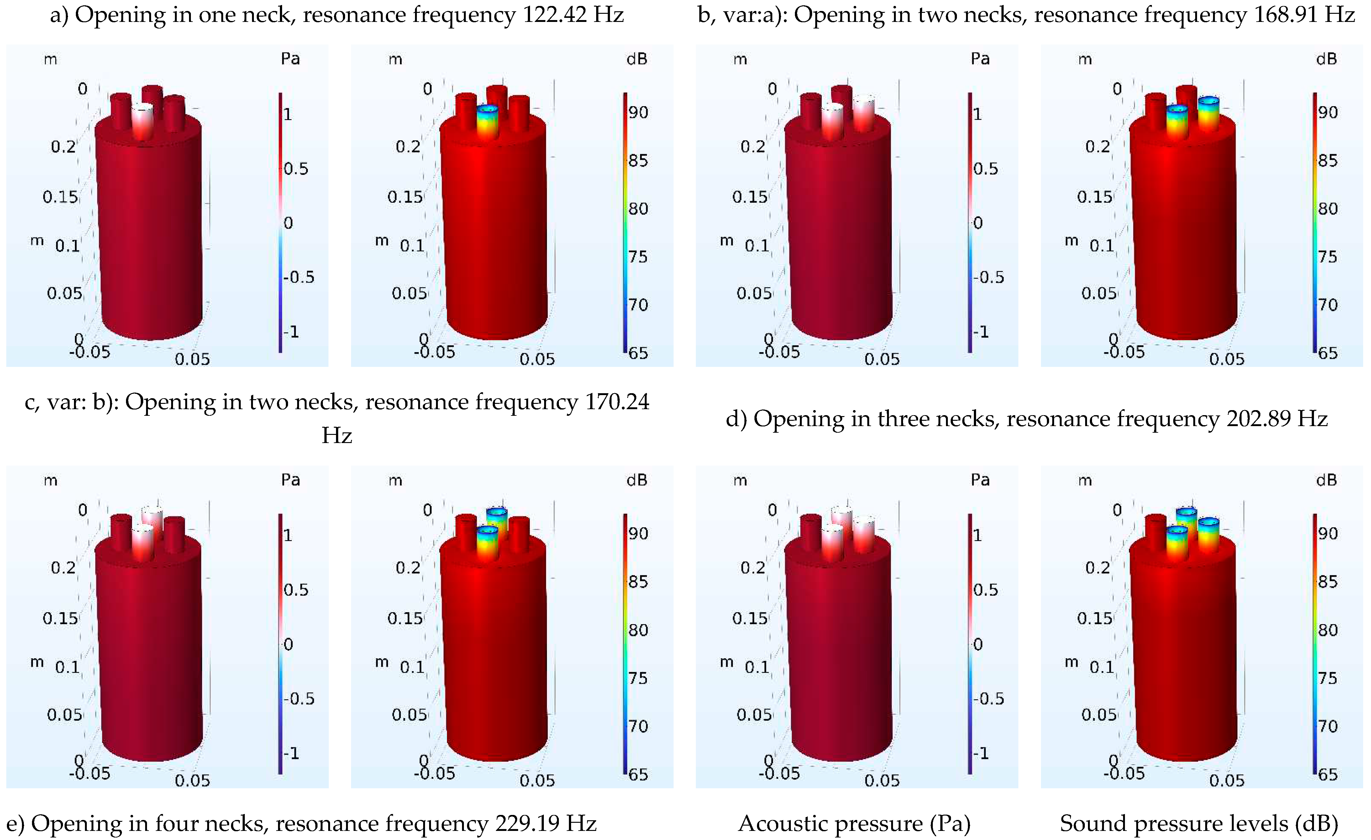
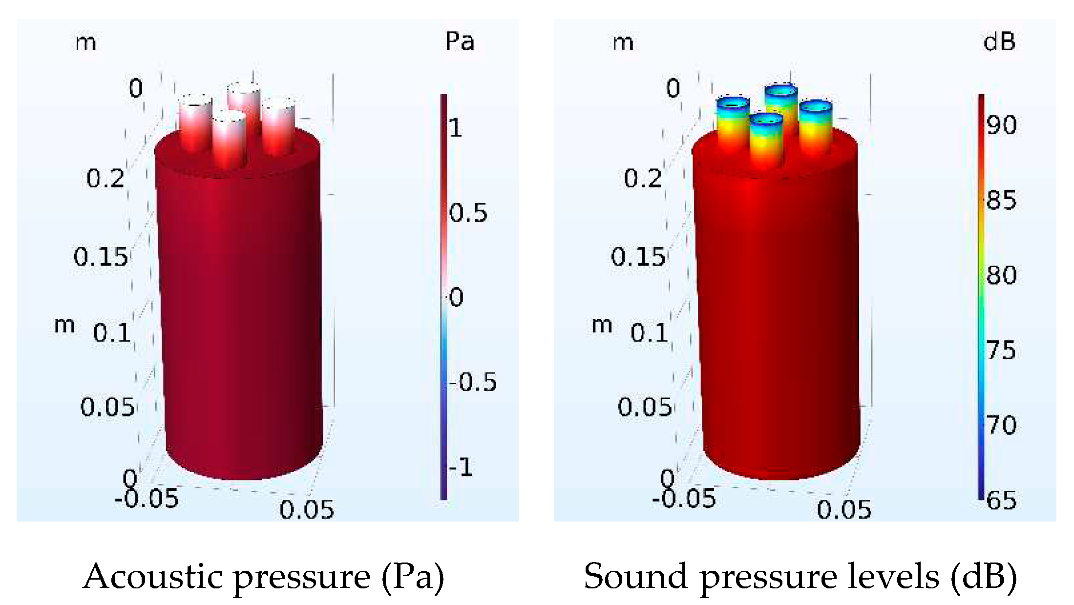


| Number of Necks | Resonant frequency Analytical (Hz) | Resonant frequency FEM (Hz) | Error of calculation (%) Analytical-FEM |
|---|---|---|---|
| 1 | 124.37 | 122.42 | 1.56 |
| 2 (var. a) | 176.15 | 168.91 | 4.11 |
| 2 (var. b) | 176.15 | 170.24 | 3.35 |
| 3 | 216.06 | 202.89 | 6.10 |
| 4 | 249.85 | 229.19 | 7.91 |
| Number of Necks | Resonant frequency Analytical (Hz) | Resonant frequency FEM (Hz) | Error of calculation (%) Analytical-FEM |
|---|---|---|---|
| 1 | 112.91 | 111.06 | 1.16 |
| 2 | 159.77 | 152.14 | 4.78 |
| 3 | 195.79 | 181.87 | 7.11 |
| 4 | 226.20 | 206.03 | 8.92 |
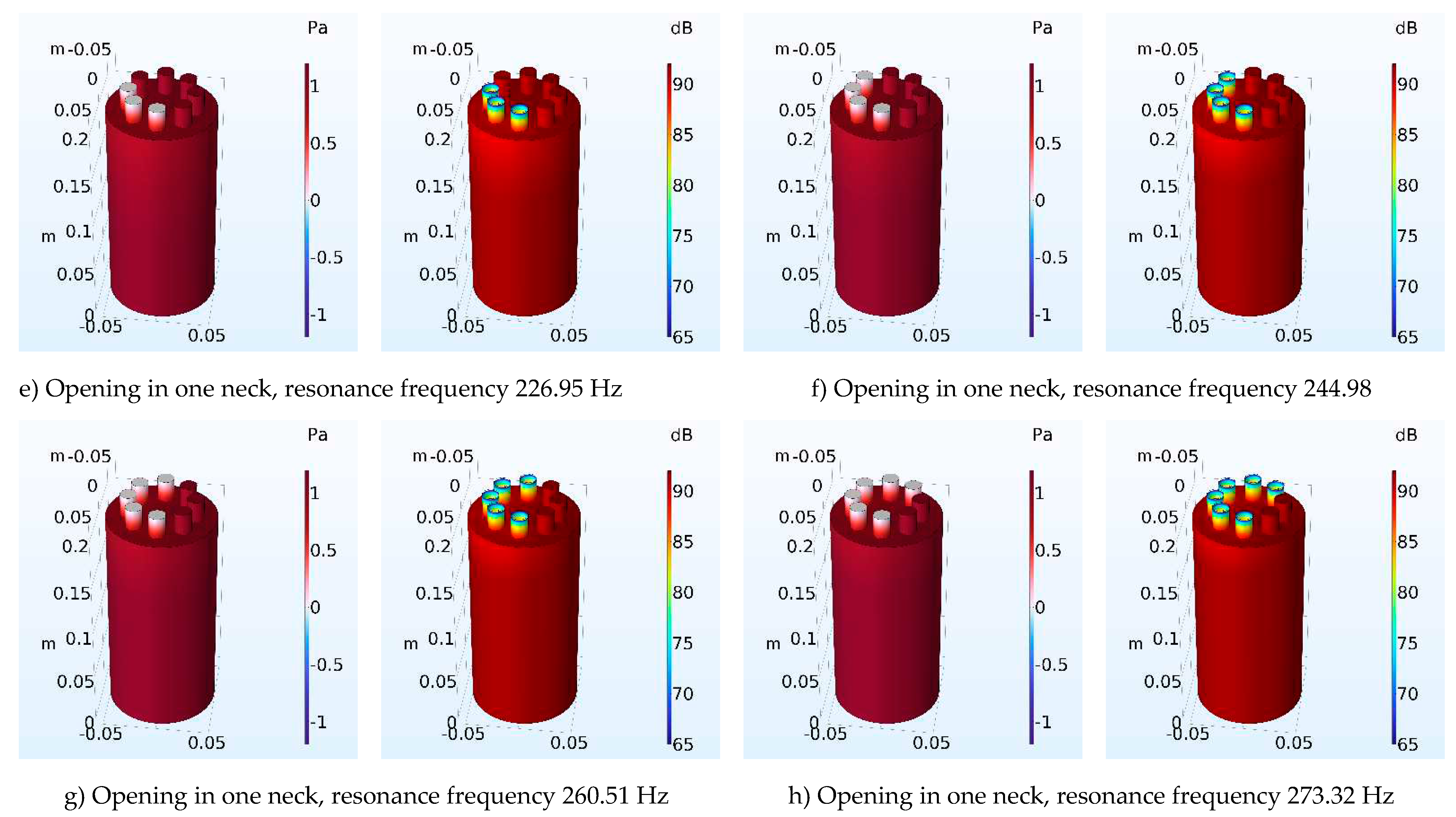
| 5 | 253.04 | 226.95 | 10.31 |
| 6 | 277.35 | 244.98 | 11.67 |
| 7 | 299.73 | 260.51 | 13.09 |
| 8 | 320.61 | 273.32 | 14.78 |
| Number of Necks | Resonant frequency Analytical (Hz) | Resonant frequency FEM (Hz) | Error of calculation (%) Analytical-FEM |
|---|---|---|---|
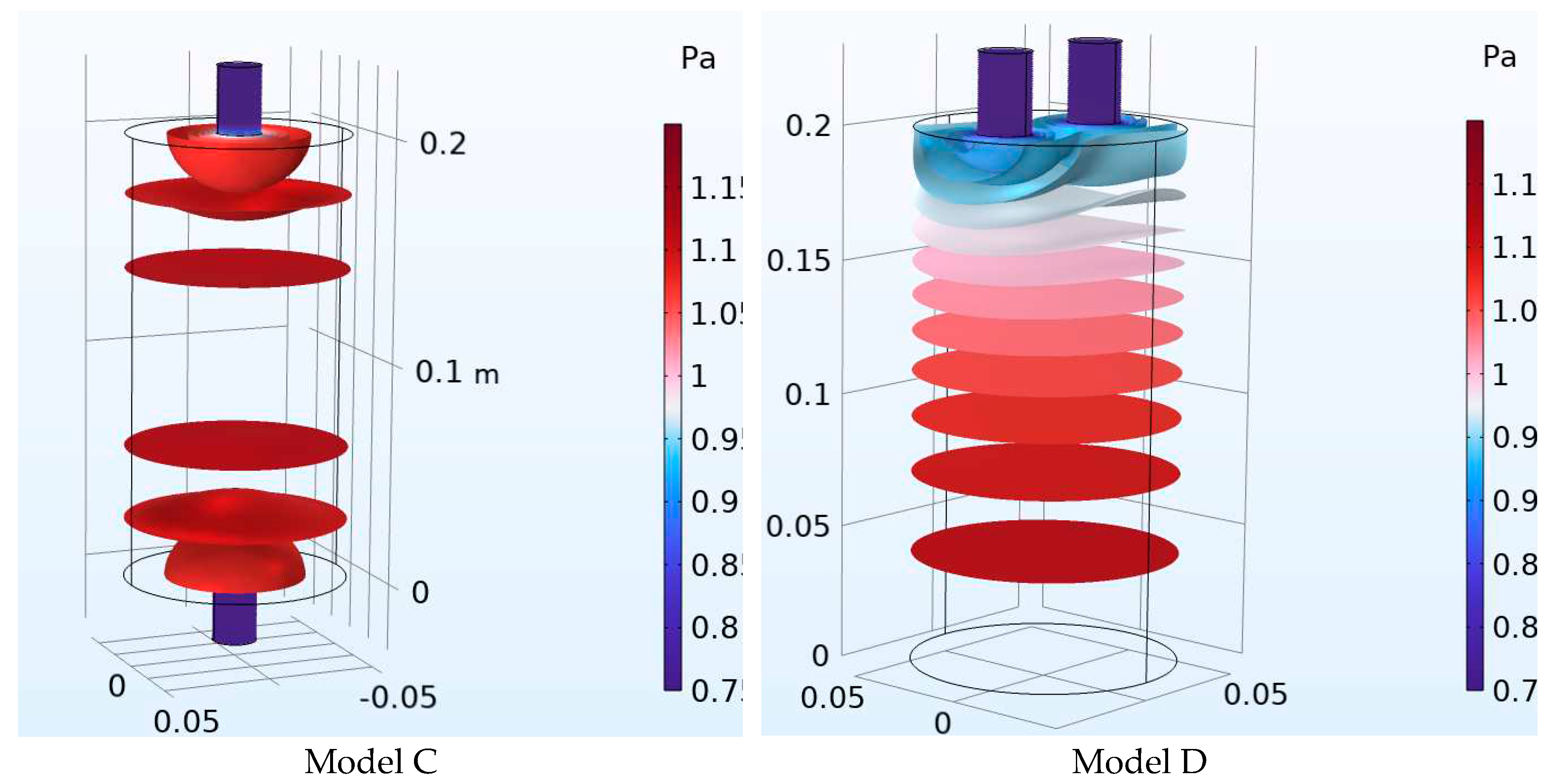
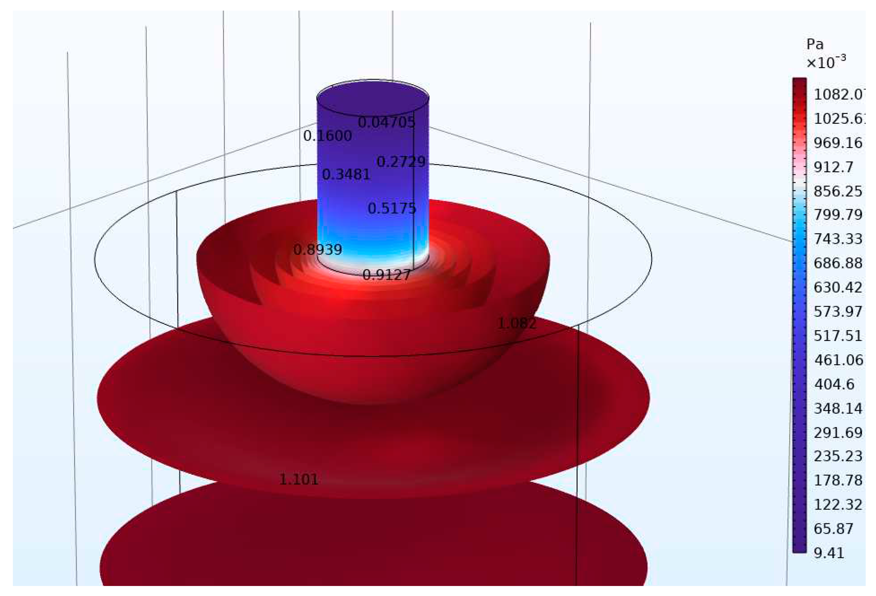
| 1 | 125.11 | 123.86 | 0.99 |
| 1 | 125.11 | 123.86 | 0.99 |
| 2 | 176.73 | 178.78 | 1.19 |
| Number of Necks | Resonant frequency Analytical (Hz) | Resonant frequency FEM (Hz) | Error of calculation (%) Analytical-FEM |
|---|---|---|---|
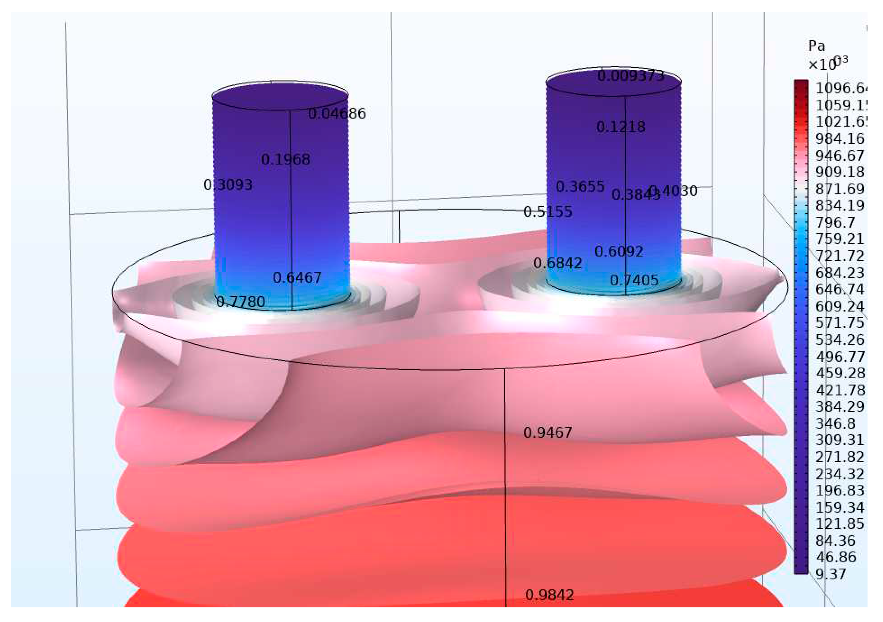
| 1 | 125.11 | 123.11 | 0.99 |
| 1 | 125.11 | 123.11 | 0.99 |
| 2 | 176.73 | 171.12 | 3.17 |
Disclaimer/Publisher’s Note: The statements, opinions and data contained in all publications are solely those of the individual author(s) and contributor(s) and not of MDPI and/or the editor(s). MDPI and/or the editor(s) disclaim responsibility for any injury to people or property resulting from any ideas, methods, instructions or products referred to in the content. |
© 2023 by the authors. Licensee MDPI, Basel, Switzerland. This article is an open access article distributed under the terms and conditions of the Creative Commons Attribution (CC BY) license (http://creativecommons.org/licenses/by/4.0/).


