1. Introduction
The solid oxide membrane (SOM) process has attracted considerable attention as a new metal reduction technology due to its high cost-effectiveness and low greenhouse gas emissions [
1]. Yttria-stabilized zirconia (YSZ) is the preferred material for SOM due to its high oxygen ion conductivity within the operating temperature range (1000-1300 ℃) [
2]. However, corrosion issues with YSZ in molten fluoride flux have become a limiting factor in the operational lifespan of SOM electrolysis processes.
Studies are underway to enhance molten salt corrosion resistance caused by molten fluoride flux, as it is crucial for the solid oxide membrane (SOM) process. Various methods have been investigated to prevent yttrium leaching in molten electrolytes, including the addition of additives such as YF
3, Y
2O
3 and MgO. However, these are not suitable alternatives because they can inevitably influence the electrolyte [
3,
4,
5,
6]. Research has been conducted to investigate new compositions or additives to address the issue of yttrium leaching. Calcia-stabilized zirconia (CSZ) exhibits lower ionic conductivity and corrosion resistance compared to YSZ, while magnesia-stabilized zirconia (MSZ) demonstrates superior corrosion resistance to YSZ but has a higher tendency for spontaneous destabilization at operating temperatures (1000-1300 ℃) and lower ionic conductivity [
7,
8,
9,
10]. As a result, research has been conducted to improve the corrosion resistance by doping more acidic stabilizing elements (such as CeO
2, In
2O
3, Sc
2O
3, etc.) into YSZ. It has been observed that CeO
2 codoped yttria-stabilized zirconia exhibits enhanced corrosion resistance [
11,
12]. However, an increase in the amount of CeO
2 doping has been found to lead to a decrease in the cubic phase and ionic conductivity, along with the drawback of poor sinterability [
13].”
Zirconia is stabilized into high-temperature tetragonal and cubic phases by adding lower-valency cations. The doped ions create oxygen vacancies to maintain electrical neutrality. Ion conduction in zirconia occurs through thermally activated hopping, involving the long-range transport of oxygen ions to the nearest oxygen vacancies [
14]. The location of the oxygen vacancy is very important because the oxygen ion conductivity in zirconia is highly dependent on the structure around the oxygen vacancies [
15]. While simple electrostatic arguments suggest that oxygen vacancies are positioned near the doped cations, the actual placement is known to vary depending on the valence state and ion size of the dopants. Therefore, utilizing X-ray absorption fine structure spectroscopy (XAFS) to analyze the local atomic structure around specific atoms is an effective approach [
16,
17,
18]. Among dopants, ZnO is expected to not only enhance phase stability but also serve as a sintering aid. However, there has been no research on the formation and ordering behavior of oxygen vacancies due to ZnO doping.
We studied the formation and ordering of oxygen vacancies and the destabilization behavior due to corrosion in 4Ce4YSZ with ZnO doping. XRD analysis was performed to confirm the phase transformation resulting from ZnO doping, and interplanar distances were measured through TEM-SAED analysis. The formation and ordering behavior of oxygen vacancies were analyzed using extended X-ray absorption fine structure (EXAFS), and the conductivity was investigated through impedance spectroscopy. A molten salt test was conducted to confirm the corrosion resistance of ZnO-doped 4Ce4YSZ, and the resulting destabilization behavior was analyzed.
2. Experiment
Using the sol-gel method, 4Ce4YSZ powders were synthesized using sol-gel method. ZrCl4 (ATI, ≥ 99.9%), Y(NO3)3·6H2O (Sigma-Aldrich, ≥ 99.8%) and Ce(NO3)3·6H2O (Alfa Aesar, ≥ 99.9%) precursors were dissolved in deionized water according to the stoichiometry of the composition to prepare a homogeneous mixed metal solution. Then, the cation solutions, citric acid (CA) and ethylene glycol (EG) were mixed in a beaker, which was called a sol state, in sequence at a total metal ion:citric acid:ethylene glycol mole ratio of 1:4:16. The sol was heated with stirring at 80 ℃, and the pH was adjusted to approximately 10 by adding a 1 N NH4OH solution. An opaque viscous gel obtained by continuous stirring and heating was baked to solidify in an oven at 400 ℃ for 4 h. The solidified precursors were then calcinated in air at 1200 ℃ for 2 h. Figure 3 summarizes the entire synthesis procedures in a flow chart. The powder was uniaxially pressed at 3 ton/m2 to produce a 20mm disk specimen and the green body was sintered at 5 ℃/min to various temperature (1200 - 1600 °C) for 2h. ZnO (Sigma-Aldrich, ≥ 99.99%) was introduced into 4Ce4YSZ powders by the mechanical mixing method. The mixed powders were ball milled in ethanol for 24 h and subsequently dried. The dried powders were calcinated in air at 1200 ℃.
The molten salt test was conducted using the eutectic composition of calcium fluoride (98%, Junsei Chemical Co. Ltd.) and sodium fluoride (98%, Junsei Chemical Co. Ltd.) by ball milling at 200 rpm in Nalgene bottles for 12 h. Then, typically, 0.7 g of the mixed powder was pelletized (1 ton/m2) in a cylindrical 15-mm die. The obtained fluoride composite green bodies were then attached to the surfaces of discs and heated at 1000 ℃ for 100 h.
The densities of sintered pellets were determined using the Archimedes’ method by immersing the samples in distilled water. X-ray diffraction (XRD) patterns of the specimens were collected at room temperature using a step scan procedure (2θ = 10-90°, with a step interval of 0.02°) and Cu-Kα radiation on a Rigaku Ultima-IV XRD instrument. Transmission electron microscopy (TEM, JEOL, JEM-2100) was used at the KBSI Busan center to analyze the microstructure of the powders. Extended X-ray absorption fine structure spectroscopy (EXAFS) experiments were conducted at both the Zr K-edge and Y K-edge using the EXAFS facility at the 7D XAFS beamline in the Pohang Accelerator Laboratory (PLS-II, Pohang, Korea). AC impedance measurements were carried out using an Ivium-Stat instrument (Ivium, Netherlands) within a frequency range from 106 Hz to 10-2 Hz, with an excitation voltage of 10 mV, at an operating temperature of 700 °C, under air conditions. The SEM images of the samples were obtained by using a JSM-IT800 scanning electron microscope.
3. Results and discussion
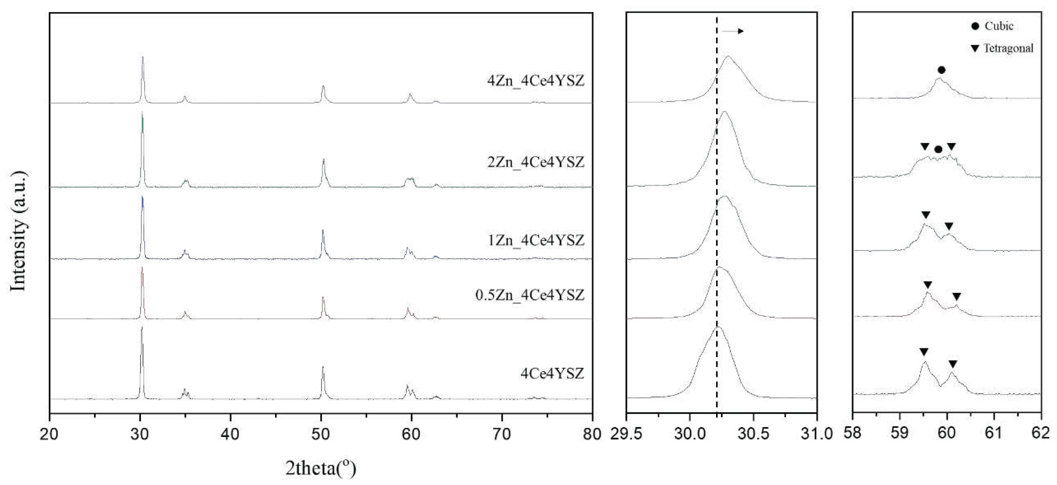
The XRD patterns of the powders calcined in air at 1200 ℃ for 2h were shown in
Figure 1. It confirms the formation of the tetragonal phase (PDF 49-1642) in 4Ce4YSZ. With an increase in the amount of ZnO doping increases, the cubic phase (PDF 50-1089) gradually becomes more prominent, as shown in
Figure 1(c). In 4Zn_Ce4YSZ, the cubic phase was dominant, and no other phases were observed. As shown in
Figure 1(b), with the increasing concentrations of ZnO, the (111) peak shifted to a higher angle. This result suggests that Zn
2+ ions, with a smaller ionic radius (60 Å) than Zr
4+ (84 Å), are incorporated into the solid solution as substitutional elements, stabilizing the cubic phase through the formation of oxygen vacancies [
19].
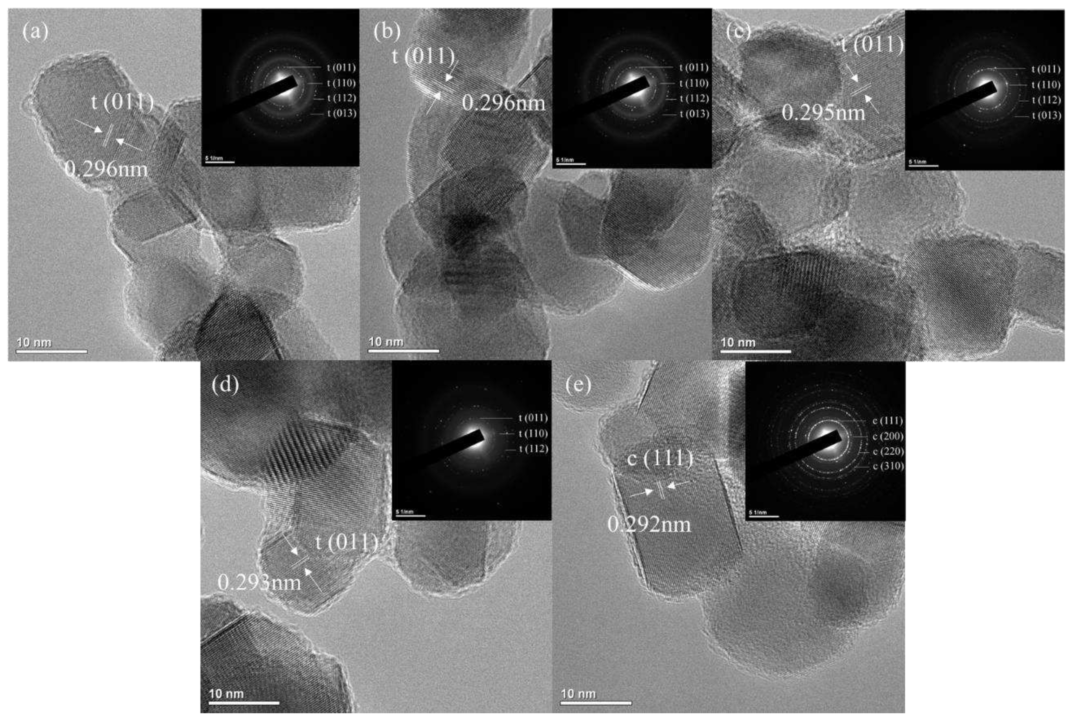
TEM images of Zn-doped 4Ce4YSZ are shown in
Figure 2. The powders synthesized through the sol-gel method had an average size of 20-30 nm, and no significant changes in powder size were observed with increasing Zn doping levels. Tetragonal phases were confirmed in 4Ce4YSZ and 2Zn_4Ce4YSZ, while a cubic phase was observed in 4Zn_4Ce4YSZ. The lattice parameter tended to decrease as Zn doping increased through the d-spacing (0.296 nm, 0.293 nm) of 4Ce4YSZ and 2Zn_4Ce4YSZ, which was consistent with the XRD results.
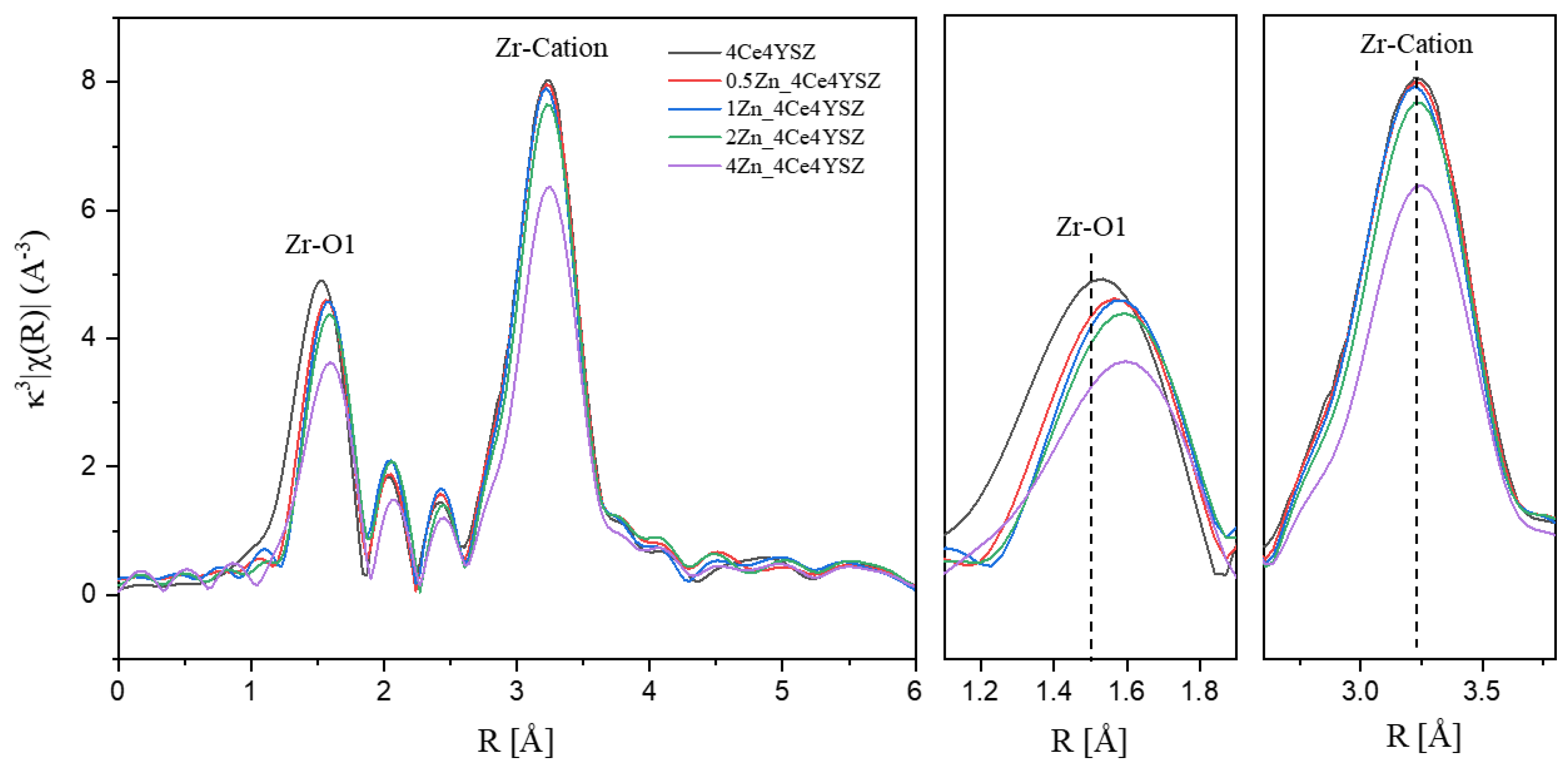
To investigate the formation and ordering behavior of oxygen vacancies due to Zn doping, Zr K-edge Fourier transform extended X-ray absorption fine structure(EXAFS) was conducted on powders calcinated in air at 1200°C for 2 hours. The results are presented in
Figure 3, and EXAFS signals were obtained in the range of 3 < K < 12 Å using a Hanning window. The 1st peak appearing at approximately 1.5 Å is attributed to the Zr-O bonding, while the 2nd peak observed near 3.25 Å is associated with Zr-cation interactions [
20,
21]. The intensity of the Zr-O peak decreased with increasing ZnO doping. This result is attributed to the metallic substitution reaction, which forms oxygen vacancies in zirconia to maintain electron neutrality [
22].
The interatomic distance between Zr and its first nearest neighbors showed an increasing trend with the increasing ZnO doping level. In yttria-stabilized zirconia, the presence of oxygen vacancies near Zr results in a reduction in the Zr-O interatomic distance, causing cubic zirconia to have a smaller Zr-O interatomic distance compared to tetragonal zirconia [
20,
23]. Therefore, it is considered that oxygen vacancies were formed near Zn
2+ (60 Å), which is smaller than Zr
4+ (84 Å) upon ZnO doping. This resulted in a decrease in oxygen vacancies near zirconia, leading to an increase in the Zr–O1 interatomic distance. Additionally, a decrease in the intensity of the Zr-Cation peak was observed, which can be attributed to an increase in structural distortion with increasing dopant concentration [
25].
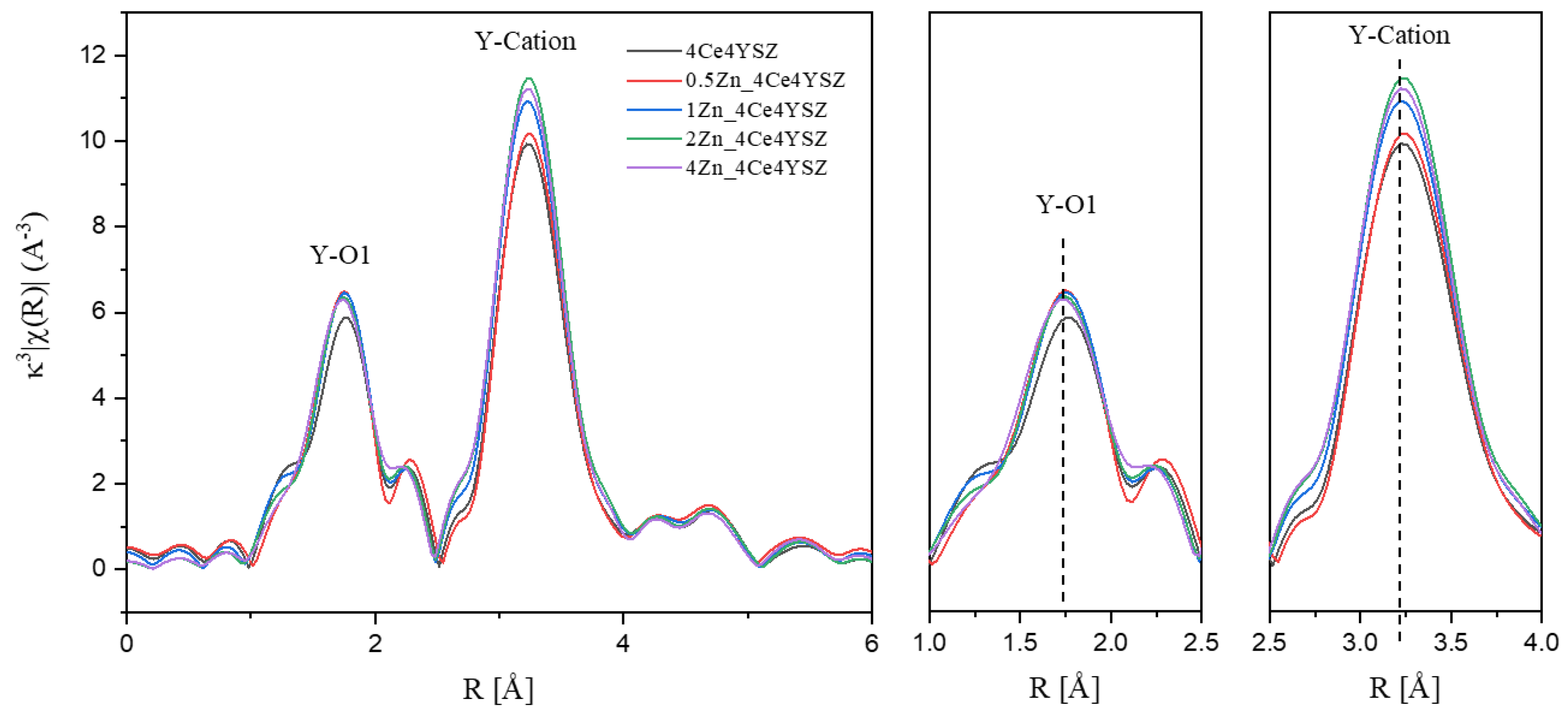
Figure 4 displays the Y K-edge Fourier transform data, with EXAFS signals obtained in the range of 3 < K < 11.5 Å using a Hanning window. The 1st peak, meaning Y-O bonding, appeared at approximately 1.75 Å, and the difference in first cation-oxygen distances between Y-O and Zr-O is attributed to the different sizes of Zr
4+ and Y
3+ ions [
18]. The Y-O interatomic distance showed little variation, and there was almost no change in the intensity of the Y-O1 peak. These results indicate that the oxygen vacancies formed as a result of Zn doping are not located in the Y neighboring oxygen shell. Similar to the Zr-O interatomic distance, the lack of an increase in the Y-O interatomic distance suggests that oxygen vacancies primarily reside near Zr cations, and there are no oxygen vacancies to move to the Zn neighboring oxygen shell.
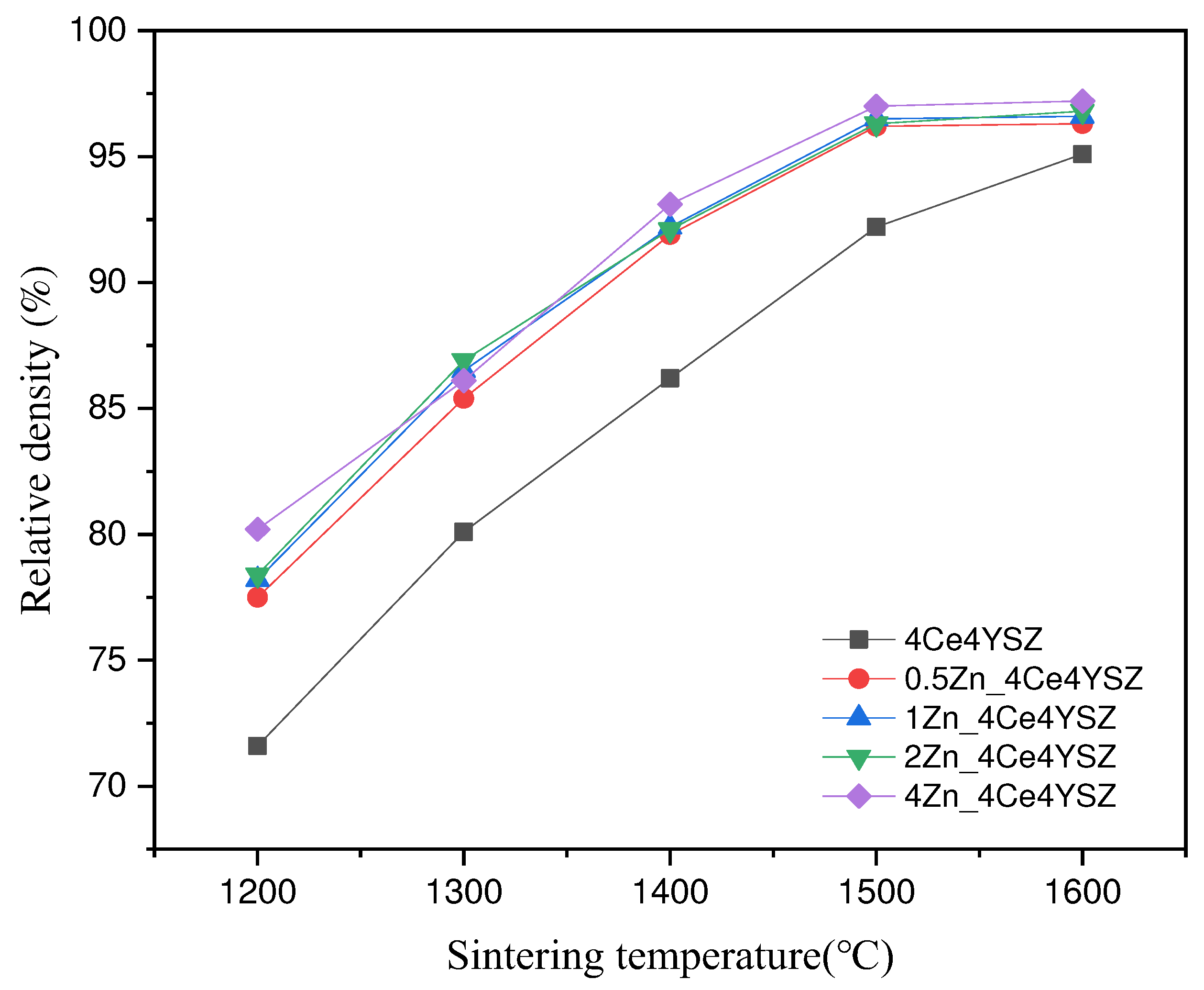
Figure 5 shows the calculated relative densities of the samples sintered at various temperatures with a duration of 2h. As the sintering temperature increased, the relative density consistently increased, and 4Ce4YSZ increased from 71.6% (1200 ℃) to 95.1% (1600 ℃). On the other hand, 4Zn_4Ce4YSZ exhibited a relative density of 80.2% at 1200℃, indicating a higher relative density than in the undoped case, and it reached a 97% relative density at 1500℃. This confirms that Zn can address the sinterability issues associated with CeO
2.
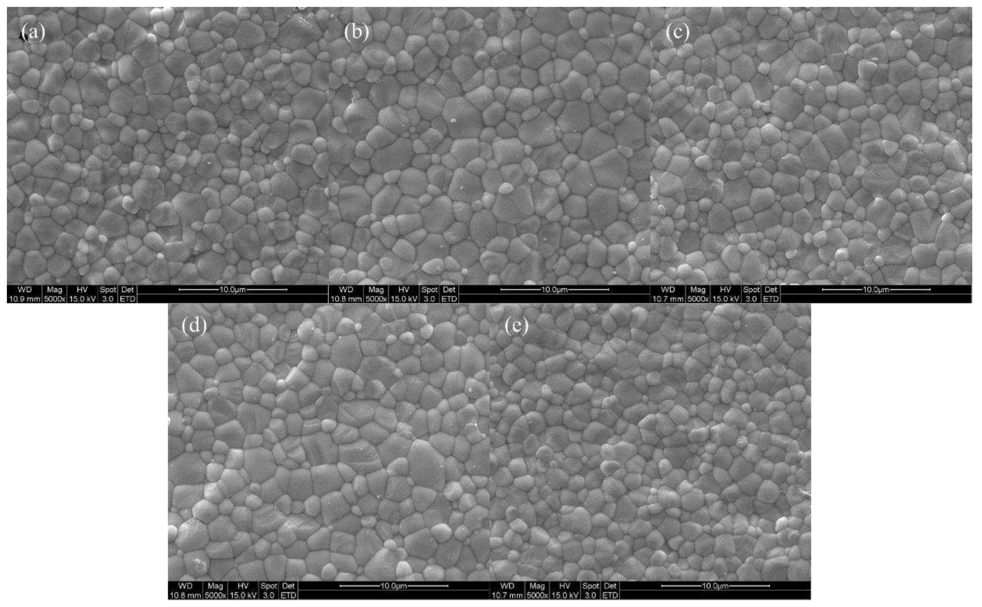
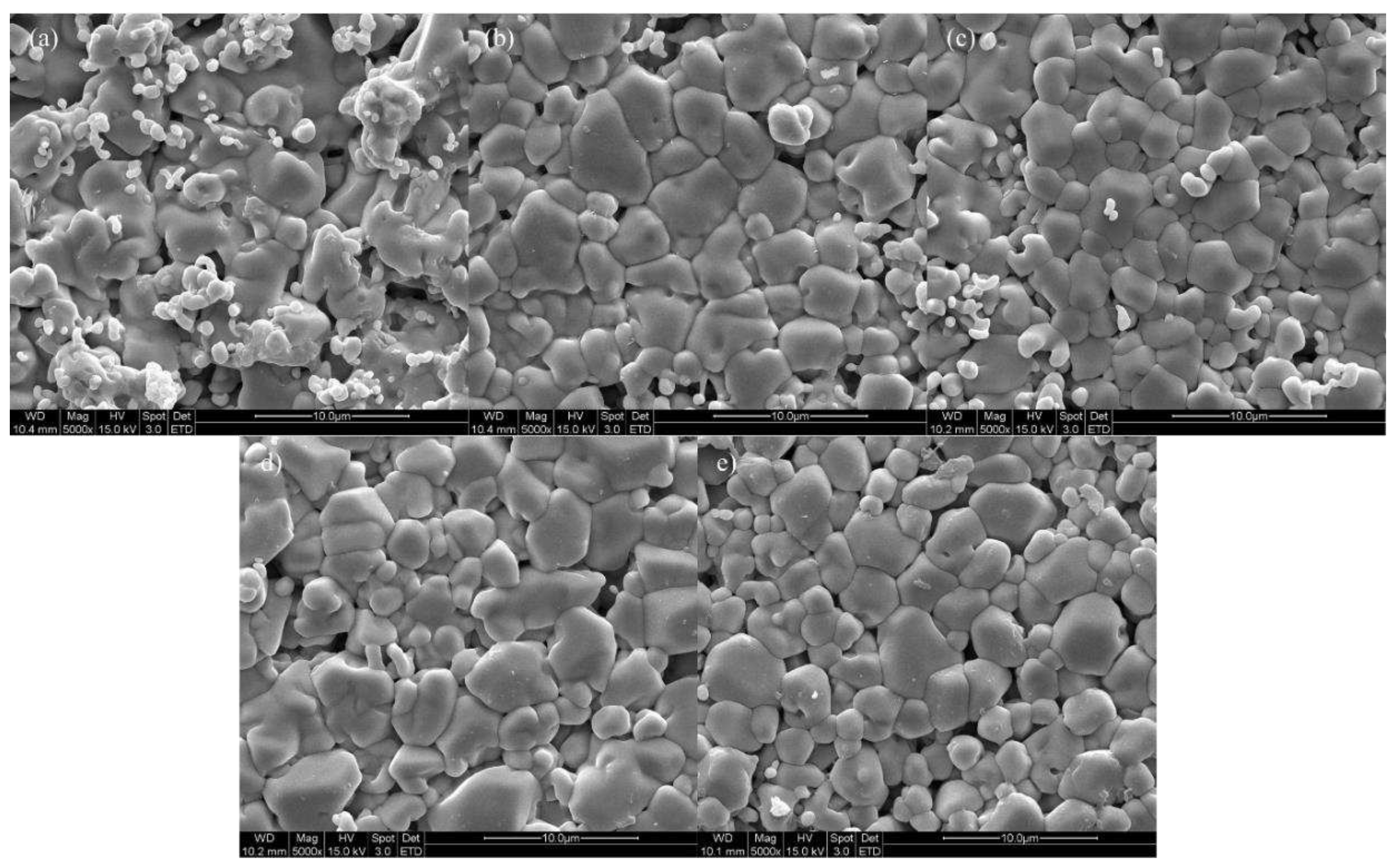
Figure 6 displays SEM images of specimens sintered at 1600 ℃ for 2 hours, confirming that all specimens were well sintered with a dense structure. Grain sizes were measured by analyzing SEM images based on ISO 13383-1, resulting in grain sizes of 2.12, 2.17, 2.21, 2.30, and 2.16 μm, showing an increasing trend in grain size with Zn doping [
26].
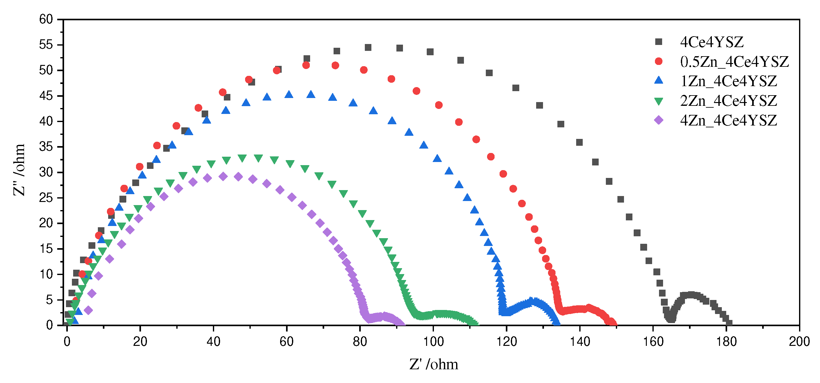
Figure 7 presents the Nyquist plot of impedance data measured at 700 ℃. Two arcs represent the grain interior resistance (R
gi) and the total grain boundary resistance (R
gb), with the total resistance (R
t) being the sum of these two arcs [
27].
In
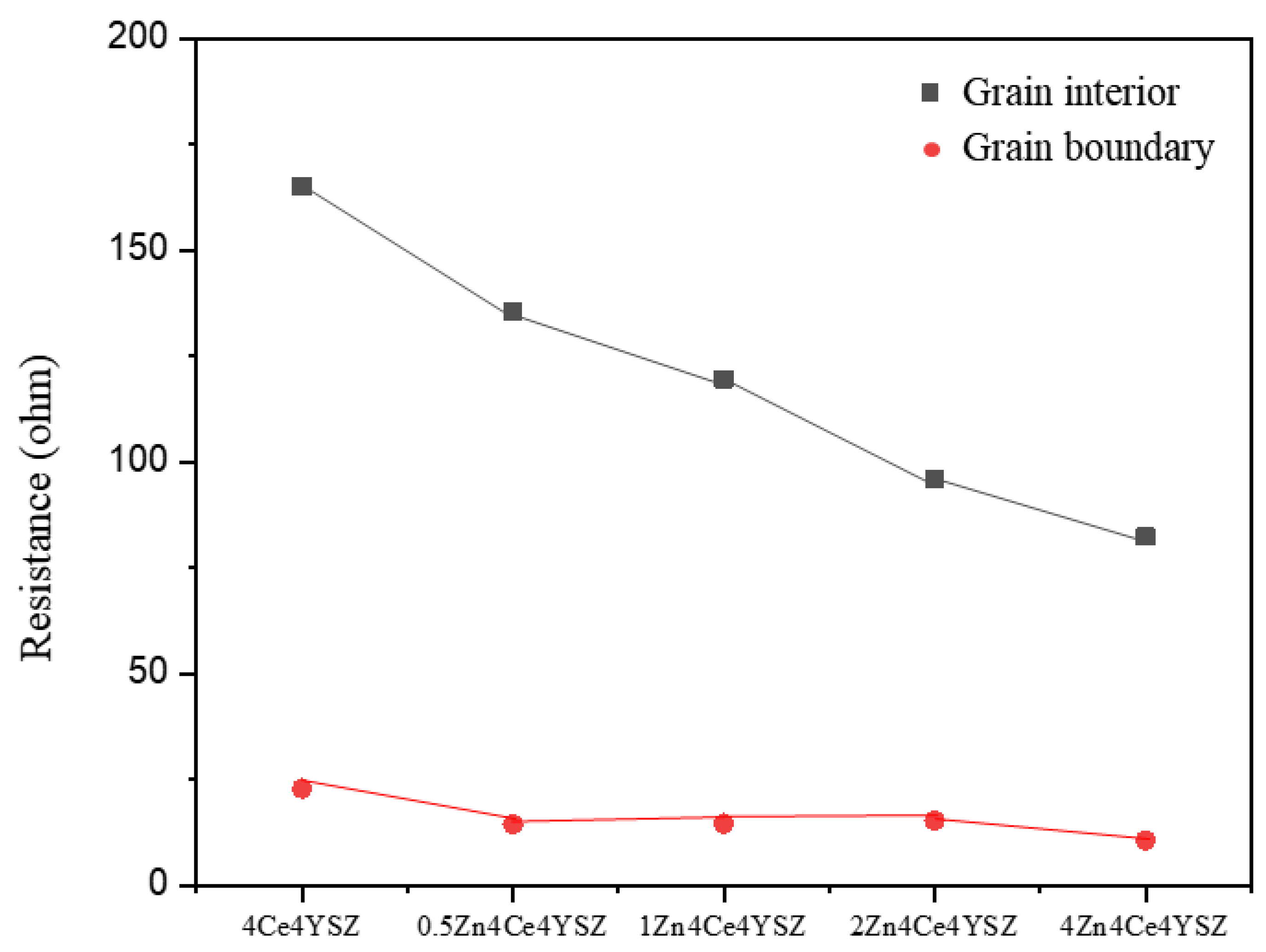
Figure 8, it was observed that R
gi gradually decreased from 165.10 Ω (4Ce4YSZ) to 82.33 Ω (4Zn_4Ce4YSZ) with increasing ZnO doping level. This result indicates that ZnO dissolved in ZrO
2 forms oxygen vacancies, increasing the conductivity [
22]. Similarly, R
gb also gradually decreased from 22.84 Ω (4Ce4YSZ) to 10.60 Ω (4Zn_4Ce4YSZ). As the grain size increased with ZnO doping, the grain boundaries decreased. It is believed that ZnO could change the oxygen-ion conductive channel structure at the grain boundaries, leading to an improvement in R
gb conductivity [
28].
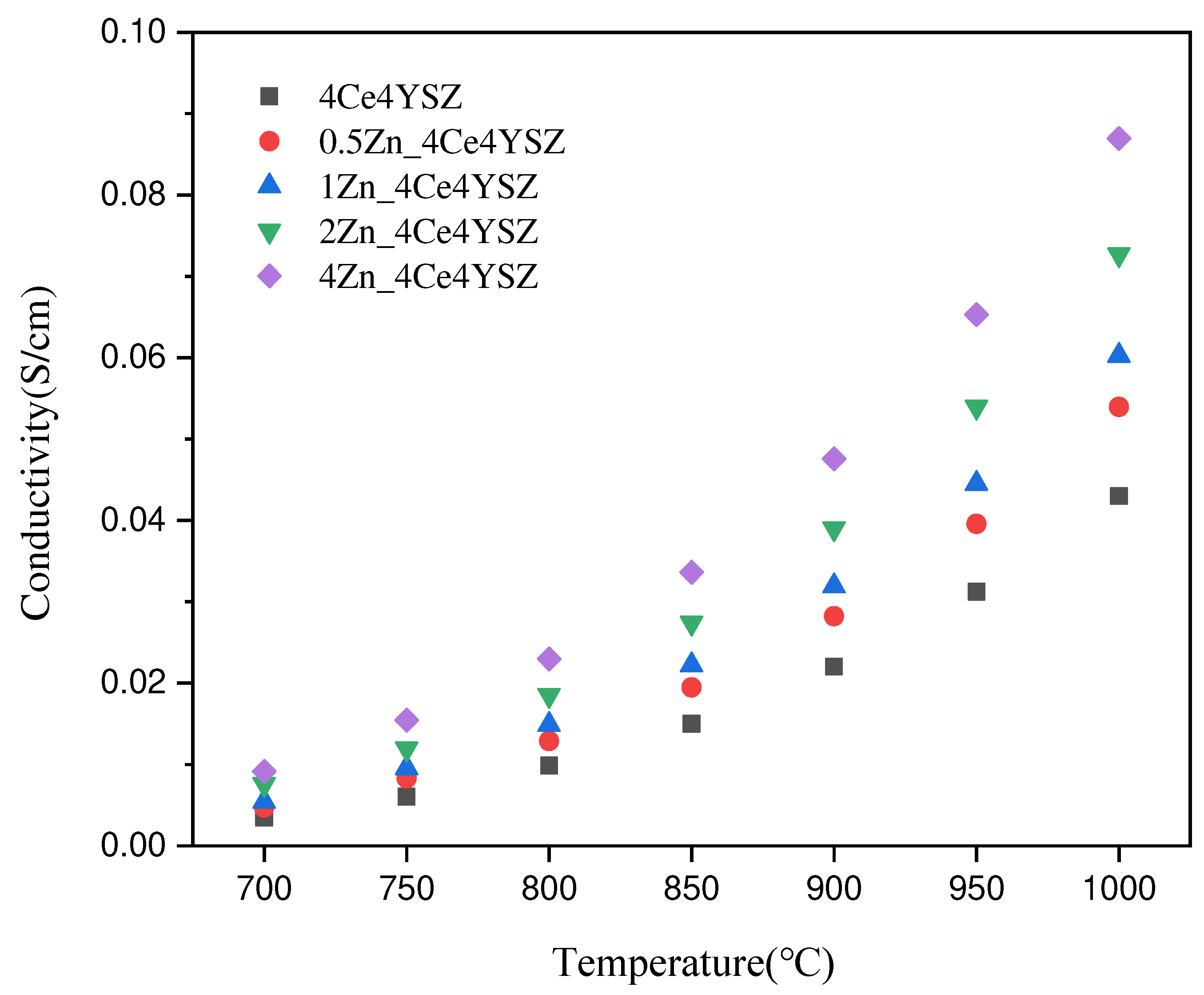
Figure 9 represents the total conductivity calculated based on impedance data and fitted with the Equation (3) below.
Where
represents the thickness of the specimen, while
is the area of the electrode. The conductivity, which was 0.0430 S/cm in 4Ce4YSZ, gradually increased with the increasing ZnO doping level, reaching 0.0870 S/cm in 4Zn_4Ce4YSZ. The increase in oxygen vacancies with increasing ZnO doping and the cubic phase formation contributed to the increase in conductivity [
29].
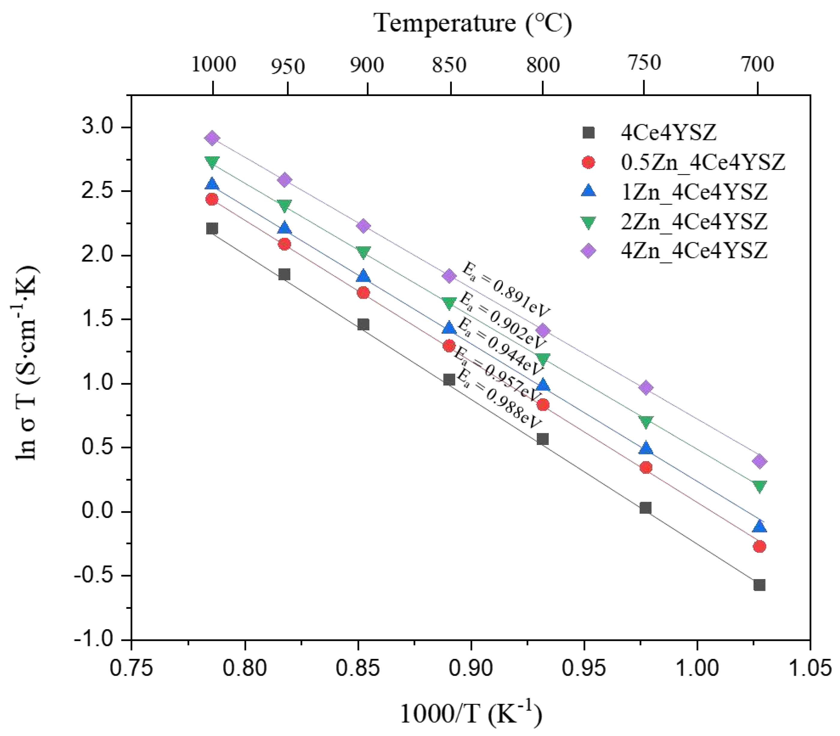
Figure 10 represents the Arrhenius plots of total conductivity, and the dependence of ionic conductivity (
) on temperature (
) was obtained using the Arrhenius equation.
Where represents the Boltzmann constant, and denotes the activation energy. The activation energy () decreased progressively from 0.988 eV (4Ce4YSZ) to 0.891 eV (4Zn_4Ce4YSZ). These results suggest that the oxygen vacancies formed due to ZnO doping do not form defect associations by interacting with positively charged Zn2+.
Figure 11 displays SEM images of the sample surfaces after a 100 hr molten salt test at 1000 ℃ using the eutectic composition of CaF
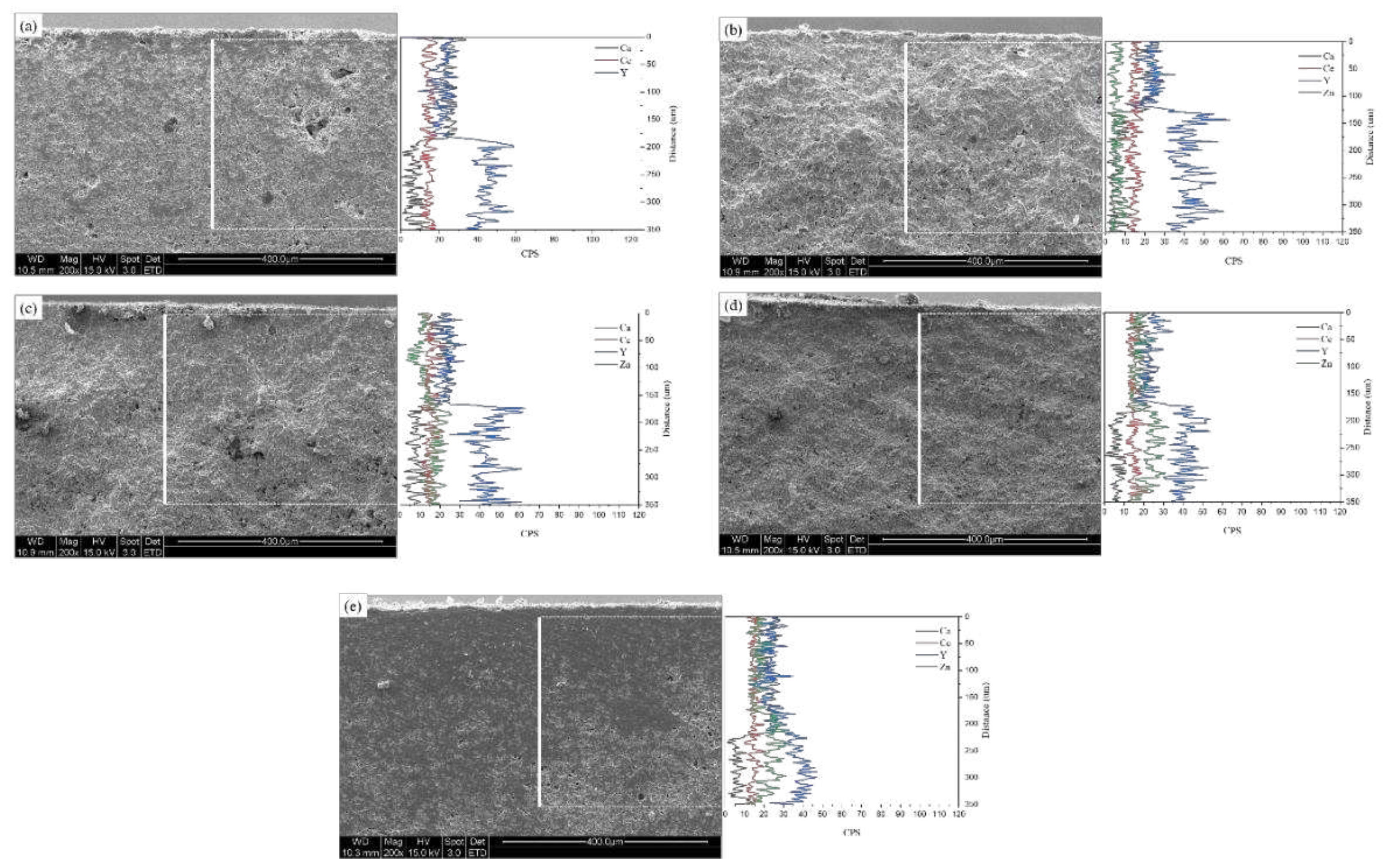
2 and NaF. Some remnants of the molten salt can be observed on the sample surface. In all samples, corrosion occurred due to the molten salt, resulting in the formation of pores, and the grains were larger than those before the corrosion. To confirm the destabilization caused by the molten salt, cross-sections were subjected to EDS line scans, as depicted in
Figure 12. The detection of the Ca element in the EDS line scan indicated the penetration of the molten salt, and the estimation of the depth of molten salt infiltration was possible to estimate through the of decrease in Ca intensity. The molten salt penetration depth decreased from 183.8 μm (4Ce4YSZ) to 128.9 μm (0.5Zn_4Ce4YSZ) and then increased to 218.9 μm (4Zn_4Ce4YSZ). The Y element exhibited low intensity on the surface, which increased almost in correspondence with the depth of salt penetration. This result indicated corrosion by the molten flux and the formation of a yttrium depletion layer (YDL) [
30]. A Zn element intensity decrease was observed in 1, 2, and 4Zn_4Ce4YSZ, suggesting the formation of a depletion layer due to corrosion, but the decrease in Zn intensity was lower than that of yttrium. On the other hand, Ce element loss was minimal, indicating the stability of the acidic stabilizing element, CeO
2, in the SOM electrolysis process [
8].
Figure 13 shows the XRD of the sample surfaces after the molten salt test, and monoclinic phase formation was observed in the 4Zn_4Ce4YSZ sample, indicating destabilization due to corrosion. The higher-angle shift in the (111) peak observed in all samples after corrosion indicates zirconia lattice contraction due to the expulsion of Y
3+ (1.04 Å), which is larger than Zr
4+ (84 Å), from the lattice during corrosion.
Figure 1.
a) XRD diffraction patterns (b) (111) peaks and (c) (311) peaks of ZnO-doped 4Ce4YSZe.
Figure 1.
a) XRD diffraction patterns (b) (111) peaks and (c) (311) peaks of ZnO-doped 4Ce4YSZe.
Figure 2.
(a) TEM images and SAED patterns of (a) 4Ce4YSZ, (b) 0.5Zn_4Ce4YSZ, (c) 1Zn_4Ce4YSZ, (d) 4Zn_4Ce4YSZ.
Figure 2.
(a) TEM images and SAED patterns of (a) 4Ce4YSZ, (b) 0.5Zn_4Ce4YSZ, (c) 1Zn_4Ce4YSZ, (d) 4Zn_4Ce4YSZ.
Figure 3.
Zr K-edge Fourier transform data of ZnO-doped 4Ce4YSZ.
Figure 3.
Zr K-edge Fourier transform data of ZnO-doped 4Ce4YSZ.
Figure 4.
Y K-edge Fourier transform data of ZnO-doped 4Ce4YSZ.
Figure 4.
Y K-edge Fourier transform data of ZnO-doped 4Ce4YSZ.
Figure 5.
Relative density vs. sintering temperature for Zn doped 4Ce4YSZ.
Figure 5.
Relative density vs. sintering temperature for Zn doped 4Ce4YSZ.
Figure 6.
SEM surface images of (a) 4Ce4YSZ, (b) 0.5Zn_4Ce4YSZ, (c) 1Zn_4Ce4YSZ, (d) 2Zn_4Ce4YSZ and (e) 4Zn_4Ce4YSZ sintered at 1600 ℃.
Figure 6.
SEM surface images of (a) 4Ce4YSZ, (b) 0.5Zn_4Ce4YSZ, (c) 1Zn_4Ce4YSZ, (d) 2Zn_4Ce4YSZ and (e) 4Zn_4Ce4YSZ sintered at 1600 ℃.
Figure 7.
Nyquist plot of ZnO-doped 4Ce4YSZ obtained in air at 700℃.
Figure 7.
Nyquist plot of ZnO-doped 4Ce4YSZ obtained in air at 700℃.
Figure 8.
Resistances of grain interior and grain boundary derived from impedance spectroscopy.
Figure 8.
Resistances of grain interior and grain boundary derived from impedance spectroscopy.
Figure 9.
Total conductivity of ZnO-doped 4Ce4YSZ.
Figure 9.
Total conductivity of ZnO-doped 4Ce4YSZ.
Figure 10.
Arrhenius plots of the total conductivity in ZnO-doped 4Ce4YSZ.
Figure 10.
Arrhenius plots of the total conductivity in ZnO-doped 4Ce4YSZ.
Figure 11.
SEM surface images of (a) 4Ce4YSZ, (b) 0.5Zn_4Ce4YSZ, (c) 1Zn_4Ce4YSZ, (d) 2Zn_4Ce4YSZ and (e) 4Zn_4Ce4YSZ after molten salt test.
Figure 11.
SEM surface images of (a) 4Ce4YSZ, (b) 0.5Zn_4Ce4YSZ, (c) 1Zn_4Ce4YSZ, (d) 2Zn_4Ce4YSZ and (e) 4Zn_4Ce4YSZ after molten salt test.
Figure 12.
SEM-EDS line scan of (a) 4Ce4YSZ, (b) 0.5Zn_4Ce4YSZ, (c) 1Zn_4Ce4YSZ, (d) 2Zn_4Ce4YSZ and (e) 4Zn_4Ce4YSZ after molten salt test.
Figure 12.
SEM-EDS line scan of (a) 4Ce4YSZ, (b) 0.5Zn_4Ce4YSZ, (c) 1Zn_4Ce4YSZ, (d) 2Zn_4Ce4YSZ and (e) 4Zn_4Ce4YSZ after molten salt test.
Figure 13.
a) XRD diffraction patterns (b) (111) peaks of ZnO-doped 4Ce4YSZ after molten salt test.
Figure 13.
a) XRD diffraction patterns (b) (111) peaks of ZnO-doped 4Ce4YSZ after molten salt test.
