1. Introduction
The conservation of art goods within Museums and archives is an important issue which is collecting many contributions form academic, administrative and scientific worlds [
1,
2,
3]. Indeed, artworks represent a priceless element of the cultural and economic asset of communities, especially in the countries whose economy is based on cultural and artistic tourism.
Many different threats can affect art goods, both destructive events, such as earthquake, floods and blast [
4,
5,
6,
7], and more ordinary conditions, such as humidity, temperature drop, and human-induced vibrations [
8].
Art collections exhibited within museums are supposed to be easier to protect comparing to the ones placed outside, in public areas, both for the provided security and for the better protection from external occurrences, included natural events. Unfortunately, many museums are far away to have an adequate structural safety, possibly becoming a further threat for the exhibited items [
9], especially when they consist of monumental buildings, which hardly respect the current safety standards, despite adding a considerable value to the artistic impact of the exhibition.
For art collections exhibited in museums, the dynamic excitations represent a main threat. They can be induced by natural events, such as earthquakes, or by human actions, such as traffic, shipment, concerts, or constructions works [
10]. The vulnerability of artworks to dynamic excitations largely varies depending on their type [
4,
11,
12,
13], and their properties [
14,
15], such as material, shape, dimension, age, and state of conservation.
In these years, several contributions have been devoted to check the safety of art collections to dynamic excitations [
16,
17] and to find out allowable vibration limits [
18,
19,
20] for assessing their safety. Right now, however, affordable and unanimous values for limit vibrations have not been found. Even the technical Codes do not provide such information: the effects of vibrations have been checked mostly for ordinary buildings, even if they can be extended to historical construction.
At the current time, therefore, the safety of art goods can be assessed only by
i) determining the amount of dynamic load induced to the expected occurrences and
ii) performing proper analyses focused on the single items. This latter step can be faced with various level of computational effort, i.e. by applying simplified methods based on form-filled analyses [
14,
21], or more analytical approaches [
22,
23,
24,
25,
26].
In all cases, however, the amount of dynamic loading experienced by each item must be determined, on the basis of the loading source and the propagation process plaid by the building and the displayers. Any excitation, indeed, propagates from its source to the items’ location, potentially increasing its intensity, or – anyway- changing its frequency content.
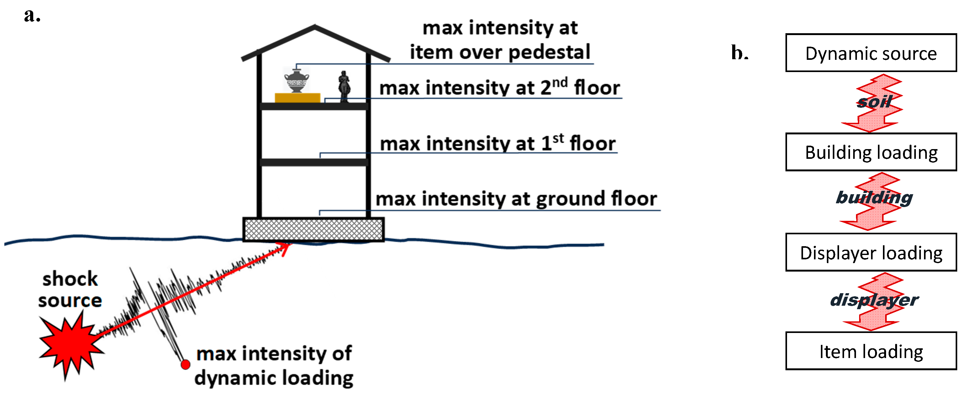
In
Figure 1a the propagation of the dynamic loading from its source to the specific location of the items exhibited within museums has been illustrated. Due to such propagation, the dynamic acceleration experienced by single items is different at each floor. Furthermore, items placed at the same floor can be exposed to different accelerations depending on their positions, directly on the floor or over pedestals/windows (see
Figure 1b). The role of the building in the propagation of dynamic excitations has been faced by several researchers [
27], and it has been included in the most recent Technical Codes, whilst few studies have been devoted to the role of the displayers [
20,
28].
In this work the role of propagation in determining the effective dynamic loading affecting art collections has been studied with reference to the National Archaeological Museum “Gaio Cilnio Mecenate” [
29] of Arezzo, which is one of the most important permanent exhibitions of archeological goods in Tuscany. A special attention has been paid to the role of the displayers in propagating dynamic loads, which has been studied by performing a dynamic monitoring, by means of seismic stations placed on the floors where the displayers are located and on the top of the displayers themselves. Furthermore, the paper presents the results of former surveys performed on the dynamic behavior of the building and its foundation soil.
In
Section 2 the National Archaeological Museum “
Gaio Cilnio Mecenate” is briefly described, with a special attention on the adopted types of displayers for exhibiting the art collections and to the potential dynamic loads which they can experience.
Section 3 briefly describes the results of former analyses, performed by some of the Authors and from further researchers, focused on the dynamic response of the foundation soil and of the building hosting the National Archaeological Museum “
Gaio Cilnio Mecenate. Finally,
Section 4 describes the survey conducted on the displayers of the Museum, and presents the obtained results.
2. Case-study: the national museum “gaio cilnio mecenate” in arezzo
2.1. The Museum and the collections
The National Archeological Museum “
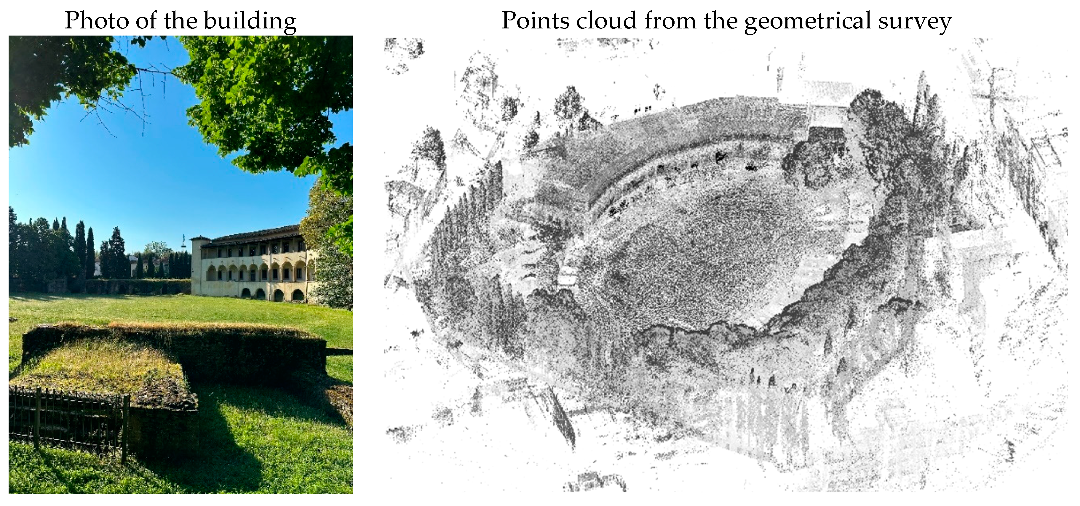
Gaio Cilnio Mecenate” is placed in the historical center of Arezzo, and it occupies part of the old San Bernardo Monastery, next to the ancient Roman amphitheater, which dates to the beginning of the II century b.C. The Monastery was commissioned by
Bernardo de’ Tolomei in 1333, and includes the remains of the amphitheater, which induced the curvy trend to the Monastery façade (see
Figure 2).
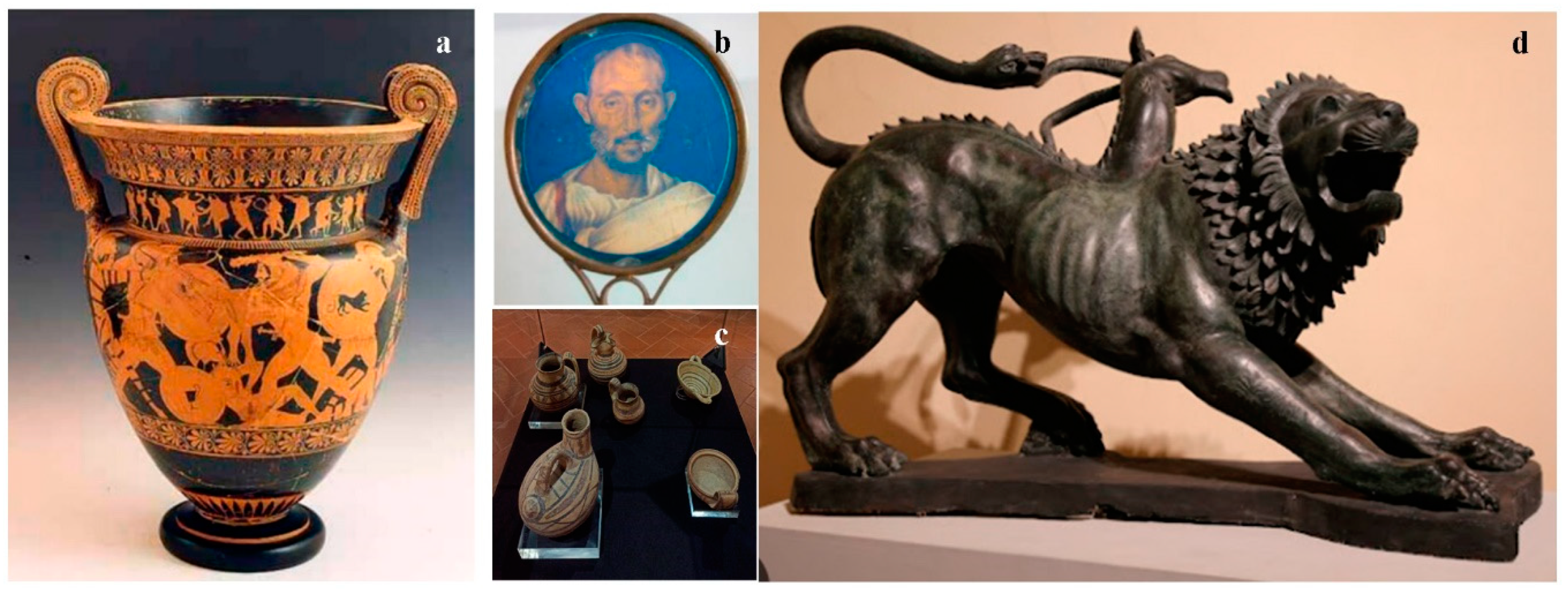
The current layout of the Museum dates to 1951, when it re-opened after the restoration due to the IIWW destruction, under the direction of superintendent Guglielmo Maetzke. It became a National Museum in 1973, and it contains about 13,000 items, including several masterpieces (see
Figure 3), such as the
Cratere di Euphronios (510 b.C.), a big red figure Athenian vase coming from a rich anonymous grave, or the medallion made through chrysography, made in gold and silver.
Most part of the exhibited items refer to the area of Arezzo, starting from the Etruscan origin, and including some thematic collections (such as bronze and jewels).
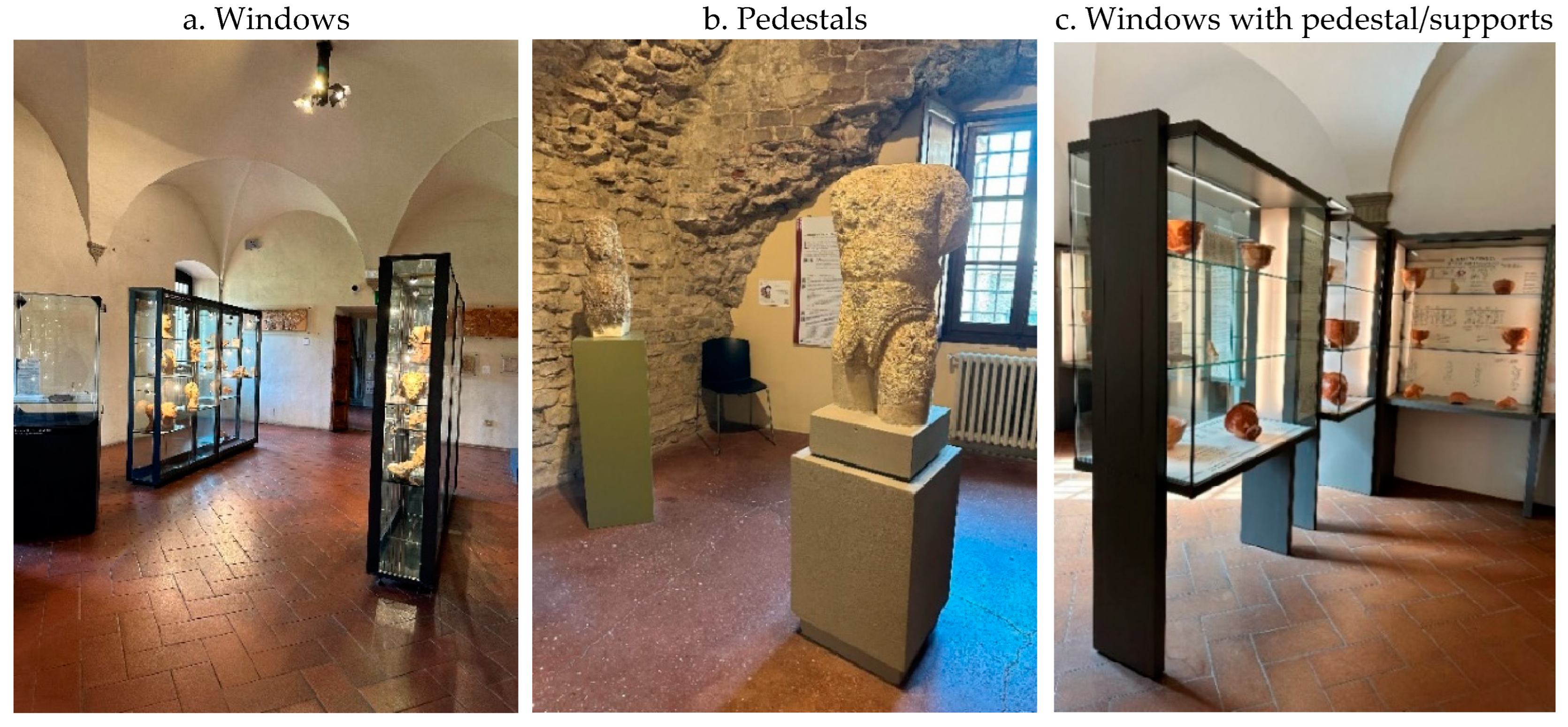
The displayers used by the Museum, shown in
Figure 4, can be distinguished in windows, pedestals and a combination of these two types, i.e., consisting of a window put on a pedestal or another type of support. In this last case, the dynamic behavior of the displayer must be studied as a combination of two different systems (pedestal and window), having different geometry and dynamical properties.
Another important distinction regards the position of the displayer within the room. Indeed, the position of the displayers just up against the wall reduces their overturning attitude. Furthermore, in this latter case, the artifact or the window can be fixed at the wall, with a consequent advantage in its seismic safety.
The glass windows present various geometrical features; most of them consist of glass windows with a steel structure, but there are even displayers with masonry basement and wood structure.
2.2. The dynamic sources of vibrations
The exhibited collections are subjected to various possible vibrations, due to the ordinary working conditions of the Museum and to “extraordinary” occurrences.
The first case includes vibrations occurring in the current use of the collections, such as the potential impacts of visitors, and the change of location of each item, due to cleaning procedures, to changes in the exhibition layout or transfer to other Museums. Even the vibrations produced by the regular vehicles traffic, and to human activities carried out in the area nearby, such as construction/demolition works, belong to this group. The second case comprehends earthquakes, landslides and explosions.
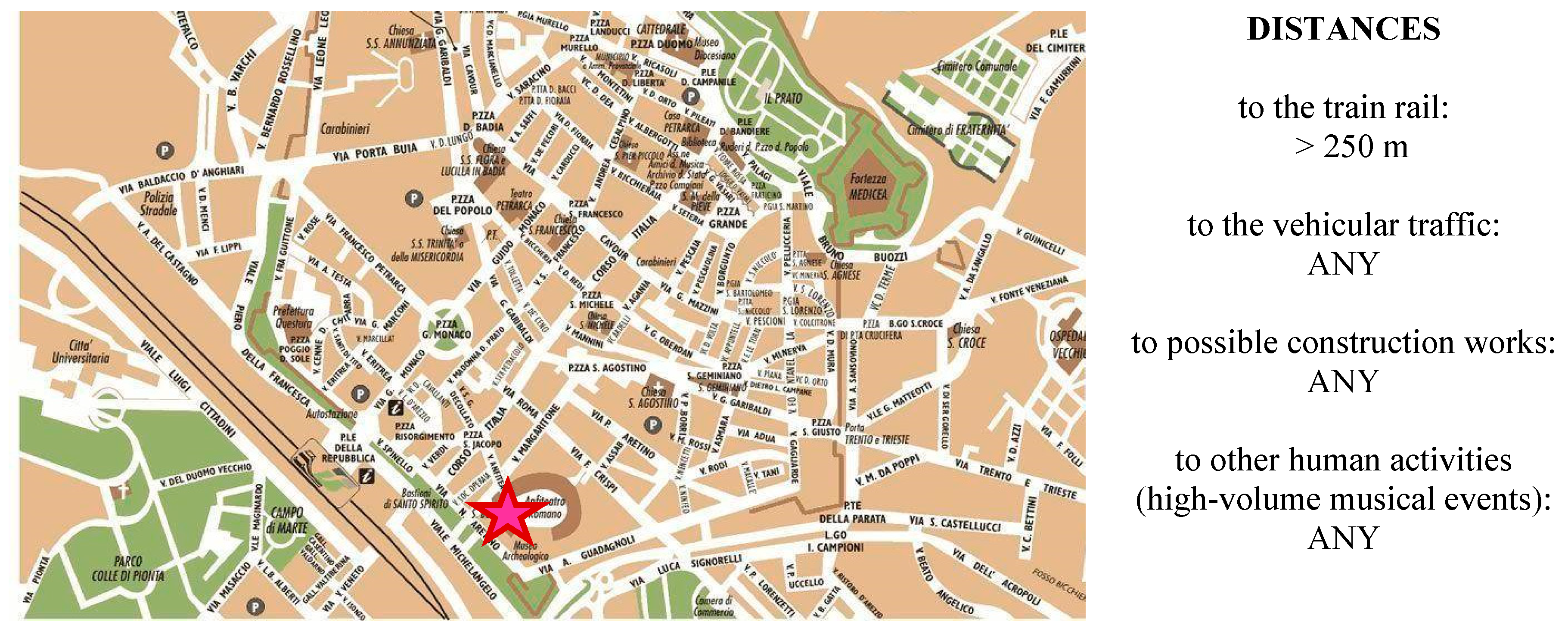
As regards the assumed case-study, the Museum is located in the center of Arezzo, therefore it is very close to all the above-mentioned vibrations sources (see
Figure 5): the vehicular paths are next to it, such as, potentially, the buildings where construction works could be made. The train rail passes through at about 250 m from the Museum. It should be mentioned that, occasionally, the amphitheater next to the Museum hosts musical events, which are very crowded and loud.
As regards the extraordinary loading, the explosions do not seem likely to occur, since the Museums is equipped with security service, and the exhibited collections cannot easily be approached. Even the landslides do not represent an effective risk, due to the flat position of the area and the consolidated soil. The only source of high intensity vibration, therefore, consists of seismic events. Arezzo is classified as subjected to “low seismic hazard” according to the current Italian Technical Code NTC 2018 [
30], with a PGA equal to 0.160g for a Return Period (RP) equal to 475 years.
Despite such low seismic hazard, Arezzo experienced various earthquakes having relevant Mercalli intensities, since Mercalli scale measures the seismic intensity in terms of damages suffered by the buildings, and the constructions are not designed for resisting to seismic actions; therefore, the seismic input results to be the most dangerous dynamic source of the Museum.
3. Former analyses performed on the dynamic properties of the museum
3.1. The foundation soil
The dynamic properties of the soil have been checked by Moscatelli
et al. in 2014 [
31], based on a former investigation on the foundation soil. In 1989 a
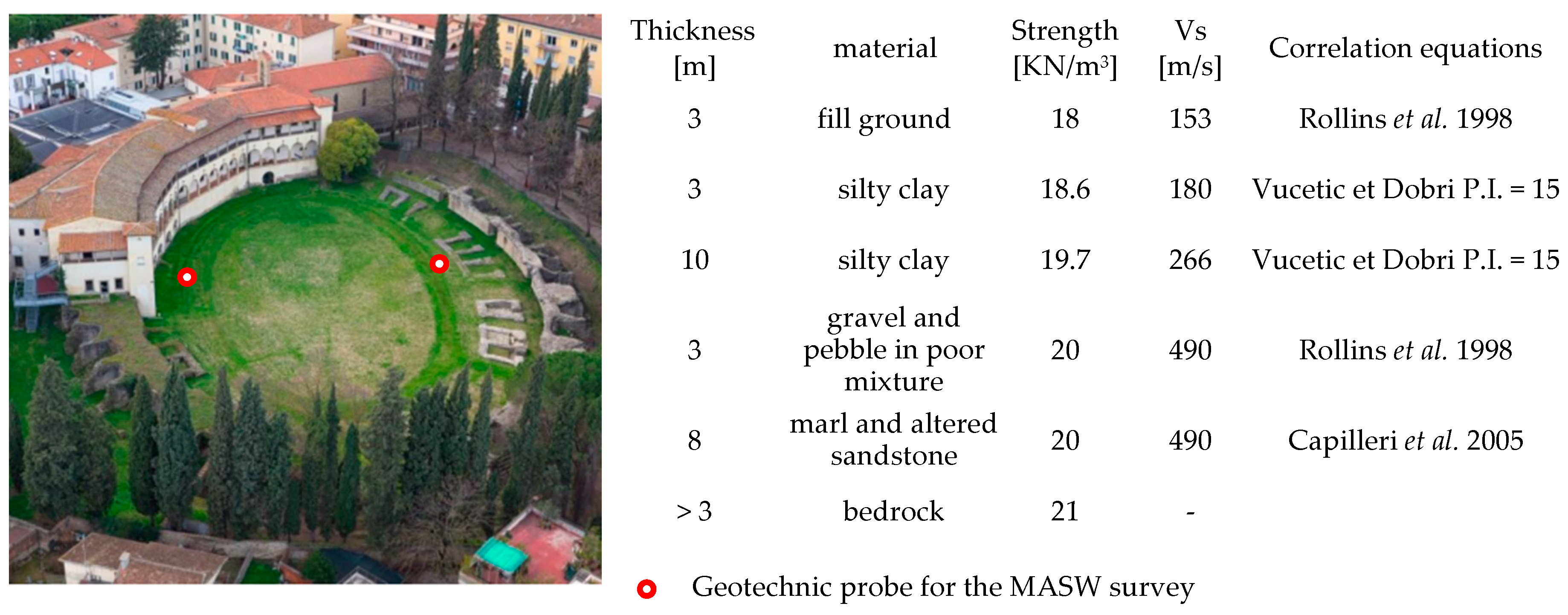
Multichannel Analysis of Surface Waves was performed, which provided the soil stratigraphy shown in
Figure 6. The shear wave velocity of the uppermost 27 meters (
vs,27), i.e. of the layer over the bedrock, resulted to be equal to 335 m/s. Therefore, according to the NTC 2018 classification, the soil has been classified as C-class. More recently, in 2010, further investigations have been performed [
32] on the most superficial layers of the soil, which confirmed such classification.
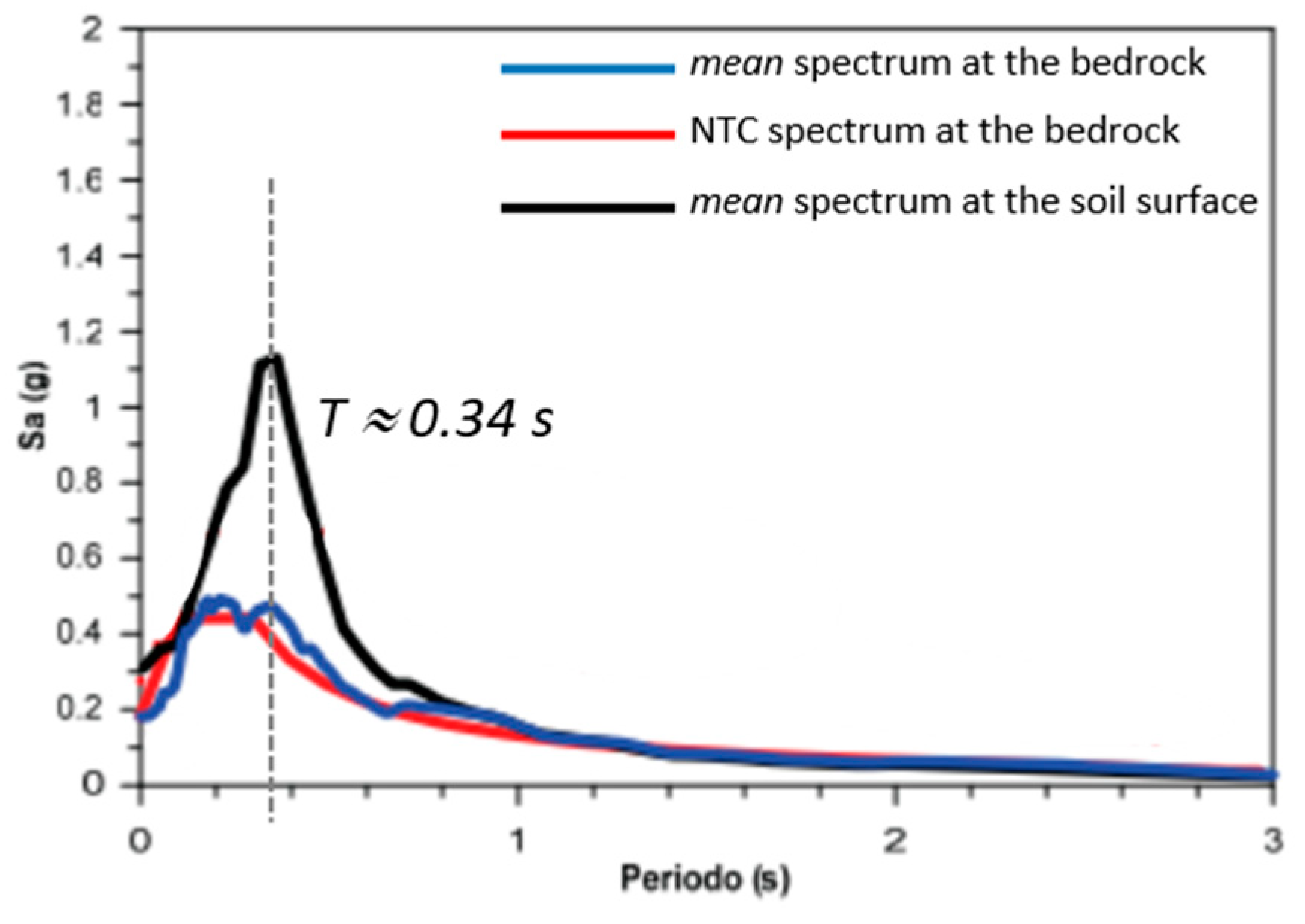
Known the soil stratigraphy, the elastic spectra at the soil surface for some
RP have been found, by performing an RSA analysis on an ensemble of 7 ground motions spectrum-compatible to the bedrock of the area.
Figure 7 shows the obtained
mean spectra, compared to ones at the bedrock and the elastic spectrum provided by NTC 2018; further information can be found in [
31]. As can be observed, the peak of acceleration occurs for a Fundamental Period around 0.32 sec, i.e. a frequency around to 3 Hz. Similar results have been provided by the survey made on the same site [
33], based on the lecture of single-station recordings of the horizontal to vertical spectral ratio (HVSR) for ambient vibrations.
3.2. The building
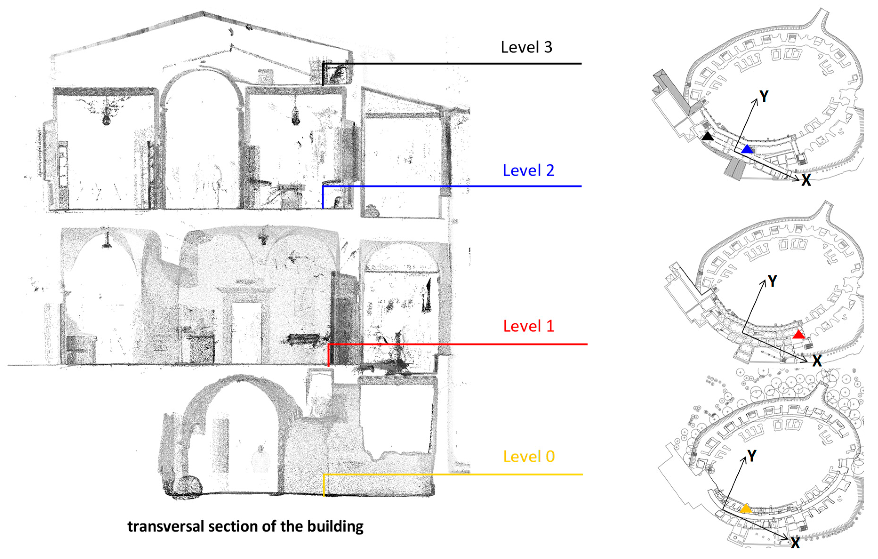
The dynamic properties of the building have been checked by performing a dynamic monitoring, i.e. by placing four seismic stations at the various levels of the structure. The experimental measurement was performed in the period between 2019, December 19 and 2020, September 29.
The dynamic loading consisted of human activity and micro-seismic accelerations; it’s worth noting that the dynamic monitoring comprehended both a “regular” period, with a normal vehicular traffic and the regular service of the Museum and a “quite-forced” period, when all the activities, including the Museum opening, stopped due to the epidemic emergency occurred in Italy. In this last period, therefore, the dynamic loading consisted of micro-seismic activity only.
The seismic stations consisted of three-axial seismometers (velocity transducer, eigenfrequency of 2 Hz, useful band between 0.1 – 40 Hz) coupled to Digital Acquisition Systems (DAS) SL06 (A/D converter 24 bit) produced by SARA electronic instruments. The horizontal components of the seismic stations were oriented, respectively, along the North-South and East-West axes, corresponding to the transverse axis and longitudinal axis of the building, and they were connected through a GPS system for the time synchronization.
Figure 8 shows the position of each seismic station; the reference seismic station is placed in the hypogeum ambulacrum of the Museum. The position of the higher seismic station, placed just under the roof, has been shown in the plan of the level 2. The stations have been indicated through a triangular symbol, whose colors correspond to as many levels.
The recorded signals have been arranged in order to get the average hourly spectra.
Figure 9 shows the average spectra along the three monitored directions. For sake of legibility, horizontal and vertical spectra have been represented through different scales. As can be observed, along the two horizontal directions, the dynamic response of the building evidences two peaks very closed to each other, respectively equal to 3.75 Hz along the longitudinal (X) direction and 3.92 Hz along the transverse (Y) direction. It’s worth noticing that the main vibrational axes cannot be clearly found, since the building has a very complex geometry and the seismic stations are not vertically aligned.
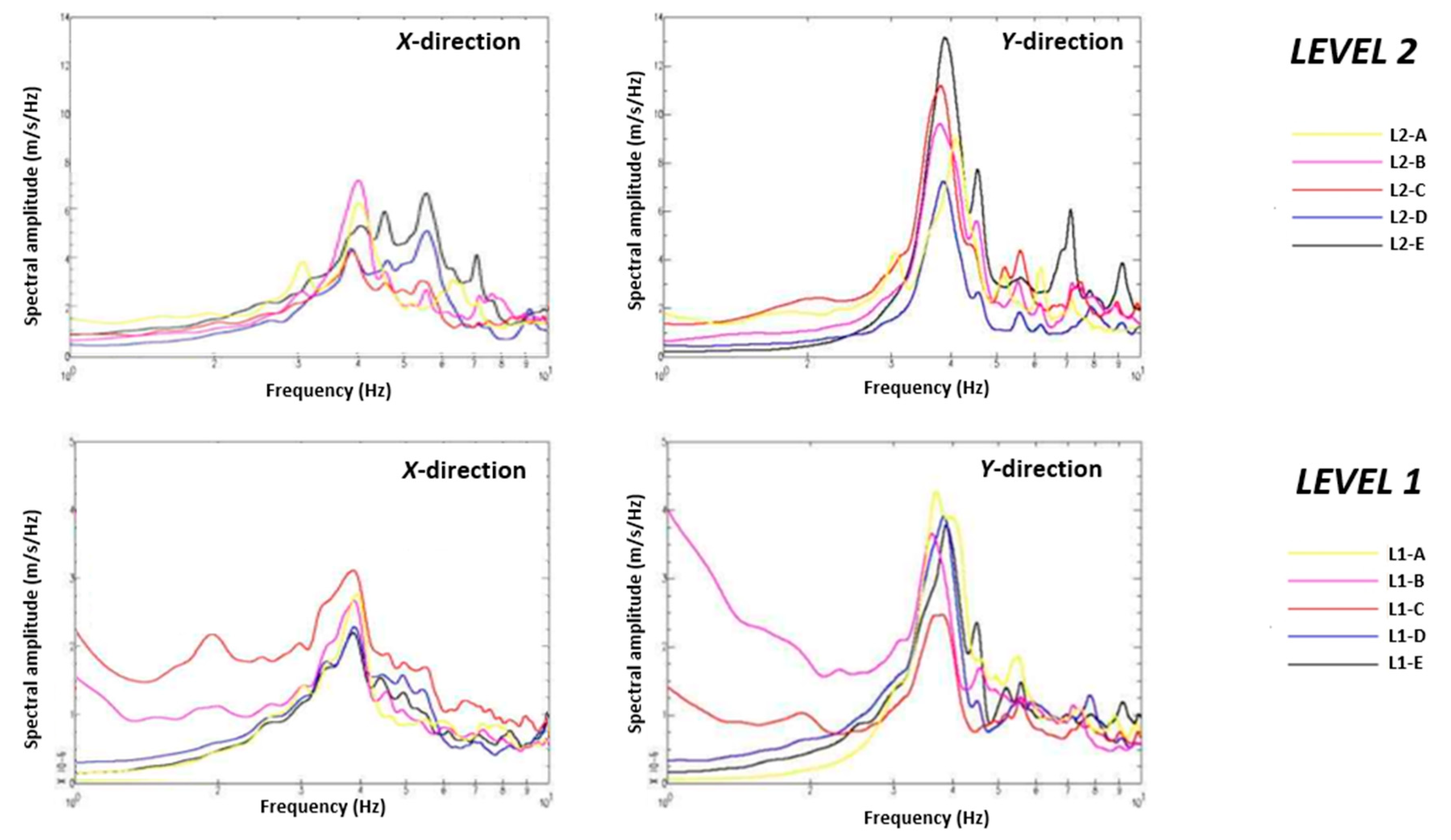
The dynamic response of the building has been object of a further investigation: five seismic stations have been placed at each of the main levels (L1, L2), to check the torsional effects related to its dynamic response. The dynamic response of each story has been recorded for 40 minutes only, by using seismic stations of the same type of the other survey.
Figure 10 shows the position of the seismic stations used in this investigation, whilst
Figure 11 shows the obtained average spectra. It should be noticed that, for sake of legibility, different representation scales have been used for the two levels.
The obtained average spectra are consistent to the ones already found in the former analysis. All the peaks along the Y-direction occur in the range of frequencies between 3.65 and 3.85 Hz and those along the X-direction are around 4.05 Hz. For each level and direction, the scatter between the five spectra around the peak of frequency expresses the sensitivity of the building to torsional effects. As can be seen, the differences between the lectures of the same seismic stations are larger at the second level.
4. The dynamic experimental campaign
4.1. The performed experimental campaign.
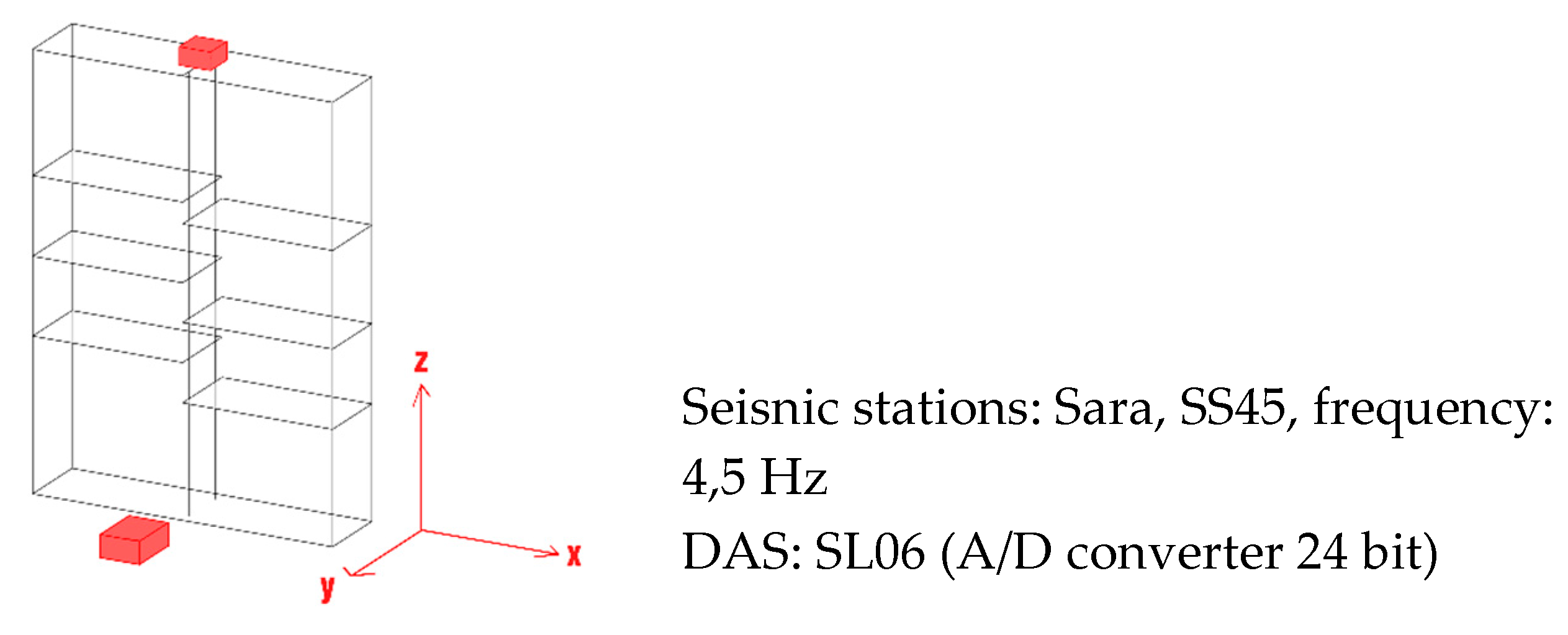
The experimental campaign consists of monitoring the windows through three-axial seismometers respectively placed at the base and at the top of the windows. The seismometers have a proper frequency of 4,5 Hz coupled to Digital Acquisition Systems (DAS) SL06. The two seismometers are synchronized through GPS connection. In all cases, the Y-direction has been assumed along the shorter side of the window, as shown in
Figure 12.
The data have been recorded at 100 sps and arranged before processing, to correct the instrumental curve of the sensor. The recordings have been performed in the operational time of the Museum, i.e. with visitors potentially walking around the windows.
The results have been expressed in terms of peak particle velocity (PPV) and peak component particle velocity (PCPV), which are the quantities adopted in the main International Technical Codes [
34,
35,
36,
37] to check the vibrational behavior of buildings. Unfortunately, such Codes provide reference thresholds only for constructions, whilst the acceptable conditions for artifacts are not codified yet. PPV and PCPV are defined according to the following expressions:
-peak particle velocity (PPV), defined as maximum value of the modulus of velocity vector in a three-dimensional space:
-peak component particle velocity (PCPV), defined as maximum value of the modulus of one of the orthogonal components measured simultaneously:
where
X,
Y and
Z are the three spatial components of the velocity vector.
Before proceedings to determine the response parameters, the proper frequencies of the displayers have been found. To this purpose, the FFT of the signal have been determined, according to the procedure described in Morelli
et al. [
38]. The
mean FFT have been found by averaging the single values found for time-intervals of 120 s; in this way, each result is described through
mean,
standard deviation and
coefficient of variation.
4.2. The checked displayers.
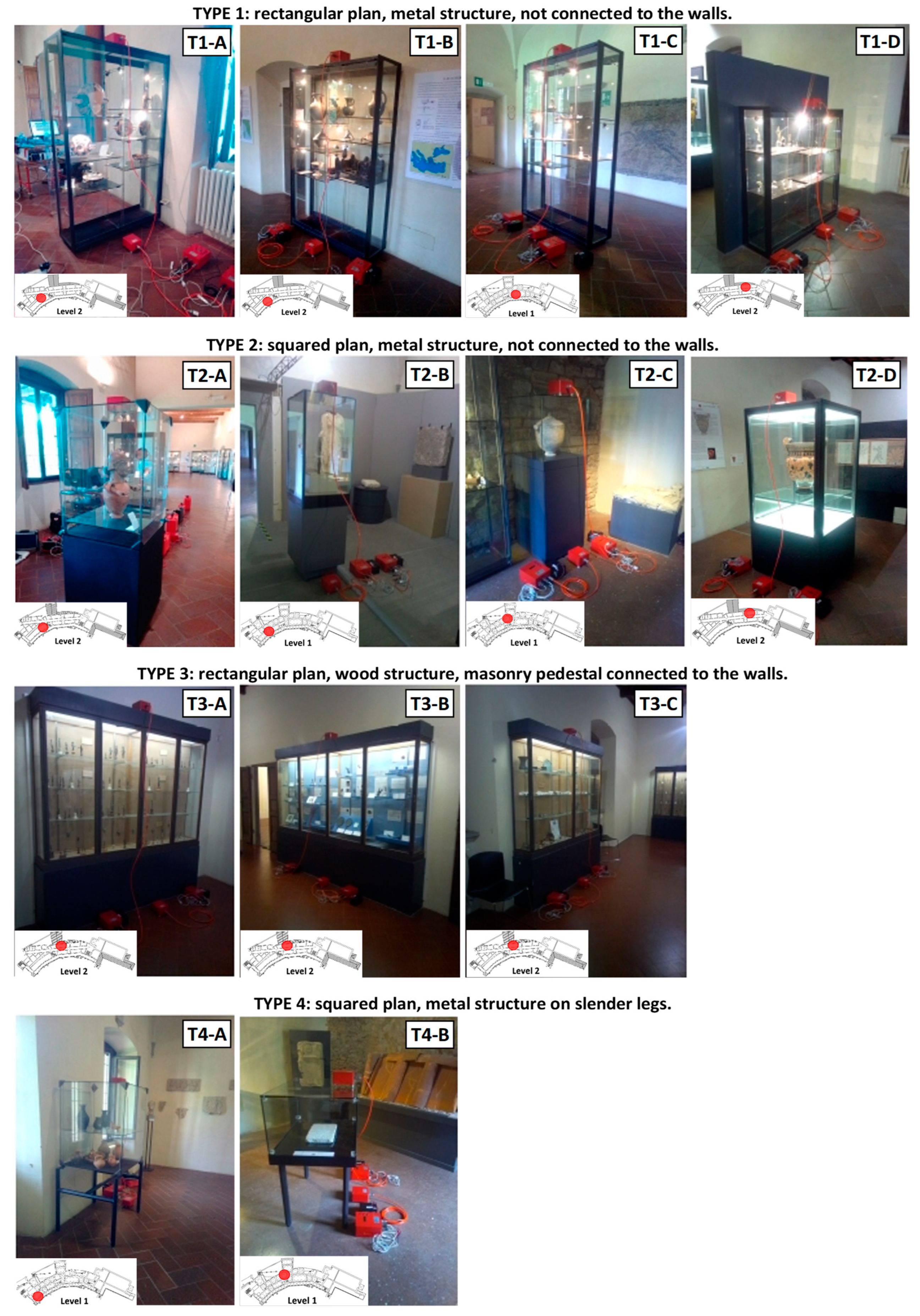
The dynamic monitoring involves 13 displayers, which differ from each other for geometry (and slenderness), dimensions, material and position within the building. In order to better understand their dynamic properties, they have been organized in four groups, having a relative homogeneity of features.
The first considered group collects four windows made of glass and metal, with a rectangular plan. They have one plan dimension much larger than the other one, and they have various positions respect to the building’s walls. The second group consists of four glass displayers with a squared plan and rigid pedestal of various heights. The third group consists of three glass displayers, whose pedestals are made of masonry and connected to the structure. Finally, the fourth group collects two glass displayers supported by metal supports.
Figure 13 shows the checked displayers, together with their position within the building and the assumed classification.
4.3. Results
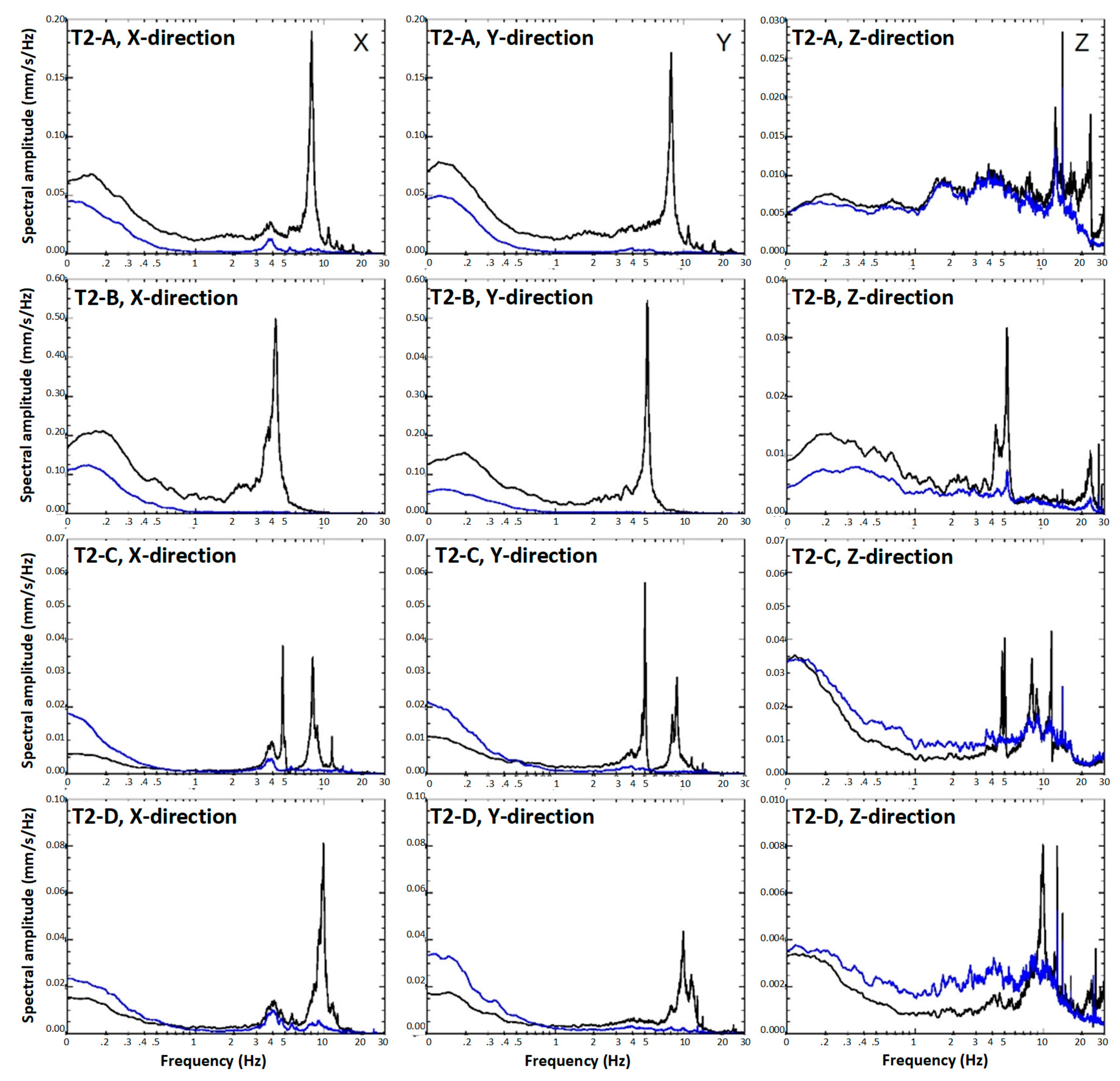
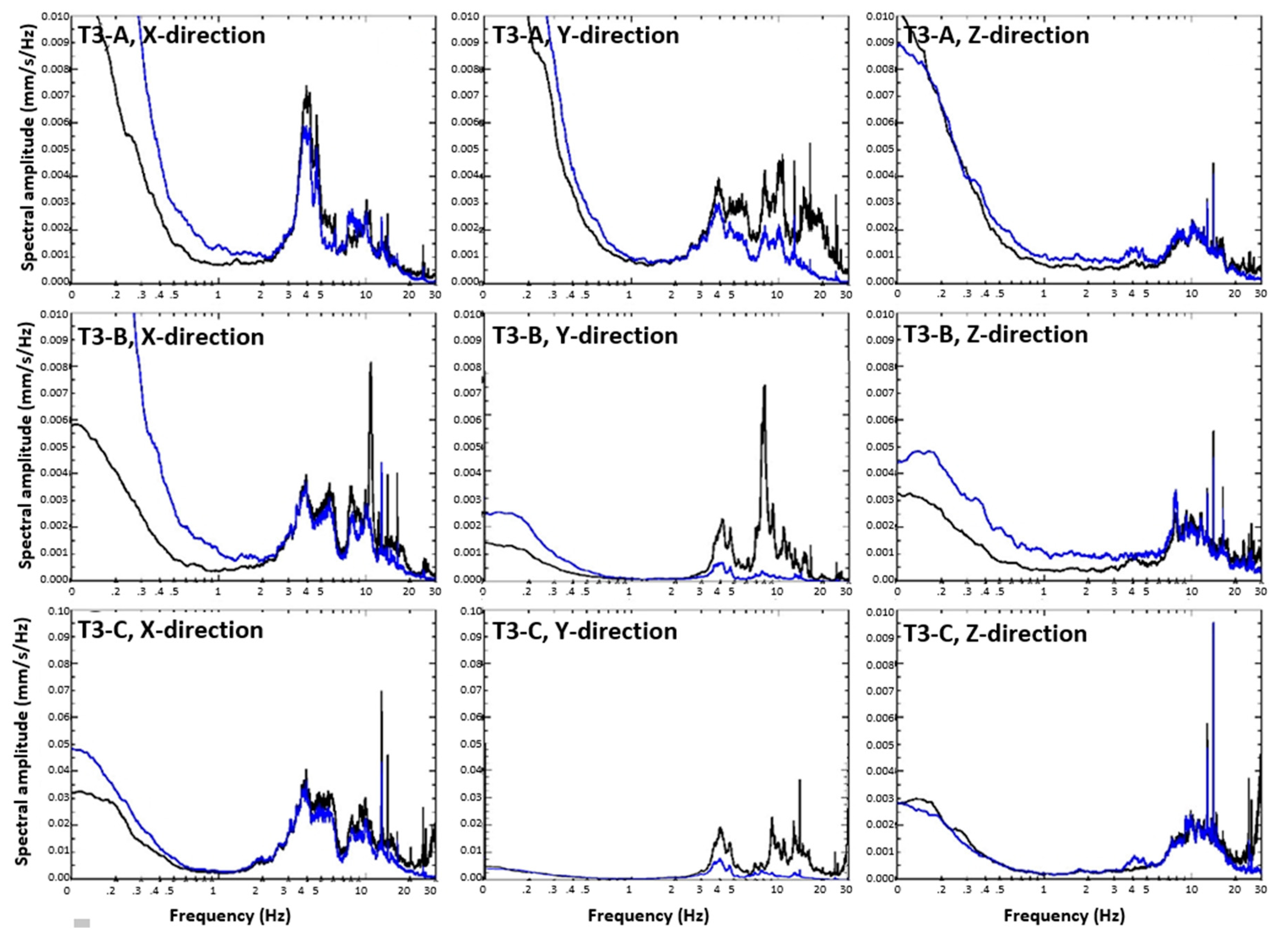
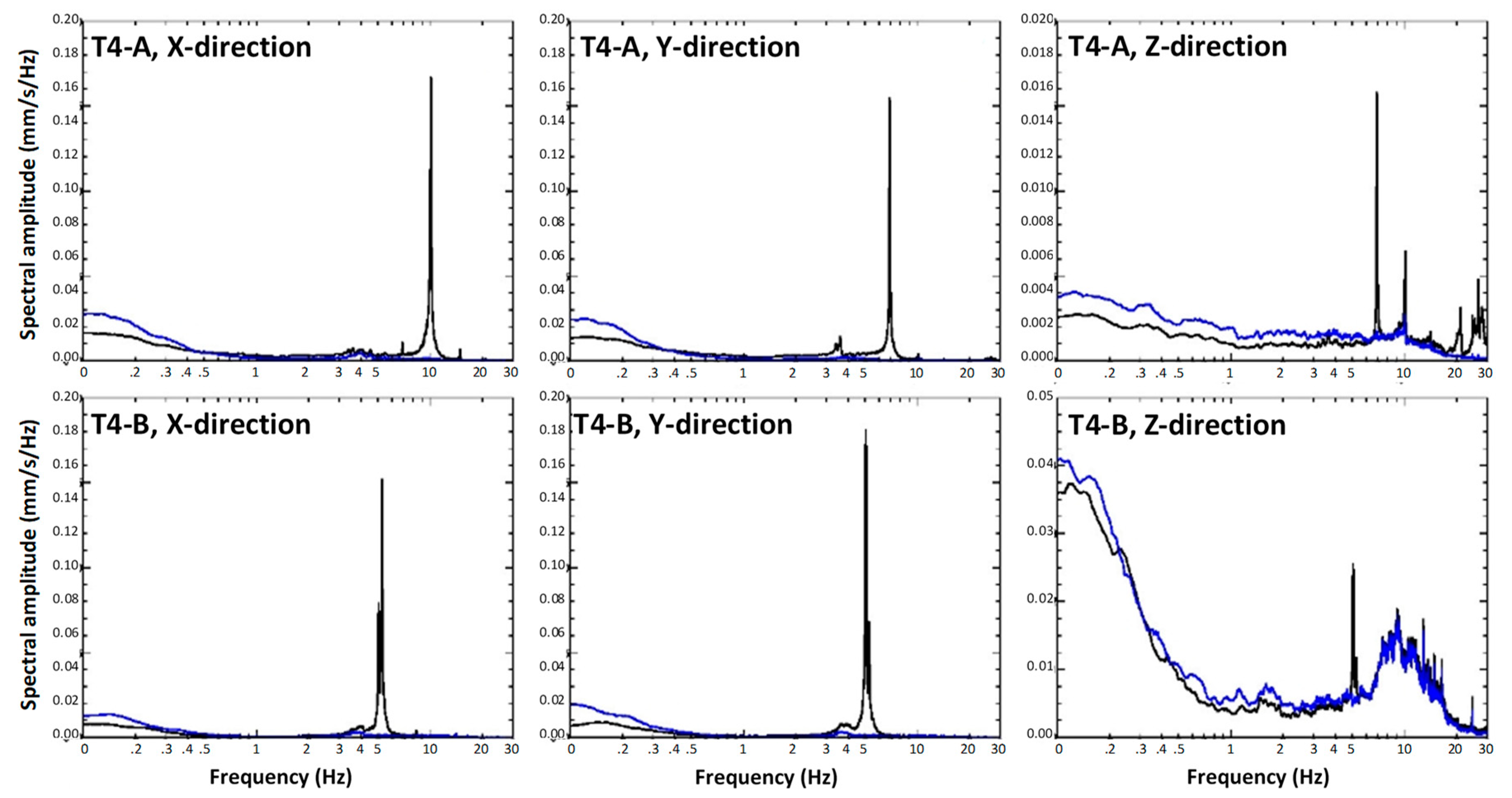
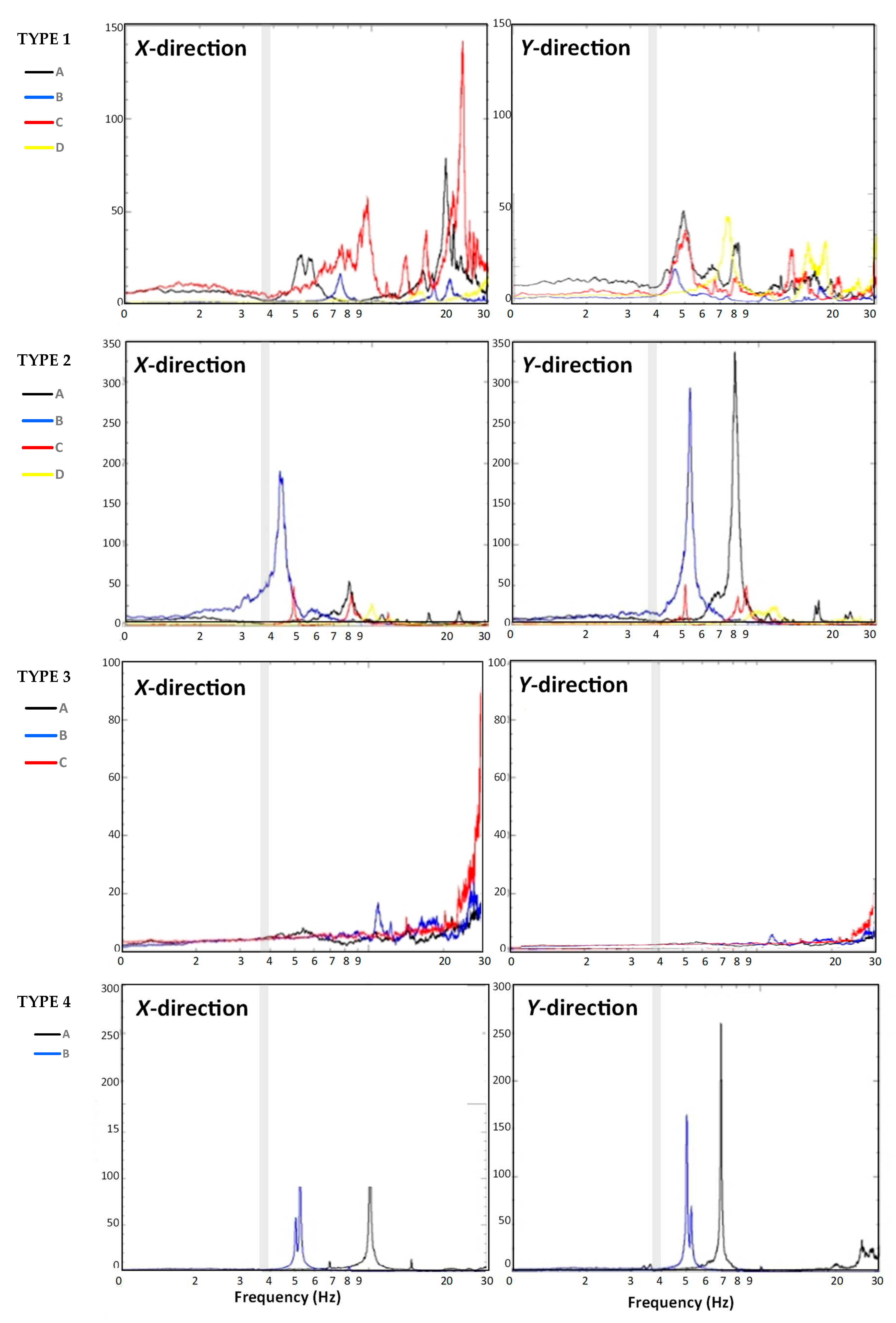
The first response quantities checked in the analysis are the mean spectra.
Figure 14,
Figure 15,
Figure 16 and
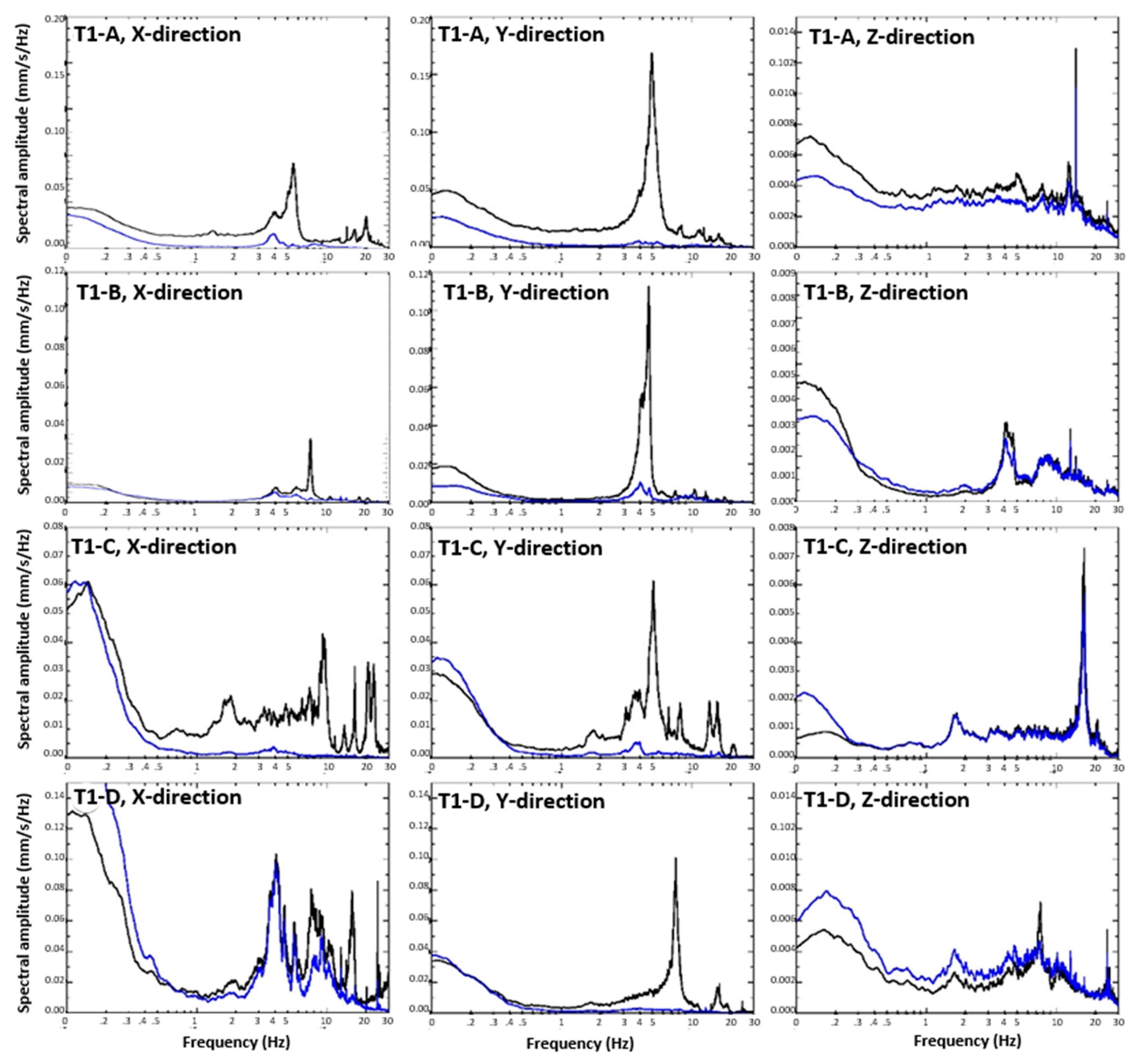
Figure 17 show the mean spectra obtained for each monitored displayer along the three directions. In each figure, two spectra have been shown, respectively representing the signal at the base of the displayer (blue line) and on the top (black line). The diagrams have been grouped by type to better evidence the similitudes between the samples. For sake of legibility, the representation scale has not been unified, since the values of the spectral amplitude varies very much from each other. For each displayer, however, the same representation scale has been adopted for both the horizontal directions. The amplitude along the vertical direction is about one order of magnitude lower than the horizontal ones.
The Type 1 displayers (see
Figure 14) evidence different dynamic responses along the two horizontal directions, since the two lengths of the plan are very different from each other and, consequently, even the slenderness results to be different. As regards the dynamic response along the main direction (Y), all the observed displayers evidence a proper frequency close to 5 Hz. The amplitude peaks experienced by the four displayers along the Y direction ranges between 0.18 mm/s/Hz (T1-A) and 0.06 (T1-C). It should be noticed that the sample T1-A has not any constraints along the Y direction, and it is located at the Level 2, whilst the displayer T1-C is placed at the Level 1.
Figure 15 shows the mean spectra of the Type 2 displayers, having a squared plan. In this case, the amplitude peaks are quite similar along the two horizontal directions. The properties which mostly affect the dynamic response of these samples are the behavior of the support floor and the technology of the displayer. The dynamic behavior of the floor is related to its level within the structure. Moreover, the room where the displayer T2-B is located has a floating floor, i.e. a further wooden floor placed over the structural one. For this reason, such floor is much more flexible than the other ones, and the displayer placed in such room evidences a higher dynamic response than all the others. As regards the technology of the displayers, as can be noticed in
Figure 13, the windows of the samples T2-A and T2-C are made in glass only, whilst in the others (T2-B, T2-D) the glasses of the window are framed by a metal structure, which stiffens the whole displayers, reducing their spectral amplitude.
Figure 16 shows the mean spectra of the displayers belonging to the Type 3, the stiffer of the considered ones. Indeed, the pedestals are made in masonry, and they are fixed to the walls. The three displayers are at the same level (Level 1) and in the same room, despite having different orientations. As can be noticed, they evidence spectra very similar to the ones of the building, especially along the longitudinal and the vertical directions. Some differences can be found in the transversal response of the displayers, i.e. the
X-direction of the T3-A and the
Y-direction of the T3-B, T3-C due to the not perfect fixing to the adjacent wall.
Finally,
Figure 17 shows the mean spectra of the Type 4 displayers. They are the more flexible ones, due to the slender legs supporting the windows, and they are not fixed at the walls; their amplitudes overcome 15 mm/s/Hz despite both of them are placed at the 1
st level. As should be expected, they have a similar amplitude in the two horizontal directions; the frequency of T4-A is different along the two directions, since the support has a stiffener along one direction only.
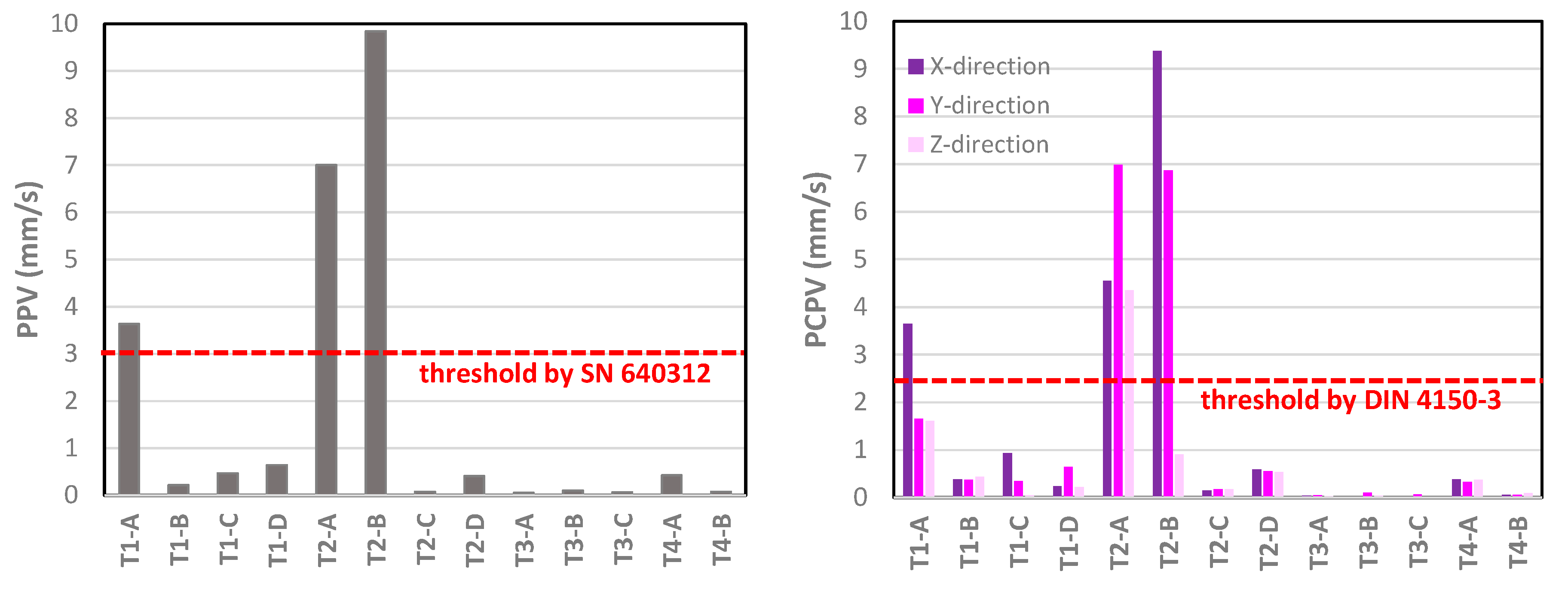
The response quantities PPV and PCPV have been found for each monitored displayer by considering the maximum value of the velocity vector each 5s time interval, according to the functions (1) and (2) reported in § 4.1.
Figure 18 shows the peaks of PPV (
Figure 18a) and PCPV (
Figure 18b), respectively, for the checked displayers. In the figures, the values provided by the analysis have been shown together with a threshold provided by International Codes. As mentioned in § 4.1, there are not limit values for artifacts; the reference thresholds, therefore, refer to historical buildings, in case of persistent/permanent excitations. Such values should be considered as a general order of magnitude reference, without any purpose of acceptance assessment.
The PPV peak values experienced by the displayers vary in a range between 0.05 (T3-A) and 9.84 (T2-B). It should be noticed that the displayer T2-B, which evidences the larger values of PPV and PCPV, is placed over the floating wooden floor, which, clearly, largely amplifies its dynamic response. Even the displayer T2-A achieves similar values of the response quantities. It results to be the most sensitive to vibrations among the considered ones, due to its position (second level) and its technology: the upper glass window has not supported by any metal structure.
The velocity peaks experienced by most of the displayers are lower than the limits provided by the Codes for the buildings’ roof. However, three of them exceed the thresholds, resulting more than three times larger than the buildings’ acceptance limit. It’s worth noting that the monitoring has been made during a normal working time of the Museum; it is possible, therefore, that the perturbance constituting the dynamic loading was not the same for all the checked displayers, and that the Museum can be more crowded, with a possible increase of the dynamic excitation.
4.3. Assessment of the dynamic property of the exposition system
As a result of the performed survey, the amount of amplification performed by the displayers has been assessed.
Figure 19 shows, as a function of the system’s frequency, the spectral ratio between the amplification at the top of the displayers and the one at their base. Only the two horizontal directions have been shown, since they are the most meaningful in the current analysis. The range of the proper frequencies of the building in the two directions has been evidenced in grey, to better understand the relationship between the dynamic properties of building and displayers. The building range indicated in the figure is the same along the
X and
Y directions, since the axes considered for each displayer could not coincide with the ones of the building.
The larger spectral amplifications occur at the proper frequency of the displayers. As can be noticed, the maximum amplifications of the displayers do not occur at the same frequency of the building response, except for the displayers whose masonry pedestal is fixed to the walls (Type 3). In this case, the displayers present amplifications at different frequencies: the first peak occurs at the proper frequency of the pedestal (which is the same than the building), whilst the other ones refer to the frequency of the upper window.
The values of the amplification largely vary as a function of the displayer type. The larger amplifications (almost 350) affect the T2 displayers, whilst the T3 displayers evidence the lower amplification (below 20).
Figure 20 shows the propagation flow, already proposed in
Figure 1b, together with the values found for the proper frequencies along the horizontal directions of each system involved in the propagation. Foundation soil, building and displayers result to have different frequency, with the consequent absence of resonance phenomena.
5. Conclusions
In this work an experimental survey has been conducted on some displayers used for exhibiting archeological items at the National Museum “Gaio Cilnio Mecenate” in Arezzo.
Four types of displayers have been selected, differing from each other for geometry, slenderness, technology and placement within the Museum. The survey consisted in monitoring the dynamic response of the displayers through a proper placement of 3-d seismic stations. The arrangement of the recorded data lead to determine the mean spectra of the displayers along the three monitored directions, together with their proper frequencies and amplitude.
The investigation provided very different mean spectra for the examined systems, with spectral amplitudes varying from 0,005 mm/s/Hz for the stiffer displayer (T3-A) and almost 0.20 for the slender ones (T1-A, T2-A, T4-A, T4-B). By comparing the dynamic spectra at the base and at the top of each displayer, the propagation made by each of them along the three directions have been found for each frequency. Even this response parameter resulted to be largely affected by the properties of the displayers and their location.
The frequencies found for each displayer have been compared to the ones of the building and the foundation soil, provided by former analyses. Such comparison evidenced that there is not any resonance threat, since the three propagation systems have different frequency content.
Finally, the PPV and PCPV have been determined for the monitored displayers and compared to the thresholds provided by the International Codes for historical buildings. Some of the displayers presented high values of PPV and PCPV, suggesting a potential vulnerability to dynamic loading.
Since the monitoring has been made during a normal working time of the Museum, it is possible that the perturbance constituting the dynamic loading could be larger at the occurrence of special events proposed by the Museum, as well as the high touristic season. Therefore, further investigations should be carried out, to check the displayers which evidenced higher propagations in a wider range of operational situations of the Museum.
Acknowledgments
We are grateful to the National Museum “Gaio Cilnio Mecenate” and to Maria Gatto for the availability and the precious collaboration.
References
- Andreatta M, Coppola F, Modelli A, Santopuoli N, Seccia L (2017). Proposal for a new environmental risk assessment methodology in cultural heritage protection. Journal of Cultural Heritage 23: 22-32, Elsevier Masson France.
- Lo Russo S, Natali A, Matteucci C, Palla F, Apicella SA, Pianese C, Bertolami C, Barresi G, Di Carlo E (2015). La gestione del rischio nel settore dei Beni Culturali: Musei, Biblioteche e Archivi, Mimesis Edizioni, Milano.
- Costain C (1994). Framework for preservation of Museum collections. CCI Newsl. 14, 1-4.
- Podany J (2017). When Galleries Shake: Earthquake Damage Mitigation for Museum Collections. Getty Publications, pp 248. ISBN 978-1-60606-522-8.
- Lowry MK, Farrar BJ, Armendariz D, Podany J (2007). Protecting Collections in the J. Paul Getty Museum from Earthquake Damage. WAAC Newsletter 29: 16-23.
- Domaneschi M, Tanganelli M, Viti S, Cimellaro GP (2020). Damage risk assessment of historical asset using laser scan and finite element. Procedia Structural Integrity, vol. 29, p. 183-191, ISSN: 2452-3216. [CrossRef]
- Domaneschi M, Tanganelli M, Viti S, Cimellaro GP (2021). Vulnerability of art works to blast hazard: the Fountain of Neptune in Florence. In: COMPDYN 2021, ATENE, 27–30 June 2021, COMPDYN 2021, pp. 1-10.
- Tanganelli M, Viti S, Cimellaro GP, Domaneschi M (2020). Developing a laboratory facility to assess friction coefficients of standing samples. Procedia Structural Integrity, vol. 29, pp. 142-148, ISSN:2452-3216.
- Viti S, Reinhorn AM (2020). Monumental buildings used as museums: protection or danger for the artifacts? Procedia Structural Integrity, vol. 29, pp. 40-47, ISSN:2452-3216.
- Saeed ES, Giresini L, Niglio O, Graziotti F (2023). Human-induced vibrations on Museum artefacts: literature review and calculation example. 9th ECCOMAS Thematic Conference on Computational Methods in Structural Dynamics and Earthquake Engineering (COMPDYN), M. Papadrakakis, M. Fragiadakis (eds.). Athens, Greece, 12-14 June.
- Podany J (2015). An overview of Seismic Damage Mitigation for Museums. International Symposium on Advances of Protection Devices for Museums Exibits. April 13-17, Beijing & Shanghai.
- Podany J and Metro B (1990). Survey of Artifacts Damage in the Bay area Museums. Earthquake spectra, Journal of the Earthquake Engineering Research Institute, vol. 6 (May) supplement, edited by L. Benuska.
- Podany J (1987). Advances in the Reassembly of Large Scale Sculpture at the J. Paul Getty Museum. In “Recent advances in the Conservation and Analysis of Artifacts. Preprint from the Jubilee Conservation Conference. London: University of London, Institute of Archeology (July 6-10 1987): 375-81.
- Lelli S, Gatto M, Tanganelli M, Viti S (2023). Seismic vulnerability of museums’ collections: a case-study. 9th ECCOMAS Thematic Conference on Computational Methods in Structural Dynamics and Earthquake Engineering (COMPDYN), M. Papadrakakis, M. Fragiadakis (eds.). Athens, Greece, 12-14 June 2023.
- Viti S, Tanganelli M (2019). Resimus: A research project on the seismic vulnerability of museums’ collections. In: 7th International Conference on Computational Methods in Structural Dynamics and Earthquake Engineering, COMPDYN 2019, National Technical University of Athens, vol. 2, pp. 2819-2829, ISBN:978-618-82844-7-0.
- Thickett D (2002). Vibration damage levels for museum objects. Proc. ICOM Committee for Conservation 13th Triennial Meeting Rio de Janeiro, 1-902916-30-1, James & James (Science Publishers) Ltd.
- Valach J, Wolf B, Urushadze S, Paulova E, Stefcova P (2022). Quantification of mechanical loads induced by traffic and visitors on museum collections placed in a cultural heritage building, C.A. Proc. Sustainable City 2022, Brebbia, Wessex Institute of Technology, UK.
- Johnson P and Hannen WR (2015). Vibration Limits for Historic Buildings and Art Collections. Engineering.
- Johnson A, W. Robert Hannen WR, and F. Zuccari F (2013). Vibration Control during Museum. Construction Projects,” Journal of the American Institute for Conservation 52 no. 1 (2013): 30-47.
- Wei W and Dondorp E (2020). Testing to Determine Allowable Vibration Limits at a Natural-History Museum in the Netherlands, APT Bulletin: The Journal of Preservation Technology, Vol. 51, No. 4, Special Issue: Mitigating Vibration Damage (2020), pp. 19-26.
- Ciampoli M, Augusti G (2000). Vulnerabilità sismica degli oggetti esibiti nei musei: interventi per la sua riduzione. In: Vulnerabilità dei beni archeologici e degli oggetti esibiti nei musei. A cura di D. Liberatore, CNR-GNDT (in Italian).
- Borri A, Grazini A (2006) Diagnostic analysis of the lesions and stability of Michelange-lo’s David, JCH 7, 273–285.
- Berto L, Favaretto T, Saetta A, Antonelli F, Lazzarini L (2012). Assessment of seismic vulnerability of art objects: The “Galleria dei Prigioni” sculptures at the Accademia Gallery in Florence, J C H 13, 7–21.
- Dimitrakopoulos EG, Dejong MJ (2012). Revisiting the rocking block: closed-form solu-tions and similarity laws. Proc. R. Soc. A 468, 2294–2318.
- Viti S, Pintucchi B, Rotunno T, Tanganelli M (2020). The seismic analysis of Cerere at the Museum of Bargello, Bulletin of Earthquake Engineering. [CrossRef]
- Trovatelli F, Barbagallo F, Marino EM, Tanganelli M, Viti S (2023). Modeling Marble Artworks: The Statue “Oceanus” by Giambologna. In: Florence Heri-Tech 2022, Springer Nature Switzerland AG., vol. 3rd International Conference on The Future of Heritage Science and Technologies, Florence Heri-Tech 2022, pp. 60-69, ISBN:978-3-031-17593-0.
- Azzara RM, Pellegrini D, Cardinali V, Viti S, Tanganelli M (2023). Assessment of the Acceleration Floor Spectra Through Dynamic Identification: The Museum of Bargello in Florence. In: 17th World Conference on Seismic Isolation, WCSI 2022, Springer Science and Business Media Deutschland GmbH, vol. 309, pp. 1010-1021, ISBN:978-3-031-21186-7.
- Cosenza E, Di Sarno L, Maddaloni G, Prota A (2015). Shake table tests for the seismic fragility evaluation of hospital rooms. Earthquake Engineering and Structural Dynamics 44(1).
- AA. VV. (1987). Il Museo Archeologico Nazionale G. C. Mecenate in Arezzo, Ed., Fi-renze, Arti Grafiche Giorgi e Gambi Srl per conto di CRF Firenze (in Italian).
- NTC (2018). Decreto del Ministro delle Infrastrutture del 17 gennaio 2018, Nuove norme tecniche per le costruzioni, Italia (in Italian).
- Moscatelli M, Pagliaroli A, Pileggi D, Simionato M, Scasserra G, Giallini S, Sirianni P, Stigliano F (2014). CNR-IGAG Arezzo, Museo Archeologico Nazionale – Analisi della risposta sismica locale, Convenzione IGAG-MiBACT, Verifica della sicurezza sismica dei Musei Statali.
- Cara F, Di Giulio G, Bergamaschi F, Azzara RM (2011). Misure geoelettriche e di rumore sismico ambientale per la caratterizzazione dei terreni superficiali all’interno dell’anfiteatro romano di Arezzo, Rapporto interno INGV.
- Acerra C, Aguacil G, Anastasiadis A, Atakan K, Azzara R, Bard PY (2004). Guidelines for the implementation of the H/V spectral ratio technique on ambient vibrations measurements, processing and interpretation. European Commission–EVG1-CT-2000-00026 SESAM.
- Swiss Standards Association, “Effects of Vibration on Construction,” SN 604 312a (2013). J. Studer and A. Suesstrunk, “Swiss Standard for Vibrational Damage to Buildings,” Proceedings of 10th International Conference of Soil Mechanics and Foundation Engineering (Stockholm, 1981).
- DIN 4150-3 (1999). Structural Vibration. Part 3: Effects of Vibration on Structures. DIN Deutsches Institut für Normung: Berlin, Germany.
- British Standards Institute (1993). BS 7385 Evaluation and Measurement for Vibration in Buildings, Part 1: Guide for measurement of vibrations and evaluation of their effects on buildings,” 1990, and “Part 2: Guide to damage levels from groundborne vibration”.
- ISO 8569 (1996). Mechanical vibration and shock – Measurement and evaluation of shock and vibration effects on sensitive equipment in buildings.
- Morelli A, Azzara RM, Cavaliere A, Zaccarelli L (1994). Normal Mode Analysis of Ambient-Noise Induced Free Oscillations of a Slender Medieval Masonry Tower in Bologna (Italy).AGU Fall Meeting Abstracts 2014, S42B-02.
|
Disclaimer/Publisher’s Note: The statements, opinions and data contained in all publications are solely those of the individual author(s) and contributor(s) and not of MDPI and/or the editor(s). MDPI and/or the editor(s) disclaim responsibility for any injury to people or property resulting from any ideas, methods, instructions or products referred to in the content. |
© 2023 by the authors. Licensee MDPI, Basel, Switzerland. This article is an open access article distributed under the terms and conditions of the Creative Commons Attribution (CC BY) license (https://creativecommons.org/licenses/by/4.0/).
