Preprint
Article

Composite Scattering Computation from Multiple Dielectric Targets of One-Dimensional Fractal Sea Surface Using MOM

Altmetrics

Downloads

55

Views

17

Comments

0

This version is not peer-reviewed

Submitted:

18 September 2023

Posted:

20 September 2023

You are already at the latest version

Alerts
Abstract
Bistatic scattering coefficient have important application of ocean active microwave remote sensing. In this paper, a general expression of the composite scattering coefficient for multiple dielectric targets of one-dimensional fractal sea surface is derived by MOM method. Secondly, the bistatic scattering coefficient is computed, there are two class missile targets and one class ship target of one-dimensional fractal sea surface, and the influence of the water dielectric constant, fractal dimension, wind speed, the target dielectric constant and spatial position is discussed, and the corresponding conclusions are given. The proposed algorithm is able to solve some composite scattering problems, such as “dielectric or conductive object + rough surface”, “dielectric or conductive floating object +rough ”and it has certain generalization and reference.
Keywords: 
Subject: Engineering  -   Control and Systems Engineering

1. Introduction

Over the past years, with the emergence of new weapons such as ultra-low-altitude, ultra-high-speed missiles and stealth aircraft flying sea-skimming [1], the research of the composite electromagnetic scattering for target and the sea surface is gradually followed with interests [2,3]. When there is a target above or on the sea surface, an additional coupling scattering field is expected to generate due to the electromagnetic interaction between the target and the sea surface, adding to the difficulties of target measurement, tracking and recognition [4]. Conventionally, the electromagnetic scattering of a target and rough sea surface is separately studied, while practically the target and the rough sea surface should be taken into account as a whole, since the coupling field between the target and the rough sea surface is expected to be considered. Hence, the composite scattering of multiple targets and the rough sea surface is rather complicated problem and has highly study value [5,6]. Currently, there are two research methods for electromagnetic scattering from multiple targets above and on the sea surface: approximate method and numerical method. Approximate method includes: Kirchhoff Approximation Method[7,8], Phase Perturbation Method, Small Perturbation Method, Small Slop Approximation, and Physical Optical Method[9,10,11] , etc. Approximation method is simple to model, fast to calculate and less computation consume, but their calculation results are often not accurate enough, now people are paying more and more attention on the numerical method such as the MOM method, fast multilevel method, finite element method, FDTD and forward-backward method[12,13,14,15] ,etc. The numerical method is less efficient than approximate method in terms of calculation, but its calculation accuracy is higher,and the obtained result is more universal. Based on FBM[16], people[17] proposed spectral acceleration algorithm to speed up GFBM calculation in an effort to explore composite scattering issue between two-dimensional target and the sea surface, with the calculation quantity dropped substantially from o ( N 2 ) to o ( N ) . Ref. [18,19,20] proposed a fast mutual coupling iterative algorithm integrated with CG and FBM algorithm, on the basis of difference field scattering theory, and In addition, concerning the issues of big storage size and long computational time inherited from FBM, a mixed KA-MOM-CG mutual coupling iterative method is proposed in a bid to accelerate the calculation speed for electromagnetic scattering. Due to the performance of the FBM deteriorates, as it is applied to layered random rough surface problems, a robust and accurate iterative algorithm is proposed for the solution of electromagnetic wave scattering from 1-D layered rough surfaces, and the proposed method greatly improves the convergence rate of the FBM by applying a residual minimization step[21]. For the scattering from target , including higher orders of scattering and the interactions between the target and rough sea surface, a reliable method based on facet-based asymptotical model, geometrical optics and physical optics (GO-PO) is developed to calculate composite scattering from 3-D complex ship targets over a rough sea surface and the accuracy of the target scattering and composite scattering is demonstrated by comparing with Multi-level fast multipole method (MLFMM), method of equivalent currents, and four-path model[22].
However, the above papers mainly focus on the composite scattering of single conductor target and the rough surface, in most cases there are usually multi-batch targets above and on the sea surface. Not only seawater is dielectric but also the dielectric characteristics of the target should be considered and then in the paper, a general expression of the composite scattering coefficient from multiple dielectric targets above and on one-dimensional fractal sea surface is derived by using of the MOM method, and a conclusion is given by taking into account the effect of sea permittivity, fractal dimension, wind speed, target dielectric constant and target position on the composite scattering coefficient. The proposed algorithm is able to solve some composite scattering problems, such as “dielectric or conductive object + rough surface”, “dielectric or conductive floating object +rough surface” and it has certain generalization and reference.

2. Composite Scattering from Multiple Dielectric Targets using the MOM method

2.1. One-dimensional fractal sea surface

We use a one-dimensional fractal model to simulate the actual rough sea, the specific expression [23] is:
f ( x , t ) = σ η m = 0 N 1 1 a ( d s ξ ) m sin { K 0 a n ( x + V x t ) cos β 1 m Ω m t + α 1 m } + σ η n = 0 N 1 1 b ( d s 2 ) n sin { K 0 b n ( x + V x t ) cos β 2 n Ω n t + α 2 n }
where σ is the standard deviation of the amplitude and η is a normalization constant, d is true fractal dimension, 2 < d < 3 , a is the scale factor of space wave number smaller than the fundamental, b is the scale factor of space wave number greater than the fundamental, b > 1 , a = 1 / b . V x , V y are the Cartesian coordinates of the platform velocity vector along the x and y axes; β 1 m , β 2 n are the direction angle of the movement wave ; Ω m , Ω n are the angular frequency of the m-th and n-th spectral component; Λ m , Λ n are sea wavelength, Λ m = Λ 0 / a m , Λ n = Λ 0 / b n and K m = 2 π / Λ m = K 0 a m , K n = 2 π / Λ n = K 0 b n , Λ 0 is the fundamental spatial wavelength, K 0 is the fundamental wavenumber. N 1 is the number of sinusoidal components; α 1 m , α 2 n are initial arbitrary phases modeled as independent random variables uniformly distributed in the interval [ π , π ] , ξ is the power-law factor, ς is the correction factor,that normalization constant is
  η = { 2 [ 1 - a - 2 ( d - ξ ) ] [ 1 - b 2 ( d - 3 ) ] [ 1 - a - 2 ( d - ξ ) N 1 ] [ 1 - b 2 ( d - 3 ) ] + [ 1 - a - 2 ( d - ξ ) ] [ 1 - b 2 ( d - 3 ) N 1 ] } 1 2
σ = 0.0212 ς U 19.5 2 / 4
K 0 = 0.877 2 g / U 19.5 2
When ξ = 3.9 , b = 1.015 , d = 2.62 , ς = 1.65 , N 1 = 400 , the improved two-dimensional fractal sea spectrum are good agreement with the global P M spectrum.

2.2. Composite scattering coefficient calculation

Consider a tapered wave [24] φ i ( r ) illuminates on a target and one-dimensional fractal sea surface, electromagnetic scattering is shown in Figure 1. The free space above the sea surface is Ω f ( ε 0 , μ 0 ) , the space below the sea surface is Ω S ( ε 1 , μ 1 = μ 0 ) and their relative permittivity is ε r = ε 1 / ε 0 , and their permeability are μ 1 , μ 0 . Height profile of the sea surface is S r and the length of the sea is L f . The surface profile of the class missile targets t 1 , t 2 , t N in Ω f space are S t 1 , S t 2 , S t N and their relative permittivity are ε t 1 , ε t 2 , ε t N and their permeability μ t 1 , μ t 2 , μ t N , respectively; The surface profile of the class ship targets s 0 , s 1 , s N p in space Ω f are S 01 , S 11 , S N p 1 and the surface profile of the class ship targets s 0 , s 1 , s N p in Ω S space are S 02 , S 02 , S N p 2 and their relative permittivity are ε s 0 , ε s 1 , ε s N p and their permeability are μ s 0 , μ s 1 , μ s N p ,respectively. The center coordinates of the class missile targets are ( X t 1 , H t 1 ) , ( X t 2 , H t 2 ) , ( X t N , H t N ) and the center coordinates of the class ship targets are ( X S 0 , H S 0 ) , ( X S 1 , H S 1 ) , ( X S N p , H S N p ) ,respectively.
According to boundary equations [25,26] in Horizontal polarization (HH), the following formulas can be derived: Preprints 85457 i001 where n is the unit normal vector of the surface pointing to the free space or targets, n = f x ' x + z 1 + [ f x ' ] 2 , f x ' is the first derivative of the sea surface function f ( x ) . φ f ( r ) and φ s r ( r ) denote the total fields in region Ω f and Ω S ; G f ( r , r ' ) = j 4 H 0 ( 1 ) ( k f | r r ' | ) and G S ( r , r ' ) = j 4 H 0 ( 1 ) ( k S | r r ' | ) are Green functions in Ω f and Ω S ; H 0 ( 1 ) is the first kind zero order Hankel function . k f and k S ( k S = ε r k f ) are the propagation vectors in Ω f and Ω S ; φ t 1 ( r ) , φ t 2 ( r ) , φ t N ( r ) are the total fields at arbitrary location inner the class missile targets t 1 , t 2 , t N ; G t 1 ( r , r ' ) , G t 2 ( r , r ' ) , G t N ( r , r ' ) are the corresponding 2-D Green functions; k t 1 , k t 2 , k t N are the corresponding propagation vectors; φ 0 ( r ) , φ 1 ( r ) , φ N p ( r ) are the total fields at arbitrary location inner class ship targets s 0 , s 1 , s N p ; The corresponding 2-D Green functions are G 0 ( r , r ' ) , G 1 ( r , r ' ) , G N p ( r , r ' ) and the propagation vectors are k 0 , k 1 , k N p .
According to the tangential continuity of electromagnetic fields on the rough sea surfaces and the objects, for an arbitrary point r on a rough sea surface S r , φ f ( r ) and φ S ( r ) satisfy the following boundary conditions: Preprints 85457 i002
For an arbitrary point r on the surface contour of class missile targets t 1 , t 2 , t N φ f ( r ) and φ t 1 , t 2 , t N ( r ) satisfy the following boundary conditions: Preprints 85457 i003
For an arbitrary point r on the upper sea surface contour of class ship targets s 0 , s 1 , s N p , φ f ( r ) and φ 0 , 1 , N p ( r ) satisfy the following boundary conditions: Preprints 85457 i004
For an arbitrary point r on the lower sea surface contour of class ship targets s 0 , s 1 , s N p , φ s r ( r ) and φ 0 , 1 , N p ( r ) satisfy the following boundary conditions: Preprints 85457 i005
Since the sea surface and targets referred above are nonmagnetic, there are ρ 0 = u 1 u 0 = 1 ρ t 1 , t 2 , t N = μ t 1 , μ t 2 , μ t N u 0 = 1 , ρ S 01 , S 11 , S N p 1 = ρ S 02 , S 12 , S N p 2 = μ s 0 , μ s 1 , μ s N p u 1 = 1 . Preprints 85457 i006
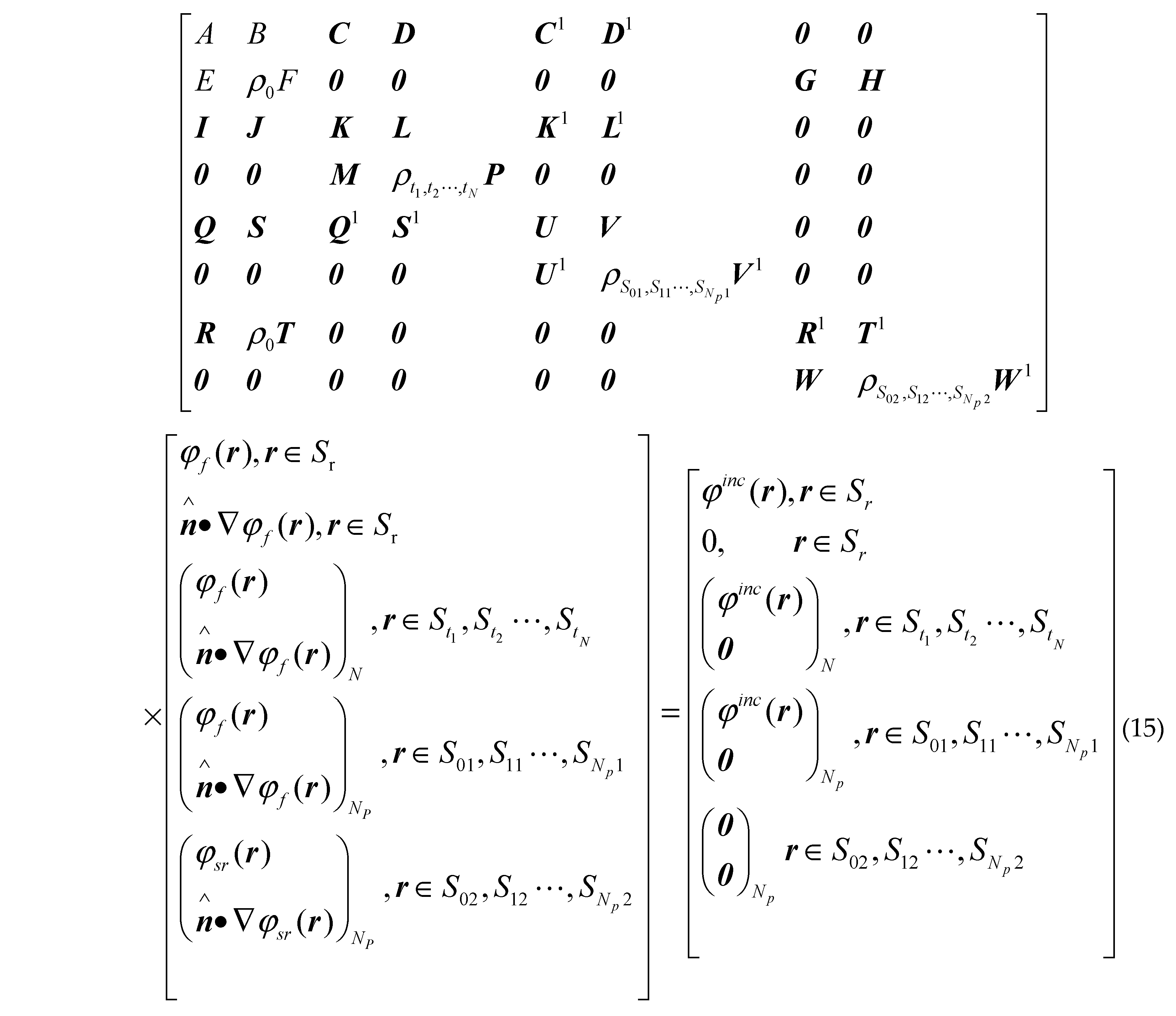
Discrete the sea contour S r along the direction of x ,and N class missile targets, N p class ship targets along their surface contours using regular pulse function and point matching test, the following matrix can be obtained: Preprints 85457 i007 where ( φ f ( r ) n φ f ( r ) ) N , r S t 1 , S t 2 , S t N denotes
[ ( φ f ( r ) n φ f ( r ) ) | r S t 1 , ( φ f ( r ) n φ f ( r ) ) | r S t 2 ( φ f ( r ) n φ f ( r ) ) | r S t N ]
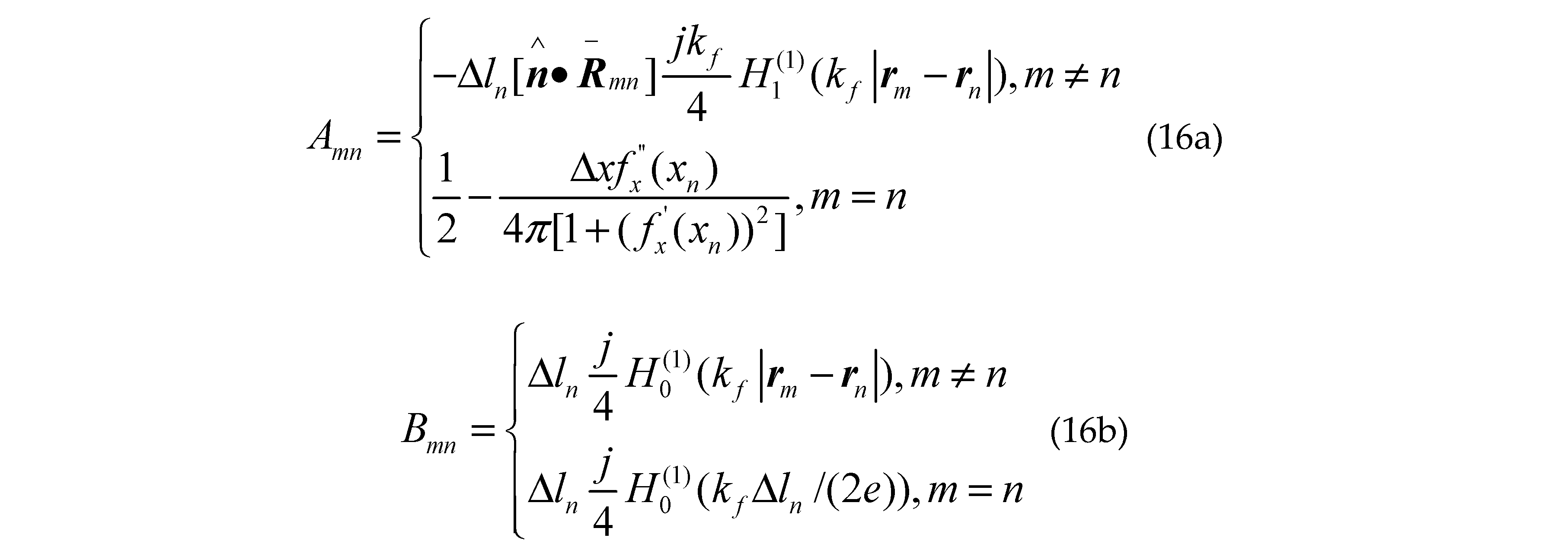
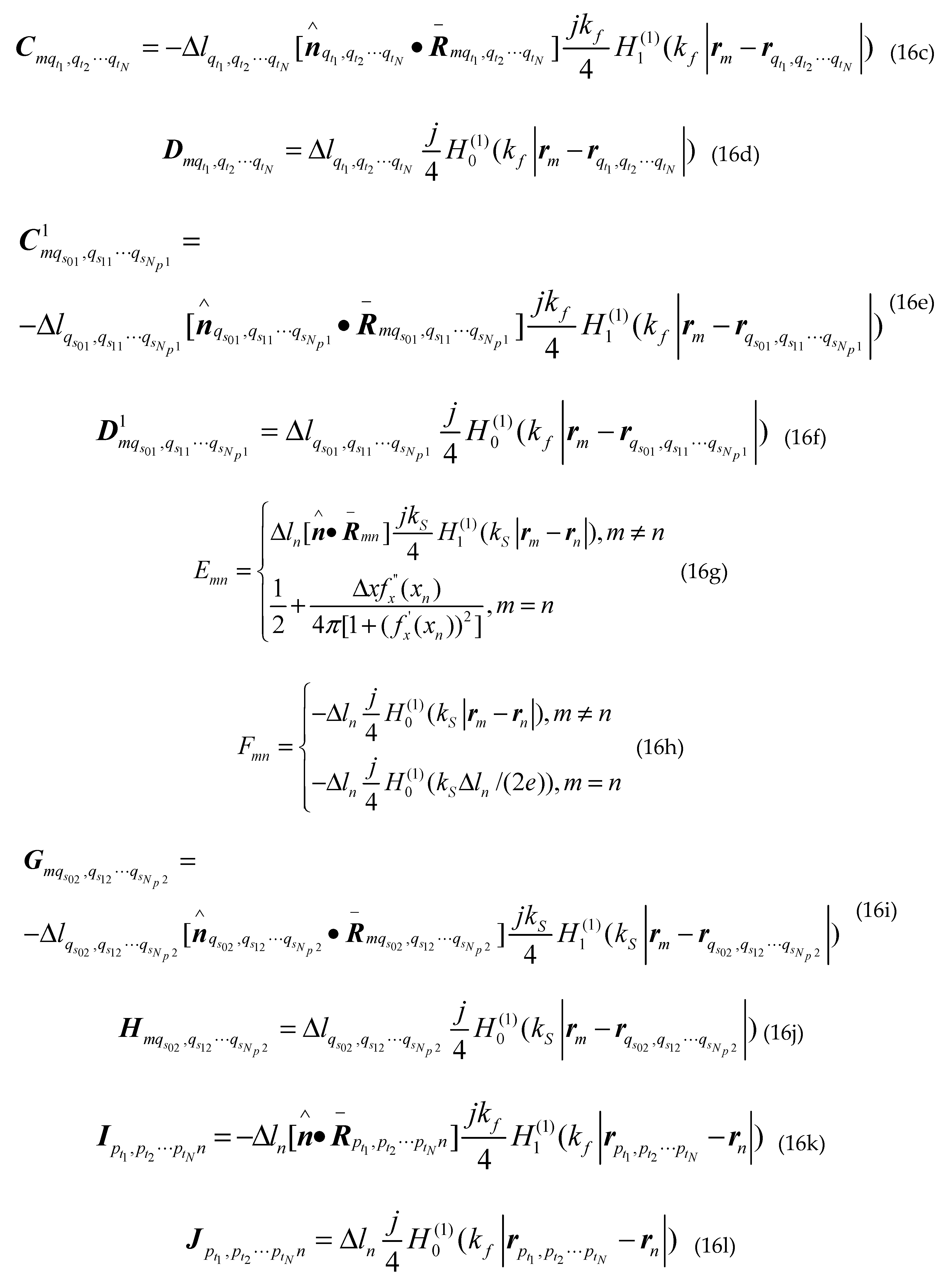
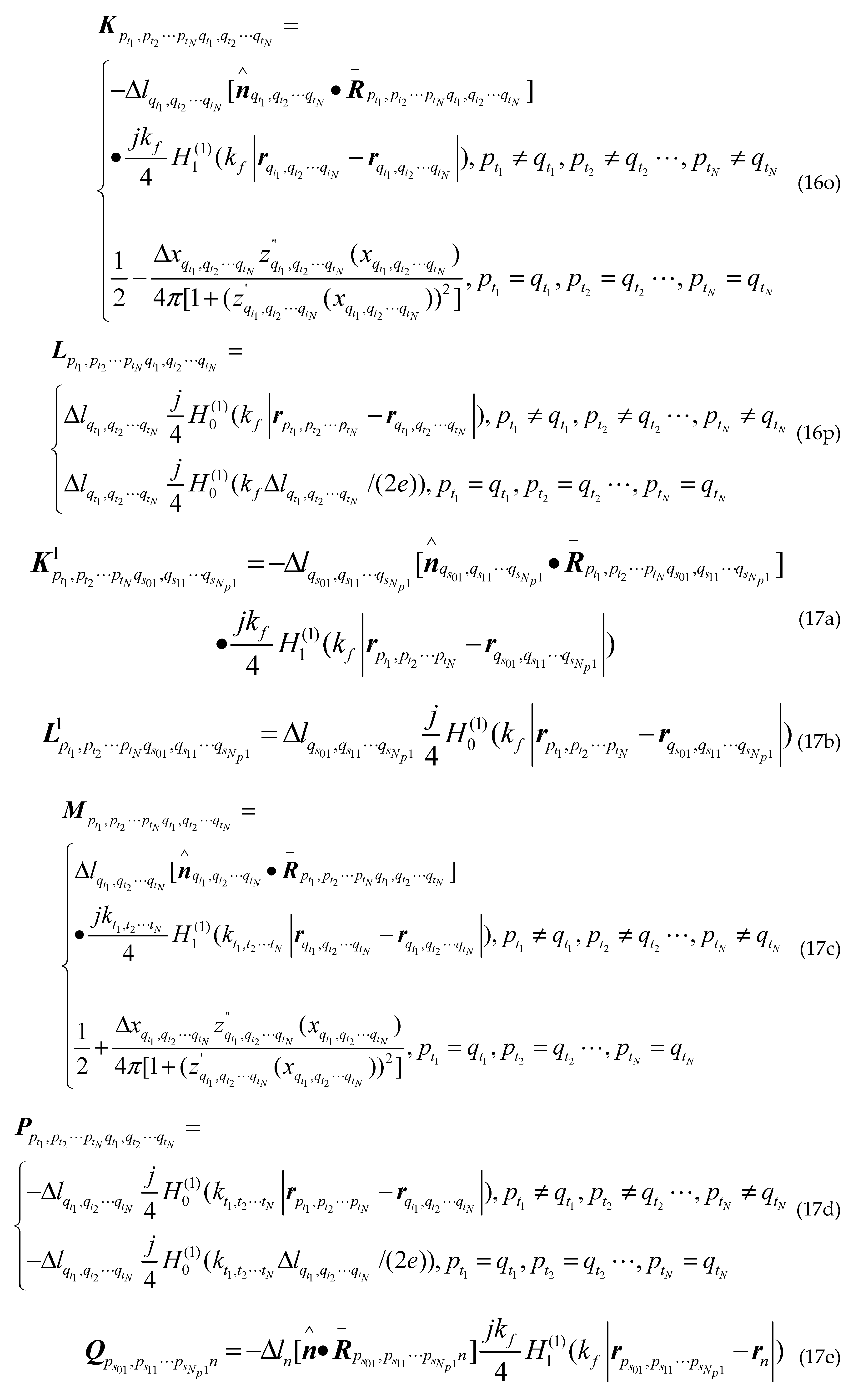
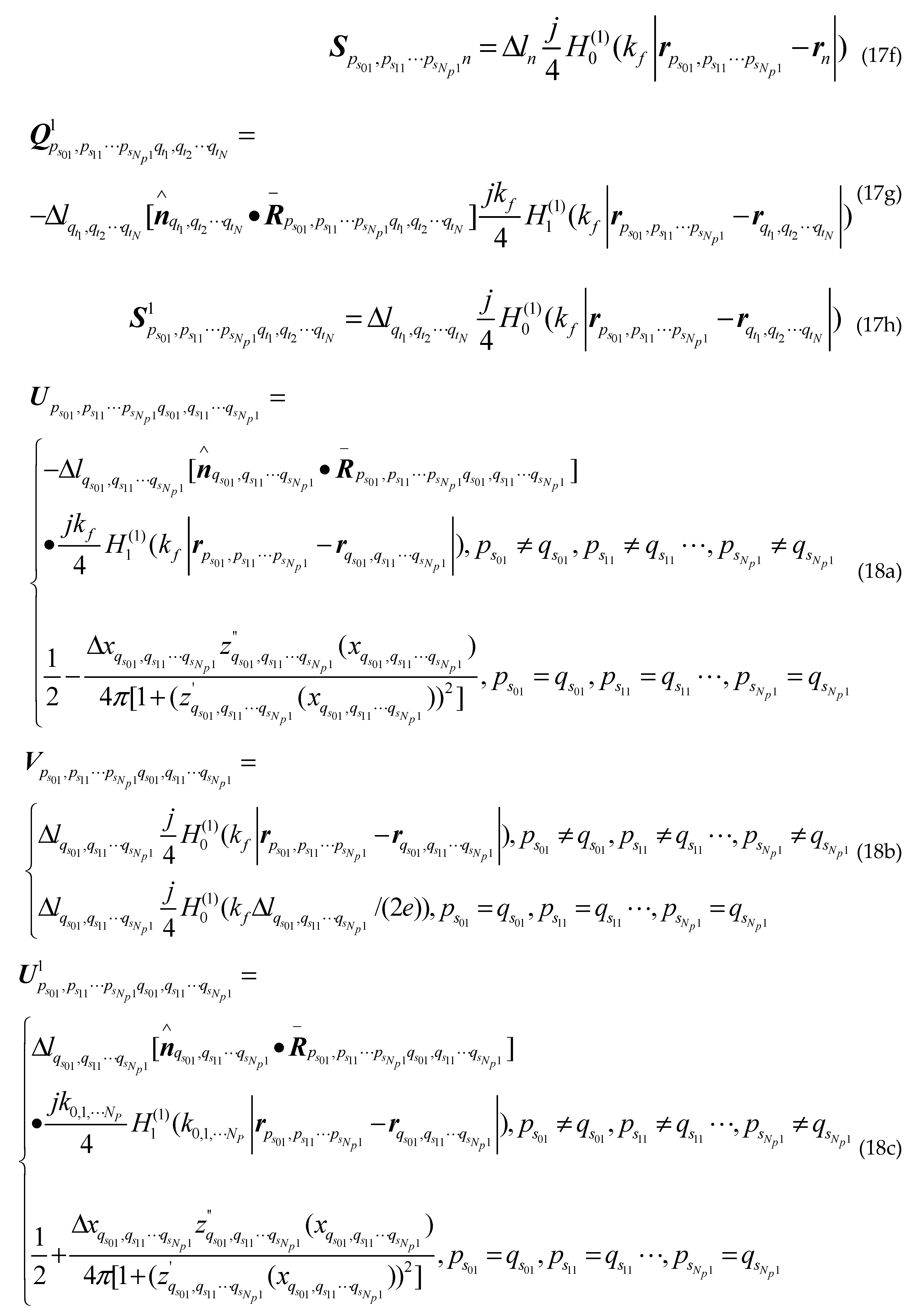
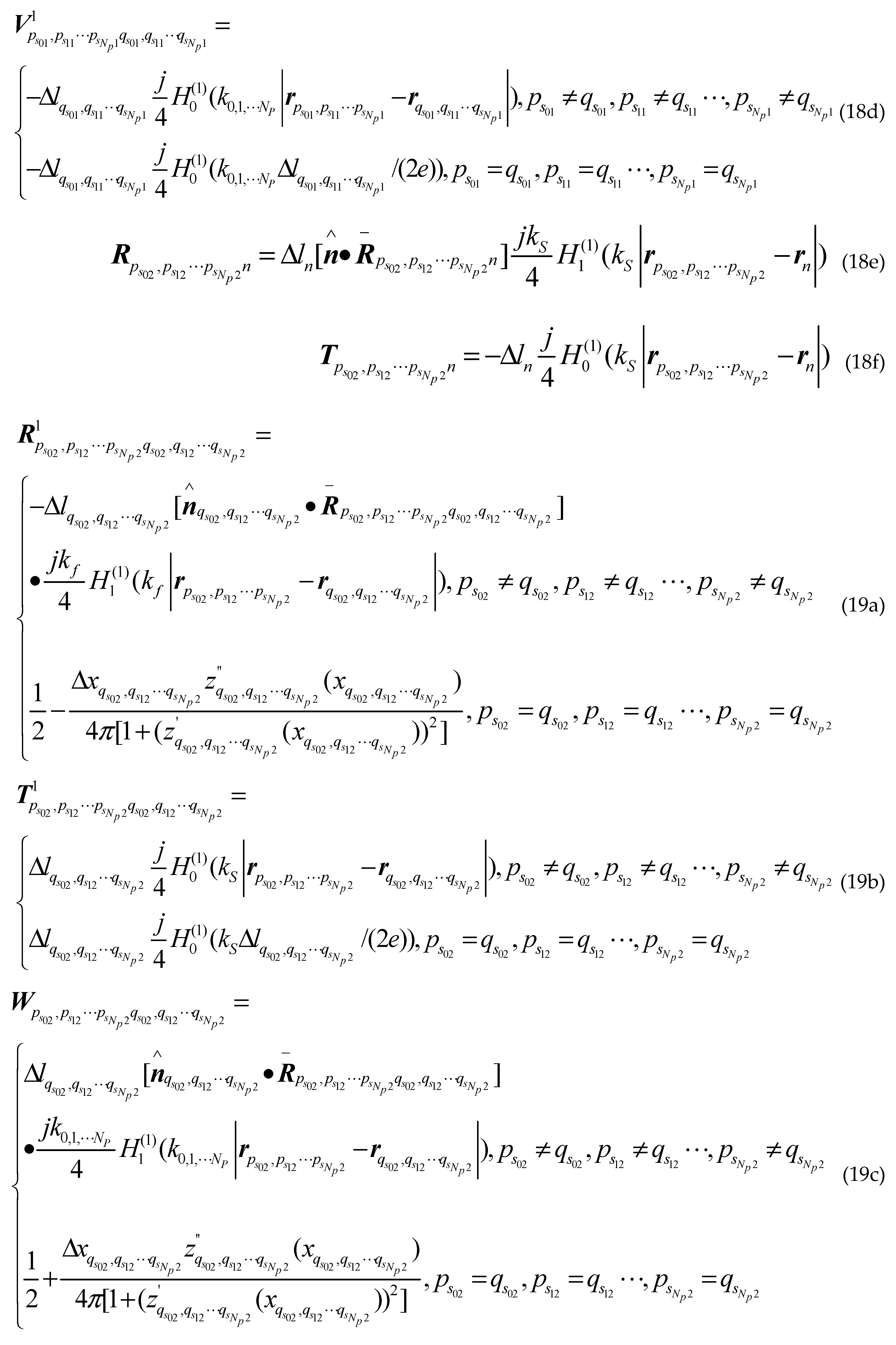
thus each element of the impedance matrix is expressed as: Preprints 85457 i008Preprints 85457 i009Preprints 85457 i010Preprints 85457 i011Preprints 85457 i012Preprints 85457 i013 Where H 1 ( 1 ) is the first kind first order Hankel function; f x ' ' ( x ) is the second derivative of the sea surface function f ( x ) ; z q t 1 , q t 2 q t N ' , z q s 01 , q s 11 q s N p 1 ' and z q s 02 , q s 12 q s N p 2 ' are the first derivative of the class missile target surface contours, the class ship target surface contours upper and lower the sea surface; z q t 1 , q t 2 q t N ' ' , z q s 01 , q s 11 q s N p 1 ' ' and z q s 02 , q s 12 q s N p 2 ' ' are the second derivative of the class missile target surface contours, the class ship target surface contours upper and lower the sea surface; r m , r n are arbitrary two points on sea surface S r ; r p t 1 , p t 2 p t N , r q t 1 , q t 2 q t N are arbitrary two points on different class missile target surfaces; r p s 01 , p s 11 p s N p 1 , r q s 01 , q s 11 q s N p 1 are arbitrary two points on upper surface of different class ship targets; r p s 02 , p s 12 p s N p 2 , r q s 02 , q s 12 q s N p 2 are arbitrary two points on lower surface of different class ship targets; other groups are as follows: Preprints 85457 i013
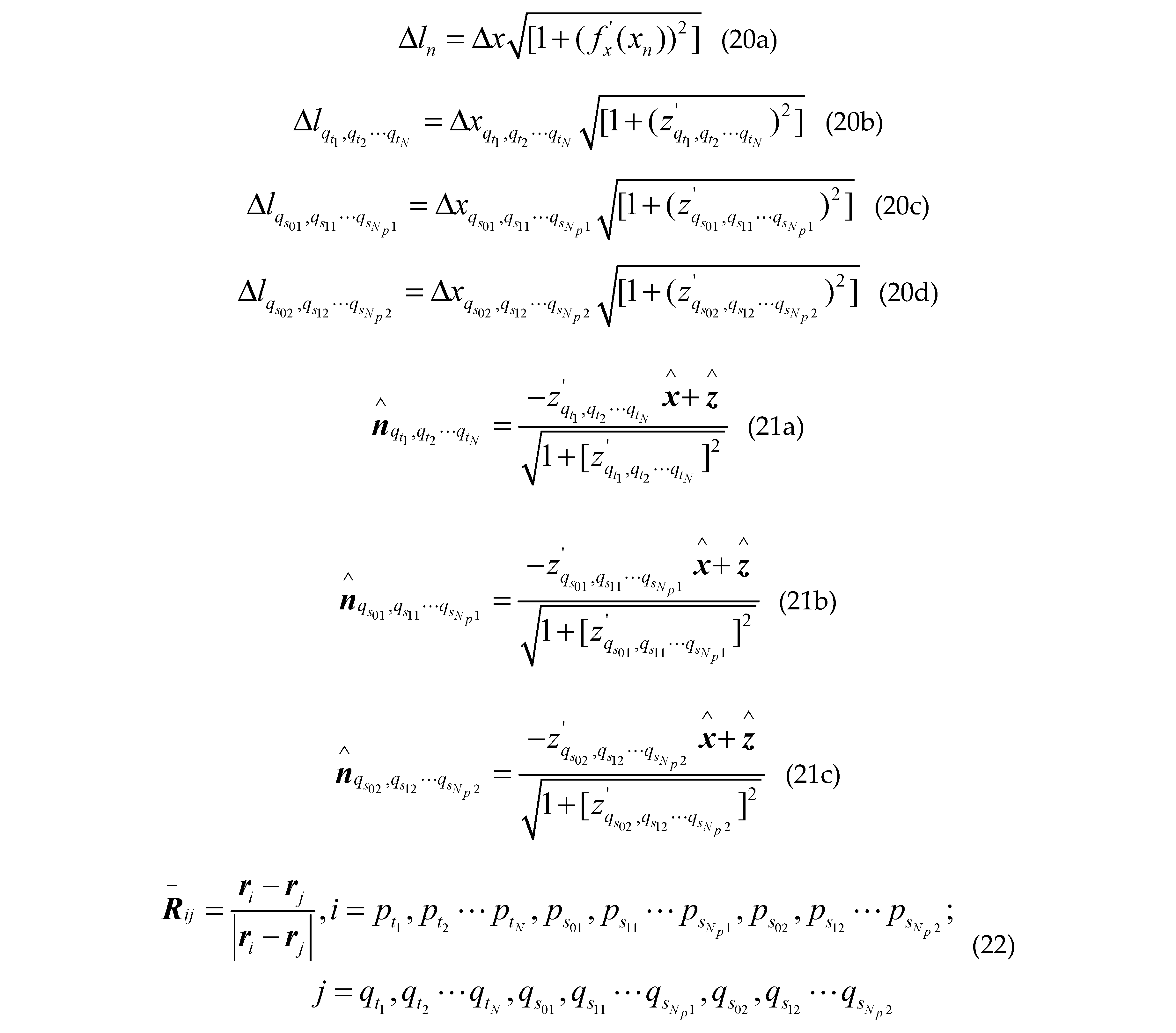
Using far-field approximation ( | r | ), the two-dimensional Green function can be approximated as [26]: Preprints 85457 i014
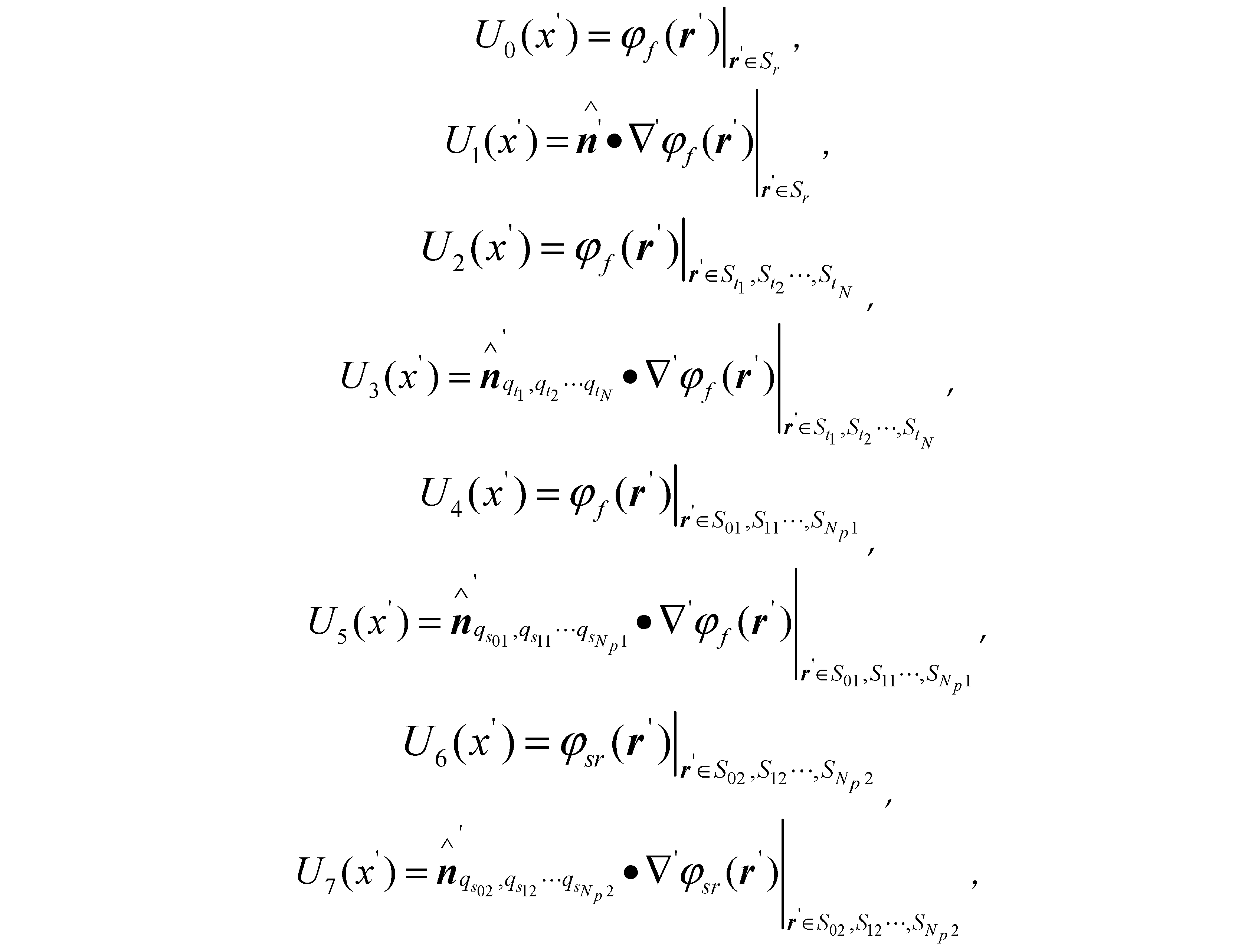
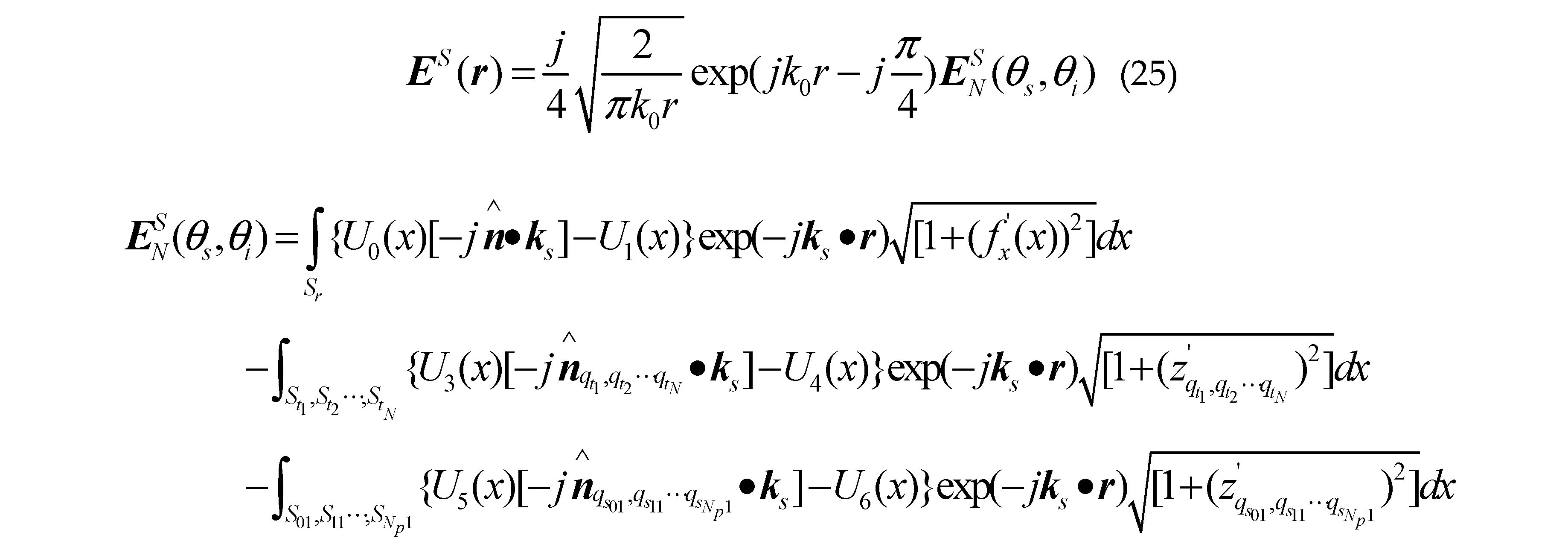
Let Preprints 85457 i015 So the scattered field at any point in Ω 0 space can be obtained: Preprints 85457 i016 where k i = k 0 ( x sin θ i cos ϑ i z cos θ i ) , k s = k 0 ( x sin θ s cos ϑ s + z cos θ s ) , r ' = x x ' + z z ' , θ i is the incident angle, θ s is the scattering angle, ϑ i is the incident azimuth, ϑ s is the scattering azimuth.
Here, we use the tapered wave incidence, which gives: Preprints 85457 i017 Where g z is the tapered wave width factor, W ( r ) = 2 ( x + z tan θ i ) 2 / g z 1 ( k 0 g z cos θ i ) 2
According to the definition of electromagnetic scattering coefficient [27], then the composite scattering coefficient can be computed: Preprints 85457 i018

2.3. Establish the coordinates for targets above the sea

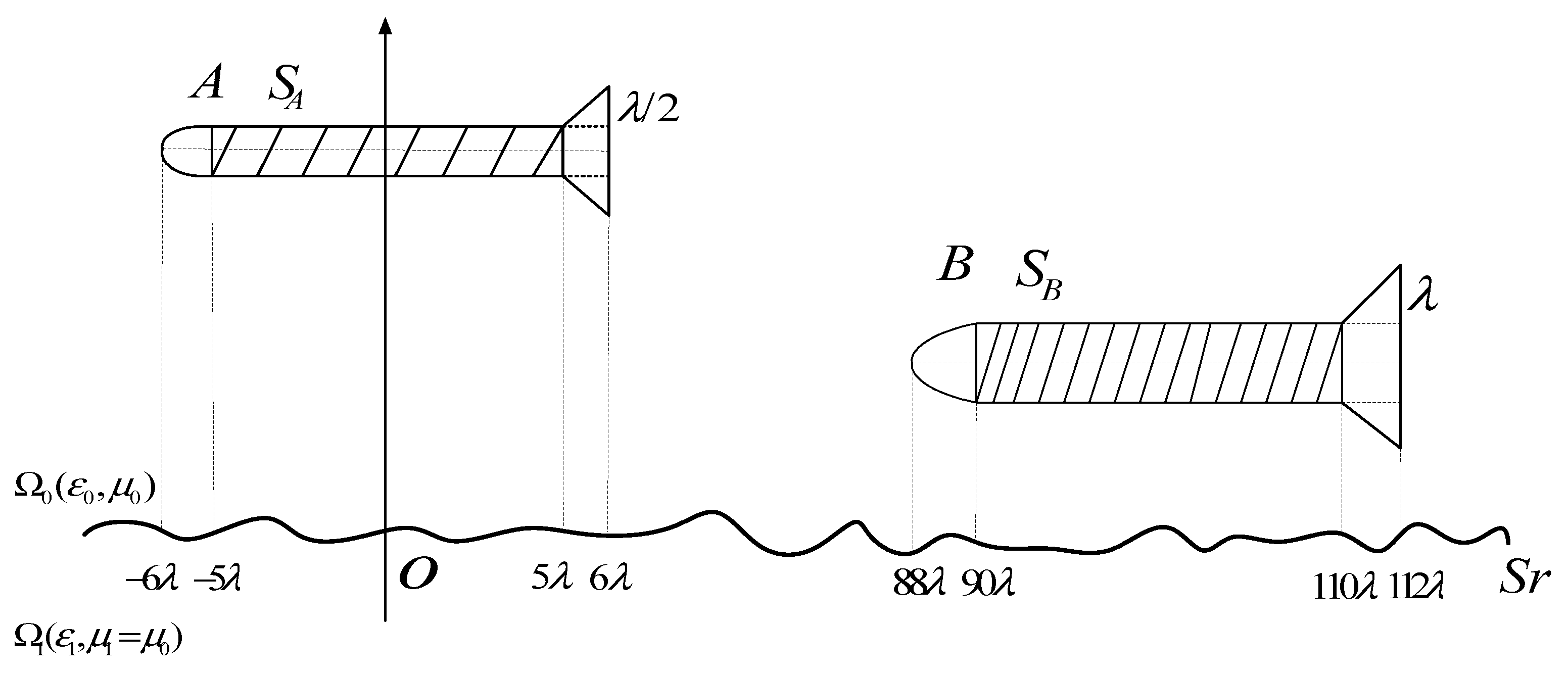
Here is coordinate diagram for two dielectric targets above one-dimensional fractal sea surface shown in Figure 2, assuming that the geometric center coordinates of the class missile target A is A ( 0 , H A ) , and the geometric center coordinates of the class ship target B is B ( X B , H B ) , thus the coordinate formula of the target A is:
When 6 λ x A 5 λ ,
( x A + 5 λ ) 2 + ( z A H A ) 2 = ( λ ) 2
When 5 λ < x A 5 λ ,
| z A H A | = 10 λ
When 5 λ < x A 6 λ ,
| z A H A | = 1 2 ( x A 5 λ ) + λ
While the coordinate formula of the target B is:
When 88 λ x A 90 λ ,
( x B 90 λ ) 2 + ( z B H B ) 2 = ( 2 λ ) 2
When 90 λ < x B 110 λ ,
| z B H B | = 2 λ
When 110 λ < x B 112 λ ,
| z B H B | = 1 2 ( x B 110 λ ) + 2 λ

3. Numerical examples

3.1. Effect of class missile target permittivity and spatial locations on composite scattering coefficient

Firstly, the effect of different target permittivity on bistatic composite scattering coefficient is studied when a class missile target is above a sea surface. Here, we use the tapered wave, and the tapered wave width factor meets the requirements of wave dynamic equation, related length and energy truncation. Radar and two-dimensional fractal sea surface model parameters is shown in Table 1.
The coordinates of the class missile target are shown in Figure 2, the height of target A is 30m,the simulation results are shown in Figure 3 when the permittivity of target A is ε r t = 1 . 71 + j * 0 . 55 , 3 . 92 + j * 0 . 76 , 8 . 11 + j * 6 . 86 , respectively. From Figure 3, it can be seen that strong scattering wave occurred at the specular direction when the cone-shape wave illuminated the targets and the sea surface at the 30° incident angle. Within a small range of scattering angle, there is little effect of target permittivity on the composite scattering coefficient. However, for the large and middle range of scattering angle, the bistatic composite scattering coefficient increases with the dielectric of the targets increasing and this is due to the fact that the absorption loss of dielectric material decreases with the permittivity increasing.
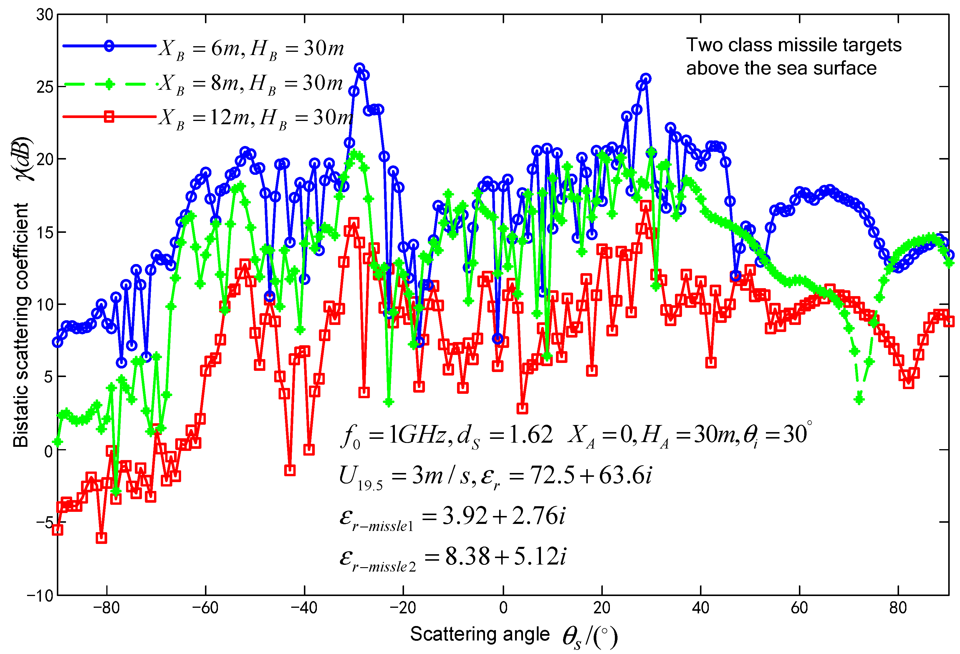
Consider two class missile targets A and B at different locations above the sea surface. When fixes the spatial location of target A and moves the target B towards target A, the composite scattering coefficient variation with scattering angle is discussed. Target A is located at the coordinate of (0,30m), the height of target B is H B = 30 m , the other parameters of targets and 1-D fractal sea surface are the same to the above. When the distance between A and B is 6m,8m,12m, respectively, the simulation results are shown in Figure 4. From Figure 4, it can be seen that, with the target moving close to the center of illumination, the composite scattering coefficient overally increases and this is resulted from the non-uniformity of the cone-shape incident wave. Closer to the center of the illuminated sea surface, the incident power is more larger. This made the induction of the targets and the interaction between the sea surface and the targets increase. Oppositely, far away from the center of the illuminated sea surface, the incident wave becomes weak, which makes the induced fields on target surface and the interaction between sea surface and the target decrease. The backscattered peak near 30° results from the intensive reflection of the target. The amplitude of the peak increases with the wavelength of incident wave increasing.

3.2. Impact of Seawater permittivity, fractal dimensions, wind speed at sea surface on composite scattering coefficient

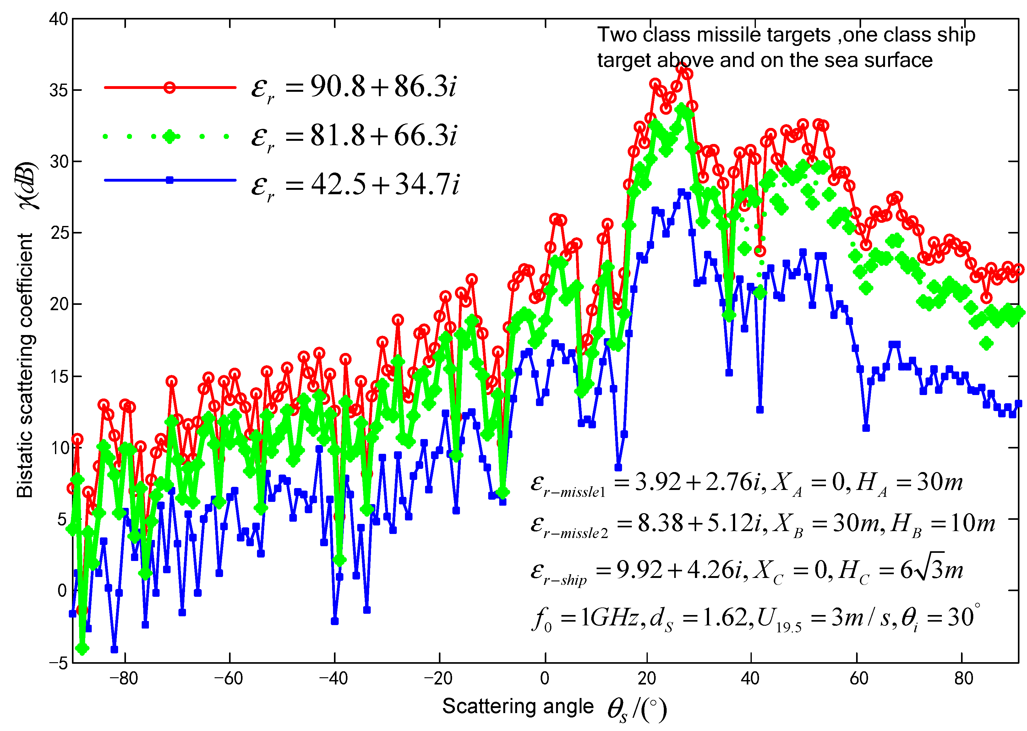
For the scene of the sea surface with two class missile targets and one class ship dielectric target above it, the effect of seawater permittivity on composite coefficient is studied. The size of the class ship target is shown in Figure 1 and the size of the class missile target is shown in Figure 2, respectively. Target A is located at (0m, 30m) above the sea surface. Target B is located at (30m, 10m) above the sea surface. The class ship target C with permittivity of ε r s h i p = 9 . 92 + j * 4 . 26 is at a draught of 6 3 m. The permittivity of seawater is chosen as ε r = 90 . 8 + j * 83 . 3 , 81 . 8 + j * 66 . 3 , 42 . 5 + j * 34 . 7 , as shown in Figure 5. From Figure 5, it can be seen that the effects of different seawater permittivity on forward scattering and backward scattering are different. In the domain of forward scattering, the scattering coefficient decreases with the seawater permittivity increasing; whereas in the backscattering domain, scattering coefficient is nearly a constant. This is due to the fact that in the forward scattering and backward scattering domains the absorption losses of the dielectric are different.
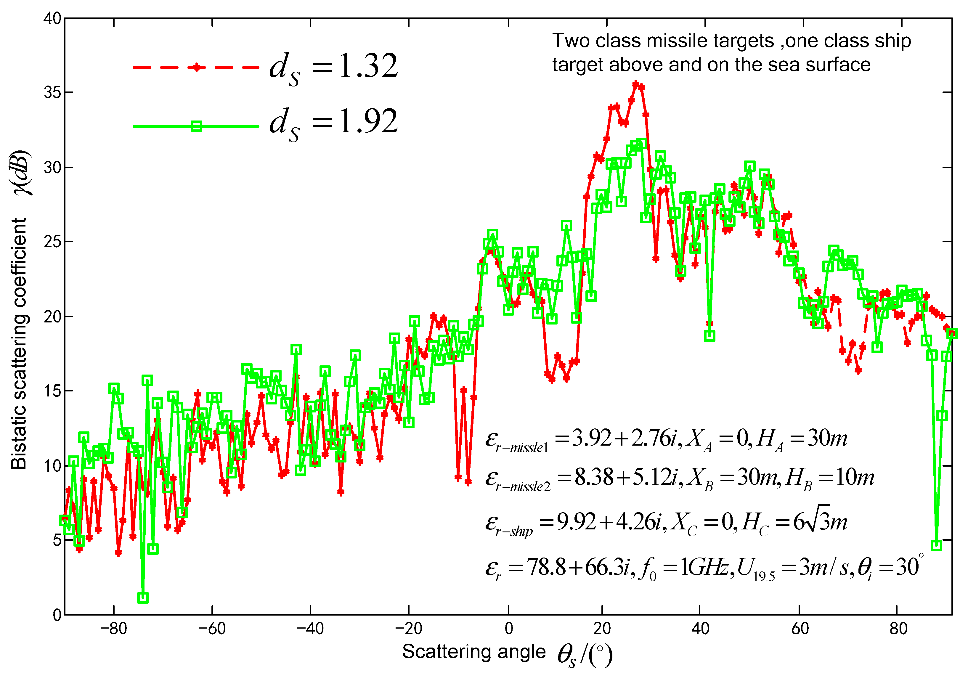
For the scene of sea surface with two class missile targets and one class ship dielectric target above it, the effect of the sea surface fractal dimension on composite coefficient is studied. It is assumed that the relative permittivity of seawater is ε r = 78 . 8 + j * 66 . 3 , parameters of the fractal sea surface and the location of target A, target B, target C are the same as above. The fractal dimension of the sea surface is d S = 1 . 32 , 1 . 92 , respectively. The simulation results are shown in Figure 6. From Figure 6, it can be seen that, at the incoherent scattering angles, if the fractal dimension is larger, the scattering coefficient is larger as well; whereas the composite coefficient decreases with the fractal dimension increasing at the spectacle direction. This is because there is a linear relationship between the fractal dimension of 1-D sea surface and its correlation length. For example, when d S = 1 . 22 , 1 . 32 , 1 . 62 , 1 . 92 , there is l x = 0 . 5544 , 0 . 5515 , 0 . 5398 , 0 . 5295 . The correlation length decreases when the fractal dimension increases, and the sea surface root-mean-square slope increases if the roughness of sea surface is given. This results in the energy in the incoherent scattering domain increasing and the energy in the coherent scattering domain decreasing.
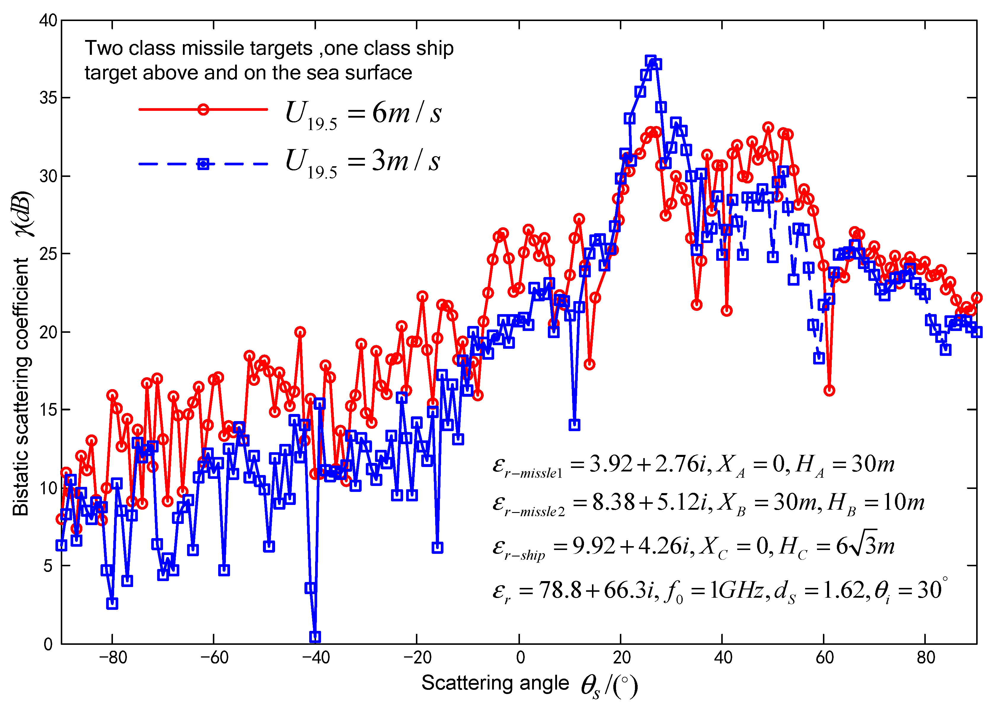
For the scene of sea surface with two class missile targets and one class ship dielectric target above it, the effect of wind speed at sea surface on composite coefficient is studied. It is assumed that the relative permittivity of seawater is ε r = 78 . 8 + j * 66 . 3 , the fractal dimension of the sea surface is d S = 1 . 62 , and the location of targets A, targets B, targets C are the same as above. The wind speeds are respectively 3m/s and 6m/s, the simulation is shown in Figure 7. From Figure 7, it can be seen that the composite scattering in the non-spectacle domain increases with the wind speed increasing. The reason is that the incoherent scattering coefficient increases with the wind speed and the interaction between the sea surface and the targets increasing. Furthermore, at the direction of spectacle scattering, when the wind speed is small, the roughness of the sea surface decreases, which results in the increasing coherent scattering. Therefore, the composite coefficient is large. Oppositely, when the wind speed increases, the sea surface becomes rough, and the coherent scattering becomes weak. These result in the peak in the spectacle direction decreasing.

4. Conclusions

For the composite scattering problem on the rough sea surface and multiple dielectric targets on and above it, an approach to solve the composite coefficient using method of moment is proposed. In the content above, multiple class missile targets above and multiple class ships floating on the dielectric sea surface are considered into a complex electromagnetic scattering scene. A set of integral equations is built and the impedance matrix is deduced. One type of missile, two missiles, two missiles and a ship on the sea are respectively selected and discuss are carried out. Parameters of the sea surface, such as fractal dimension, wind speed, seawater and target dielectric, and location of targets are referred. Their effects on composite scattering coefficient are studied. From the simulation results, it can be seen that the missile’s dielectric characteristics, spatial position and wind speed are sensitive to the effect of the composite scattering coefficient. This approach can be used to solve several problems, such as targets above dielectric or metal rough surface, ship targets floating on dielectric or metal rough surface. It can be generalized and expanded at a certain degree. Furthermore, it needs to point out this article does not discusses the scenes of multiple targets on the sea or multiple ship targets on the sea surface and the real sea surface and targets both are two dimensional, the application of this approach to 2-D sea surface electromagnetic scattering needs to be studied further.

Author Contributions

Conceptualization, writing-review and editing, visualization; Conceptualization, formal analysis, writing-review and editing. All authors have read and agreed to the published version of the manuscript.

Funding

This work was supported in part by the special H-2018 for the development equipment of naval (No.H-2018) and the school fund C2020-018(No.C2020-018).

Data Availability Statement

Not applicable.

Acknowledgments

The authors are grateful to the responsible Editor and the anonymous reviewers for their valuable comments and suggestions, which have greatly improved this paper.

Conflicts of Interest

The authors declare no conflict of interest.

References

  1. Niu, B.; Gu, L.; Gong, C. Measure the performance of cooperative detection of sea-skimming target. 2012 11th International Conference on Signal Processing (ICSP 2012). LOCATION OF CONFERENCE, ChinaDATE OF CONFERENCE; pp. 2262–2265. [CrossRef]
  2. Gini. F, Greco. M, “A suboptimum approach to adaptive coherent radar detection in compound- Gaussian clutter,” IEEE Trans on Aerospace and Electronic Systems. 35(3), 1095-1104(1999). [CrossRef]
  3. Conte. E Lops. M, “Asymptotically optimum radar detection in compound-Gaussian clutter,” IEEE Trans on Aerospace and Electronic Systems. 31(2), 617-625(1995). [CrossRef]
  4. Winebrenner, D.P.; Ishimaru, A. Application of the phase-perturbation technique to randomly rough surfaces. J. Opt. Soc. Am. A 1985, 2, 2285–2293. [Google Scholar] [CrossRef]
  5. Holliday, D. Resolution of a controversy surrounding the Kirchhoff approach and the small perturbation method in rough surface scattering theory. IEEE Trans. Antennas Propag. 1987, 35, 120–122. [Google Scholar] [CrossRef]
  6. Tian, G.; Tong, C.; Sun, H.; Zou, G.; Liu, H. Improved Hybrid Algorithm for Composite Scattering From Multiple 3D Objects Above a 2D Random Dielectric Rough Surface. IEEE Access 2020, 9, 4435–4446. [Google Scholar] [CrossRef]
  7. Tian, J.; Tong, J.; Shi, J.; Gui, L. A new approximate fast method of computing the scattering from multilayer rough surfaces based on the Kirchhoff approximation. Radio Sci. 2017, 52, 186–195. [Google Scholar] [CrossRef]
  8. Pinel, N.; Le Bastard, C.; Bourlier, C. Modeling of EM Wave Coherent Scattering From a Rough Multilayered Medium With the Scalar Kirchhoff Approximation for GPR Applications. IEEE Trans. Geosci. Remote. Sens. 2019, 58, 1654–1664. [Google Scholar] [CrossRef]
  9. Hira Lynn Broschat, “The phase perturbation approximation for rough surface scattering from a pierson-moskowitz sea surface”. IEEE Trans on Geoscience and Remote Sensing, 1993, 31(1): 278-279. [CrossRef]
  10. Afifi, S.; Dusseaux, R. Scattering From 2-D Perfect Electromagnetic Conductor Rough Surface: Analysis With the Small Perturbation Method and the Small-Slope Approximation. IEEE Trans. Antennas Propag. 2017, 66, 340–346. [Google Scholar] [CrossRef]
  11. Xu Xiaoyan, “The Forward-Backward IPO algorithm for Calculating Open-Ended Cavities,” Space Electronic Technology.(1), 72-75(2008).
  12. J. Ma, L. X. J. Ma, L. X. Guo and H. Zeng, “The FIT-MoM Hybrid Method for Analysis of Electromagnetic Scattering by Dielectric Bodies of Revolution” IEEE Transactions on Antennas and Propagation. 66(3), 1384-1388(2018). [CrossRef]
  13. Ozgun, O.; Kuzuoglu, M. A Domain Decomposition Finite-Element Method for Modeling Electromagnetic Scattering From Rough Sea Surfaces With Emphasis on Near-Forward Scattering. IEEE Trans. Antennas Propag. 2018, 67, 335–345. [Google Scholar] [CrossRef]
  14. Smith, D.R.; Burns, S.; Simpson, J.J.; Ferrone, S.M. FDTD Modeling of Scattered Ultra-Low Frequency Electromagnetic Waves From Objects Submerged in the Ocean. IEEE Trans. Antennas Propag. 2019, 67, 2534–2541. [Google Scholar] [CrossRef]
  15. Iodice, A. Forward-backward method for scattering from dielectric rough surfaces. 50. [CrossRef]
  16. Liang, Y.; Guo, L.; Wu, Z. The EPILE Combined With the Generalized-FBM for Analyzing the Scattering From Targets Above and on a Rough Surface. IEEE Antennas Wirel. Propag. Lett. 2010, 9, 809–813. [Google Scholar] [CrossRef]
  17. Li, Z.; Jin, Y.-Q. Bistatic scattering from a fractal dynamic rough sea surface with a ship presence at low grazing-angle incidence using the GFBM/SAA. Microw. Opt. Technol. Lett. 2001, 31, 146–151. [Google Scholar] [CrossRef]
  18. G. Kubicke, C. G. Kubicke, C. Bourlier, and J. Saillard. Scattering by an object above a randomly rough surface from a fast numerical method: Extended PILE method combined with FB-SA [J].Waves in Random and Complex Media. 2008, 18(3):495-519. [CrossRef]
  19. X.Ye, Y-Q.Jin. Fast iterative approach to difference scattering from the target above a rough surface [J]. IEEE Trans on Geoscience and Remote Sensing, 2006, 44(l):108-115. [CrossRef]
  20. H.X.YOU,” A hybrid KA-MOM algorithm for computation of scattering from a 3D PEC target above a dielectric rough surface,” Radio Sci. 43 (3), 3008-3018(2008). [CrossRef]
  21. Pham-Xuan, V.; Trinh, D.; De Gersem, H.; Brennan, C. Novel Iterative Algorithm for the Solution of Electromagnetic Scattering From Layered Random Rough Surfaces. IEEE Trans. Antennas Propag. 2018, 66, 3810–3815. [Google Scholar] [CrossRef]
  22. Zhang, M.; Zhao, Y.; Li, J.-X.; Wei, P.-B. Reliable Approach for Composite Scattering Calculation From Ship Over a Sea Surface Based on FBAM and GO-PO Models. 65. [CrossRef]
  23. Wang Yunhua,Guo Lixin,Wu Zhensen,” The application of an improved 2D fractal model for electromagnetic scattering from the sea surface,” Acta Physica Sinica, 55(10), 5193-5195(2006).
  24. F. Berizzi, D. M. F. Berizzi, D. M. Enzo, “Fractal analysis of the signal scattered from the sea surface,” IEEE Trans on Antennas and Propagation. 47(2), 325-327(1999). [CrossRef]
  25. Shay, N.R.; Weile, D.S.; Kastner, R. Balanced Electric-Magnetic Absorber Green’s Function Method for MoM Matrix Thinning and Conditioning. IEEE Trans. Antennas Propag. 2018, 66, 2996–3001. [Google Scholar] [CrossRef]
  26. B. Guan, J. F. B. Guan, J. F. Zhang, “Electromagnetic scattering from objects above a rough surface using the method of moments with half-space Green’s function,“ IEEE Trans on Geoscience and Remote Sensing, 47(10), 3399-3405(2009. [CrossRef]
  27. Guérin, C.-A.; Soriano, G.; Chapron, B. The weighted curvature approximation in scattering from sea surfaces. Waves Random Complex Media 2010, 20, 364–384. [Google Scholar] [CrossRef]
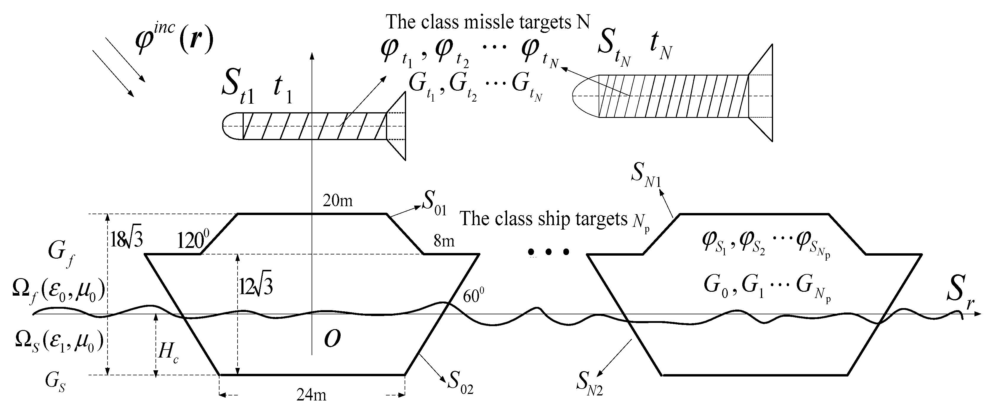
Figure 1. Scattering diagram of multiple dielectric targets above and on one-dimensional fractal sea surface.
Preprints 85457 g001
Figure 2. Coordinates diagram for two dielectric targets above one-dimensional fractal sea surface.
Preprints 85457 g002
Figure 3. Bistatic scattering coefficient variations with scattering angle for different permittivity of class missile targets.
Preprints 85457 g003
Figure 4. Bistatic scattering coefficient variations with scattering angle for different locations of class missile targets.
Preprints 85457 g004
Figure 5. Bistatic scattering coefficient variations with scattering angle at different permittivity of sea surface.
Preprints 85457 g005
Figure 6. Bistatic scattering coefficient variation with scattering angle at different fractal dimensions of sea surface.
Preprints 85457 g006
Figure 7. Bistatic scattering coefficient variation with scattering angle at different wind speeds at sea surface.
Preprints 85457 g007
Table 1. Radar and two-dimensional fractal sea surface model parameters.
Parameter items Simulation value
Incident angle of the tapered wave θ i 30°
Incident frequency f 0 1 G H z
The wind speed at 19.5 m above the sea surface U 19.5 3m/s
Observation time t 0.25s
Observation distance L f 90m
Sample frequency f r 6kHz
Gravity constant g 9.8
Power-law factor ξ 2.9
Correction factor ς 1.65
Fractal dimension d s 1.62
Scale factor a 0.985
Scale factor b 1.015
Number of resonant waves N 1 400
Normalization constant η 0.152
Relative Speed of target to sea surface V x 360m/s
Relative dielectric of the sea water ε r 72.5+j63.6
Angular propagation direction β 1 m , β 2 n 45°
Fundamental wavenumber k 0 0.84
Standard deviation of the amplitude σ 0.19
Disclaimer/Publisher’s Note: The statements, opinions and data contained in all publications are solely those of the individual author(s) and contributor(s) and not of MDPI and/or the editor(s). MDPI and/or the editor(s) disclaim responsibility for any injury to people or property resulting from any ideas, methods, instructions or products referred to in the content.
Copyright: This open access article is published under a Creative Commons CC BY 4.0 license, which permit the free download, distribution, and reuse, provided that the author and preprint are cited in any reuse.
Prerpints.org logo

Preprints.org is a free preprint server supported by MDPI in Basel, Switzerland.

Subscribe

© 2024 MDPI (Basel, Switzerland) unless otherwise stated