1. Introduction
High-strength low-alloyed steels (HSLA) are well-known materials with a very good ratio between high yield as well as ultimate strength and low cost. These materials are frequently used in the automotive, petrochemical, and civil industries for heavily-loaded parts [
1,
2]. Their application also enables the reduction of construction weight for improved corrosion resistance [
3]. The low content of alloying elements with respect to their hardening is compensated by the thermo-mechanical treatment and small addition of Nb, Ti, and/or V. The sheets of HSLA are usually rolled at elevated temperatures (above the austenitisation temperature) followed by rapid cooling. The final strength of HSLA is a function of hot rolling conditions and the superimposing rate of consecutive cooling [
2,
3,
4,
5]. Furthermore, Nb, Ti, and V can play a certain role in microstructure refinement, their precipitates, and dissolution in the matrix [
3,
5,
6,
7]. The microstructure of thermo-mechanically treated low-alloyed steels of lower strength is mostly composed of refined ferrite as soon as the refined ferrite matrix becomes a mixture of ferrite + bainite or bainite + martensite. However, increasing strength comes at the expense of reduced toughness [
1,
8] and residual stresses are also altered [
8].
Components and structures made of HSLA are very often vital of importance with respect to system reliability and their long-term use. Their functionality is a function of initial state, design, load manner, etc. Their non-destructive monitoring in different applications is essential.
Magnetic Barkhausen noise (MBN) is obtained during magnetisation of the ferromagnetic bodies in the altered magnetic field. Domain walls (DWs) and pinned in their positions due to the presence of lattice imperfections, and their sudden motion in the form of irreversible jumps occurs when the external magnetic field reaches the pinning strength of the pinning sites [
9,
10]. Electromagnetic or acoustic pulses produced by these DWs during their irreversible motion can be detected on the free surface. MBN is sensitive to microstructure due to interference between DWs and all lattice imperfections, especially dislocation tangles [
11,
12], precipitates [
13,
14], grain boundaries [
15,
16], hard-ferromagnetic, or/and non-ferromagnetic phases [
17], etc. Furthermore, preferential crystallography and the corresponding magnetic alignment (anisotropy) affect the angular distribution of MBN [
18]. Finally, certain contributions of the stress state to MBN should be considered due to the positive magnetostriction and biaxial anisotropy of Fe alloys [
19,
20].
Consecutive bursts of MBN are usually very similar when the surface is magnetised through the hysteresis loop. Two consecutive bursts represent the ascending and descending routes of a magnetic field. However, these bursts can be different in some cases. During hard milling, such asymmetry can be found due to the magneto-coupling between the hard white layer and the underlying soft heat-affected zone [
21]. This effect was also observed in an amorphous bilayer ribbon (Fe73.5Nb3Si13.5B9Cu1/Fe74.5Nb3Si13.5B9) consisting of two layers of different magnetic hardness [
22]. Similar behaviour was reported with respect to plastic deformation under the uniaxial tensile test when this asymmetry is produced as a result of heterogeneity in dislocation density among the neighbouring grains and the associated differences in magnetic hardness of mutually-coupled grains [
23].
MBN is sensitive to alterations in the microstructure and stress state. For this reason, this study employed the MBN technique for the detection of surface state heterogeneity (made of HSLA 1100 MC). Apart from this aspect, the influence of the consecutive MBN bursts asymmetry and its influence on the MBN extracted feature are discussed. The components made of this HSLA could potentially be monitored by the MBN technique, and this study demonstrates the significance of the demagnetisation process for true and reliable MBN measurement. The origin of this asymmetry is not known, but its roots would be found somewhere during the manufacturing process.
2. Materials and Methods
The experiments were carried out on the HSLA 1100 MC (nominal yield strength 1100 MPa) received in the form of a sheet of length 3000 mm, width 1600 mm, and thickness 6 mm. The chemical composition of 1100 MC is indicated in
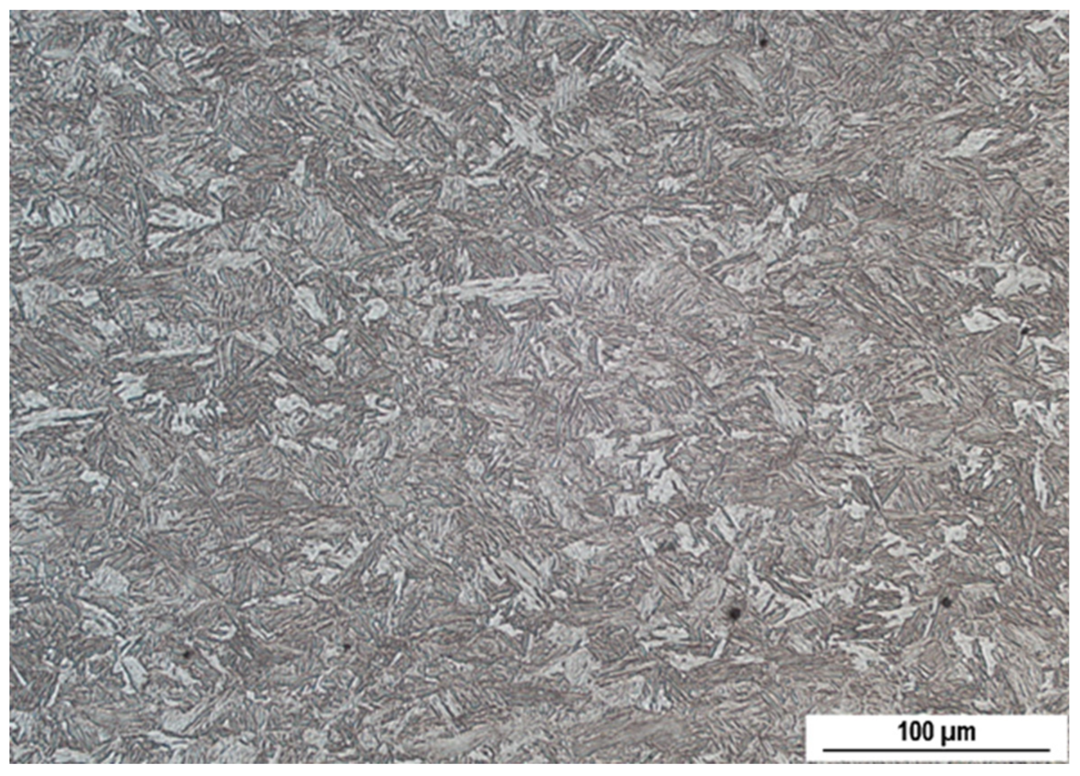
Table 1. The microstructure of this steel is composed of martensite with a small fraction of bainite. The exact conditions of hot rolling, as well as the cooling rate, are not known. The bulk microstructure of this steel is depicted in
Figure 1.
Preliminary screening of the received sheet revealed remarkably different MBN along the sheet width, whereas a much less pronounced heterogeneity was found along the sheet length. Additionally, a difference in the MBN with respect to the different sides of the sheet was also detected. The opposite sides of the sheet were marked as side A and side B. The MBN emission was measured along the width of the sheet in step 5 mm (318 measured points) in the center of the sheet with respect to its length. The excitation field was loaded along the rolling direction (RD), which corresponds to the length of the sheet. The transversal direction is abbreviated as TD. MBN measurements were carried out in the as-received state without any alteration of the surface and after demagnetisation as well.
Demagnetisation was performed using a Selos HD-2 demagnetising device in the vanishing magnetic field. The microstructure of the near-surface region was observed at two different positions exhibiting different MBN. Small specimens of length 20 mm were cut along RD, hot molded, ground, polished, and etched by 3% Nital for 5 seconds. Optical images were observed on the Neophot 2 microscope with Niss Elements software. Thermal softening of the near-surface region was checked by microhardness measurement HV0.1 using the Innova Test 400TM device (100g load per 10 seconds).
The MBN was measured in RD and TD by the RollScan 350 device coupled with the commercially available sensor S1-18-12-01. The device was controlled by MicroScan500 software MicroScan500 (altering the magnetic field ±4.6 kA.m-1 at frequency 125 Hz, detecting a range of MBN pulses from 10 to 1000 kHz). The MBN represents the rms (root mean square) value of the obtained MBN signal. MBN envelopes were constructed on the base of the filtered MBN signal and PP (Peak Position) as well as FWHM (Full Width at Half Maximum) of MBN envelopes were analyzed as well. PP is the magnetic field in which the maximum of the MBN envelope can be found. All extracted MBN features were obtained from 10 consecutive MBN bursts.
3. Results and discussion
3.1. Metallographic observations and microhardness measurements
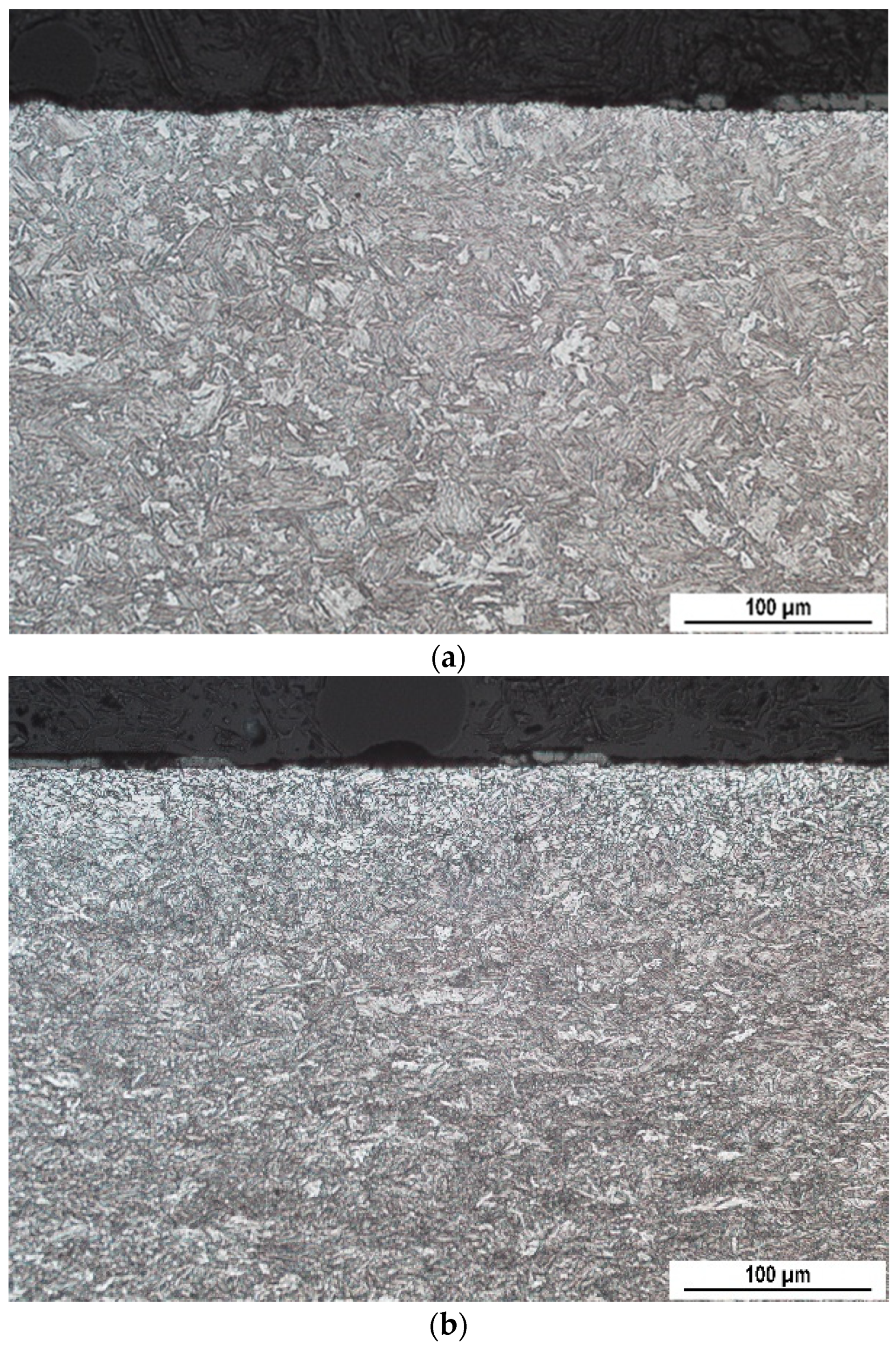
Figure 2 shows the metallographic images of the surface on side A in two different positions. These positions were chosen as the locations emitting the lowest (540 mV) and highest (1440 mV) MBN after demagnetisation.
Figure 2a shows that the near-surface is not fully composed of martensite, but the microstructure is gently altered in the thin layer below the free surface. These laths are mixed with fine ferrite equiaxed grains, which appear white on the metallographic image. This effect becomes more pronounced in
Figure 2b. This figure clearly demonstrates that the fine ferrite fully replaces the martensite in the near-surface region, and its extent is deeper toward the bulk compared to
Figure 2a.
Figure 2b also shows that the fine ferrite is also mixed with martensite (or bainite) in the deeper regions, and the fraction of fine ferrite decreases towards the bulk at the expense of lath martensite (or bainite).
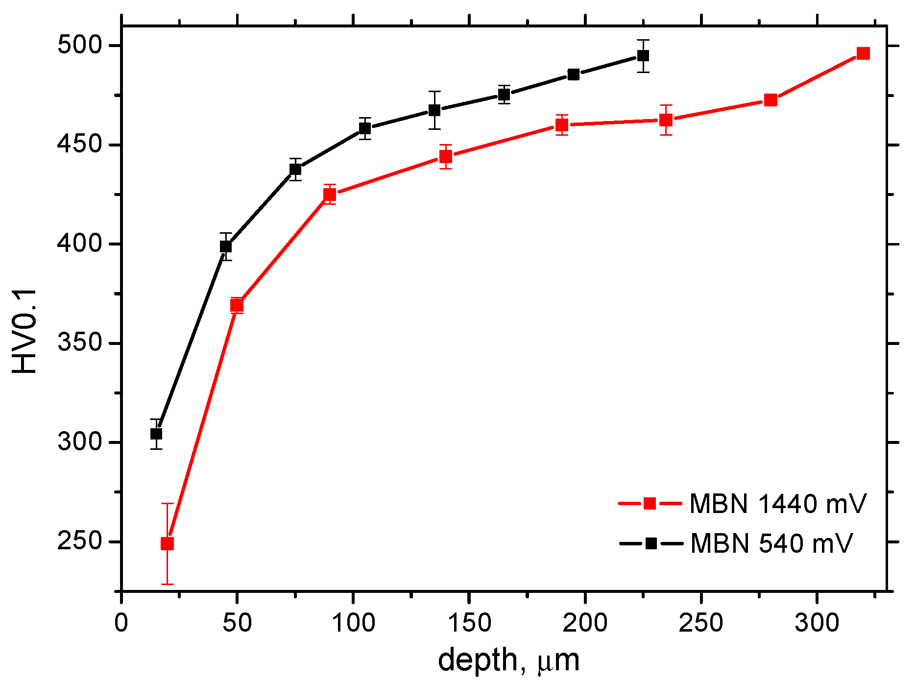
Figure 3 indicates that the near-surface region is softened in contrast to the deeper bulk. The degree and extent of this thermal softening are deeper for the region emitting higher MBN. Thermo-mechanically treated sheets made of 1100 MC are hot rolled at temperatures exceeding the austenitisation temperature. Performing such a process in the ambient atmosphere results in near-surface decarburising. The transformation of martensite requires very high cooling rates as well as a sufficient C content. The transformation of martensite is the shear process due to the over saturation of C in the Fe lattice [
24]. Decarburisation remarkably reduces C over saturation, which attenuates the shear process and results in a lower dislocation density. That is the reason why the decarburised surfaces suffer from softening. The decarburised layer usually appears white on metallographic images [
25,
26].
3.2. MBN measurements
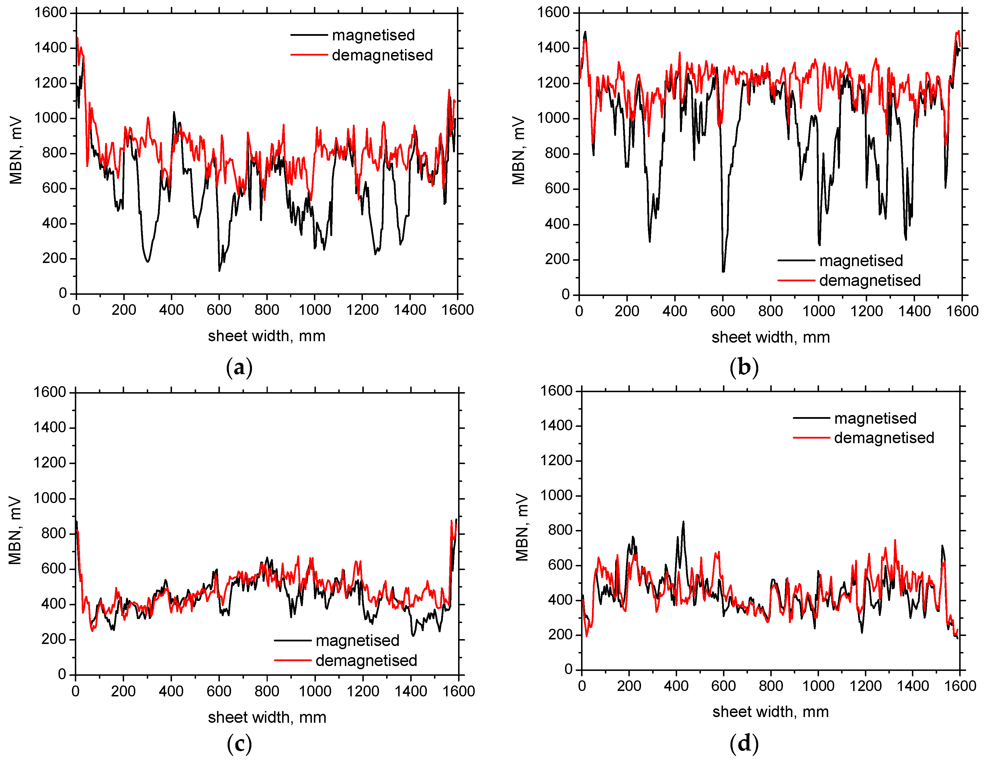
Figure 4 shows two important aspects associated with the surface and the corresponding MBN. The first is related to the valuable heterogeneity of MBN with respect to the sheet width. In particular, the regions near the sheet edge emit much higher MBN in RD. Moreover, the opposite sites (A and B) are also different, and the MBN for side B in RD is much higher than that for side A. The MBN in TD are lower, and the heterogeneity of the MBN distribution is less pronounced. The remarkable heterogeneity of MBN (especially for RD) is due to the different degrees and the extent of decarburisation in the different regions [
27]. Higher MBN is related to more developed decarburising, and vice versa.
The second aspect is associated with the differences between MBN before and after demagnetisation; see
Figure 4,
Figure 5 and
Figure 6. The MBN in RD exhibits values remarkably lower magnetised than those after demagnetisation. This difference is more pronounced for the regions emitting lower MBN. Furthermore, this behaviour is only minor in TD. The physical explanation for this effect is based on the presence of remnant magnetisation originating from the manufacturing process (probably the heterogeneity in plastic deformation, as previously reported [
23]). The motion of DWs motion in ferromagnetic bodies spreads through the matrix in the form of avalanches [
28,
29]. The neighbouring regions (or grains) are magnetically coupled [
30,
31,
32], and the change in magnetisation in a certain region triggers a similar process in the neighbouring ones. As soon as a certain region contains remnant magnetisation, DWs in this region can be remarkably attenuated or fully hindered, being magnetically coupled to the regions containing remnant magnetisation. Expressed in other words, the presence of unpinned DWs produced during manufacturing (remnant magnetisation) attenuates DWs in the magnetically coupled neighbouring regions.
Figure 4 also demonstrates the anisotropy in the remnant magnetisation, since the influence of demagnetisation prevails in RD as contrasted with TD due to the alignment of DWs in RD. Preferential alignment of DWs in certain directions favours the MBN in this direction and attenuates the MBN when the altered magnetic field is reversed [
22]; see
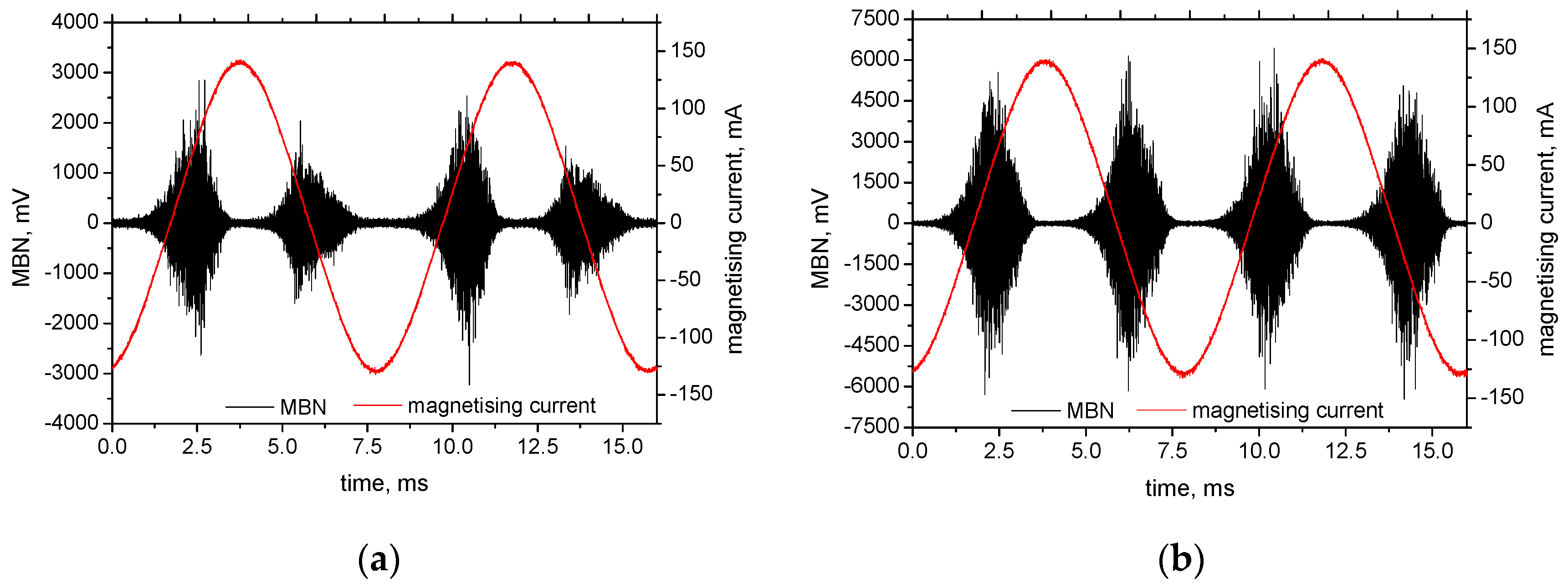
Figure 5 (the consecutive MBN bursts are different before demagnetisation).
Apart from other aspects, MBN is also a function of DWs speed motion
vp in m.s
-1 (see equation 1)
where
M is the magnetisation,
H is the altered magnetic field, and
Hc is the magnetic field necessary for the initiation of DWs motion (exponent
q is about ≈ 0.5) [
10,
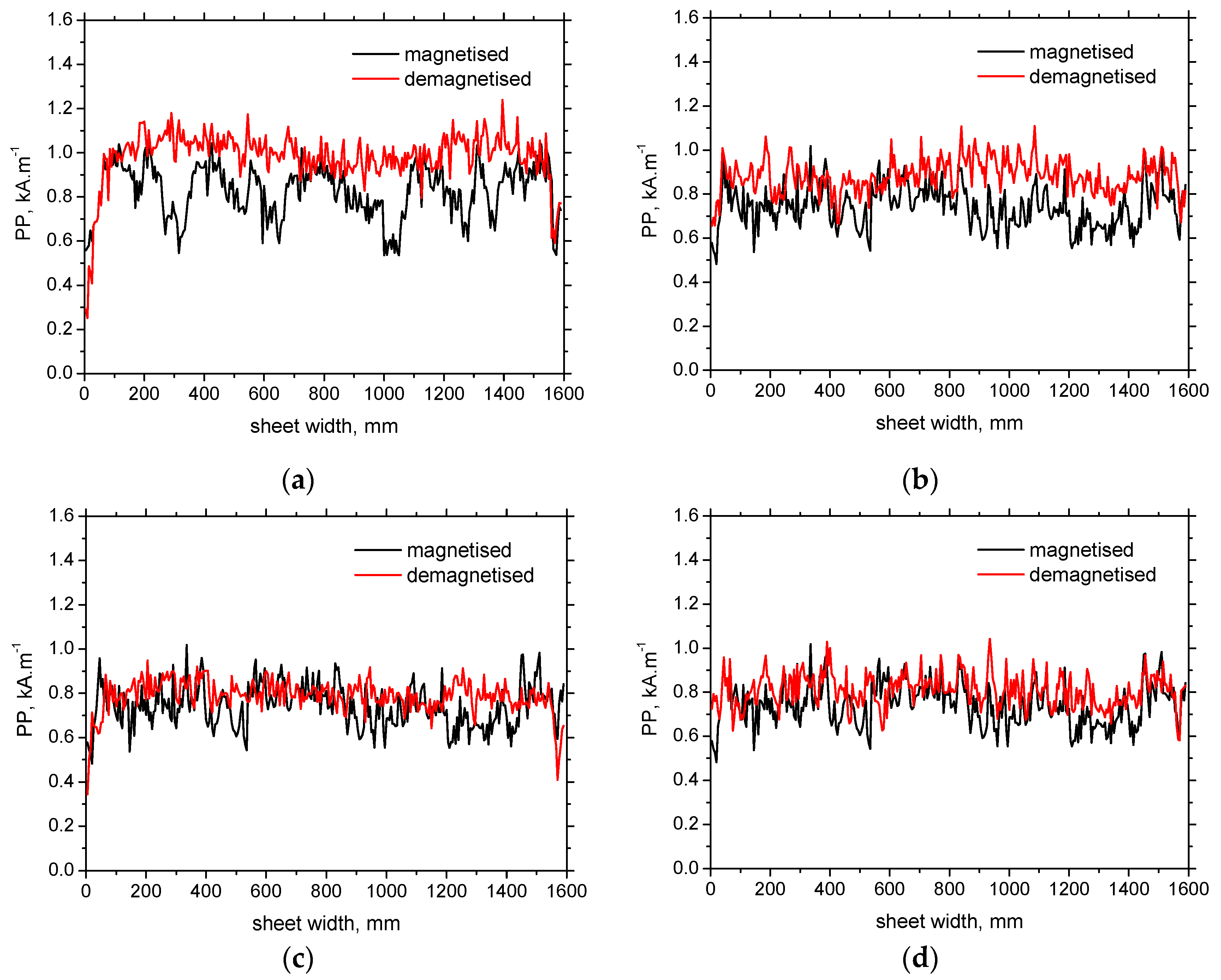
33]. Due to the presence of remnant DWs alignment,
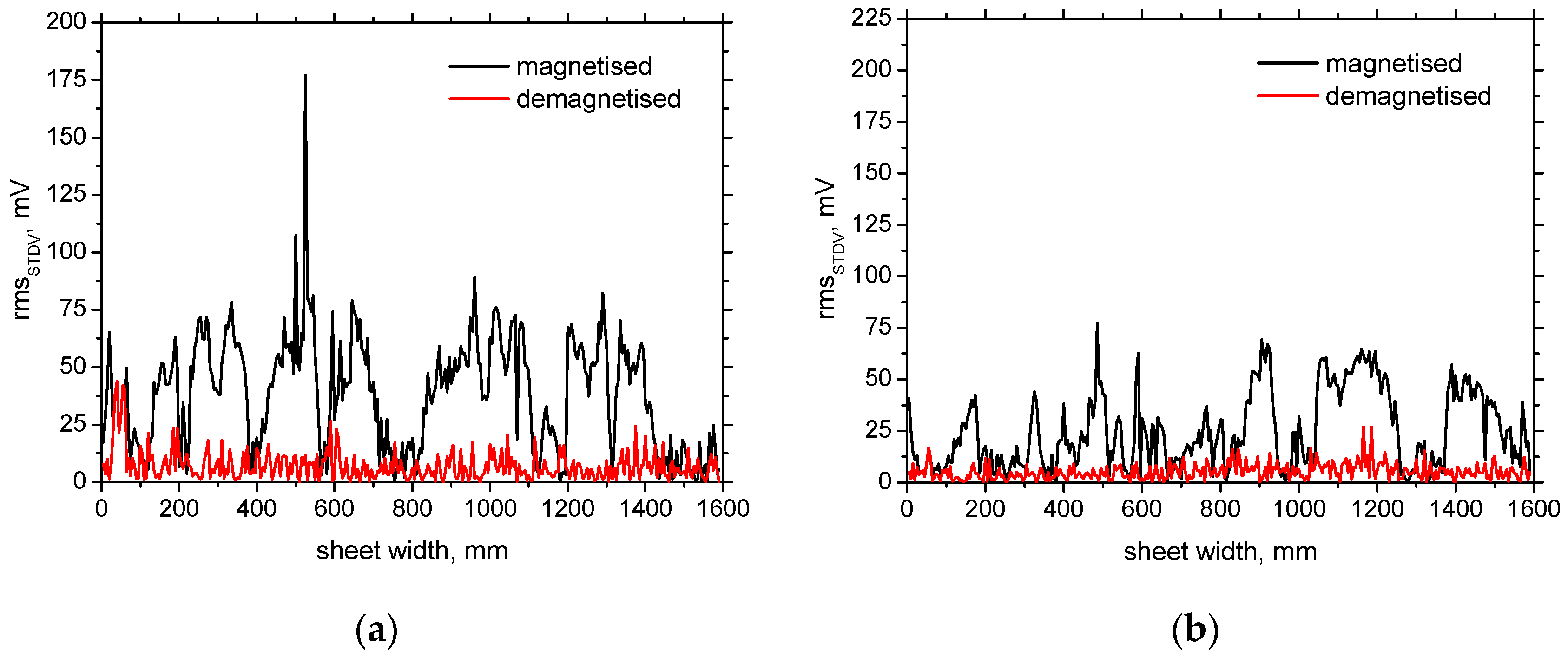
Hc in the direction of DWs alignment will be less compared to the reversed field, which in turn results in a different MBN. Furthermore, very high STDV (standard deviation) and asymmetry in consecutive MBN bursts can be found; see
Figure 5 and
Figure 6.
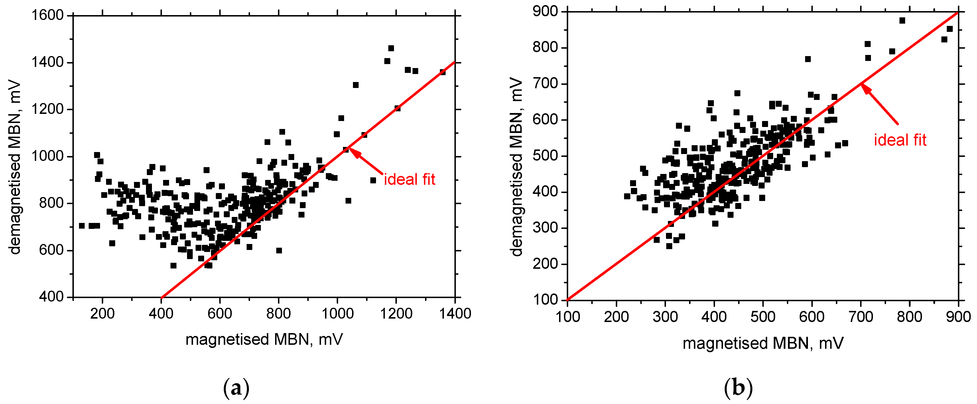
The influence of demagnetisation on MBN is more pronounced in the regions emitting the lower MBN after demagnetisation; see
Figure 7. These regions are mostly related to the less developed decarburising and the harder matrix in terms of its mechanical and corresponding magnetic hardness.
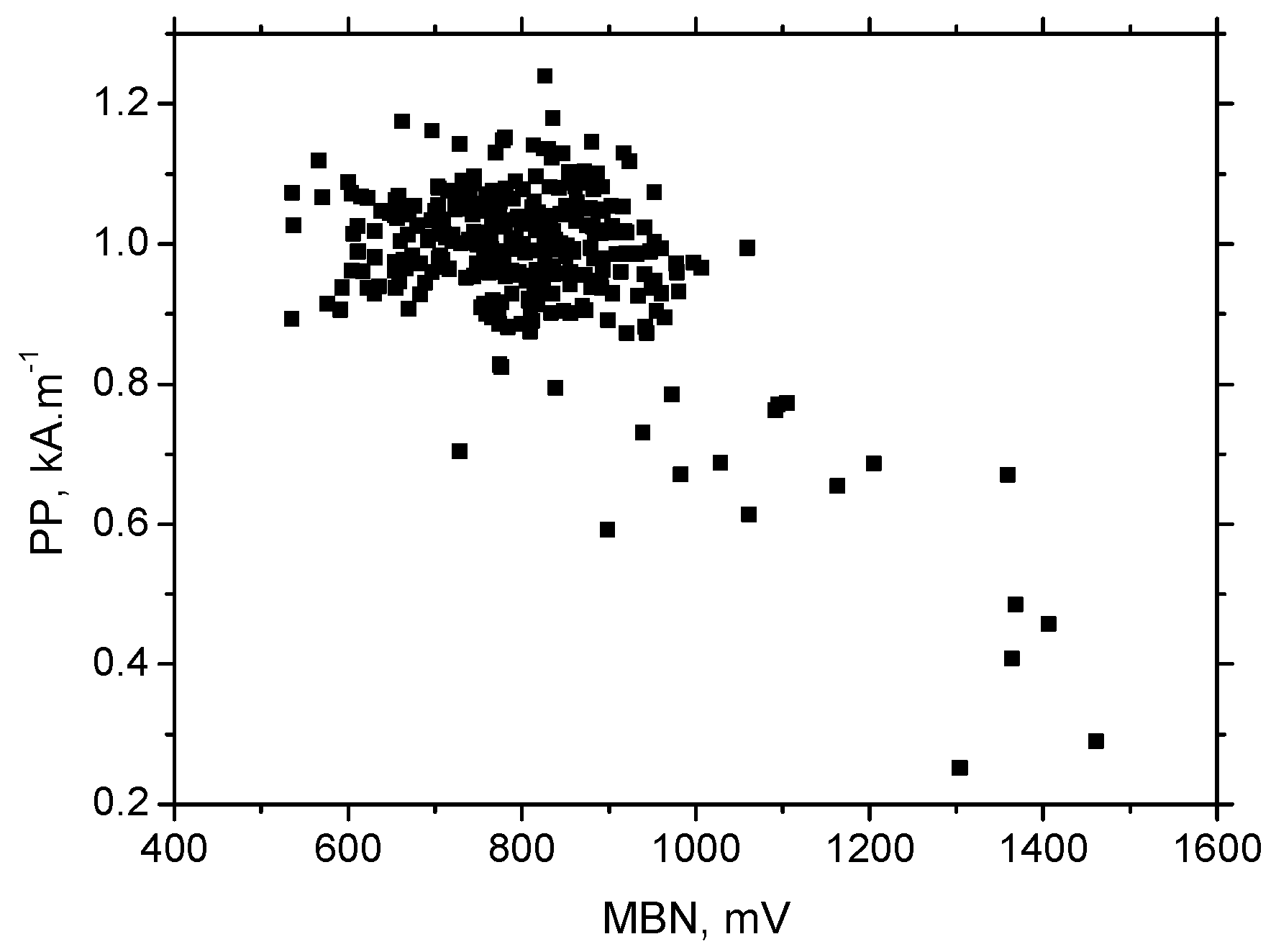
PP and MBN are very often closely related (see
Figure 8) when the high MBN is linked to the low
PP and vice versa [
11,
34]. The magnetic field necessary to unpin DWs in regions of higher dislocation density is usually higher due to the stronger opposition of dislocation tangles to the irreversible DWs motion [
11]. The weaker magnetic field is capable of removing the remnant magnetisation in the magnetically softer regions and suppresses the influence of the demagnetisation process on the MBN in contrast to regions that are harder. This is because the lower influence of demagnetisation of MBN and the extracted MBN features can be found near the sheet edges.
Figure 9 demonstrates that the aforementioned magnetic coupling and the presence of remnant magnetisation in the sheet also affect the asymmetry of MBN envelopes and the corresponding heterogeneity of
PP along with the sheet width. The presence of the remnant magnetisation makes the region magnetically softer, in contrast to the demagnetised state; see
Figure 9. This effect is more developed in RD, while TD is nearly unaffected.
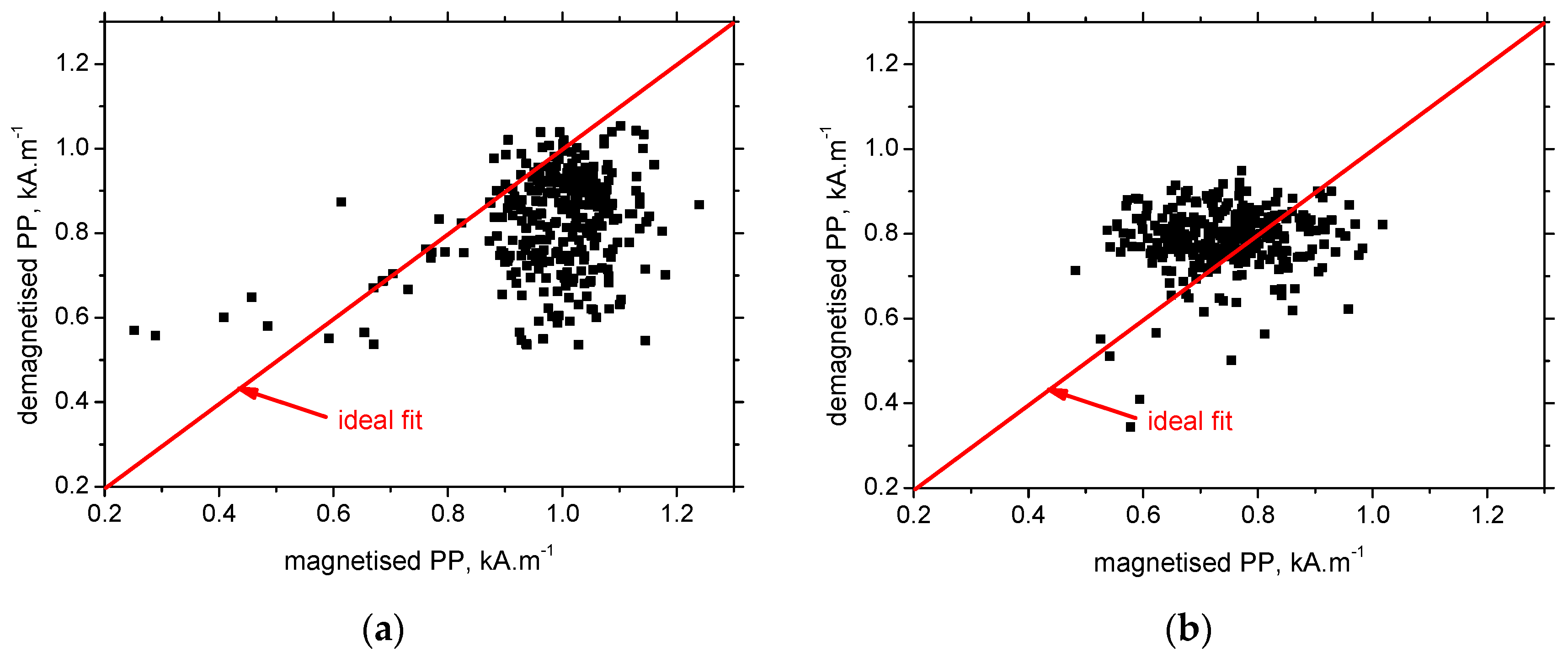
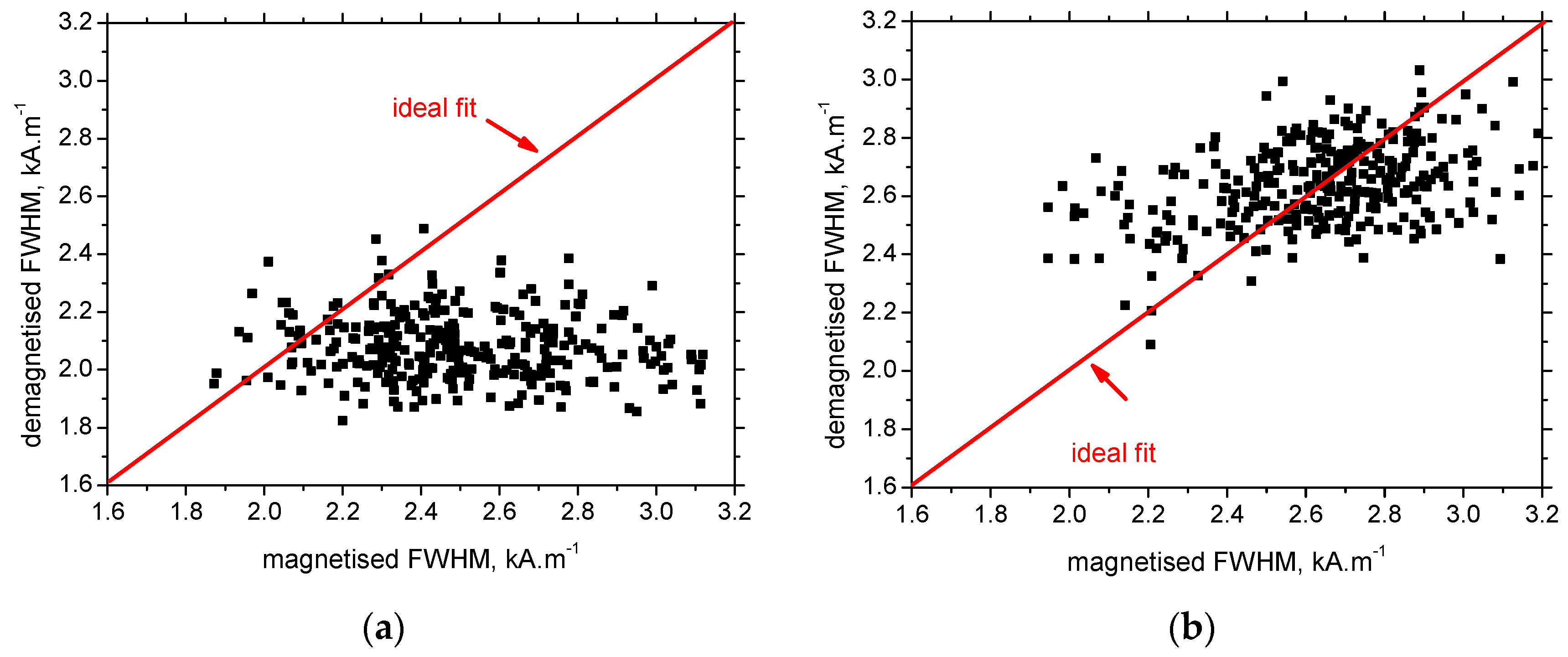
Figure 10 confirms that the contribution of the demagnetisation process is more remarkable for the region being harder, emitting lower MBN and higher
PP.
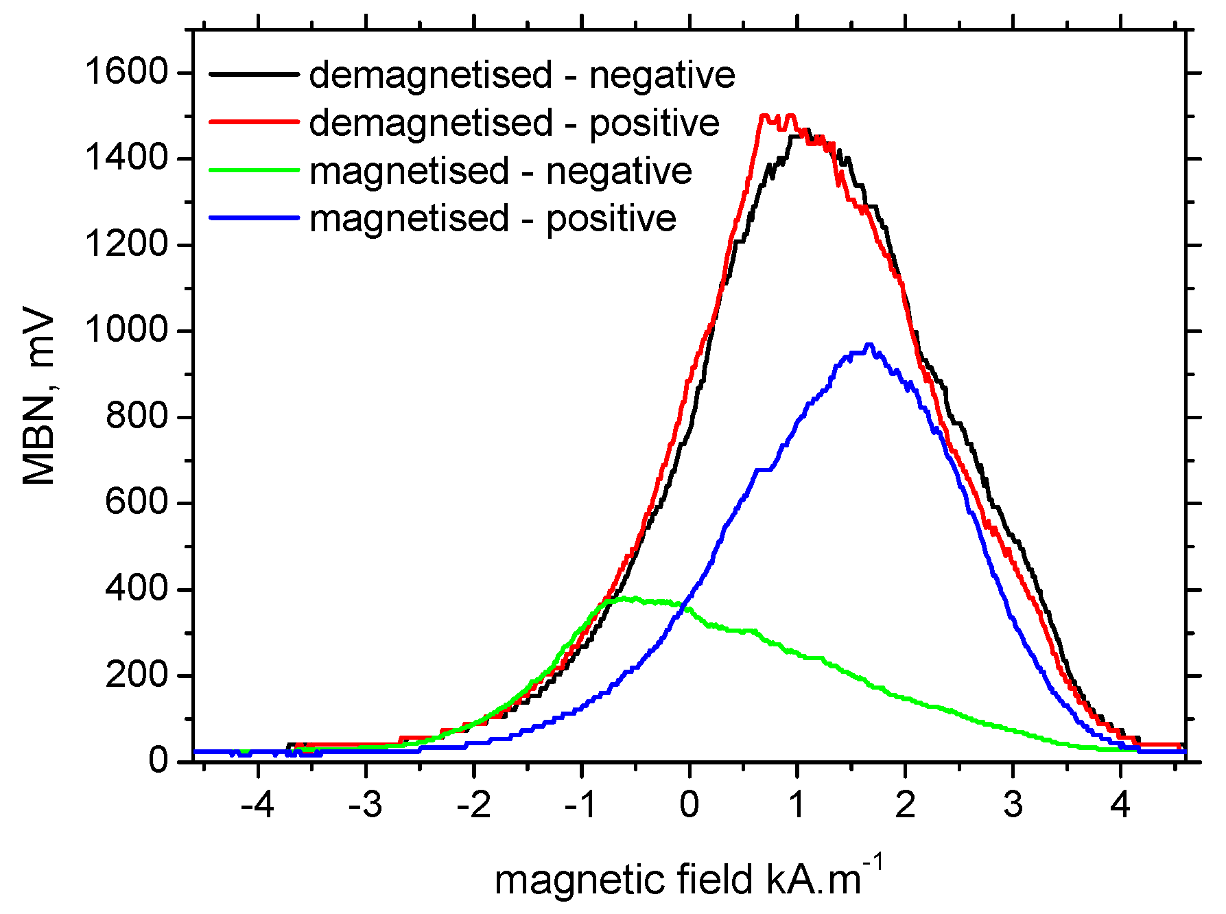
The remarkable asymmetry in the consecutive MBN bursts before demagnetisation (see
Figure 5) can be directly linked to the strong asymmetry in the MBN envelopes along the descending magnetic field (negative) and the ascending one (positive); see
Figure 11. Demagnetisation of the sample, which completely removes the remnant magnetisation, makes the MBN envelopes nearly the same with no sensitivity to the direction of the altering field. It should also be noted that
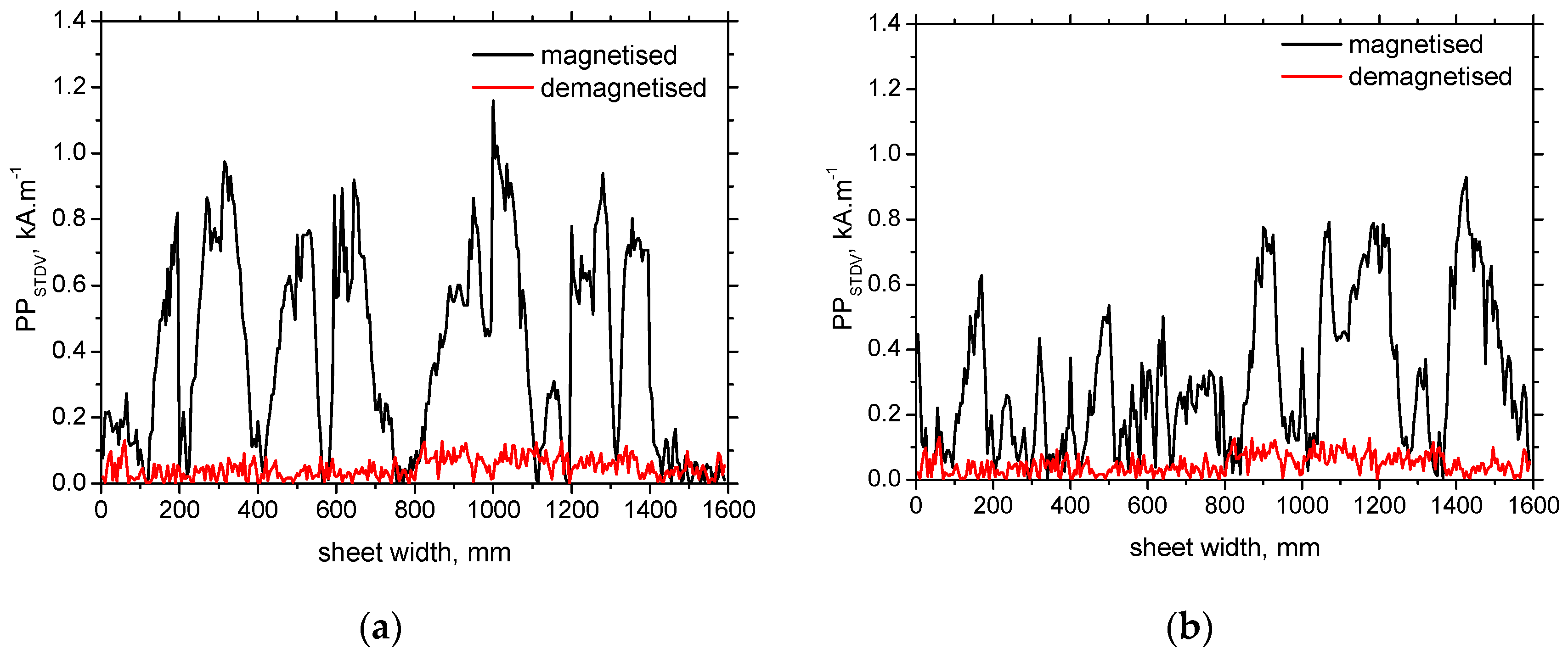
PP suffers from the presence of remnant magnetisation, most of all MBN features. The extremely high STDV of
PP (see
Figure 12) discriminates this MBN characteristic with respect to its use for the monitoring of surface state and/or stress state in real applications when the component is not sufficiently demagnetised.
FWHM is the MBN feature linked to the range of magnetic field in which MBN emission can be detected. This parameter is also quite sensitive to the exerted stress [
35]. When the preferential orientation of the matrix is developed, the conditions for the initiation of DWs in different regions (layers, grains) are very similar, MBN bursts are very narrow, and
FWHM is low [
36]. 1100 MC MBN bursts and the corresponding
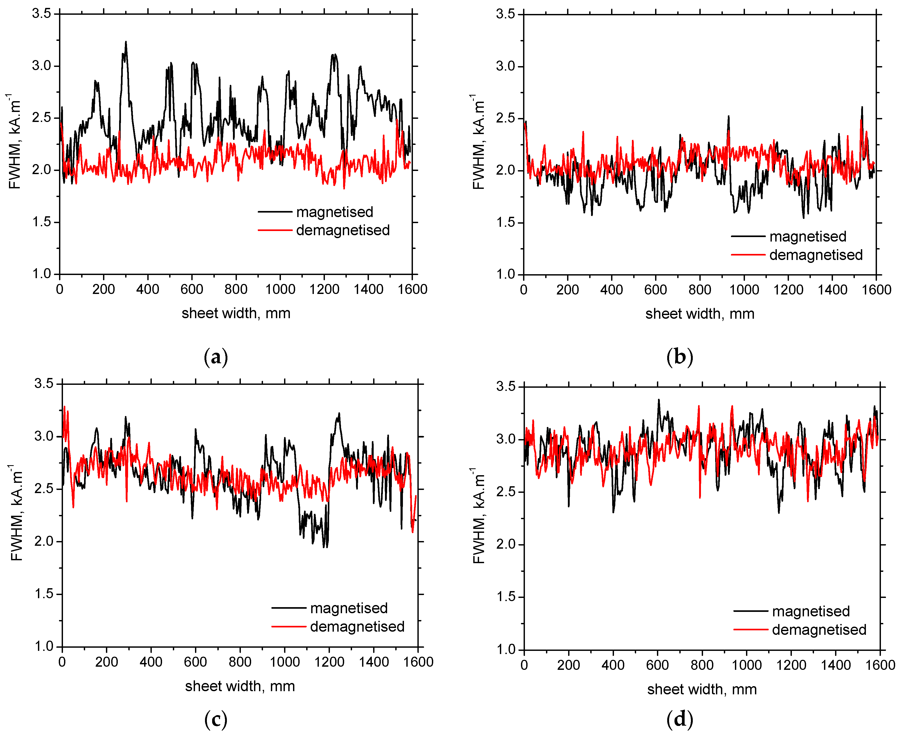
FWHM are typical for soft magnetic bodies when MBN occurs in a quite a wide range of altered magnetic fields. Moreover, due to the superimposing of the remnant magnetisation with the altered external field,
FWHM is higher (see
Figure 13), since the conditions for unpinning DWs are very heterogeneous and directionally sensitive. The directional sensitivity can be proved by the higher differences between
FWHM before and after demagnetisation along with the sheet width in RD and TD; see
Figure 13 and
Figure 14.
Requirements considering sufficient demagnetisation are associated with the magnetic field produced by the employed sensor. These fields are too weak for unpinning DWs in all regions that contribute to MBN. Therefore, preliminary demagnetisation in much stronger magnetic fields (vanishing in strength) should be carried out before MBN measurements. On the one hand, the employed sensor is capable of producing a stronger magnetic field altering in time [
37], which might suppress the asymmetry in consecutive MBN bursts. However, applications of such magnetising conditions can also result in a weaker sensitivity of MBN measurements to microstructure alterations and/or stress state, as reported in e.g. [
38,
39,
40].
4. Conclusions
The main outputs can be briefly listed as follows:
- -
the remarkable MBN heterogeneity along with the sheet width is due to the variable decarburising developed during hot rolling,
- -
the presence of remnant magnetisation makes the MBN heterogeneity more pronounced,
- -
the consecutive MBN bursts, as well as envelopes, are strongly asymmetrical,
- -
MBN asymmetry and heterogeneity are more apparent in the RD only due to the alignment of DWs in RD,
- -
the presence of the remnant magnetisation makes PP lower and FWHM higher compared to the demagnetisation state.
Monitoring HSLA steels that undergo thermo-mechanical treatment using MBN is a challenging task. On the one hand, the contribution of remnant magnetisation can be fully removed by sufficient demagnetising. On the other hand, the remarkable and variable decarburising makes monitoring stress state in real applications quite a tricky task. The contribution of altering the microstructure and superimposing the influence of stress might be difficult to unwrap and needs further research.
Author Contributions
Conceptualization, M.P., N.G., and M.N.; methodology, K.Z.; software, M.N.; validation, M.P. and N.G.; formal analysis, J.C. and K.Z.; investigation, M.P., M.N., N.G., and K.Z.; resources, N.G.; data curation, N.G. and K.Z.; writing—original draft preparation, M.P., M.N. and N.G.; writing—review and editing, J.C. and K.T.; visualization, J.C. and K.T.; supervision, N.G.; project administration, M.P. and N.G.; funding acquisition, N.G. and M.N. All authors have read and agreed to the published version of the manuscript.
Funding
This work was realized within the frame of the project VEGA project 1/0052/22. This research was also supported by the Center for Advanced Applied Science, grant number CZ.02.1.01/0.0/0.0/16_019/0000778 "Center for Advanced Applied Science" within the Operational Program Research, Development and Education supervised by the Ministry of Education, Youth and Sports of the Czech Republic.
Institutional Review Board Statement
Not applicable.
Informed Consent Statement
Not applicable.
Data Availability Statement
Data sharing is not applicable to this article.
Conflicts of Interest
The authors declare no conflict of interest.
References
- Fonstein, N. Advanced high strength sheet steels, 1st ed.; Springer International publishing, Switzerland, 2015. [Google Scholar] [CrossRef]
- Ding, H.; Zhu, G.; Xiang, Ch.; Pei, F.; Chen, J.; Wang, Y; Chen, Q. Excellent combination of plasticity and ultra-high strength in a low-alloy automotive steel treated by conventional continuous annealing. Mater. Sci. Eng. A 2020, 791, 139694. [Google Scholar] [CrossRef]
- Zhang, H.K.; Xiao, H.; Fang, X.W.; Zhang, Q.; Logé, R.E.; Huang, K. A critical assessment of experimental investigation of dynamic recrystallization of metallic materials. Mater. Des. 2020, 193, 108873. [Google Scholar] [CrossRef]
- Vervynckt, S.; Verbeken, K.; Lopez, B.; Jonas, J.J. Modern HSLA steels and role of non-recrystallisation temperature. Int. Mater. Rew. 2012, 57, 187208. [Google Scholar] [CrossRef]
- De Ardo, A.J.; Hua, M.J.; Cho, K.G.; Garcia, G.I. On strength of micro alloyed steels: an interpretive review. Mater. Sci. Technol. 2009, 25, 1074. [Google Scholar] [CrossRef]
- Wang, J.; Wang, S.; Xi, X.; Wang, G.; Chen, L. The role of copper in microstructure and toughness of intercritically reheated coarse grained heat affected zone in a high strength low alloy steel. Mater. Char. 2021, 181, 111511. [Google Scholar] [CrossRef]
- Li, S.; Yu, H.; Lu, Y.; Lu, J.; Wang, W.; Yang, S. Effects of titanium content on the impact wear properties of high-strength low-alloy steels. Wear 2021, 474–475, 203647. [Google Scholar] [CrossRef]
- Neslušan, M.; Pitoňák, M.; Minárik, P.; Tkáč, M.; Kollár, P.; Životský, O. Influence of domain walls thickness, density and alignment on Barkhausen noise emission in low alloyed steels, Sci. Rep. 2023, 13, 5687. [Google Scholar] [CrossRef]
- Jiles, D. Introduction to magnetism and magnetic materials, 3rd ed.; Taylor & Francis Group: New York, USA, 2016. [Google Scholar]
- Chikazumi, S. Physics of ferromagnetism, 2nd ed.; Oxford University Press, Oxford, 2005. [Google Scholar]
- Bayramoglu, S.; Gür, C.H.; Alexandrov, I.V.; Abramova, M.M. Characterization of ultra-fine grained steel samples produced by high pressure torsion via magnetic Barkhausen noise analysis. Mater. Sci. Eng. A 2010, 527, 927–933. [Google Scholar] [CrossRef]
- Kleber, X.; Vincent, A. On the role of residual internal stresses and dislocations on Barkhausen noise in plastically deformed steel. NDTE Int. 2004, 37, 439–445. [Google Scholar] [CrossRef]
- Neslušan, M.; Čížek, J.; Kolařík, K.; Minárik, P.; Čilliková, M.; Melikhová, O. Monitoring of grinding burn via Barkhausen noise emission in case-hardened steel in large-bearing production. J. Mater. Process. Technol. 2017, 240, 104–117. [Google Scholar] [CrossRef]
- Neslušan, M.; Minárik, P.; Čilliková, M.; Kolařík, K.; Rubešová, K. Barkhausen noise emission in tool steel X210Cr12 after semi-solid processing. Mater. Char. 2019, 157, 109891. [Google Scholar] [CrossRef]
- Yamaura, S.; Furuya, Y.; Watanabe, T. The effect of grain boundary microstructure on Barkhausen noise in ferromagnetic materials. Acta Mater. 2001, 49, 3019–3027. [Google Scholar] [CrossRef]
- Neslušan, M.; Minárik, P.; Grenčík, J.; Trojan, K.; Zgútová, K. Non-destructive evaluation of the railway wheel surface damage after long-term operation via Barkhausen noise technique. Wear 2019, 420–421, 195–206. [Google Scholar] [CrossRef]
- Neslušan, M.; Bahleda, F.; Minárik, P.; Zgútová, K.; Jambor, M. Non-destructive monitoring of corrosion extent in steel rope wires via Barkhausen noise emission. J. Magn. Mater. 2019, 484, 179–187. [Google Scholar] [CrossRef]
- Manh, T.L.; Caleyo, F.; Hallen, J.M.; Espina-Hernández, J.H.; Pérez-Benitez, J.A. Model for the correlation between magnetocrystalline energy and Barkhausen noise in ferromagnetic materials. J. Magn. Magn. Mater. 2018, 454, 155–164. [Google Scholar] [CrossRef]
- Sorsa, A.; Santa-Aho, S.; Wartiainen, J.; Souminen, L.; Vippola, M.; Leviskä, K. Effect of shot peening parameters to residual stress profiles and Barkhausen noise. J. Non-Destruct. Eval. 2018, 37, 1–11. [Google Scholar] [CrossRef]
- Liu, J.; Tian, G.Y.; Gao, B.; Zeng, K.; Zheng, Y.; Chen, J. Micro-macro characteristics between domain wall motion and magnetic Barkhausen noise under tensile stress. J. Magn. Magn. Mater. 2020, 493, 165719. [Google Scholar] [CrossRef]
- Čilliková, M.; Mičietová, A.; Čep, R.; Mičieta, B.; Neslušan, M.; Kejzlar, P. Asymmetrical Barkhausen Noise of a Hard Milled Surface. Mater. 2021, 14, 1293. [Google Scholar] [CrossRef]
- Rivas, M.; Martinéz-García, J.C.; Škorvánek, I.; Švec, P.; Gorria, P. Magnetostatic interaction in soft magnetic bilayer ribbons unambiguously identified by first-order reversal curve analysis. Appl. Phys. Lett. 2015, 107, 132240. [Google Scholar] [CrossRef]
- Pitoňák, M.; Neslušan, M.; Minárik, P.; Čapek, J.; Zgútová, K.; Jurkovič, M.; Kalina, T. Investigation of Magnetic Anisotropy and Barkhausen Noise Asymmetry Resulting from Uniaxial Plastic Deformation of Steel S235. Appl. Sci. 2021, 11, 3600. [Google Scholar] [CrossRef]
- Smallman, R.E. Modern Physical Metallurgy, 4th ed.; Butterworth-Heinemann, United Kingdom, 1985. [Google Scholar] [CrossRef]
- Kanematsu, Y.; Uehigashi, N.; Matsui, M.; Noguchi, S. Influence of a decarburised layer on the formation of microcracks in railway rails: On-site investigation and twin-disc study. Wear 2022, 504–505, 204427. [Google Scholar] [CrossRef]
- Stupakov, O.; Perevertov, O.; Tomáš, I.; Skrbek, B. Evaluation of surface decarburisation depth by magnetic Barkhausen noise technique. J. Magn. Magn. Mater. 2011, 323, 1692–1697. [Google Scholar] [CrossRef]
- Neslušan, M. Decarburising of HSLA after thermo-mechanical processing, research report n.08/2022, University of Žilina, Slovakia, 2022.
- Bertotti, G.; Fiorillo, F. Bloch wall motion in Si-Fe investigated through surface e.m.f. measurements. J. Magn. Magn. Mater. 1984, 41, 303–305. [Google Scholar] [CrossRef]
- Alessandro, B.; Beatrice, C.; Bertotti, G.; Montorsi, A. Domain wall dynamics and Barkhausen effect in metallic ferromagnetic materials. II. Experiments. J. Appl. Phys. 1990, 68, 2908. [Google Scholar] [CrossRef]
- Bohn, F.; Durin, G.; Correa, M.A.; Machado, N.R.; Pace, R.D.; Chesman, C.; Sommer, R.L. Playing with universality classes of Barkhausen avalanches. Sci. Rep. 2018, 8, 11294. [Google Scholar] [CrossRef] [PubMed]
- Hansen, U.B.; Syljuåsen, O.F.; Jensen, J.; Schäffer, T.K.; Andersen, Ch.R.; Jose, M.B.; Rodriguez-Rivera, A.; Christensen, N.B.; Lefmann, K. Magnetic Bloch oscillations and domain wall dynamics in a near-Ising ferromagnetic chain. Nat. Commun. 2022, 13, 2547. [Google Scholar] [CrossRef] [PubMed]
- Tadić, B.; Mijatović, S.; Janićević, S.; Spasojević, D.; Rodgers, G.J. The critical Barkhausen avalanches in thin random-field ferromagnets with an open boundary. Sci. Rep. 2019, 9, 6340. [Google Scholar] [CrossRef]
- Varga, R. Domain walls and their dynamics, 1st ed.; Pavol Jozef Šafárik University: Košice, Slovakia, 2014. [Google Scholar]
- Neslušan, M.; Jurkovič, M.; Kalina, T.; Pitoňák, M.; Zgútová, K. Monitoring of S235 steel over-stressing by the use of Barkhausen noise technique. Eng. Fail. Anal. 2020, 117, 104843. [Google Scholar] [CrossRef]
- Šrámek, J.; Neslušan, M.; Bahleda, F.; Zgútová, K.; Schenk, P. Influence of sample size and magnetising voltage on Barkhausen noise during bending and uniaxial tensile test. Acta Phys. Pol. A 2020, 137, 640–643. [Google Scholar] [CrossRef]
- Neslušan, M.; Mičietová, A.; Hadzima, B.; Mičieta, B. Kejzlar, P., Čapek, J., Uríček, J., Pastorek, F. Barkhausen noise emission in hard-milled surfaces. Mater. 2019, 12, 660. [Google Scholar] [CrossRef]
- MicroScan 600 operating instructions manual V.5.4b (2015-0-06), Stresstech Group, Finland.
- Neslušan, M.; Zgútová, K.; Pitoňák, M.; Kajánek, D. Influence of Magnetising Conditions on Barkhausen Noise in Fe Soft Magnetic Materials after Thermo-Mechanical Treatment. Mater. 2022, 15, 7239. [Google Scholar] [CrossRef] [PubMed]
- Jedamski, R.; Heinzel, J.; Karpuschewski, B.; Epp, J. In-process measurement of Barkhausen noise for detection of surface integrity during grinding. Appl. Sci. 2022, 12(9), 4671. [Google Scholar] [CrossRef]
- Bahleda, F.; Neslušan, M.; Pastorek, F.; Koňár, R.; Kubjatko, T. Barkhausen Noise Emission as a Function of Tensile Stress in Low-Alloyed Steels: Influence of Corrosion and Steel Strength. Appl. Sci. 2023, 13(11), 6574. [Google Scholar] [CrossRef]
Figure 1.
Bulk microstructure of HSLA 1100 MC.
Figure 1.
Bulk microstructure of HSLA 1100 MC.
Figure 2.
Metallographic images of the surface emitting different MBN in RD after demagnetisation; (a) MBN = 540 mV, (b) MBN = 1440 mV.
Figure 2.
Metallographic images of the surface emitting different MBN in RD after demagnetisation; (a) MBN = 540 mV, (b) MBN = 1440 mV.
Figure 3.
HV0.1 profiles for the positions emitting different MBN in RD.
Figure 3.
HV0.1 profiles for the positions emitting different MBN in RD.
Figure 4.
MBN along the sheet width; (a) MBN in RD - side A, (b) MBN in RD - side B, (c) MBN in TD - side A, (d) MBN in TD - side B.
Figure 4.
MBN along the sheet width; (a) MBN in RD - side A, (b) MBN in RD - side B, (c) MBN in TD - side A, (d) MBN in TD - side B.
Figure 5.
Four consecutive MBN bursts before and after demagnetisation – side A; (a) before demagnetisation – MBN 302 ± 32 mV, (b) after demagnetisation – MBN 850 ± 5 mV.
Figure 5.
Four consecutive MBN bursts before and after demagnetisation – side A; (a) before demagnetisation – MBN 302 ± 32 mV, (b) after demagnetisation – MBN 850 ± 5 mV.
Figure 6.
STDV of MBN before and after demagnetisation – side A; (a) RD, (b) TD.
Figure 6.
STDV of MBN before and after demagnetisation – side A; (a) RD, (b) TD.
Figure 7.
MBN after demagnetisation versus MBN before demagnetisation; (a) MBN in RD - side A, (b) MBN in TD - side A.
Figure 7.
MBN after demagnetisation versus MBN before demagnetisation; (a) MBN in RD - side A, (b) MBN in TD - side A.
Figure 8.
PP versus MBN after demagnetisation - RD, side A.
Figure 8.
PP versus MBN after demagnetisation - RD, side A.
Figure 9.
PP along the sheet width. (a) PP in RD - side A, (b) PP in RD - side B; (c) PP in TD - side A, (d) PP in TD - side B.
Figure 9.
PP along the sheet width. (a) PP in RD - side A, (b) PP in RD - side B; (c) PP in TD - side A, (d) PP in TD - side B.
Figure 10.
PP after demagnetisation versus PP before demagnetisation; (a) PP in RD - side A, (b) PP in TD - side A.
Figure 10.
PP after demagnetisation versus PP before demagnetisation; (a) PP in RD - side A, (b) PP in TD - side A.
Figure 11.
MBN envelopes before and after demagnetisation; before demagnetisation MBN 302 ± 32 mV and after demagnetisation MBN 850 ± 5 mV.
Figure 11.
MBN envelopes before and after demagnetisation; before demagnetisation MBN 302 ± 32 mV and after demagnetisation MBN 850 ± 5 mV.
Figure 12.
STDV of PP before and after demagnetisation – side A; (a) RD, (b) TD.
Figure 12.
STDV of PP before and after demagnetisation – side A; (a) RD, (b) TD.
Figure 13.
FWHM along the sheet width; (a) FWHM in RD - side A, (b) FWHM in RD - side B, (c) FWHM in TD - side A, (d) FWHM in TD - side B.
Figure 13.
FWHM along the sheet width; (a) FWHM in RD - side A, (b) FWHM in RD - side B, (c) FWHM in TD - side A, (d) FWHM in TD - side B.
Figure 14.
FWHM after demagnetisation versus FWHM before demagnetisation; (a) FWHM in RD - side A, (b) FWHM in TD - side A.
Figure 14.
FWHM after demagnetisation versus FWHM before demagnetisation; (a) FWHM in RD - side A, (b) FWHM in TD - side A.
Table 1.
Chemical composition of 1100 MC in wt%.
Table 1.
Chemical composition of 1100 MC in wt%.
| Fe |
C |
Mn |
Si |
P |
S |
Al |
Nb + Ti |
| bal. |
<0.15 |
<1.8 |
<0.5 |
<0.02 |
<0.005 |
>0.015 |
0 |
|
Disclaimer/Publisher’s Note: The statements, opinions and data contained in all publications are solely those of the individual author(s) and contributor(s) and not of MDPI and/or the editor(s). MDPI and/or the editor(s) disclaim responsibility for any injury to people or property resulting from any ideas, methods, instructions or products referred to in the content. |
© 2023 by the authors. Licensee MDPI, Basel, Switzerland. This article is an open access article distributed under the terms and conditions of the Creative Commons Attribution (CC BY) license (http://creativecommons.org/licenses/by/4.0/).
