1. Introduction
The subject of interest of this work is explaining the impact of geometric configuration of the human vocal tract (hereinafter referred to as the VT) on the distribution of acoustic energy on the frequency spectrum of vocal speech. For voice teachers, it is necessary to analyse the procedures facilitating the impact of geometric configuration of the VT to amplify acoustic energy values in the required frequency range [
1,
2]. In order to shed light on such modifications of human VT on the characteristics of vocal speech, it is necessary to assemble mathematical calculation models enabling effective examination of sensitivity on individual geometric changes in the VT [
3,
4]. Assembling a fully parametric model at the level of describing boundary surfaces defining the examined acoustic system with regard to the complexity of the VT is a very demanding problem [
5,
6,
7]. Currently, the FEM is almost exclusively used for analysing the acoustic characteristics of VT, the computation complexity of which increases with the number of finite elements used, which discredits the examined volume of the acoustic system. Direct geometric reconfiguration at the level of the finite element mesh represents a very complex problem, which requires a detailed analyses of the derived model [
8]. However, due to the computation demands, such models are oftentimes not suitable for subsequent optimization tasks, whose aim it is to finetune the acoustic characteristics of phonation to the required parameters.
One of the possible approaches for assembling effective computation models is to use the super-elements method [
9,
10], which allows for modifying the analysed acoustic system only at the point of the geometric change. To speed up the calculation, the mesh of individual elements is reduced at the level of mass, damping and stiffness matrices to a number of degrees of freedom (hereinafter referred to only as “DoF”) ensuring compliance of the frequency characteristics of a full and reduced model in the frequency range, which is important for the comprehension of voice speech.
The article also presents an alternative, yet very effective approach to assembling an isoparametric element of a higher polynomial, using typical VT geometric configuration. Such an element even allows parallel acoustic cavities to be connected. Formulating the calculation model for [a:] was subsequently used to examine the permissible geometric modifications of VT, aimed at connecting the 3rd and 4th formant and shifting it into the 2.5kHz – 3.5kHz frequency range. Bringing the formants closer together makes it possible to significantly increase the amount of acoustic energy in the field of the so-called singing formant.
2. Finite Element Model of the Vocal Tract
The VT geometry is unique for every individual. A human’s ability to change the size and shape of the VT cross-section in different places, allows us to modulate the basic signal generated by the vocal cords and create different sounds. For the purpose of VT modelling, VT geometry [
11] and [
12] were measured. The CT LightSpeed VCT GE-64 was used for imaging. The measurement resulted in 181 sections, 0.625mm thick. The image resolution is 512x512 pixels. It was measured in the supine position, while sounding out [a:]. The geometric model was created by analysing sagittal CT cross-sections. The surface of the geometric model is used to create the FEM of the VT model (
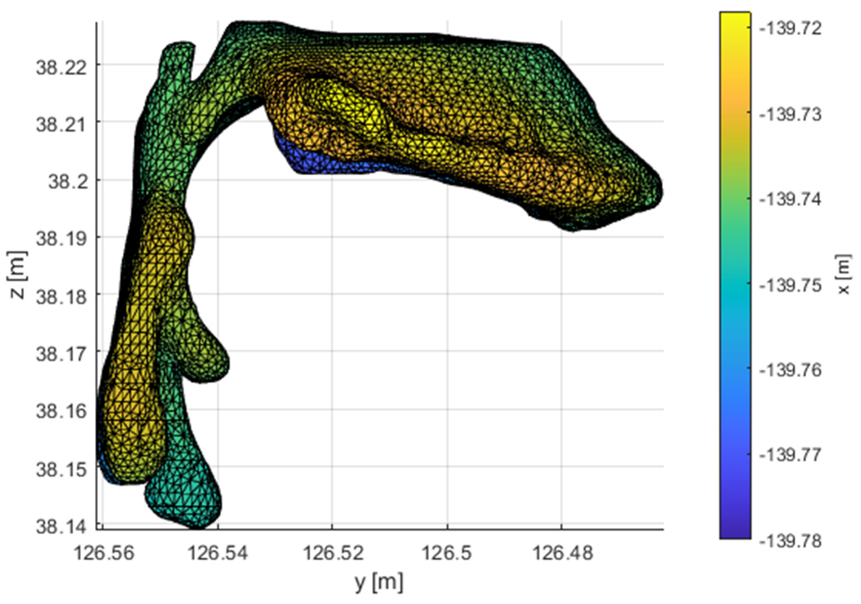
Figure 1). The geometric model contains the parallel cavities of the piriform sinuses and the epiglottic vallecula.
The formulated calculation model for [a:] was then used to examine the permissible geometric modifications of the VT, with the aim of connecting the 3rd and 4th formants and shifting them into the 2.5kHz – 3.5kHz frequency range. Bringing these formants closer together makes it possible to significantly increase the amount of acoustic energy in the field of the so-called singing formant.
The foundation of FEM is the discretization of the solved domain with the finite number of elements, which disjointly fill the entire solved volume of VT. The mathematical description of the elements is provided by the
, shape functions, which distribute the nodal values of the unknown quantities into the element’s entire volume. Multiplying by the column vector of the nodal values of the sound pressure of element
results in the following acoustic pressure distribution function in the volume of the element
The finite element method uses a so-called weak formulation and the Galerkin Method [
13]. The differential equation of the strong formulation is a scalarly multiplied by testing
function and the resulting expression is integrated via the solved volume
where
is the density of the environment,
is the velocity of sound,
is the volume damping coefficient,
is the element volume and
is the Laplace operator. The acoustic pressures and their variations expressed using nodal values and their values are put into the equation. The equation is converted into the frequency domain and Green’s first identity is applied. The pressure gradient in the resulting surface integral can be expressed using acoustic velocity
where
is the angular frequency,
is the nabla operator,
is the unit normal to the boundary
and
is the acoustic velocity. The expressions can be simplified as follows
where the
is the element’s mass matrix
the
is the element’s damping matrix (the relationship between the specific acoustic impedance
and acoustic velocity
was applied here)
the
is the element’s stiffness matrix
and
is the vector of the right sides
Relationship (4) mathematically defines the acoustic properties of one element. After discretization of the space of finite elements, global matrices describing the whole system solved are then assembled.
Figure 1 illustrates the FEM mesh model of the VT for vowel [a:]. This model has a total of 36553 nodes. The mesh model is not structed and the types of elements used are quadratic tetrahedrons with ten nodes. There are 186570 elements in the model. The model is created using commercial software Ansys.
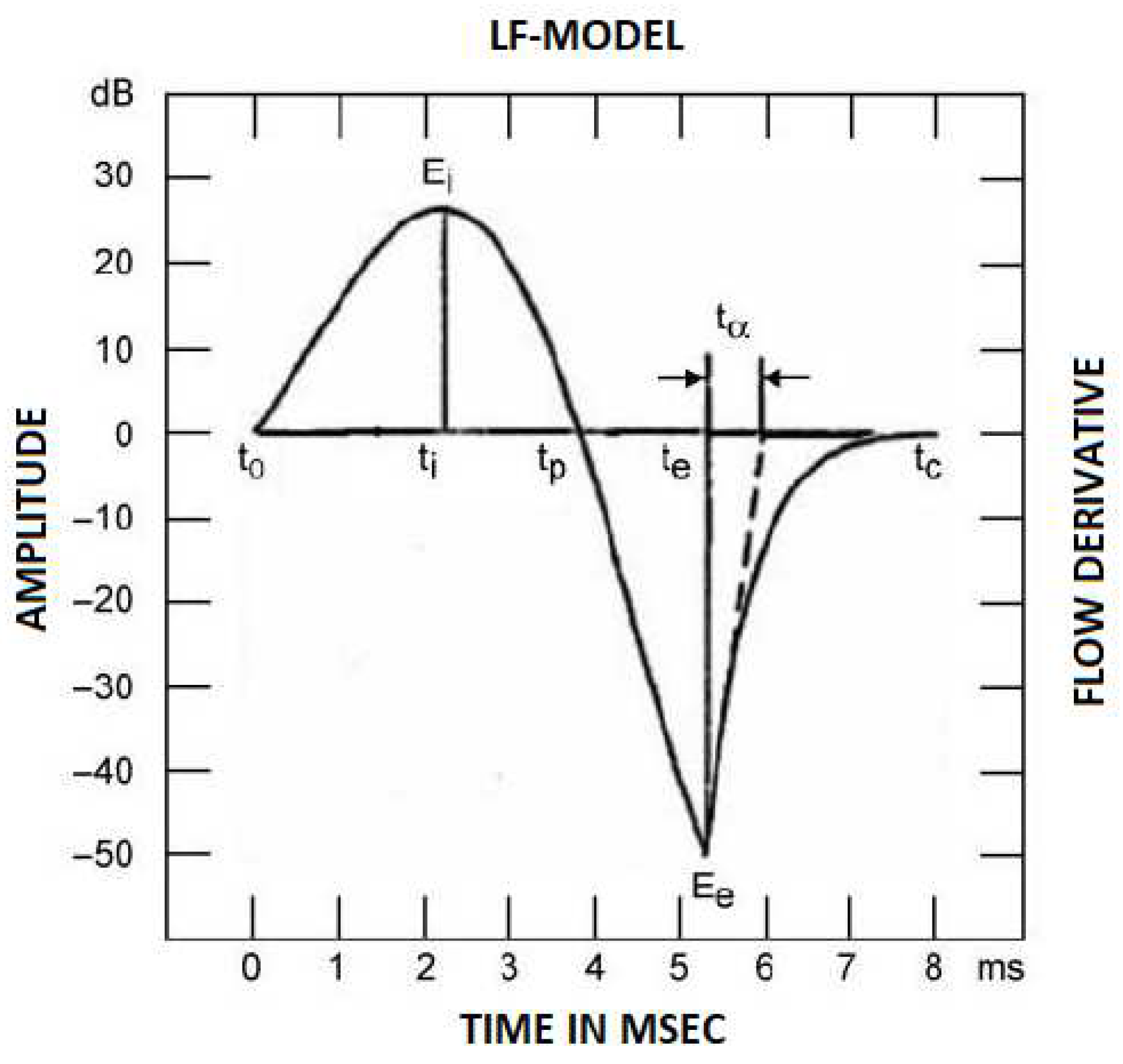
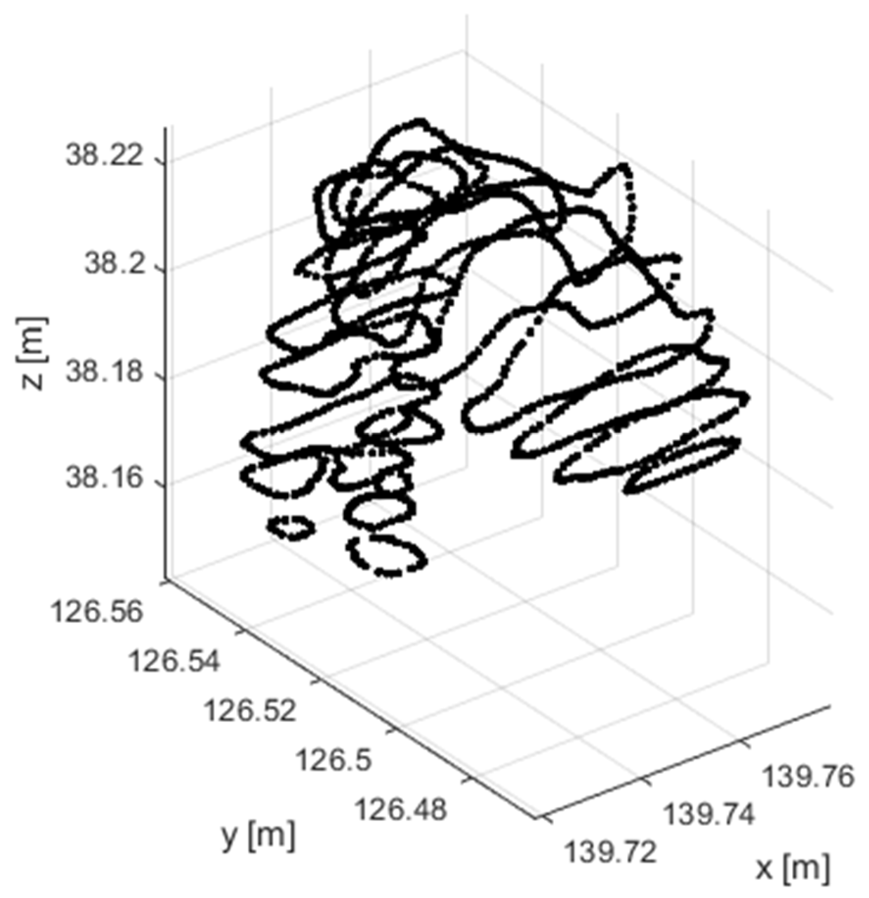
Air flow is not stationary due to vocal cord oscillations. The air flow volume is periodic and can be approximated using an analytical model. The Liljencrants-Fant model (L-F model) [
14] is one of the basic models of air pulses. This model has four parameters. The first derivative of this pulse is in
Figure 2. A velocity-type boundary condition is modelled at the level of the vocal cords.
Acoustic energy is emitted by the mouth into the surrounding space. The external environment model is replaced by the emitted acoustic impedance. This is derived under the assumption of a circular oral opening, constant acoustic velocity throughout the oral opening and an infinite external environment [
15]. In such a case, the specific acoustic impedance at the output of the VT can be defined by the following relationship.
where
and
are the first order Bessel and Struve functions and
is the radius of the considered oral opening. The disadvantage of this procedure is the non-linear frequency dependance of the acoustic impedance.
A disadvantage of the described FEM model is the large number of DoF. The dimensions of the model’s mass, damping and stiffness matrices equal to the number of the DoF model. Although the matrices are symmetrical and sparse, their dimensions are generally so large (in this case: 36 553) that the model can be described as very computationally demanding. The computation demands depend on the type of analysis, the computer’s performance and the performance optimization of the solver.
3. Aim of This Work
Calculating the sensitivity of acoustic properties on the geometric modifications of the VT or calculating the optimal geometry VT for achieving the required properties are important tasks for clinical practice. Such tasks are generally more demanding and are oftentimes solved using optimization approaches, which require ample calculations given various modification models. The number of analyses is then considerable, requiring more time for calculations.
The aim of this work is to optimize the model’s computation demands, allowing complex optimization calculations to be done. The first procedure uses concept of super-elements obtained by reducing an extensive FEM model divided into smaller subsystems. The second method uses a specially designed element for FEM. This element is designed in such a way so that it enables the discretization of the VT geometry. The models assembled using this element have a very low number of DoF. They only contain the necessary nodes on the surface of the model for defining the geometry and nodes on the curve passing through the centre of the VT cross-section. Both procedures generate models with a similar number of DoF and node spacing.
4. IRS Reduction
The commonly used method for reducing the computing demands of large models are reductions at the level of the M and K matrices. The principle consists in decreasing the number of DoF. The resulting reduced model can be understood as one super-element. The basic reduction method is the Guyan Reduction Method [
16], which is generalized by the IRS (improved reduced system) reduction.
IRS reduction is based on a model containing stiffness and mass matrices. The model’s DoF is divided into those that are preserved,
and those that are reduced,
[
17]
The mathematical model transforms into the following shape
For the reduction, it is necessary to find map
in the
set. This is ensured by transformation matrix
by the following relationship
Transformation matrix
is used to transform the whole mathematical description into the reduced DoF
is defined by the following relationship [
18]
where
is the transformation matrix of the static Guyan reduction
and matrix
is defined by the following relationship
The formula for
is implicit because it depends on the reduced system. Therefore, it has to be calculated iteratively. The first iteration step is solved using the Guyan reduction
. After obtaining the first reduced mass and stiffness matrices, iteration can continue using the IRS method
The convergence of this iteration scheme is accelerated if
is replaced by
in the second part. The model’s final reduction matrix is determined after the convergence. The shape of the model is then
5. Properties of IRS Reduction
The derivation of IRS reduction [
18] utilizes simplified assumptions, which cause errors in the calculated model. This error depends on the amount and location of the reduced and preserved nodes and on the number of iterations of the IRS method. Therefore, the IRS reduction effect test is conducted on the model’s properties. The motivation to use reduction methods to modify models was to reduce computation demands, which allow optimal calculations to be carried out in reasonable times. The expression for the IRS method transformation matrix is implicit and is solved iteratively, thus making the calculation more complex. Therefore, the convergence test of the IRS iteration scheme was conducted. This test is important for optimally selecting the number of iterations, which guarantee compromise between computation demands and the generated error.
The dominant frequency formants are used to study the importance of VT for forming vowels. From the acoustics viewpoint, the formant is a local frequency extreme in the voice spectrum, which is created by amplifying the acoustic pressure by transfer function of the VT between the vocal cords and the mouth. These local extremes are always in the area around eigenfrequency of the acoustic oscillations of the solved geometry. Therefore, the task then turns into finding eigenfrequencies.
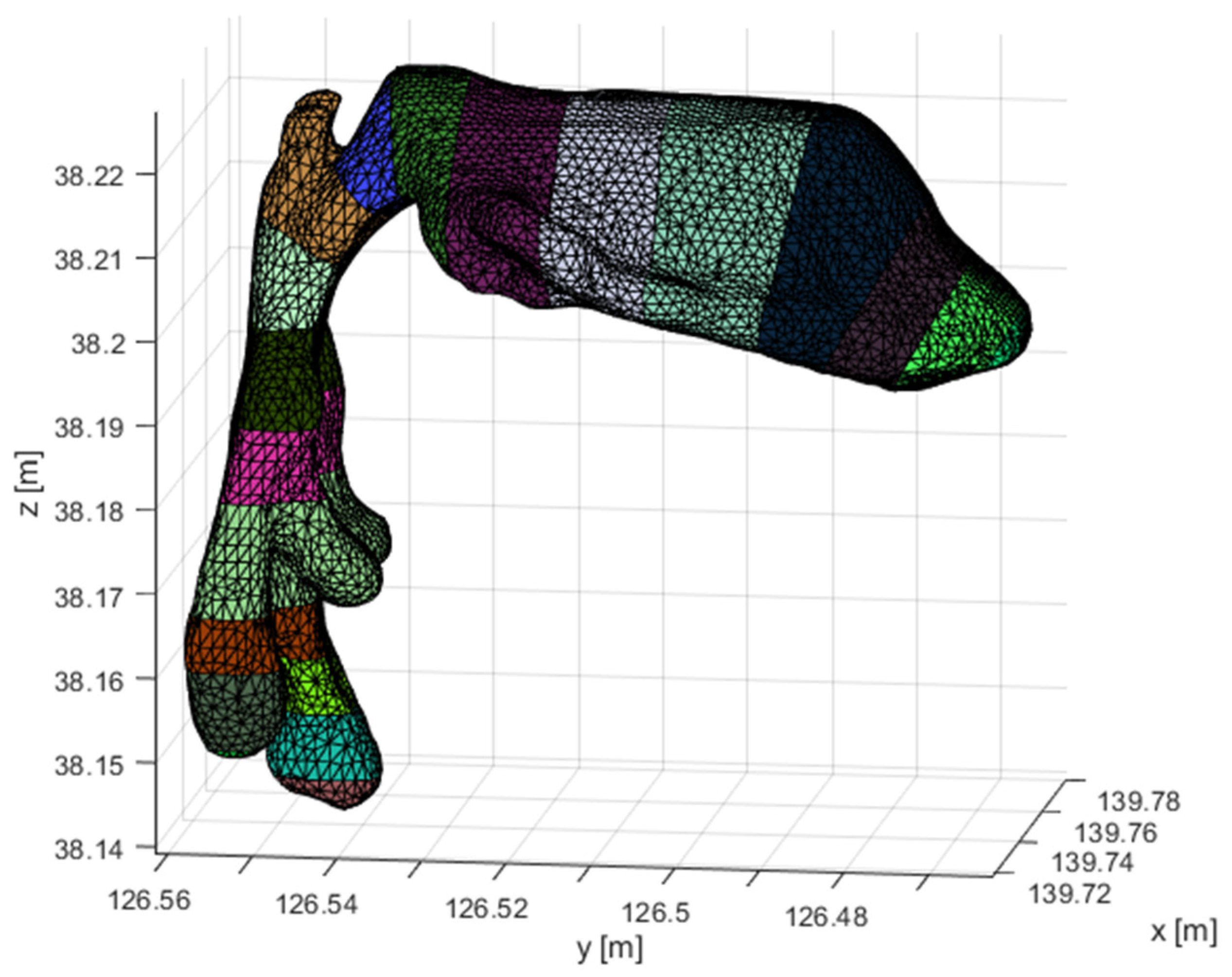
For the purposes of this work, the geometric model of the measured VT had to be divided into subsequent volumes. The cross-sections are always planar and the resulting geometry is illustrated in
Figure 3. The main VT cavity is made up of 16 volumes. Furthermore, the model contains another two parts forming the piriform sinuses and 4 parts that close the model. The vallecula are one part of the main cavity. All parts of the divided VT were reduced by the IRS method. The aim of the reduction was to only preserve the nodes at the intersection of the dividing planes with the VT surface. This reduced the total number of DoF from 36553 to 1154. Almost 97% of the model size is reduced.
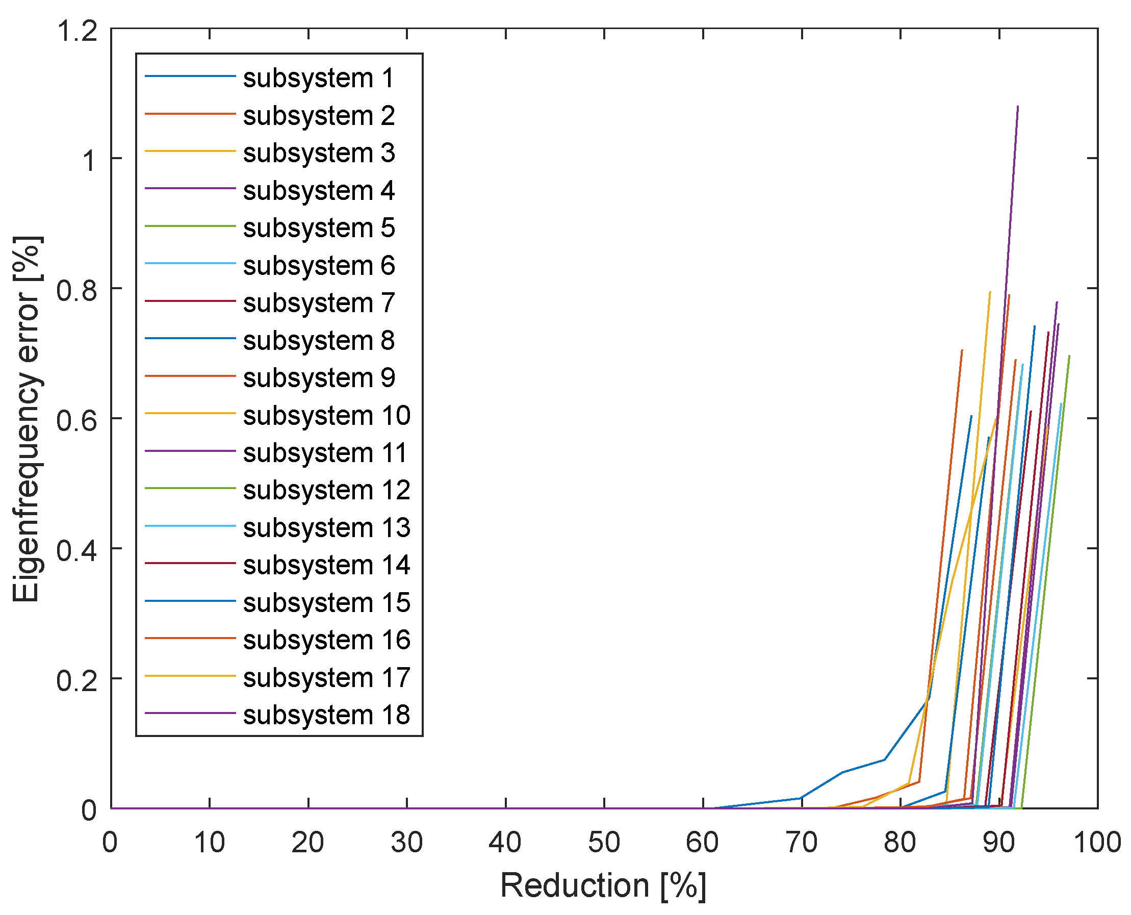
Figure 4 illustrates the size of the relative error of eigenfrequency models in relation to the number of reduced DoF. These graphs are used to evaluate the smallest eigenfrequencies for every VT part and every analysed degree of reduction. To reduce the amount of data in the image, the eigenfrequency with the worst result is always displayed. It can be seen that there is practically no error up to a reduction of 70%-80% DoF. In the case of only preserving the DoF on the perimeter of the dividing surface, the errors are in tenths of percent. Different degrees of reduction were achieved at different parts of the VT. This is given by the fact that the ratio between the number of preserved DoF and the total number of DoF is different. In some parts, only 86% of DoF were reduced and maximum reduction reached 97%.
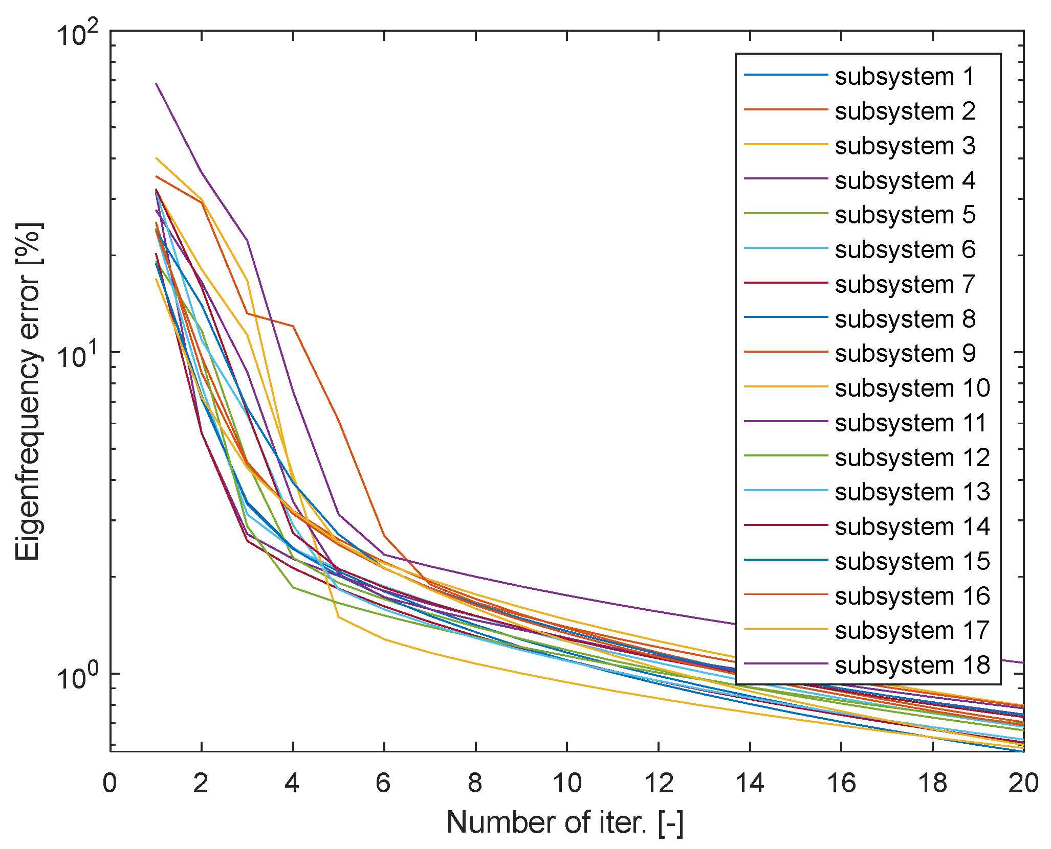
The computation times increase with the number of iterations. The optimal number of iterations was determined by a numerical experiment. The relative error of eigenfrequency was monitored depending on the number of iterations (
Figure 5). The eigenfrequencies were re-evaluated and the worst result was always used for illustration purposes. The error is up to 68% after the first iteration and the average error is approximately 20%. The error decreases steeply with the number of iterations. The decrease decelerates after the fifth iteration. The error does not exceed 1.7% after the 10th iteration and the maximum error after the 20th iteration is 1.08%.
The test conducted using the IRS method only evaluated eigenfrequency, showing a low distortion of results. After the IRS reduction, the model has a lower number of DoF and thereby even a lower number of eigenfrequencies and oscillation shapes. The IRS preserves the lowest frequency. The model preserves the lowest eigenfrequency even when it does not contain the nodes necessary to describe the respective oscillation shape.
Super-elements for all parts of the VT were created. According to
Figure 3, this represented a total of 22 super-elements, based on which the entire VT calculation model was assembled.
Such a created model has 1154 nodes (
Figure 6), which represents about 3% of the original model. The model’s computation demands increase with its size faster than linearly. The processing time savings are high. In this case, no emitted acoustic impedance was used at the level of the mouth. This boundary condition was modelled as the null sound pressure. This can be interpreted as emission without any losses. The quality of the results is evaluated by comparing the values of eigenfrequencies. The frequencies of the reduced models are as follows
Using super-elements and reduction methods confirmed the applicability for decreasing computation demands. Comparing the size of the original model with the reduced model is not sufficient for evaluating the effectiveness of these procedures. It is also necessary to evaluate the computation demands of the reduction itself and the number of runs of the created model. If the number of runs of the reduced calculation model is high, it can be assumed that this procedure is worthwhile. However, it is necessary to add up the reduction demands for a single run and any subsequent calculations. Before starting the iteration, it is necessary to calculate and it is necessary to calculate the reduced mass and stiffness matrices (simply by multiplying the matrices) and invert the reduced mass matrix for every iteration. Most of the computing time during the IRS is spent on these inversions. The matrix is square-shaped with a dimension corresponding to the number of reduced DoF. On the contrary, the dimension of the reduced mass matrix is the same as the number of preserved DoF. If the number of reduced DoF is relatively low, calculating is not demanding but repeatedly calculating is very demanding. On the contrary, if the DoF is primarily reduced, then calculating is demanding and calculating is not demanding. Generally speaking, a reduction in which less DoF are preserved is even more effective from the viewpoint of the demands of the reduction itself. In this case, approximately 97% of the DoF are reduced, which means that the dimensions of the matrix is almost the entire stiffness matrix. If the majority of the DoF are reduced, then the demands correspond to the number of inversions of the stiffness matrix. This calculation is comparable to the demanding calculations of general eigenvalues or eigenfrequencies. The IRS method of creating super-elements is only practical when the resulting model is to be used repeatedly. In addition, implementing IRS reduction makes most modifications of the model impossible.
6. The Designed Isoparametric Element
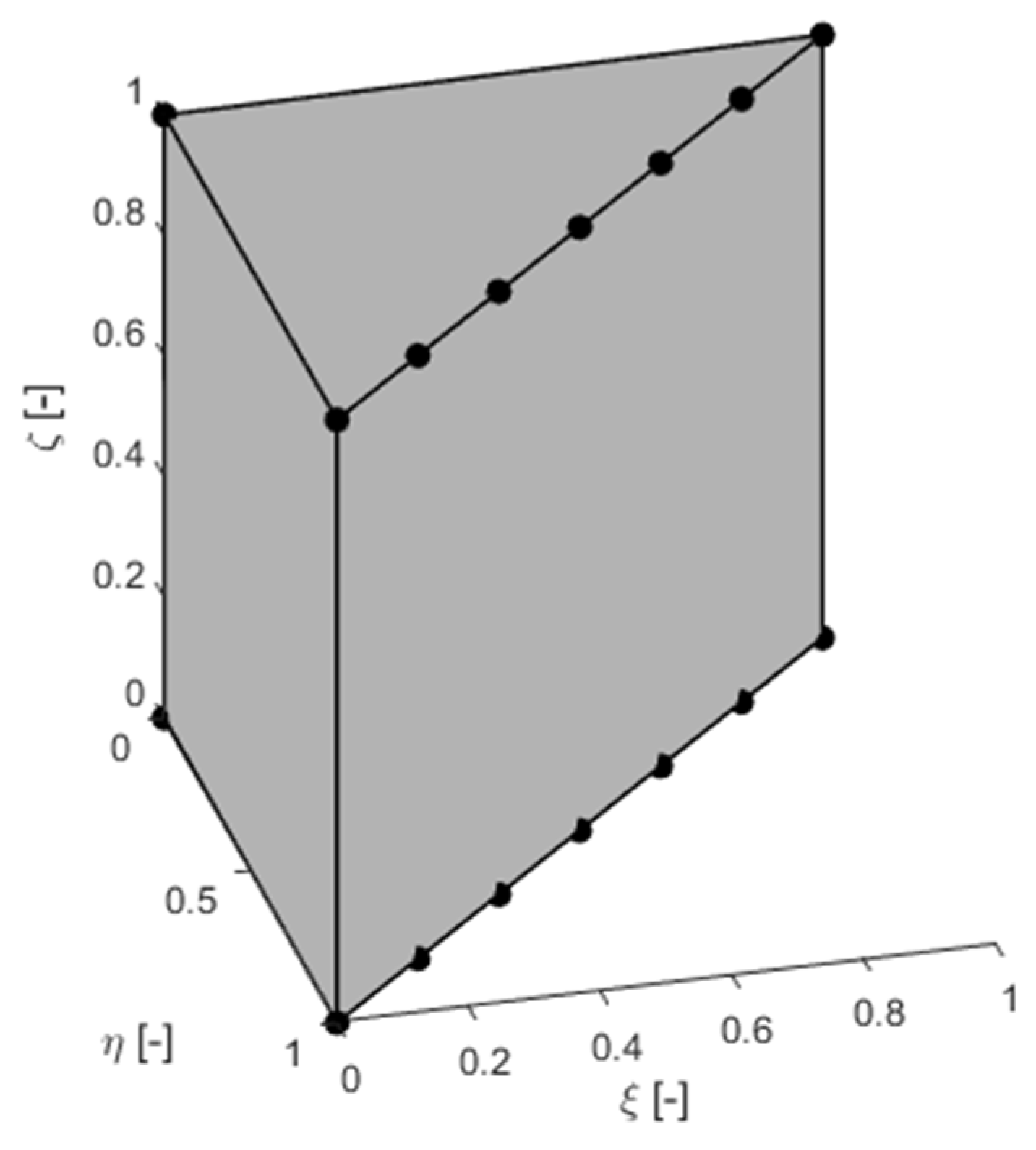
The human vocal cord has a characteristic geometry, which can be described as a curved canal, with a dominant longitudinal dimension and less dominant transverse dimensions. The cross-section is different from the circular one. The requirements for a new FEM element are that it is suitable for VT discretization given the model’s low number of DoF. With regard to the defined requirements, the designed element has a triangular base in the reference state, which extends to the third dimension (
Figure 7). The triangular base is based on the shape functions of a higher degree polynomial but most of the nodes are analytically eliminated. The base only has nodes at the vertices and in one wall.
The element’s topology is chosen in such a way, so that the side, where more nodes are located, forms the surface of the VT and the nodes that are outside of it lie in the centre of the cross-section. The VT is longitudinally divided, with two cross-sections along every part, which is discretized by several elements. Since the outer sides of the surface contain many nodes, it is possible to take into consideration the complex shape of the VT’s cross-section. The base functions of the 6th degree and 6 elements were used in every cross-section. Overall, every cross-section is described using 36 nodes on the surface and one central node. The elements in the longitudinal direction are linear. Therefore, it is necessary to cut a sufficient number of cross-sections in the VT geometry.
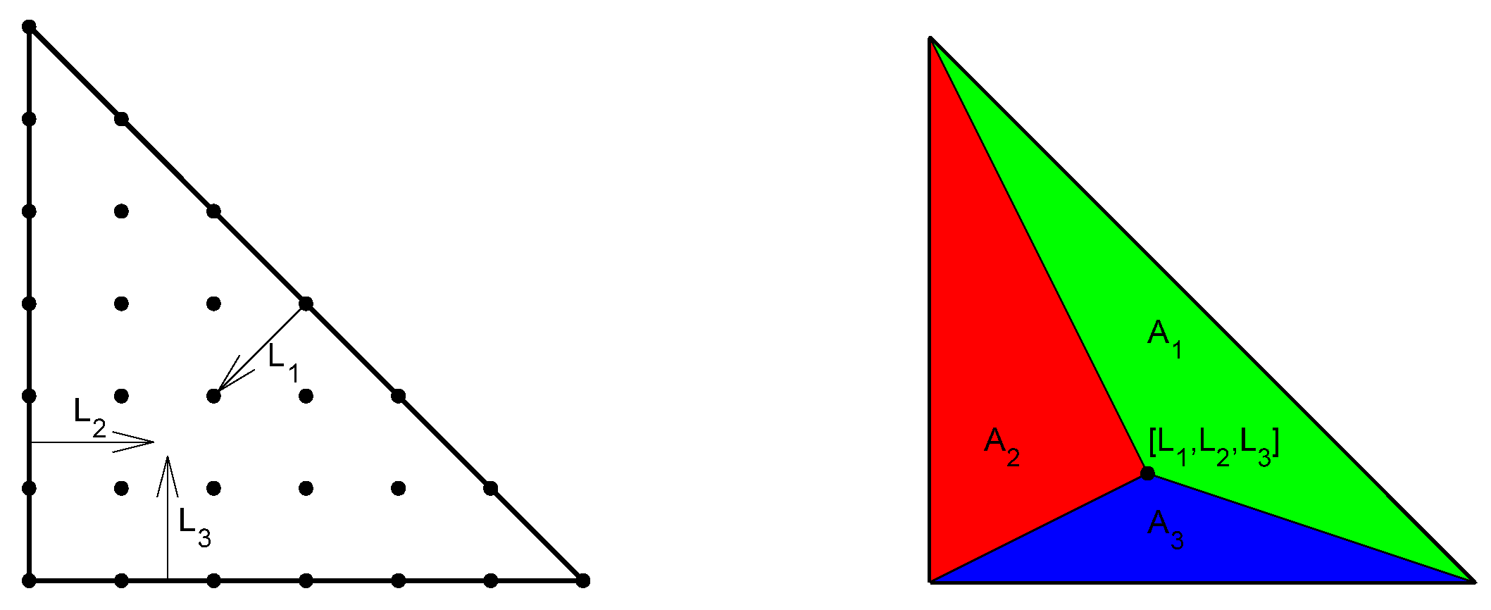
The derivation of the base functions is based on a 2D triangular 6th degree polynomial element (
Figure 8 on the left). The derivation of such a 2D element is described in [
19]. Area coordinates are used here (
Figure 8 on the right), which are defined as a proportion of the defined area to the area of the element [
20]. The first step in the algorithm is assigning the
coordinates to all nodes. Parameters
for each node are calculated from the node coordinates
where
is the degree of the element. It is now possible to express an explicit relationship for the node’s shape function
where
Functions
and
are defined analogically to function
[
19]. Parameters
determine for which node the given shape function is valid. This procedure creates a full-fledged element. The desired element does not contain any nodes. Therefore, the redundant nodes are eliminated. Redundant nodes are eliminated by dividing its shape function into proportions, which are added, in the correct ratio, to the preserved nodes.
Once the redundant nodes are eliminated, the redundant surface coordinates are converted into independent coordinates
[
20]
The resulting system of the triangular base shape functions of the derived element is as follows
The 2D triangular element is extracted into the spatial dimension by a linear shape function. The planar element exists in the
plane and its extraction is on the
axis. Two new shape functions are created from the shape function of every node. This results in a final system of 16 shape functions of the element from
Figure 7
The derived shape functions are valid in the element’s volume. The element’s volume is defined by the set,
in the space of local coordinates as
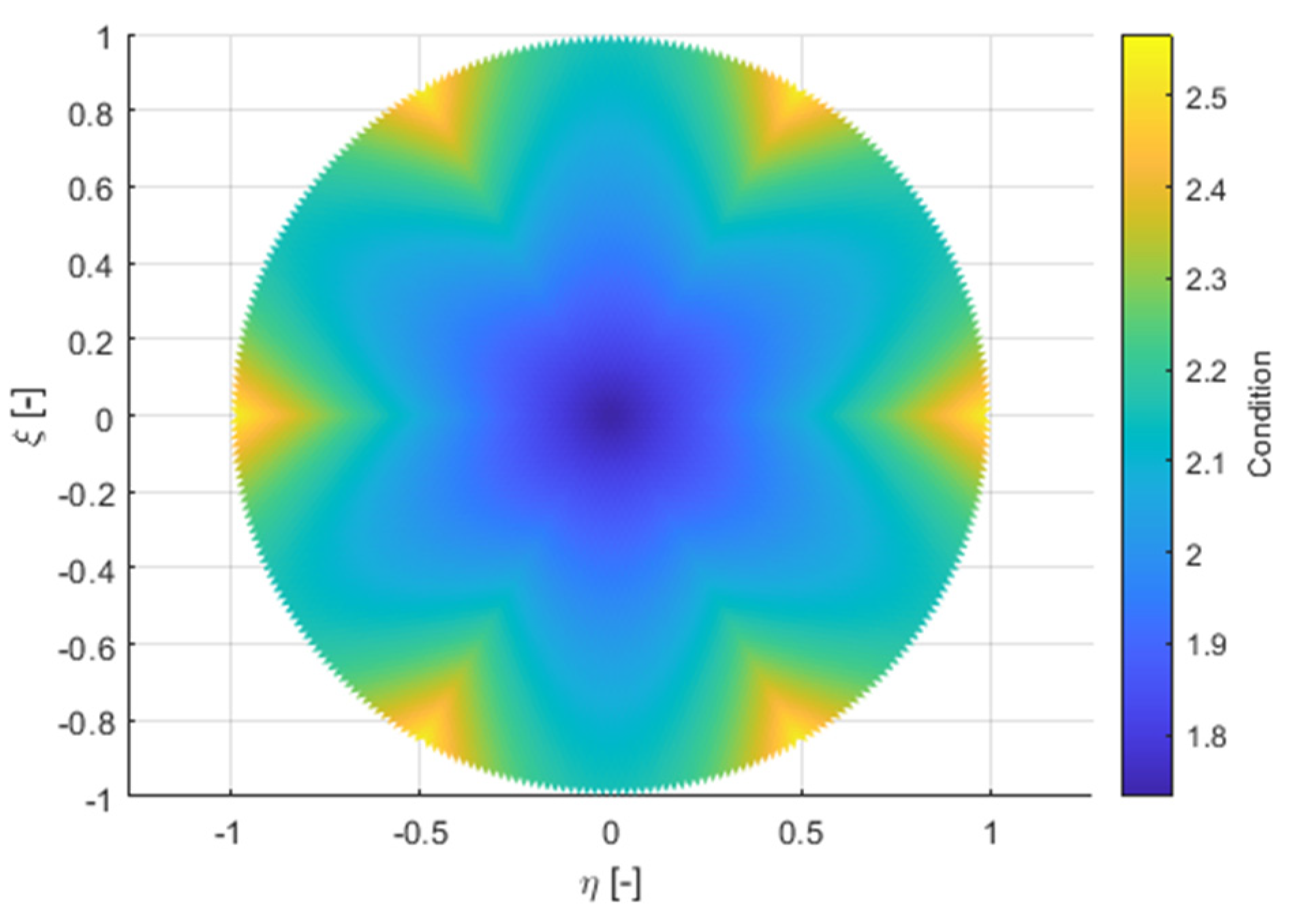
The resulting element is a polynomial of the 6th degree in a planar base and the 1st degree in the third dimension. This allows complex shapes to be modelled by only using 6 elements in every cross-section. In order for the derived element to be correct for FEM, its conditionality has to be checked in all geometric configurations, in which it is used. This was verified by numeric tests, which verified its conditionality on the tested cross-sectional shapes. Conditionality was only tested in 2D.
Figure 9 illustrates the conditionality of the elements with a circular cross-section shape. The conditionality ranges at intervals of approximately (1.7, 2.6). Ideally, the conditionality is 1 and infinite conditionality means singularity. When using numbers with a floating decimal point and 8 bytes per number, the accuracy is approximately 15 decimal places. The conditionality is proportional to the increase in the range of the matrix values during inversion and thus decreasing calculation accuracy. The conditionality values in tens are not an obstacle for the calculation.
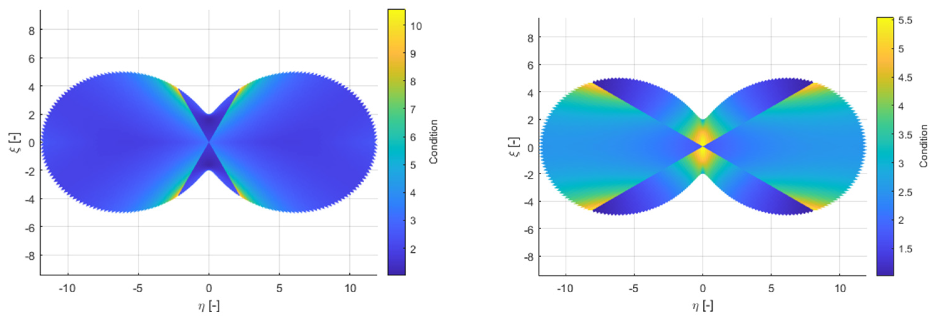
A human’s vocal tract is geometrically more complex than a rotating cylinder (circular cross-section). Therefore, a second conditionality test was conducted.
Figure 10 illustrates the test for significantly non-convex geometry. Here, it depends on how the elements are distributed in the geometry. Therefore, 2 variants are shown. The worst conditionality found is illustrated in 10.3.
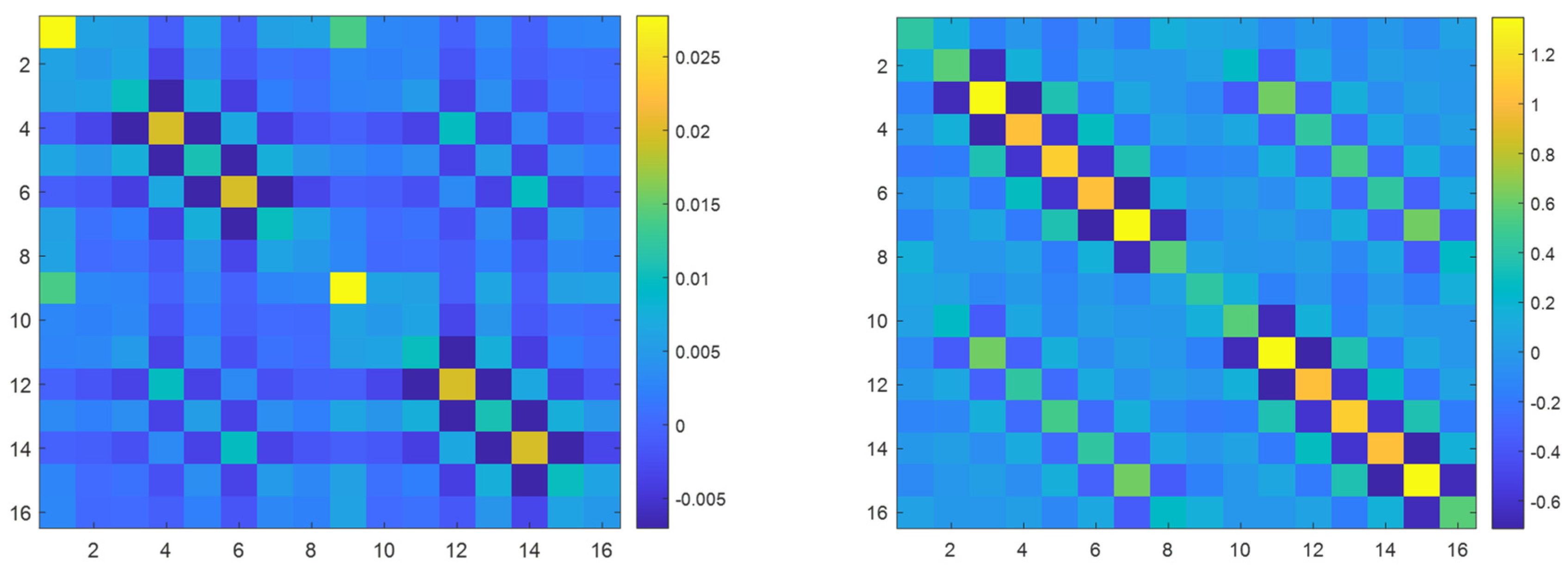
The element mass matrices and stiffness matrices for
are full. The structure of the mass and stiffness matrices are illustrated in
Figure 11. This shows that the larger values of the stiffness matrix are located in the node positions, which lies in the element’s wall, creating the VT shell. On the contrary, larger mass matrix values are found in the node positions that do not lie in this wall.
7. Properties of the Derived Isoparametric Element
Combining six derived elements results in a prismatic volume, with a node in the centre of the bases and 36 nodes along the perimeter of the bases, so 74 nodes in total. This is similar to the super-element amount created by the IRS method. Each of these groups of six elements can fill the VT volume surrounded by two cross-sections.
There is a significant difference between both types of elements. The IRS approach explicitly does not contain internal nodes, but their effect is included in the resulting super-element, while the derived isoparametric element does not contain these nodes. This results in it being able to only affect such oscillation shapes, which can be described using the existing nodes. This means that when only one group of six elements is used, it is not possible to find a higher longitudinal oscillation shape. The same problem arises with the transverse oscillation shapes. When using a sufficient number of layers assembled of a group of six derived elements, the qualitative results are the same as for the full-scale FEM models reduced by the IRS method. An advantage of the super-elements from the IRS method is the ability to find eigenfrequency of the oscillation shape, which cannot be described by the nodes used. In contrast, the model from the derived elements is incomparably numerically more effective. Assembling one group of six derived elements is direct. The shape functions are derived in general and transforming them into the necessary geometry is very easy. Therefore, creating their stiffness and mass matrices is also easy. This is done only 6x for one layer, while creating a super-element represents assembling a full FEM model from ordinary elements contains thousands of DoF. When reducing nodes, it is necessary to invert the matrix by a dimension equal to the number of reduced DoF and then invert the resulting mass matrix in every iteration. If tens of nodes are to exist after the reduction, it is then necessary to invert the matrix by thousands of rows. This is computationally demanding. Overall, assembling a model directly from derived elements is 250x more effective than simply reducing a full model, where the time it takes to assemble a full model is not taken into consideration. Moreover, if the time to assemble a new model were taken into consideration, this ratio would be even greater. This result was calculated from real computing times on a regular computer. Since it is a ratio, the same ratio can be expected on different hardware and on differently optimal codes.
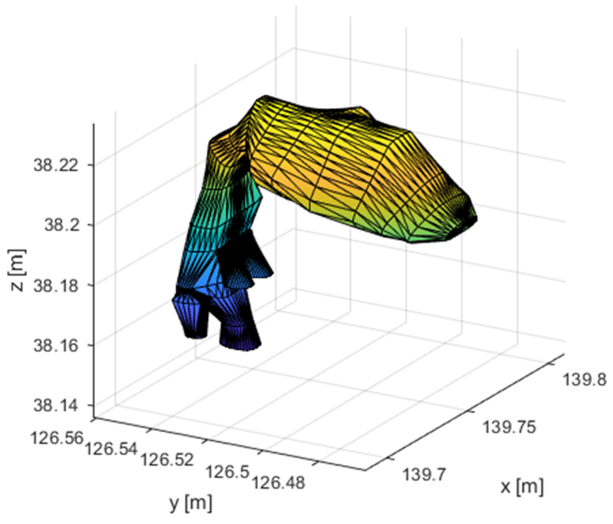
The VT model (
Figure 12) for vowel [a:], divided into parts according to
Figure 3, can be discretized by the derived isoparametric elements, using sixteen layers of elements. The VT is modelled to include parallel cavities. The piriform sinuses and the vallecula are modelled by six additional elements that are attached to the main cavity from the side. Overall, the model contains 949 nodes. There are 17 planes with nodes in the main VT cavity, which is sufficient for modelling lower longitudinal oscillation shapes, which are the most important for voice creation. The velocity of sound is chosen at 350m/s, the VT walls are assumed to be stiff. The VT is excited by speed pulses of the L-F model. It is not necessary to know the shape of these pulses to find eigenfrequencies because the boundary condition used will be of homogeneous velocity. The boundary condition at the VT output in the mouth is defined as the emitted acoustic impedance.
The model’s eigenfrequencies are illustrated in
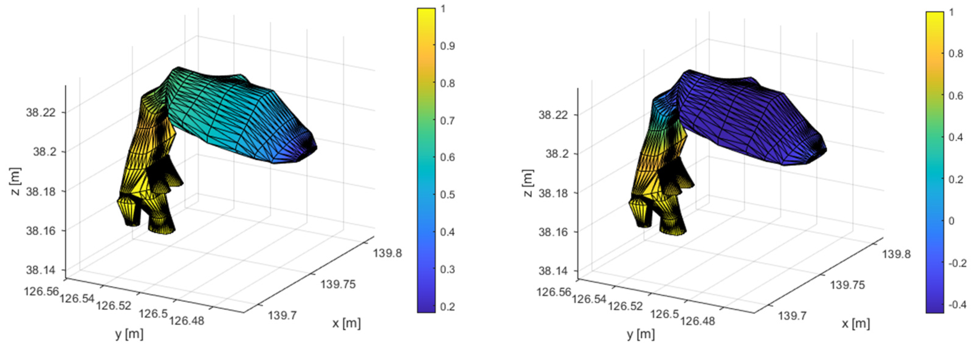
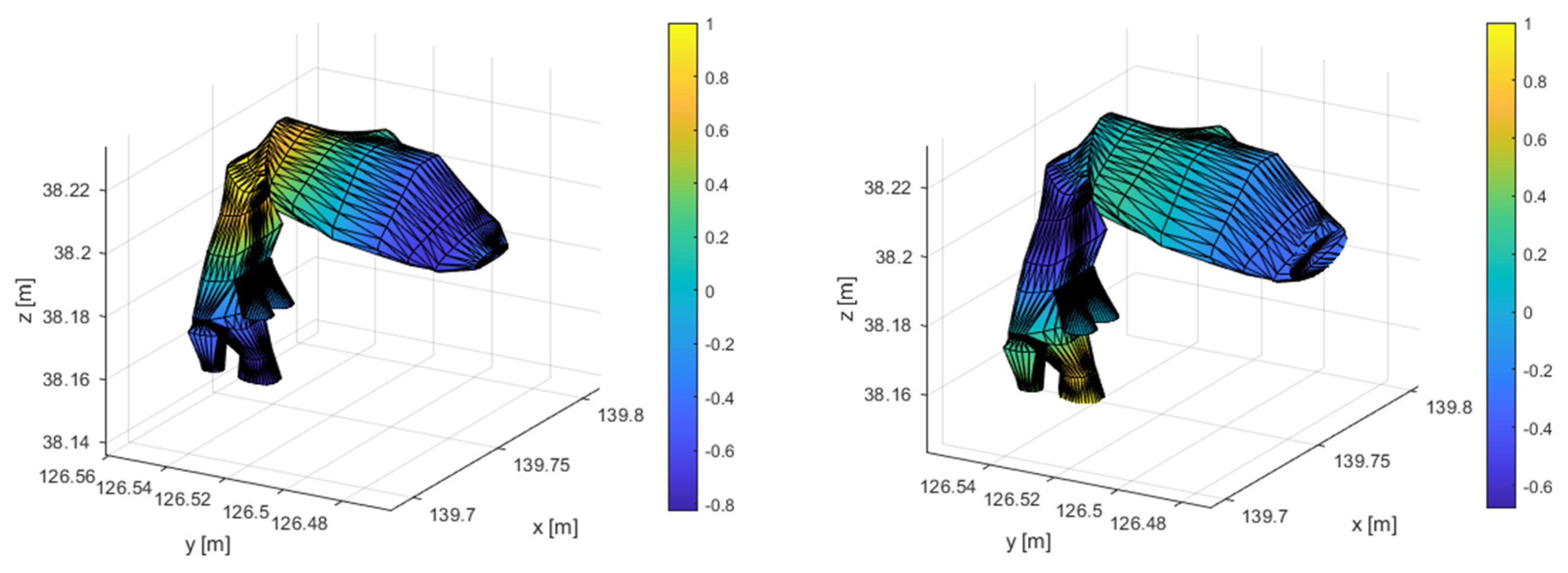
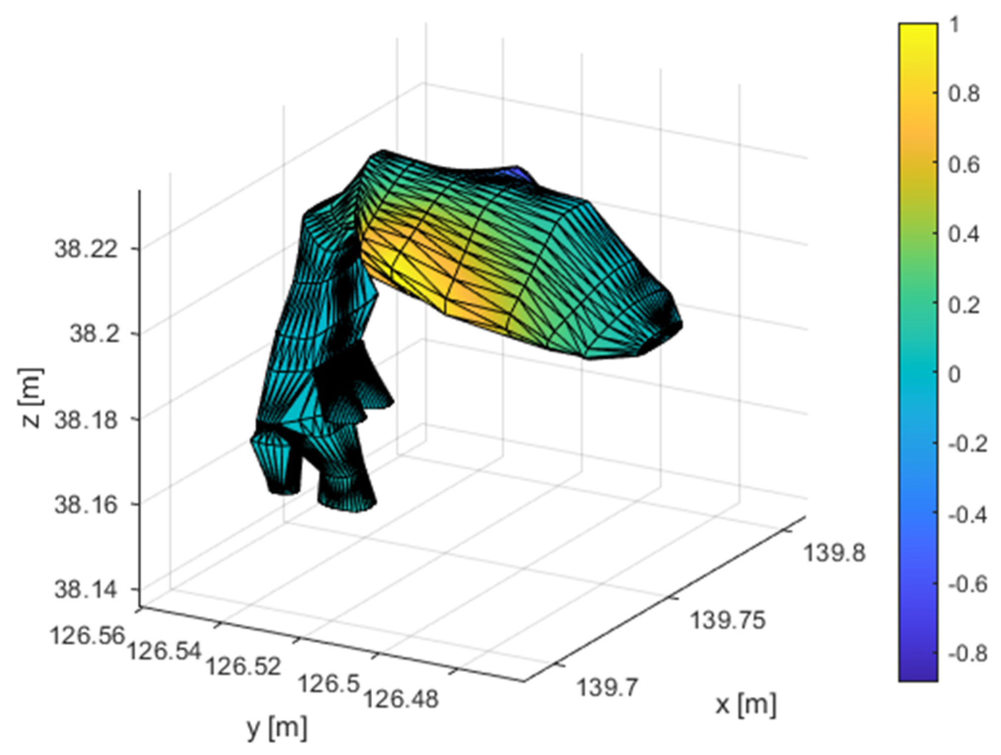
Table 1, along with a description of the respective oscillation shape. The first 4 oscillation shapes are longitudinal. The first transverse oscillation shape is in the widest part of the VT with a frequency of 4261.9Hz. For the human voice, the most significant frequency ranges between 300Hz to 5kHz. There are 5 longitudinal oscillations and one transverse oscillation in this area. The first 4 longitudinal shapes are illustrated in
Figure 13 and the first transverse shape is illustrated in
Figure 14.
.
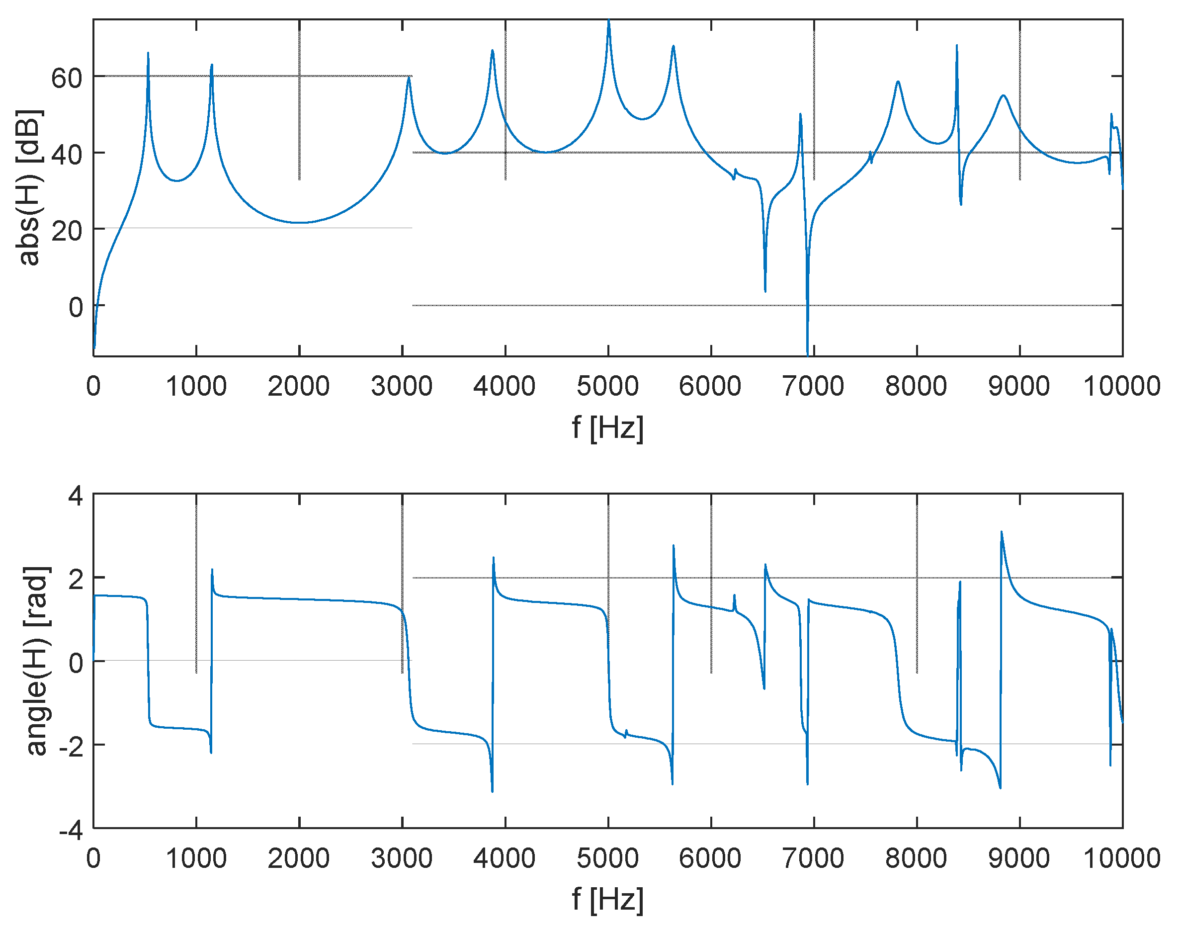
The character of the vowel is given by the formants. These are the most represented frequencies in the voice spectrum. When the VT is excited with speed pulses, the spectrum of the pulses is modulated by the VT transmission characteristic. The frequency peaks represent formants if the excitation is broadband. The transmission characteristic is in
Figure 15, which shows the significance of the character of the oscillation shape. The first 6 resonance peaks correspond to the longitudinal oscillation frequencies. There are also 2 transverse oscillations among these two shapes, which are not visible on the transmission characteristics. This is given by the position of their nodes at the excitation and emission points. Therefore, the longitudinal oscillation shapes are important for voice creation.
8. Energy Maximalization in the Frequency Band
From the viewpoint of the vocal abilities of professional singers, it’s advantageous to be able to amplify certain frequencies of the spectrum when singing. The human ear is most sensitive around 4kHz. If the singing dominantly represents frequencies around 3kHz, then this singing is much clearer and when sung with an orchestra, the orchestra does not drown out the singing. This is called a singing formant and it is primarily important for opera singers.
The singing formant is the subject of research [
21,
22]. It was found that it can be achieved by an appropriate ratio of the VT cross-section in the epiglottis and the piriform sinuses cross-section [
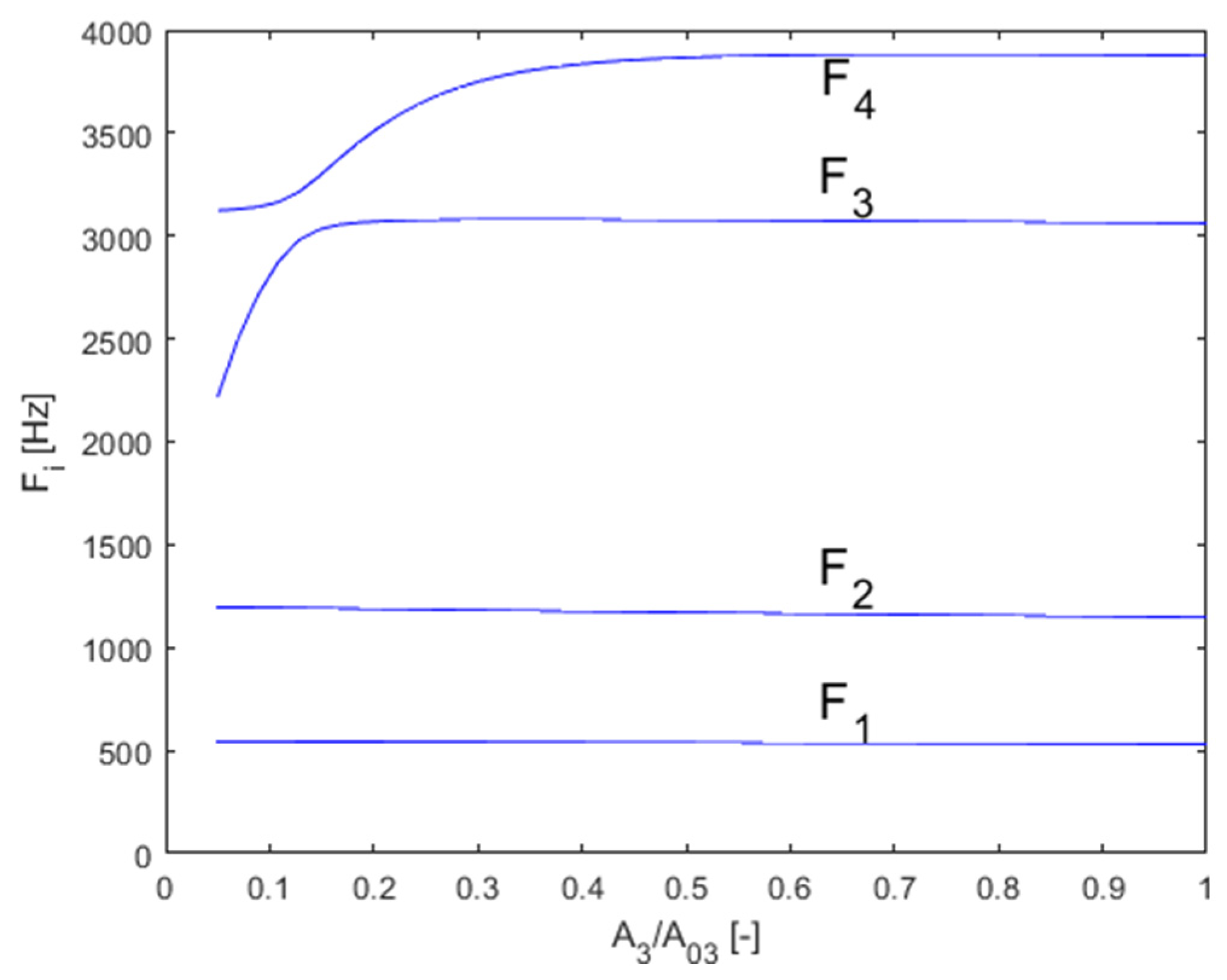
23]. Therefore, the assembled model was used to verify the hypothesis. The FEM model was parametrized to allow for changes in the cross-section of the main VT cavity in all cross-sections and the piriform sinuses cross-section. The ratio of these cross-sections was changed and the effect on the frequency of the formants was monitored (
Figure 16).
The analysis showed that given a suitable cross-section ratio, the third and fourth formants are brought closer together, to a distance of 224Hz from the original 815Hz. Bringing the two resonance peaks closer together results in a higher amplification in the transmission characteristics in
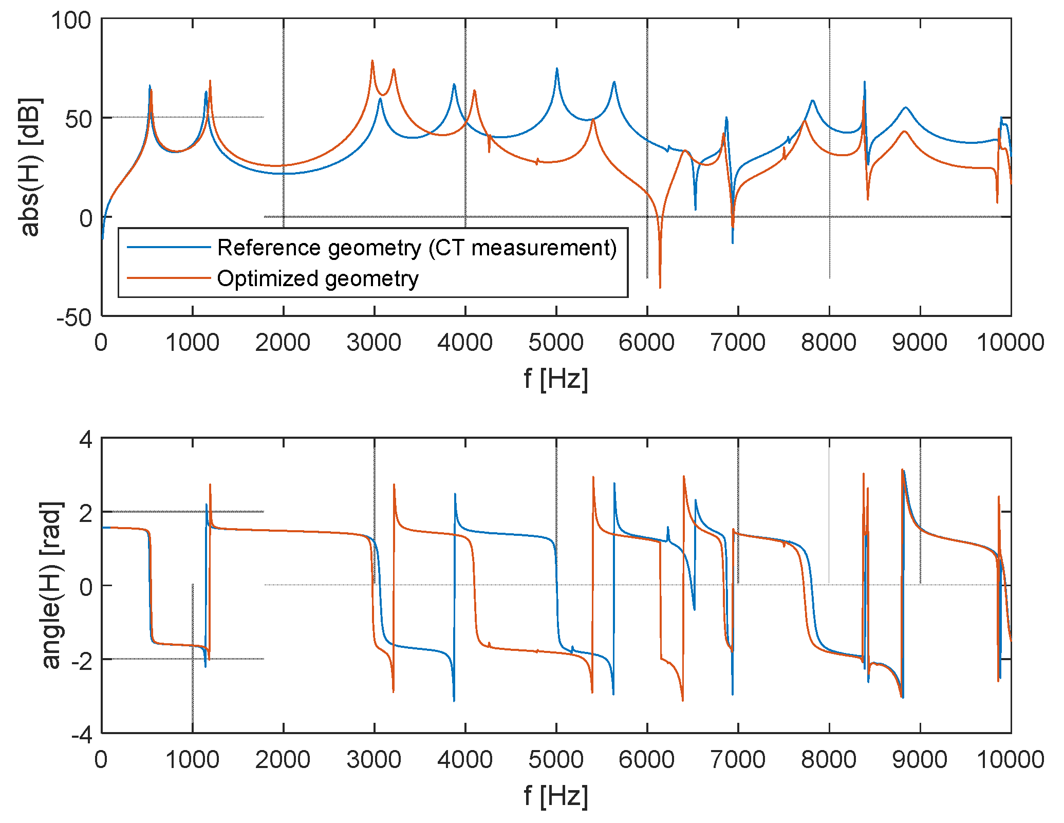
Figure 17. This can be interpreted as the singing formant. This double peak is located in the area around 3kHz, which is consistent with observations done on opera singers.
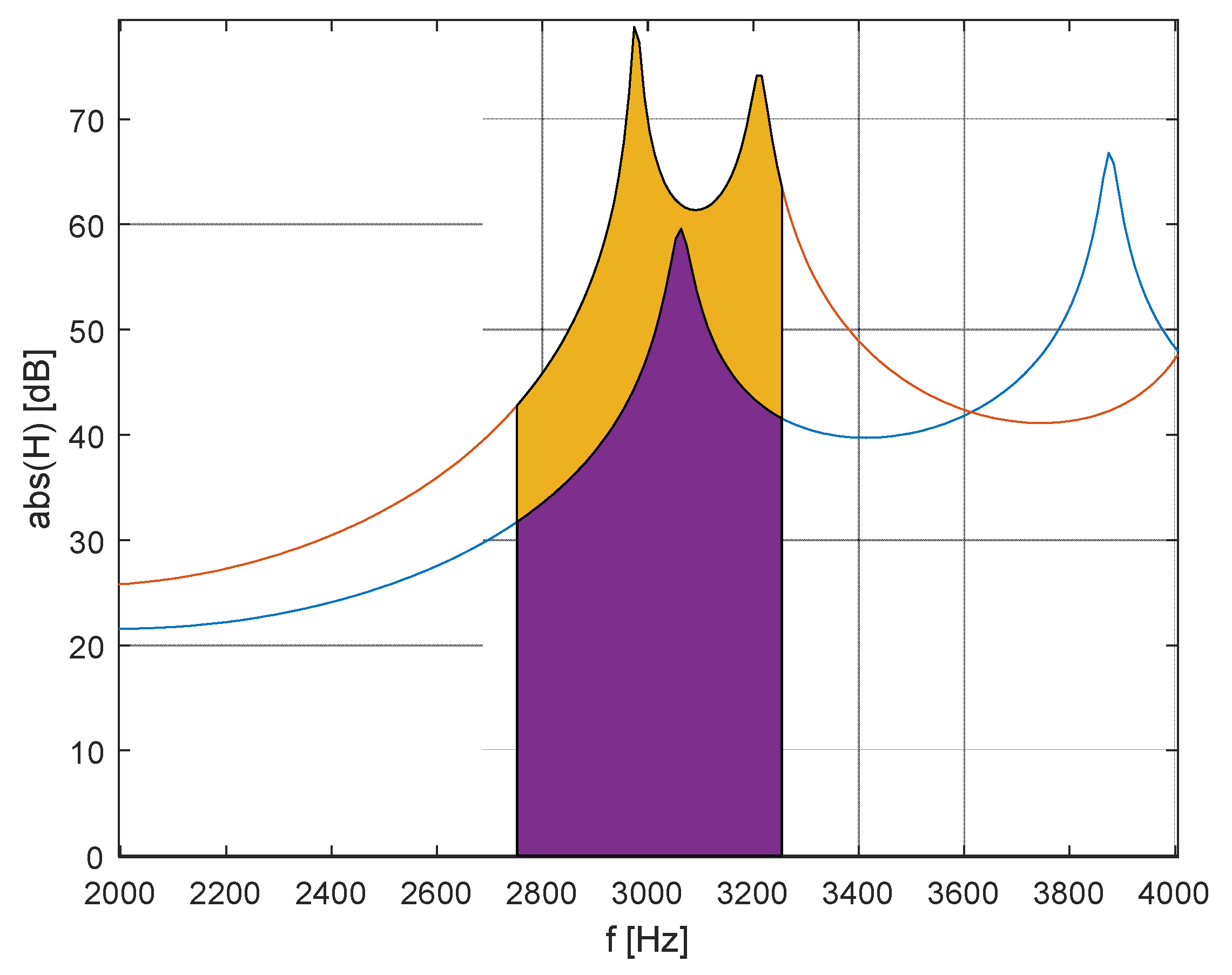
Figure 17 compares the frequency characteristics of the model modified for creating the singing formant with the original geometry model. Here, it can be seen that the geometric modification neither affected the area below 2 kHz nor the area above 7 kHz. Since it did not affect the frequency of the first 2 formants, the phonated sound did not change. The maximum amplification in the area of the singing formant (
Figure 18) increased from the original 60 dB to 79 dB, which corresponds to a ten-fold amplification. The average amplification in the 2750-3250 Hz band increased from 43 dB by 17 dB to 60 dB, which also corresponds to about a ten-fold increase in acoustic pressure.
To evaluate the amount of acoustic energy in the monitored frequency band, it is necessary to excite the transmission function. Setting up the excitation of the L-F model was selected by basic frequency pulses of 100Hz, 𝑡
𝑒 = 0.006𝑠, 𝑡
𝑎 = 0.00023𝑠, 𝑡
𝑝 = 0.0045𝑠 and 𝐸
𝑒 = 0.4 𝑚
3𝑠
−2. Acoustic energy is defined by the following relationship [
15]
Acoustic energy is made up of a potential (pressure) and a kinetic part, which changes over time. Only the pressure part of the energy is used to evaluate acoustic energy. After converting it to the frequency domain, acoustic energy is defined as follows
Exciting VT pulses generated by the vocal cords are periodic, they contain a fundamental frequency and higher harmonic components. Their spectrum is not continuous. Acoustic energy is then simply a sum of the frequency components. A comparison on the singing formant shows a 111x higher amount of energy in the monitored frequency band.
9. Conclusion
The new isoparametric element was derived for the direct assembly of FEM VT models. In parallel, a spatial FEM VT model was assembled from ordinary elements. Super-elements were created from it using the IRS method. The created VT models were compared. The aim of these procedures is to reduce the computation demands of the model. The VT geometry for vowel [a:] was obtained from CT measurements and it is very detailed. All models even include piriform sinuses and epiglottic vallecula. All of the models used achieve satisfactory compliance in terms of the results of the formant position of [a:]. However, the calculation demands vary significantly.
The FEM model created from ordinary elements has 36553 DoF and 186570 number of elements. Assembling the model requires calculating the stiffness and mass matrices for each element. This is done by numerically integrating the shape functions over a selected number of integration points. The solution then lies in analysing the resulting matrices.
The analyses of the resulting matrices can be more effective by reducing the matrices using reduction methods. In such a case, it is necessary to first assemble a full FEM model and reduce it. If the degree of reduction is high, then the largest number of demands used on the inversion of the stiffness sub-matrix takes place during the IRS procedure. In terms of size, it is close to a full matrix. Even though the IRS method reduces the DoF from 36553 to 1154, thereby decreasing the calculation demands of the formants to negligible, this saving is negatively compensated by calculating the inversion stiffness sub-matrix. As a result, this procedure is not suitable for a one-time analysis because the savings correspond to the demands for the reduction itself.
The last option used is applying a new element for FEM. The obvious advantage of this procedure is that it does not require assembling the model from ordinary elements and a calculation-efficient model is created directly, not by simplifying an extensive model. This model contains 132 elements and a 7th accuracy order integration scheme is used (4 layers with 13 integration points in a triangular plane). The total number of integration points is 6864, which is more than 100x less compared to the assembled ordinary model. The total number of DoF is 949, which represents significant savings even in assembling the global matrix since there are lower demands on the computer’s memory. When comparing the demands at the computation time level, the model assembled from the new isoparametric elements is approximately 250x faster than the simple IRS reduction. If the time needed to assemble the full FEM model were added, the ratio would be even greater.
This work compares two approaches for creating effective FEM VT models. It turns out that the generally known IRS method is less beneficial than using the new element described here. There is a considerable difference in efficiency. The model with the new element is an order of magnitude faster. One disadvantage of the new element is its design for the VT geometry. In the acoustic model, which does not geometrically resemble the VT, this element does not offer any advantages. In contrast the IRS method is applicable everywhere. The designed isoparametric element was tested by practical calculation of the singing formant. The calculation confirmed generally valid assumptions for its creation.
The model using the derived isoparametric element was used for a sensitivity study aimed at finding the optimal geometric configuration for creating a singing formant. It has been confirmed that a suitable ratio between piriform sinuses cross-section and the laryngeal part of the VT will bring the 3rd and 4th formant closer together in the area of 3kHz. This singing formant provides a 17dB higher amplification than the original model with the geometry obtained from CT measurement. The amount of acoustic energy is 111x greater than the original model when the LF model is excited by the model.
Author Contributions
Conceptualization, T.V.; methodology, J.Š.; software, J.Š.; validation, J.Š., and T.V.; formal analysis, J.Š.; investigation, T.V.; resources, J.Š.; data curation, J.Š.; writing—original draft preparation, J.Š.; writing—review and editing, T.V.; visualization, J.Š.; supervision, T.V.; project administration, T.V.; funding acquisition, T.V. All authors have read and agreed to the published version of the manuscript.
Funding
The research has been supported by the grant CTU in Prague No.930-122-5201X000 Optimizing the acoustic output with minimal possible load on the vocal cords due to changes in the human vocal tract using computer physical modeling.
Data Availability Statement
The data presented in this study are available on request from the corresponding author. The data are not publicly available due to reason non-existent infrastructure for their distribution.
Acknowledgments
The collective of authors would like to thank their colleagues for a good working environment and cooperation in the translation of this article into English.
Conflicts of Interest
The authors declare no conflict of interest. The funders had no role in the design of the study; in the collection, analyses, or interpretation of data; in the writing of the manuscript; or in the decision to publish the results.
References
- Johnson-Read, L.; Chmiel, A.; Schubert, E.; Wolfe, J. Performing Lieder: Expert Perspectives and Comparison of Vibrato and Singer’s Formant With Opera Singers. Journal of Voice 2015, 29, 645.e15–645.e32. [Google Scholar] [CrossRef] [PubMed]
- Sundberg, J. Level and Center Frequency of the Singer’s Formant. Journal of Voice 2001, 15, 176–186. [Google Scholar] [CrossRef] [PubMed]
- Arnela, M.; Dabbaghchian, S.; Blandin, R.; Guasch, O.; Engwall, O.; et al. Influence of vocal tract geometry simplifications on the numerical simulation of vowel sounds. The Journal of the Acoustical Society of America 2016, 140, 1707–1718. [Google Scholar] [CrossRef] [PubMed]
- Motoki, K. Three-dimensional acoustic field in vocal-tract. Acoustical Science and Technology 2002, 20. [Google Scholar] [CrossRef]
- Ribeiro, V.; Isaieva, K.; Leclere, J.; Vuissoz, P.; Laprie, Y. Automatic generation of the complete vocal tract shape from the sequence of phonemes to be articulated. Speech Communication 2022, 141, 1–13. [Google Scholar] [CrossRef]
- Dabbaghchian, S.; Arnela, M.; Engwall, O.; Guasch, O. Reconstruction of Vocal Tract Geometries from Biomechanical Simulations. International Journal for Numerical Methods in Biomedical Engineering 2018. [CrossRef] [PubMed]
- Kagawa, Y.; Ohtani, Y.; Shimoyama, R. Vocal tract shape identification from formant frequency spectra—A simulation using three-dimensional boundary element models. Journal of Sound and Vibration 1997, 203, 581–596. [Google Scholar] [CrossRef]
- Arnela, M.; Ureña, D. Tuned two-dimensional vocal tracts with piriform fossae for the finite element simulation of vowels. Journal of Sound and Vibration 2022, 537. [Google Scholar] [CrossRef]
- Vampola, T.; Horáček, J.; Švec, J.G. FE Modeling of Human Vocal Tract Acoustics. Part I: Production of Czech Vowels. Acta Acustica united with Acustica 2008, 94, 433–447. [Google Scholar] [CrossRef]
- Vampola, T.; Horáček, J.; Švec, J.G. Modeling the Influence of Piriform Sinuses and Valleculae on the Vocal Tract Resonances and Antiresonances. Acta Acustica united with Acustica 2015, 101, 594–602. [Google Scholar] [CrossRef]
- Vampola, T.; Laukkanen, A.M.; Horáček, J.; Švec, J.G. Vocal tract changes caused by phonation into a tube: A case study using computer tomography and finite-element modelling. The Journal of the Acoustical Society of America 2011, 129, 310–315. [Google Scholar] [CrossRef] [PubMed]
- Vampola, T.; Laukkanen, A.M.; Horáček, J.; Švec, J.G. Finite element modelling of vocal tract changes after voice therapy. Applied and Computational Mechanics 2011, 5, 77–88. [Google Scholar]
- Johnson, C. Numerical Solution of Partial Differential Equations by the Finite Element Method; Cambridge Universiry Press: Cambridge, 1987. [Google Scholar]
- Fant, G.; Liljencrants, J.; Lin, Q. A four-parameter model of glottal flow. STL-QPSR 1985, 26, 1–13. [Google Scholar]
- Pierce, S. Acoustic An introduction to Its Physical Principles and Applications; Springer, 1981; ISBN 978-3-030-11214-1. [Google Scholar]
- Guyan, R.J. Reduction of stiffness and mass matrices. American Institute of Aeronautics and Astronautics Journal 1965, 3, 380. [Google Scholar] [CrossRef]
- Blair, M.A.; Camino, T.S.; Dickens, J.M. An iterative approach to a reduced mass matrix. In Proceedings of the 8th International Modal Analysis Conference, Florence Italy, April 1991; pp. 621–626. [Google Scholar]
- Friswell, M.I.; Garvey, S.D.; Penny, J.E.T. Model reduction using dynamics and iterated IRS techniques. Journal of Sound and Vibration 1995, 186, 311–323. [Google Scholar] [CrossRef]
- Silvester, P. High-order polynomial triangular finite elements for potential problems. International Journal of Engineering Science 1969, 7, 849–861. [Google Scholar] [CrossRef]
- Bathe, K.J. Finite Elements Procedures; Prentice Hall Inc.: Upper Saddle River, New Jersey, 1996; ISBN 0-13-301458-4. [Google Scholar]
- Ikävalko, T.; Laukkanen, A.M.; Mcallister, A.; et al. Three Professional Singers’ Vocal Tract Dimensions in Operatic Singing, Kulning, and Edge—A Multiple Case Study Examining Loud Singing. Journal of Voice 2022. [Google Scholar] [CrossRef]
- Story, B. The Vocal Tract in Singing, The Oxford Handbook of Singing; Oxford Library of Psychology, 2016. [Google Scholar] [CrossRef]
- Yanagisawa, E.; Estill, J.; Kmucha, S.; Leder, S. The contribution of aryepiglottic constriction to “ringing” voice quality—A videolaryngoscopic study with acoustic analysis. Journal of Voice 1989, 3, 342–350. [Google Scholar] [CrossRef]
|
Disclaimer/Publisher’s Note: The statements, opinions and data contained in all publications are solely those of the individual author(s) and contributor(s) and not of MDPI and/or the editor(s). MDPI and/or the editor(s) disclaim responsibility for any injury to people or property resulting from any ideas, methods, instructions or products referred to in the content. |
© 2023 by the authors. Licensee MDPI, Basel, Switzerland. This article is an open access article distributed under the terms and conditions of the Creative Commons Attribution (CC BY) license (http://creativecommons.org/licenses/by/4.0/).
