Submitted:
22 September 2023
Posted:
25 September 2023
You are already at the latest version
Abstract
Keywords:
1. Introduction
2. Laboratory Structural Tests and Applications Using DIC
2.1. Concrete Beams
2.2. Columns and Pillars
2.3. Masonry Walls and Infills
2.4. Composites Materials
2.5. Structural Joints
2.6. Steel Structures
2.7. Slabs and Other Members
3. Summary of the DIC-Civil Engineering Laboratory Tests and Applications
4. Conclusions
References
- Aggelis, D. G., Verbruggen, S., Tsangouri, E., Tysmans, T., & Van Hemelrijck, D. (2013). Characterization of mechanical performance of concrete beams with external reinforcement by acoustic emission and digital image correlation. Construction and Building Materials. 47, 1037–1045. [CrossRef]
- Alam, S. Y., Loukili, A., Grondin, F., & Rozière, E. (2015). Use of the digital image correlation and acoustic emission technique to study the effect of structural size on cracking of reinforced concrete. Engineering Fracture Mechanics. 143, 17–31. [CrossRef]
- Alam, S. Y., Saliba, J., & Loukili, A. (2014). Fracture examination in concrete through combined digital image correlation and acoustic emission techniques. Construction and Building Materials. 69, 232–242. [CrossRef]
- Al-Kamaki, Y. S. S. (2021). Ultimate strain models derived using a Digital Image Correlation (DIC) system for preloaded RC columns subjected to heating and cooling and confined with CFRP sheets. Journal of Building Engineering, 41. [CrossRef]
- Allain, M. , Ple, O., Prime, N., Roux, E., & Vacher, P. (2023). In situ DIC method to determine stress state in reinforced concrete structures. Measurement: Journal of the International Measurement Confederation, 210(February 2022). [CrossRef]
- Al-Mosawe, A., Agha, H., Al-Hadeethi, L., & Al-Mahaidi, R. (2018). Efficiency of image correlation photogrammetry technique in measuring strain. Australian Journal of Structural Engineering. 19(3), 207–213. [CrossRef]
- Arora, H. , Hooper, P. A., & Dear, J. P. (2011). Dynamic response of full-scale sandwich composite structures subject to air-blast loading. Composites Part A: Applied Science and Manufacturing, 42(11), 1651–1662. [CrossRef]
- Aryanto, A., Revolis, M., Oribe, Y., & Yo, H. (2023). Application of Digital Image Correlation Method in Rc and Frc Beams Under Bending Test. International Journal of GEOMATE. 24(101), 118–125. [CrossRef]
- Bado, M. F. , Kaklauskas, G., & Casas, J. R. (2019). Performance of Distributed Optical Fiber Sensors (DOFS) and Digital Image Correlation (DIC) in the monitoring of RC structures. IOP Conference Series: Materials Science and Engineering, 615(1). [CrossRef]
- Beberniss, T. J. , & Ehrhardt, D. A. (2017). High-speed 3D digital image correlation vibration measurement: Recent advancements and noted limitations. Mechanical Systems and Signal Processing, 86, 35–48. [CrossRef]
- Becks, H., Baktheer, A., Marx, S., Classen, M., Hegger, J., & Chudoba, R. (2023). Monitoring concept for the propagation of compressive fatigue in externally prestressed concrete beams using digital image correlation and fiber optic sensors. Fatigue and Fracture of Engineering Materials and Structures. 46(2), 514–526. [CrossRef]
- Belloni, V. , Ravanelli, R., Nascetti, A., Rita, M. Di, Mattei, D., & Crespi, M. (2019). Py2dic: A new free and open source software for displacement and strain measurements in the field of experimental mechanics. Sensors (Switzerland), 19(18). [CrossRef]
- Besnard, G. , Hild, F., & Roux, S. (2006). “Finite-element” displacement fields analysis from digital images: Application to Portevin-Le Châtelier bands. Experimental Mechanics, 46(6), 789–803. [CrossRef]
- Biscaia, H. C. , Franco, N., & Chastre, C. (2018). Development of a simple bond-slip model for joints monitored with the DIC technique. Archives of Civil and Mechanical Engineering, 18(4), 1535–1546. [CrossRef]
- Blaber, J. , Adair, B., & Antoniou, A. (2015). Ncorr: Open-Source 2D Digital Image Correlation Matlab Software. Experimental Mechanics, 55(6), 1105–1122. [CrossRef]
- Bolhassani, M., Rajaram, S., Hamid, A. A., Kontsos, A., & Bartoli, I. (2016). Damage detection of concrete masonry structures by enhancing deformation measurement using DIC. Nondestructive Characterization and Monitoring of Advanced Materials, Aerospace, and Civil Infrastructure. 2016, 9804(215), 980411. [CrossRef]
- Boukhtache, S., Abdelouahab, K., Berry, F., Blaysat, B., Grédiac, M., & Sur, F. (2020). When Deep Learning Meets Digital Image Correlation. Optics and Lasers in Engineering. 136(July), 106308. [CrossRef]
- Chang, C. Y. , & Huang, C. W. (2020). Non-contact measurement of inter-story drift in three-layer RC structure under seismic vibration using digital image correlation. Mechanical Systems and Signal Processing, 136, 106500. [CrossRef]
- Chen, T. , Ye, M., Yao, C., & Xiao, Z. (2023). Fatigue behavior and digital image correlation monitoring of steel plates with mixed-mode edge cracks repaired with CFRP materials. Composite Structures, 304(P1), 116408. [CrossRef]
- Christensen, C. O. , Schmidt, J. W., Halding, P. S., Kapoor, M., & Goltermann, P. (2021). Digital image correlation for evaluation of cracks in reinforced concrete bridge slabs. Infrastructures, 6(7). [CrossRef]
- Chu, T., Peters, W. H., Ranson, W. F., & Sutton, M. A. (1982). Application of Digital Correlation Methods To Rigid Body Mechanics. Proceedings of the Society for Experimental Stress Analysis. 73–76. [CrossRef]
- Colors, M. beyond. (n.d.). MatchID 2D. www.matchidmbc.com.
- Correlated Solutions. (n.d.-a). VIC-2D. Retrieved December 23, 2022, from https://www.correlatedsolutions.com/vic-2d.
- Correlated Solutions. (n.d.-b). VIC-3D. Retrieved December 23, 2022, from https://www.correlatedsolutions.com/vic-3d.
- Daghash, S. M. , & Ozbulut, O. E. (2017). Flexural performance evaluation of NSM basalt FRP-strengthened concrete beams using digital image correlation system. Composite Structures, 176, 748–756. [CrossRef]
- Dai, Y. , & Li, H. (2022). Multi-Camera Digital Image Correlation in Deformation Measurement of Civil Components with Large Slenderness Ratio and Large Curvature. Materials, 15(18), 6281. [CrossRef]
- Dai, Y. T. , Wang, H. T., Ge, T. Y., Wu, G., Wan, J. X., Cao, S. Y., Yang, F. J., & He, X. Y. (2017). Stereo-digital image correlation in the behavior investigation of CFRP-steel composite members. Steel and Composite Structures, 23(6), 727–736. [CrossRef]
- del Rey Castillo, E. , Allen, T., Henry, R., Griffith, M., & Ingham, J. (2019). Digital image correlation (DIC) for measurement of strains and displacements in coarse, low volume-fraction FRP composites used in civil infrastructure. Composite Structures, 212, 43–57. [CrossRef]
- Demchyna, B., Surmai, M., & Tkach, R. (2019). The experimental study of glass multilayer columns using digital image correlation. Archives of Materials Science and Engineering. 96(1), 32–41. [CrossRef]
- Demchyna, B. , Surmai, M., Tkach, R., Hula, V., & Kozak, R. (2020). an Analysis of Using the Method of Two-Dimensional Digital Image Correlation in Glass Column Research. Eastern-European Journal of Enterprise Technologies, 4(12–106), 52–59. [CrossRef]
- Desai, N. (2016). Small-strain measurement in bridge connections using the digital image correlation (DIC) technique. Health Monitoring of Structural and Biological Systems. 2016, 9805(Dic), 980530. [CrossRef]
- Destrebecq, J. F., Toussaint, E., & Ferrier, E. (2011). Analysis of Cracks and Deformations in a Full Scale Reinforced Concrete Beam Using a Digital Image Correlation Technique. Experimental Mechanics. 51(6), 879–890. [CrossRef]
- Domaneschi, M. , Cimellaro, G. P., de Iuliis, M., & Marano, G. C. (2021). Laboratory investigation of digital image correlation techniques for structural assessment. Bridge Maintenance, Safety, Management, Life-Cycle Sustainability and Innovations - Proceedings of the 10th International Conference on Bridge Maintenance, Safety and Management, IABMAS 2020, 3260–3266. [CrossRef]
- Dutton, M. , Take, W. A., & Hoult, N. A. (2014). Curvature Monitoring of Beams Using Digital Image Correlation. Journal of Bridge Engineering, 19(3). [CrossRef]
- Enfedaque, A., Alberti, M. G., Gálvez, J. C., del Río, M. A., & Xiaobo, T. (2022). Use of digital image correlation to connect fracture curves and sectional analysis for structural design of polyolefin fibre reinforced concrete elements. Construction and Building Materials. 328. [CrossRef]
- Enfedaque, A., Gálvez, J. C., & Suárez, F. (2015). Analysis of fracture tests of glass fibre reinforced cement (GRC) using digital image correlation. Construction and Building Materials. 75, 472–487. [CrossRef]
- Fallah Pour, A. , Nguyen, G. D., Vincent, T., & Ozbakkaloglu, T. (2020). Investigation of the compressive behavior and failure modes of unconfined and FRP-confined concrete using digital image correlation. Composite Structures, 252(April), 112642. [CrossRef]
- Felipe-Sesé, L., Molina-Viedma, Á., López-Alba, E., & Díaz, F. (2018). Dynamic Displacements Measurement Employing Fringe Projection and Digital Image Correlation. Proceedings. 2(8), 458. [CrossRef]
- Ferreira, M. D. C. , Venturini, W. S., & Hild, F. (2011). On the analysis of notched concrete beams: From measurement with digital image correlation to identification with boundary element method of a cohesive model. Engineering Fracture Mechanics, 78(1), 71–84. [CrossRef]
- Furtado, A. , Ramos, T., Rodrigues, H., Arêde, A., Varum, H., & Tavares, P. (2015). In-plane Response of Masonry Infill Walls: Experimental Study using Digital Image Correlation. Procedia Engineering, 114(December), 870–876. [CrossRef]
- Gali, S. , & Subramaniam, K. V. L. (2017). Shear behavior of steel fiber reinforced concrete using full-field displacements from digital image correlation. MATEC Web of Conferences, 120, 1–13. [CrossRef]
- Gehri, N., Mata-Falcón, J., & Kaufmann, W. (2020). Automated crack detection and measurement based on digital image correlation. Construction and Building Materials. 256, 119383. [CrossRef]
- Gencturk, B. , Hossain, K., Kapadia, A., Labib, E., & Mo, Y. L. (2014). Use of digital image correlation technique in full-scale testing of prestressed concrete structures. Measurement: Journal of the International Measurement Confederation, 47(1), 505–515. [CrossRef]
- Ghahremannejad, M., Mahdavi, M., Saleh, A. E., Abhaee, S., & Abolmaali, A. (2018). Experimental investigation and identification of single and multiple cracks in synthetic fiber concrete beams. Case Studies in Construction Materials. 9, e00182. [CrossRef]
- Ghiassi, B., Xavier, J., Oliveira, D. v., & Lourenço, P. B. (2013). Application of digital image correlation in investigating the bond between FRP and masonry. Composite Structures. 106, 340–349. [CrossRef]
- Gholizadeh, S. (2016). A review of non-destructive testing methods of composite materials. Procedia Structural Integrity, 1, 50–57. [CrossRef]
- Ghorbani, R. , Matta, F., & Sutton, M. A. (2015). Full-Field Deformation Measurement and Crack Mapping on Confined Masonry Walls Using Digital Image Correlation. Experimental Mechanics, 55(1), 227–243. [CrossRef]
- GmbH, L. (2009). DaVis 8.2.1.
- Gorman, J. M. , & Thouless, M. D. (2019). The use of digital-image correlation to investigate the cohesive zone in a double-cantilever beam, with comparisons to numerical and analytical models. Journal of the Mechanics and Physics of Solids, 123, 315–331. [CrossRef]
- Górszczyk, J., & Malicki, K. (2019). Digital image correlation method in monitoring deformation during geogrid testing. Fibres and Textiles in Eastern Europe. 27(2), 84–90. [CrossRef]
- Guerrero, N. , Martínez, M., Picón, R., Marante, M. E., Hild, F., Roux, S., & Flórez-López, J. (2014). Experimental analysis of masonry infilled frames using digital image correlation. Materials and Structures/Materiaux et Constructions, 47(5), 873–884. [CrossRef]
- Hamrat, M., Boulekbache, B., Chemrouk, M., & Amziane, S. (2016). Flexural cracking behavior of normal strength, high strength and high strength fiber concrete beams, using Digital Image Correlation technique. Construction and Building Materials. 106, 678–692. [CrossRef]
- Helfrick, M. N. , Niezrecki, C., Avitabile, P., & Schmidt, T. (2011). 3D digital image correlation methods for full-field vibration measurement. Mechanical Systems and Signal Processing, 25(3), 917–927. [CrossRef]
- Herbert, D. M. , Gardner, D. R., Harbottle, M., Thomas, J., & Hughes, T. G. (2011). The development of a new method for testing the lateral load capacity of small-scale masonry walls using a centrifuge and digital image correlation. Construction and Building Materials, 25(12), 4465–4476. [CrossRef]
- Hossain, M. A. , Totoev, Y. Z., & Masia, M. J. (2021). Application of Digital Image Correlation (DIC) Technique for Semi Interlocking Masonry (SIM) Panels under Large Cyclic In-Plane Shear Displacement. Experimental Techniques, 45(4), 509–530. [CrossRef]
- Hou, S. , Fan, J., Wu, G., Wang, H., & Han, Y. (2021). Laboratory investigation of early damage detection for an old-aged reinforced concrete beam using acoustic emission and digital image correlation. Journal of Advanced Concrete Technology, 19(6), 700–713. [CrossRef]
- Hoult, N. A. , Dutton, M., Hoag, A., & Take, W. A. (2016). Measuring crack movement in reinforced concrete using digital image correlation: Overview and application to shear slip measurements. Proceedings of the IEEE, 104(8), 1561–1574. [CrossRef]
- Howlader, M. K. , Masia, M. J., & Griffith, M. C. (2021). Digital image correlation for the analysis of in-plane tested unreinforced masonry walls. Structures, 29, 427–445. [CrossRef]
- Janeliukstis, R. , & Chen, X. (2021). Review of digital image correlation application to large-scale composite structure testing. Composite Structures, 271(October 2020), 114143. [CrossRef]
- Kalaitzakis, M. , Kattil, S. R., Vitzilaios, N., Rizos, D., & Sutton, M. (2019). Dynamic structural health monitoring using a DIC-enabled drone. 2019 International Conference on Unmanned Aircraft Systems, ICUAS 2019, 321–327. [CrossRef]
- Kavdir, E. Ç. , & Aydin, M. D. (2019). The investigation of mechanical properties of a structural adhesive via digital image correlation (DIC) technic. Composites Part B: Engineering, 173. [CrossRef]
- Kearsley, E. , & Jacobsz, S. W. (2018). Condition assessment of reinforced concrete beams-Comparing digital image analysis with optic fibre Bragg gratings. MATEC Web of Conferences, 199. [CrossRef]
- Kim, J. H. , Lopez-Cruz, P., Heidari-Rarani, M., Lessard, L., & Laliberté, J. (2021). An experimental study on the mechanical behaviour of bonded and hybrid bonded-bolted composite joints using digital image correlation (DIC) technique. Composite Structures, 276. [CrossRef]
- Kumar, S. L., Aravind, H. B., & Hossiney, N. (2019). Digital image correlation (DIC) for measuring strain in brick masonry specimen using Ncorr open source 2D MATLAB program. Results in Engineering. 4(August), 100061. [CrossRef]
- Li, H. , Dai, Y., Qiu, H., & He, X. (2022). Application of Multi-camera Digital Image Correlation in the Stability Study of the Long Timber Column with the Circular Cross-section under Axial Compression. BioResources, 17(1), 1717–1728. [CrossRef]
- Lim, C., Jeong, Y., Limkantanyu, S., & Kwon, M. (2022). Strain Measuring of Composite Grid Using Digital Image Correlation. Advances in Materials Science and Engineering. 2022. [CrossRef]
- Luo, X., Zhang, S., Li, A., Yang, X., & Liang, Z. (2023). Steel rebar effect on tensile and cracking behavior of UHPFRC based on direct tensile tests and digital image correlation. Cement and Concrete Composites. 137(October 2022), 104940. [CrossRef]
- Mata-Falcón, J. , Haefliger, S., Lee, M., Galkovski, T., & Gehri, N. (2020). Combined application of distributed fibre optical and digital image correlation measurements to structural concrete experiments. Engineering Structures, 225(December 2019). [CrossRef]
- Mehdi Mirzazadeh, M. , & Green, M. F. (2018). Fiber Optic Sensors and Digital Image Correlation for Measuring Deformations in Reinforced Concrete Beams. Journal of Bridge Engineering, 23(3). [CrossRef]
- Metrology, P. I. 3D. (2019). GOM Correlate. https://www.gom.com/3d-software/gom-correlate.html.
- Miikki, K. , Karakoç, A., Rafiee, M., Lee, D. W., Vapaavuori, J., Tersteegen, J., Lemetti, L., & Paltakari, J. (2021). An open-source camera system for experimental measurements. SoftwareX, 14, 100688. [CrossRef]
- Mojsilović, N. , & Salmanpour, A. H. (2016). Masonry walls subjected to in-plane cyclic loading: Application of digital image correlation for deformation field measurement. International Journal of Masonry Research and Innovation, 1(2), 165–187. [CrossRef]
- Mousa, M. A. , & Yussof, M. M. (2021). A simple two-dimensional digital image correlation model for out of plane displacement using smartphone camera. Journal of Engineering Science and Technology, 16, 10–17.
- Mousa, M. A. , Yussof, M. M., Assi, L. N., & Ghahari, S. A. (2022). A Pre-Process Enhanced Digital Image Correlation Approach for Smart Structure Monitoring. Infrastructures, 7(10). [CrossRef]
- Mousa, M. A., Yussof, M. M., Ruii, C. Z., Nazri, F. M., & Kamarudin, M. K. (2021). Prediction of crack path on concrete prism based on strain field using image analysis technique. Malaysian Construction Research Journal. 14(3 Special issue), 85–97.
- Murali Krishna, B. , Tezeswi, T. P., Rathish Kumar, P., Gopikrishna, K., Sivakumar, M. V. N., & Shashi, M. (2019). QR code as speckle pattern for reinforced concrete beams using digital image correlation. Structural Monitoring and Maintenance, 6(1), 67–84. [CrossRef]
- Ngeljaratan, L. , & Moustafa, M. A. (2017). Digital image correlation for dynamic shake table test measurements. International Conference on Advances in Experimental Structural Engineering, 2017-Septe(July), 741–752. [CrossRef]
- Ngeljaratan, L. , & Moustafa, M. A. (2019). System identification of large-scale bridges using target-tracking digital image correlation. Frontiers in Built Environment, 5(June). [CrossRef]
- Nghiem, H. L., Al Heib, M., & Emeriault, F. (2015). Method based on digital image correlation for damage assessment in masonry structures. Engineering Structures. 86, 1–15. [CrossRef]
- Nova Instruments. (2016). Istra4D software manual Q-400 system, dantec dynamics, (version 4.4.5). Nova Instruments Company.
- Olufsen, S. N. , Andersen, M. E., & Fagerholt, E. (2020). μDIC: An open-source toolkit for digital image correlation. SoftwareX, 11. [CrossRef]
- Omondi, B., Aggelis, D. G., Sol, H., & Sitters, C. (2016). Improved crack monitoring in structural concrete by combined acoustic emission and digital image correlation techniques. Structural Health Monitoring. 15(3), 359–378. [CrossRef]
- Padmappriya, S., & Sumalatha, K. (2018). Digital Image Processing Real Time Applications. International Journal of Engineering Science Invention. 46–51.
- Paliwal, I. , & Ramji, M. (2022). A detailed study on the damage evolution and failure assessment of single-lap hybrid joints in CFRP laminates under tensile loading. Composite Structures, 299(July), 116021. [CrossRef]
- Pan, B. , & Tian, L. (2016). Advanced video extensometer for non-contact, real-time, high-accuracy strain measurement. Optics Express. [CrossRef]
- Pan, B. , Tian, L., & Song, X. (2016). Real-time, non-contact and targetless measurement of vertical deflection of bridges using off-axis digital image correlation. NDT and E International, 79, 73–80. [CrossRef]
- Pan, B. , Yu, L., & Wu, D. (2014). High-accuracy 2D digital image correlation measurements using low-cost imaging lenses: Implementation of a generalized compensation method. Measurement Science and Technology, 25(2). [CrossRef]
- Peddle, J., Goudreau, A., Carlson, E., & Santini-Bell, E. (2011). Bridge displacement measurement through digital image correlation. Bridge Structures. 7(4), 165–173. [CrossRef]
- Peng, Y., Wu, C., Gan, J., & Dong, J. (2018). Determination of the local constitutive properties of the welded steel joints using digital image correlation method. Construction and Building Materials. 171, 485–492. [CrossRef]
- Peters, W. H., & Ranson, W. F. (1982). Digital imaging techniques in experimental stress analysis. Optical Engineering. 21(3), 427–431.
- Pierrot-Deseilligny, M. , & Paparoditis, N. (2006). A multiresolution and optimization-based image matching approach: An application to surface reconstruction from SPOT5-HRS stereo imagery. International Archives of …, XXXVI, 1–5. http://www.micmac.ign.fr/svn/micmac/tags/1.0.0/Documentation/DocMicMac/ankara2006-pierrot.pdf.
- Pisonero, J. , Lopez-Rebollo, J., Garcia-Martin, R., Rodriguez-Martin, M., Sanchez-Aparicio, L. J., Munoz-Nieto, A., & Gonzalez-Aguilera, Di. (2017). A Comparative Study of 2D and 3D Digital Image Correlation Approaches for the Characterization and Numerical Analysis of Composite Materials. IEEE Access, 9(Dic), 160675–160687. [CrossRef]
- PMLAB. (2014). Digital Image Correlation Software PMLAB DIC-3D_2014a. Nanjing PMLAB*Sensor Tech. Co., Ltd. http://www.pmlab.com.cn.
- Pohoryles, D. A. , Melo, J., Rossetto, T., Fabian, M., McCague, C., Stavrianaki, K., Lishman, B., & Sargeant, B. (2017). Use of DIC and AE for Monitoring Effective Strain and Debonding in FRP and FRCM-Retrofitted RC Beams. Journal of Composites for Construction, 21(1), 1–11. [CrossRef]
- Ramos, T. , Furtado, A., Eslami, S., Alves, S., Rodrigues, H., Arêde, A., Tavares, P. J., & Moreira, P. M. G. P. (2015). 2D and 3D Digital Image Correlation in Civil Engineering - Measurements in a Masonry Wall. Procedia Engineering, 114(December), 215–222. [CrossRef]
- Rouchier, S., Foray, G., Godin, N., Woloszyn, M., & Roux, J. J. (2013). Damage monitoring in fibre reinforced mortar by combined digital image correlation and acoustic emission. Construction and Building Materials. 38, 371–380. [CrossRef]
- Ruocci, G. , Rospars, C., Moreau, G., Bisch, P., Erlicher, S., Delaplace, A., & Henault, J. M. (2016). Digital Image Correlation and Noise-filtering Approach for the Cracking Assessment of Massive Reinforced Concrete Structures. Strain, 52(6), 503–521. [CrossRef]
- Salmanpour, A. H. , & Mojsilović, N. (2013). Application of Digital Image Correlation for strain measurements of large masonry walls. In: Proceedings of the 5th Asia Pacific Congress on Computational Mechanics, December 2013, Paper no. 1128. http://www.sci-en-tech.com/apcom2013/APCOM2013-Proceedings/PDF_FullPaper/1128.pdf.
- Sharafisafa, M. , Aliabadian, Z., & Shen, L. (2020). Crack initiation and failure of block-in-matrix rocks under Brazilian test using digital image correlation. Theoretical and Applied Fracture Mechanics, 109(July). [CrossRef]
- Shih, M. H., & Sung, W. P. (2014). Developing dynamic digital image correlation technique to monitor structural damage of old buildings under external excitation. Shock and Vibration. 2014. [CrossRef]
- Shih, M. H. , Sung, W. P., & Tsai, F. J. (2011). Analysis accuracy of digital image correlation technique to monitor natural frequency response of building under dynamic excitation. Applied Mechanics and Materials, 71–78, 3904–3908. [CrossRef]
- Shih, M., & Sung, W. (2014). Developing Dynamic Digital Image Correlation Technique to Monitor Structural Damage of Old Buildings under External Excitation. Shock and Vibration. 2014.
- Shuai, J., Zhao, J., & Lei, L. (2022). Simple crack tip and stress intensity factor determination method for model I crack using digital image correlation. Theoretical and Applied Fracture Mechanics. 122(September), 103621. [CrossRef]
- Słoński, M. , & Tekieli, M. (2020). 2D digital image correlation and region-based convolutional neural network in monitoring and evaluation of surface cracks in concrete structural elements. Materials, 13(16). [CrossRef]
- Smith, B. J., Kurama, Y. C., & McGinnis, M. J. (2011). Design and Measured Behavior of a Hybrid Precast Concrete Wall Specimen for Seismic Regions. Journal of Structural Engineering. 137(10), 1052–1062. [CrossRef]
- Solav, D. , Moerman, K. M., Jaeger, A. M., Genovese, K., & Herr, H. M. (2018). MultiDIC: An open-source toolbox for multi-view 3D digital image correlation. IEEE Access, 6, 30520–30535. [CrossRef]
- Solutions, C. (2017). Vic-2D Software.
- Sousa, J. B., Garcia, S. L. G., & Pierott, R. M. R. (2023). Shear Behavior of Recycled Coarse Aggregates Concrete Dry Joints Keys Using Digital Image Correlation Technique. Infrastructures. 8(3), 1–24. [CrossRef]
- Sozen, S., & Guler, M. (2011). Determination of displacement distributions in bolted steel tension elements using digital image techniques. Optics and Lasers in Engineering. 49(12), 1428–1435. [CrossRef]
- Spencer, R. , Hassen, A. A., Baba, J., Lindahl, J., Love, L., Kunc, V., Babu, S., & Vaidya, U. (2021). An innovative digital image correlation technique for in-situ process monitoring of composite structures in large scale additive manufacturing. Composite Structures, 276(March), 114545. [CrossRef]
- Stanier, S. A. , Blaber, J., Take, W. A., & White, D. J. (2016). Improved image-based deformation measurement for geotechnical applications. Canadian Geotechnical Journal, 53(5), 727–739. [CrossRef]
- Sun, F. , & Blackman, B. R. K. (2020). A DIC method to determine the Mode I energy release rate G, the J - integral and the traction-separation law simultaneously for adhesive joints. Engineering Fracture Mechanics, December 2019, 107097. [CrossRef]
- Sun, Z. , Zheng, Y., Sun, Y., Shao, X., & Wu, G. (2023). Deformation ability of precast concrete columns reinforced with steel-FRP composite bars (SFCBs) based on the DIC method. Journal of Building Engineering, 68(September 2022), 106083. [CrossRef]
- Suryanto, B. , Tambusay, A., & Suprobo, P. (2017). Crack Mapping on Shear-critical Reinforced Concrete Beams using an Open Source Digital Image Correlation Software. Civil Engineering Dimension, 19(2), 93–98. [CrossRef]
- Take, W. A. (2015). Thirty-Sixth Canadian Geotechnical Colloquium: Advances in visualization of geotechnical processes through digital image correlation. Canadian Geotechnical Journal, 52(9), 1199–1220. [CrossRef]
- Tehrani, A. D. , Kouchesfehani, Z. K., & Najafi, M. (2020). Pipe Profiling Using Digital Image Correlation. Pipelines 2020: Condition Assessment, Construction, Rehabilitation, and Trenchless Technologies - Proceedings of Sessions of the Pipelines 2020 Conference, 36–45. [CrossRef]
- Tekieli, M., De Santis, S., de Felice, G., Kwiecień, A., & Roscini, F. (2017). Application of Digital Image Correlation to composite reinforcements testing. Composite Structures. 160, 670–688. [CrossRef]
- Tekieli, M. , & Słoński, M. (2013). Application of Monte Carlo Filter for Computer Vision-Based Bayesian Updating of Finite Element Model. Mechanics and Control, 32(4), 171. [CrossRef]
- The Math Works, Inc. (2020). MATLAB (R2020b).
- Thériault, F., Noël, M., & Sanchez, L. (2022). Simplified approach for quantitative inspections of concrete structures using digital image correlation. Engineering Structures. 252(November 2021), 1–12. [CrossRef]
- Tian, L. , Yu, L., & Pan, B. (2018). Accuracy enhancement of a video extensometer by real-time error compensation. Optics and Lasers in Engineering. [CrossRef]
- Tian, L. , Zhang, X., & Pan, B. (2021). Cost-Effective and Ultraportable Smartphone-Based Vision System for Structural Deflection Monitoring. Journal of Sensors, 2021. [CrossRef]
- Tian, L. , Zhao, J., Pan, B., & Wang, Z. (2021). Full-field bridge deflection monitoring with off-axis digital image correlation. Sensors, 21(15), 4664–4672. [CrossRef]
- Torres, B. , Varona, F. B., Baeza, F. J., Bru, D., & Ivorra, S. (2020). Study on retrofitted masonry elements under shear using digital image correlation. Sensors (Switzerland), 20(7). [CrossRef]
- Tsangouri, E. , Aggelis, D. G., Van Tittelboom, K., De Belie, N., & Van Hemelrijck, D. (2013). Detecting the activation of a self-healing mechanism in concrete by acoustic emission and digital image correlation. The Scientific World Journal, 2013. [CrossRef]
- Tung, S. H. , Shih, M. H., & Sung, W. P. (2008). Development of digital image correlation method to analyse crack variations of masonry wall. Sadhana - Academy Proceedings in Engineering Sciences, 33(6), 767–779. [CrossRef]
- Tung, S. H. , Shih, M. H., & Sung, W. P. (2014). Applying the digital-image-correlation technique to measure the deformation of an old building’s column retrofitted with steel plate in an in situ pushover test. Sadhana - Academy Proceedings in Engineering Sciences, 39(3), 699–711. [CrossRef]
- Vacher, P. , Dumoulin, S., Morestin, F., & Mguil-Touchal, S. (1999). Bidimensional strain measurement using digital images. Proceedings of the Institution of Mechanical Engineers, Part C: Journal of Mechanical Engineering, 213(8), 811–817. [CrossRef]
- Wang, N., Ri, K., Liu, H., & Zhao, X. (2018a). Structural displacement monitoring using smartphone camera and digital image correlation. IEEE Sensors Journal. 18(11), 4664–4672. [CrossRef]
- Wang, N., Ri, K., Liu, H., & Zhao, X. (2018b). Structural displacement monitoring using smartphone camera and digital image correlation. IEEE Sensors Journal. 18(11), 4664–4672. [CrossRef]
- Wani, Z. R. , Tantray, M., & Noroozinejad Farsangi, E. (2022). In-Plane measurements using a novel streamed digital image correlation for shake table test of steel structures controlled with MR dampers. Engineering Structures, 256(May 2021), 113998. [CrossRef]
- White, D. J., Take, W. A., & Bolton, M. D. (2003). Soil deformation measurement using particle image velocimetry (PIV) and photogrammetry. Geotechnique. 53(7), 619–631. [CrossRef]
- Winkler, J. , Specialist, C., & Hansen, M. D. (2018). Innovative long-term monitoring of the great belt bridge expansion joint using digital image correlation. Structural Engineering International, 28(3), 347–352. [CrossRef]
- Wittevrongel, L., Badaloni, M., Balcaen, R., Lava, P., & Debruyne, D. (2015). Evaluation of Methodologies for Compensation of Out of Plane Motions in a 2D Digital Image Correlation Setup. Strain. 357–369. [CrossRef]
- Xie, X. , Guo, Z.-X., & Basha, S. H. (2023). Out-of-Plane behavior of clay brick masonry infills contained within RC frames using 3D-Digital image correlation technique. Construction and Building Materials, 376(October 2022), 131061. [CrossRef]
- Xu, P. , Zhou, Z., Liu, T., Pan, S., & Tan, X. (2022). In-situ damage assessment of FML joints under uniaxial tension combining with acoustic emission and DIC: Geometric influence on damage formation. Thin-Walled Structures, 170(October 2021), 108515. [CrossRef]
- Yoneyama, S., & Ueda, H. (2012). Bridge deflection measurement using digital image correlation with camera movement correction. Materials Transactions. 53(2), 285–290. [CrossRef]
- Yu, L. , Bekdullayev, N., & Lubineau, G. (2021). Smartphone-Based Single-Camera Stereo-DIC System: Thermal Error Analysis and Design Recommendations. IEEE Sensors Journal, 21(7), 9567–9576. [CrossRef]
- Yu, L. , & Lubineau, G. (2021). A smartphone camera and built-in gyroscope based application for non-contact yet accurate off-axis structural displacement measurements. Measurement: Journal of the International Measurement Confederation, 167. [CrossRef]
- Yu, L. , Tao, R., & Lubineau, G. (2019). Accurate 3D shape, displacement and deformation measurement using a Smartphone. Sensors (Switzerland), 19(3). [CrossRef]
- Yu, Q.-Q. , & Wu, Y.-F. (2017). Fatigue Strengthening of Cracked Steel Beams with Different Configurations and Materials. Journal of Composites for Construction, 21(2). [CrossRef]
- Zhang, N. , Hedayat, A., Bolaños Sosa, H. G., Tunnah, J., González Cárdenas, J. J., & Salas Álvarez, G. E. (2021). Estimation of the mode I fracture toughness and evaluations on the strain behaviors of the compacted mine tailings from full-field displacement fields via digital image correlation. Theoretical and Applied Fracture Mechanics, 114(March). [CrossRef]
- Zhou, K. , Lei, D., He, J., Zhang, P., Bai, P., & Zhu, F. (2021). Real-time localization of micro-damage in concrete beams using DIC technology and wavelet packet analysis. Cement and Concrete Composites, 123. [CrossRef]
- Ziaja, D. , Turoń, B., & Miller, B. (2020). Detection of anomaly in a pretensioned bolted beam-to-column connection node using digital image correlation and neural networks. Applied Sciences (Switzerland), 10(7). [CrossRef]
- Zona, A. (2021). Vision-based vibration monitoring of structures and infrastructures: An overview of recent applications. Infrastructures, 6(1), 1–22. [CrossRef]
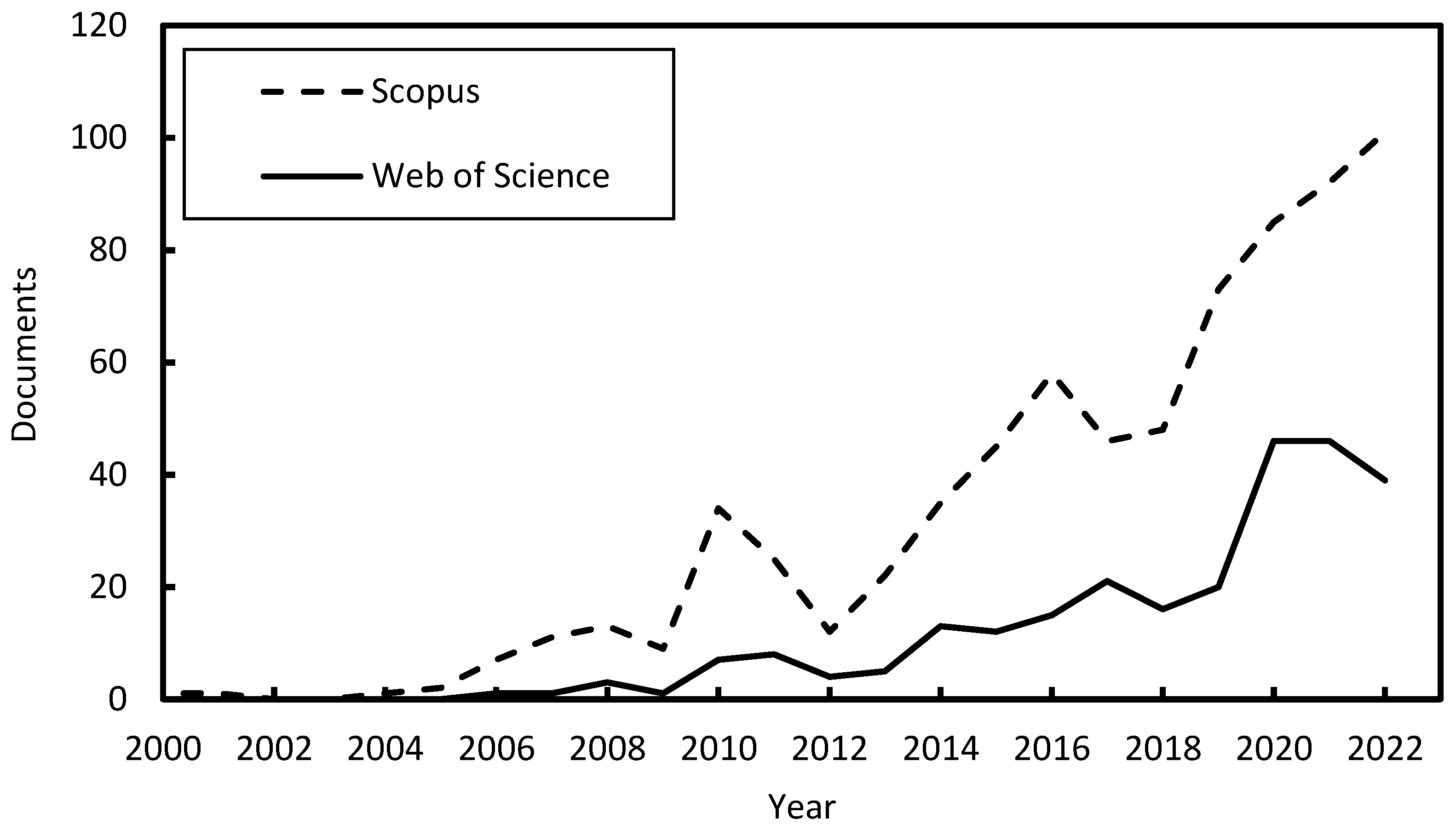
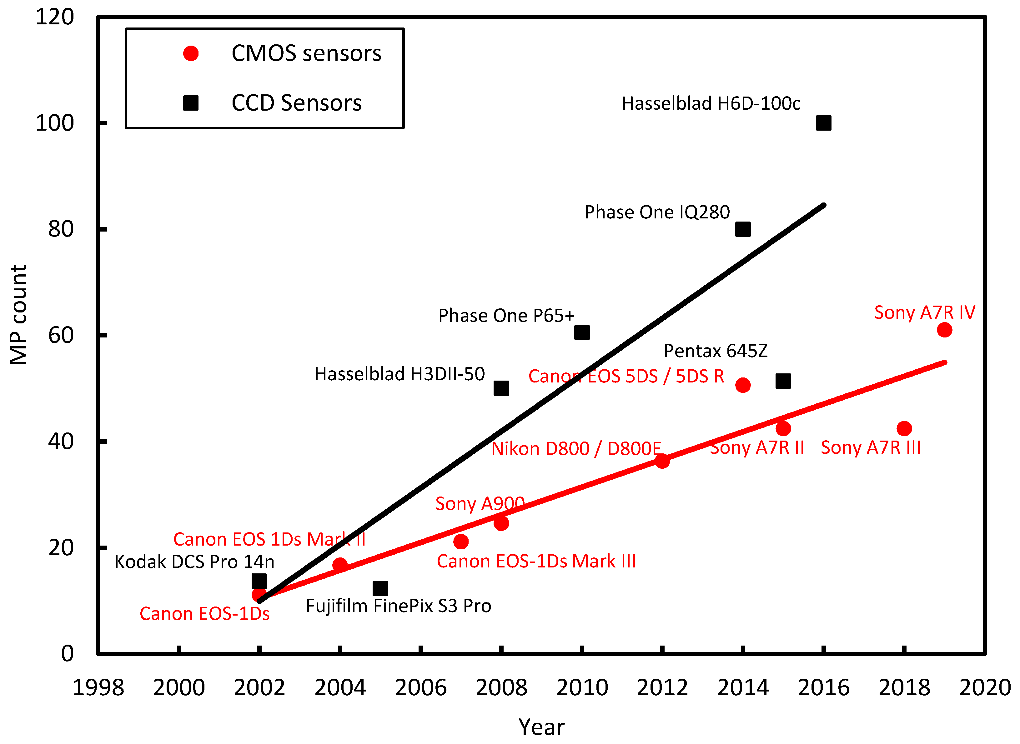
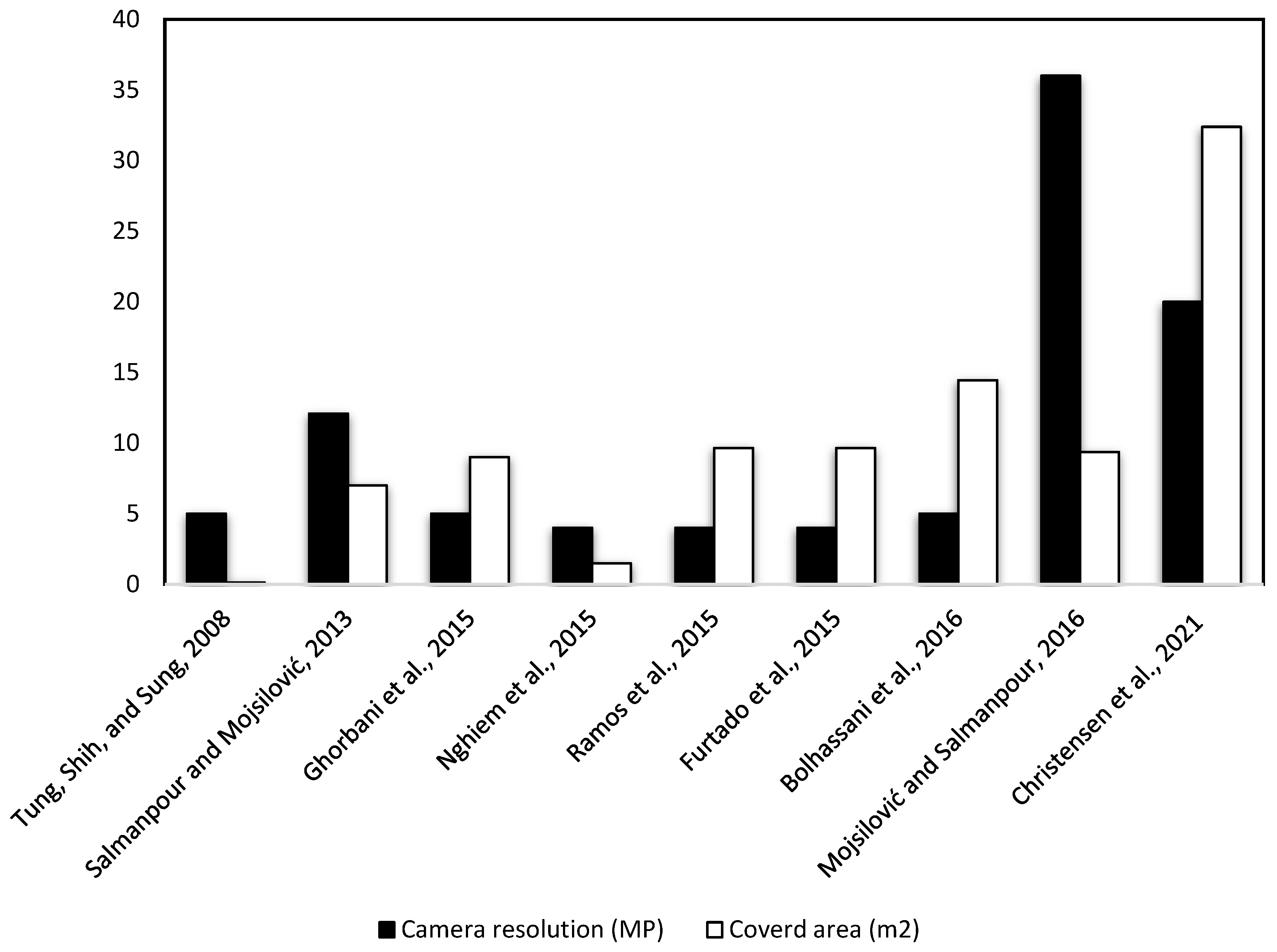
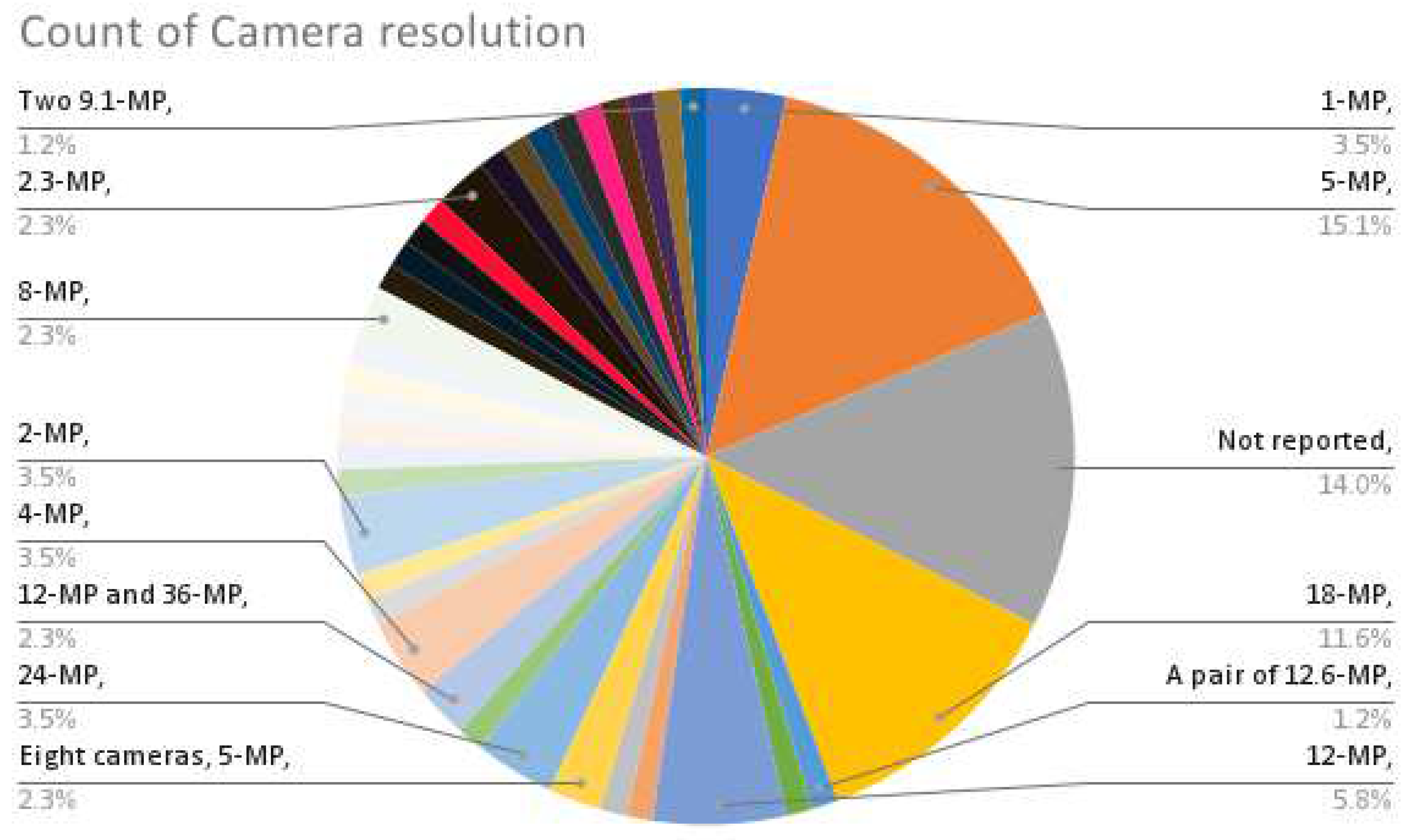

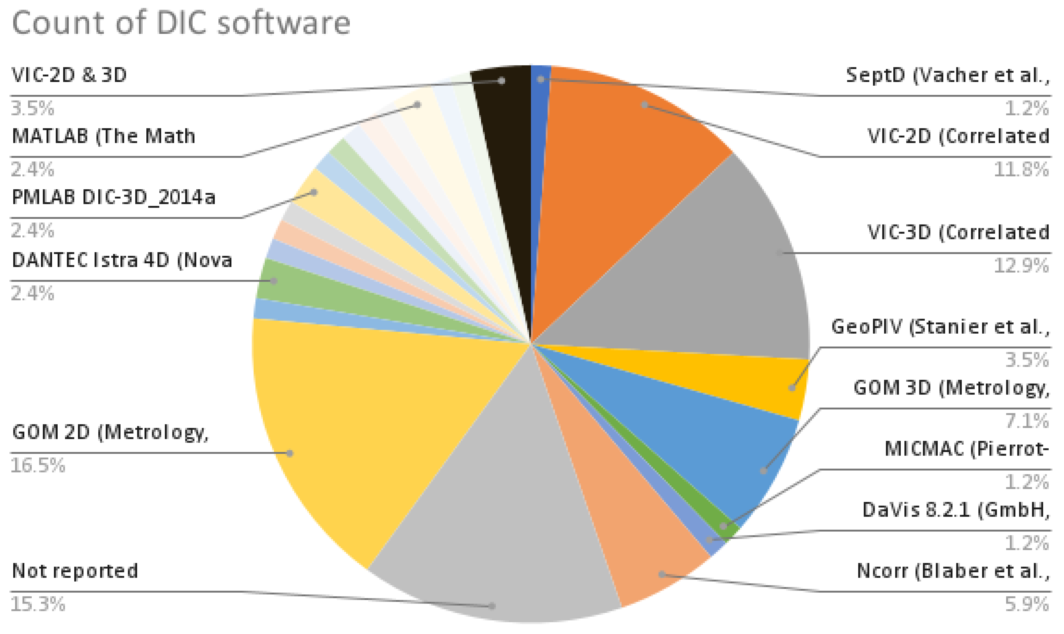
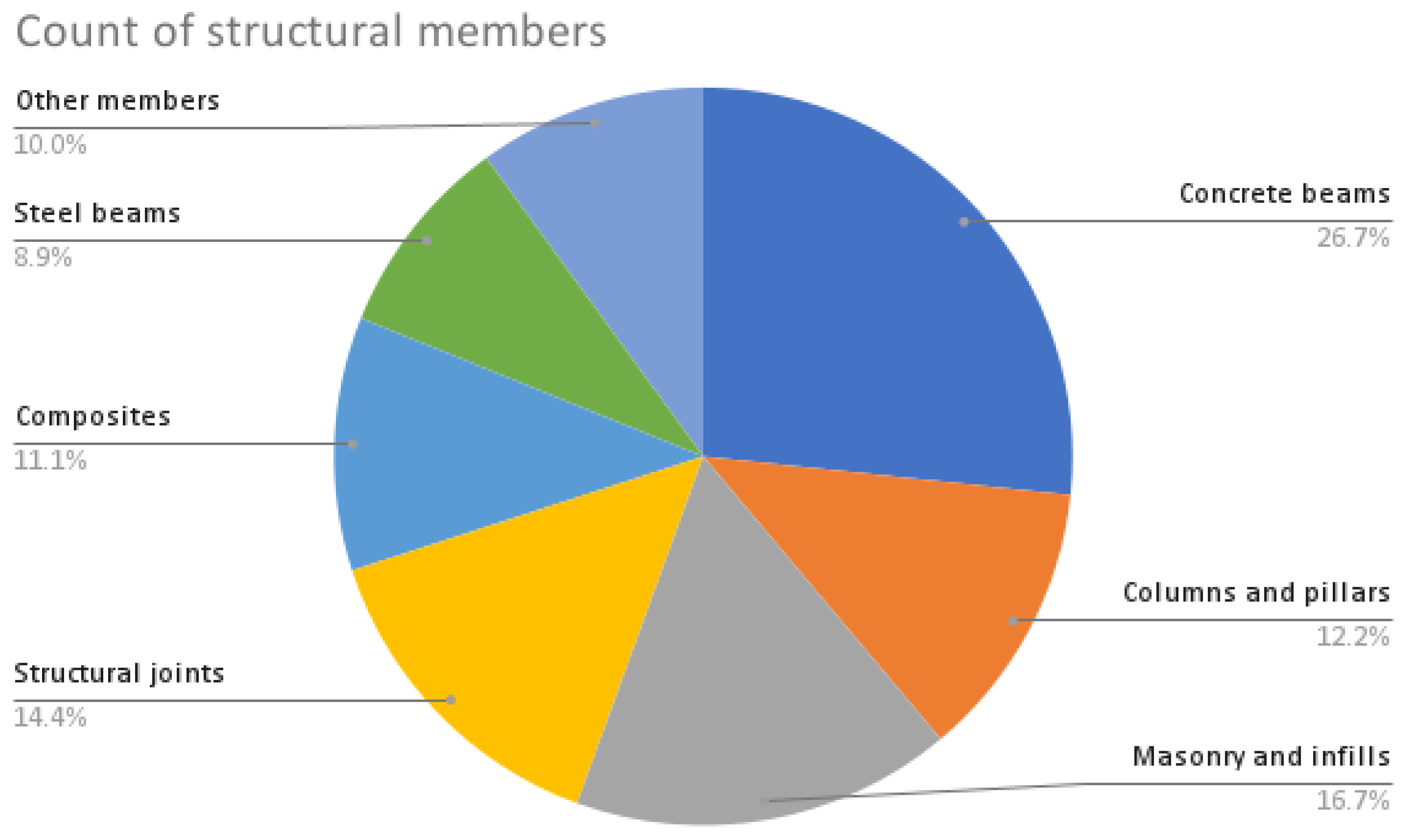
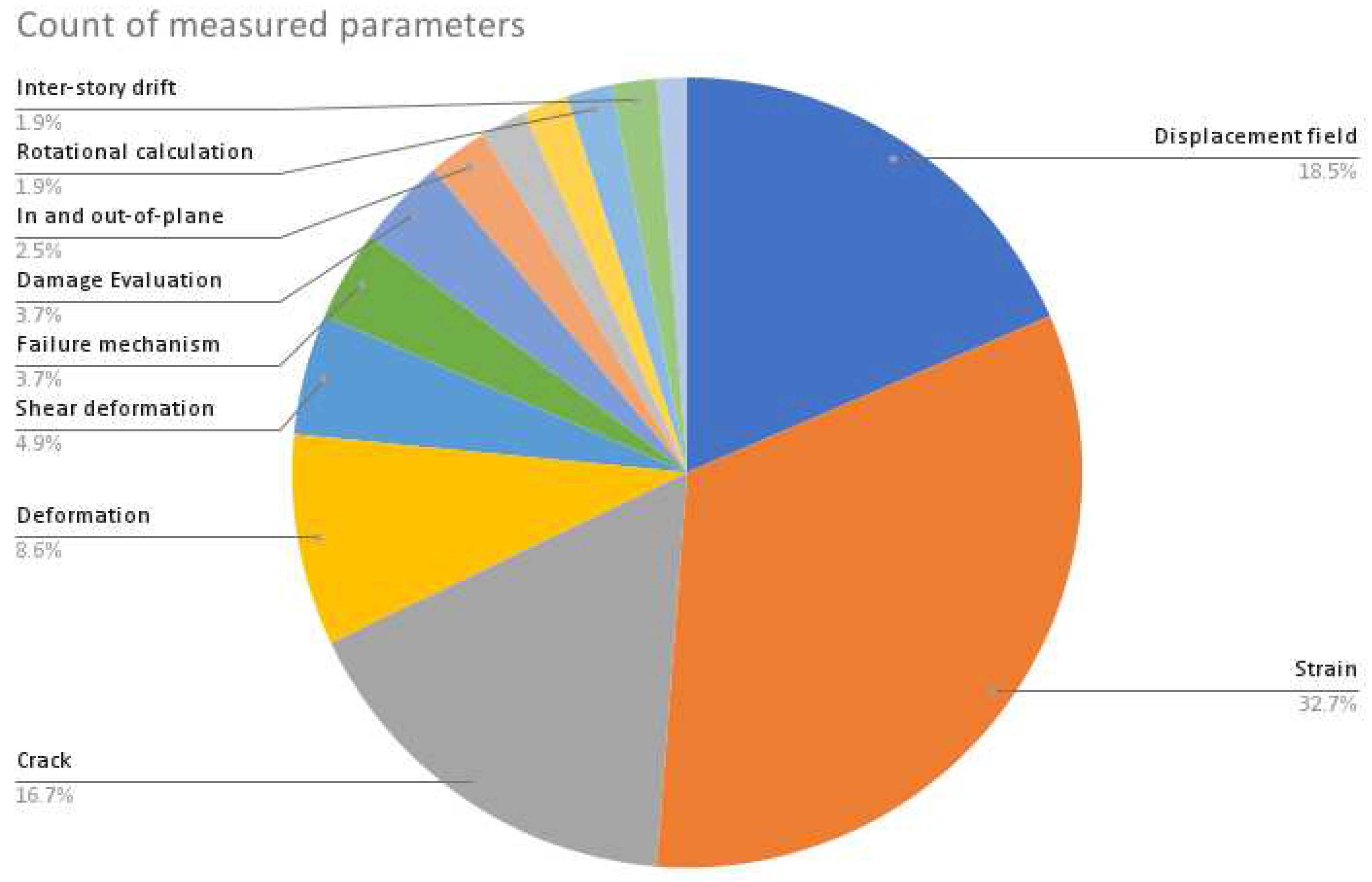
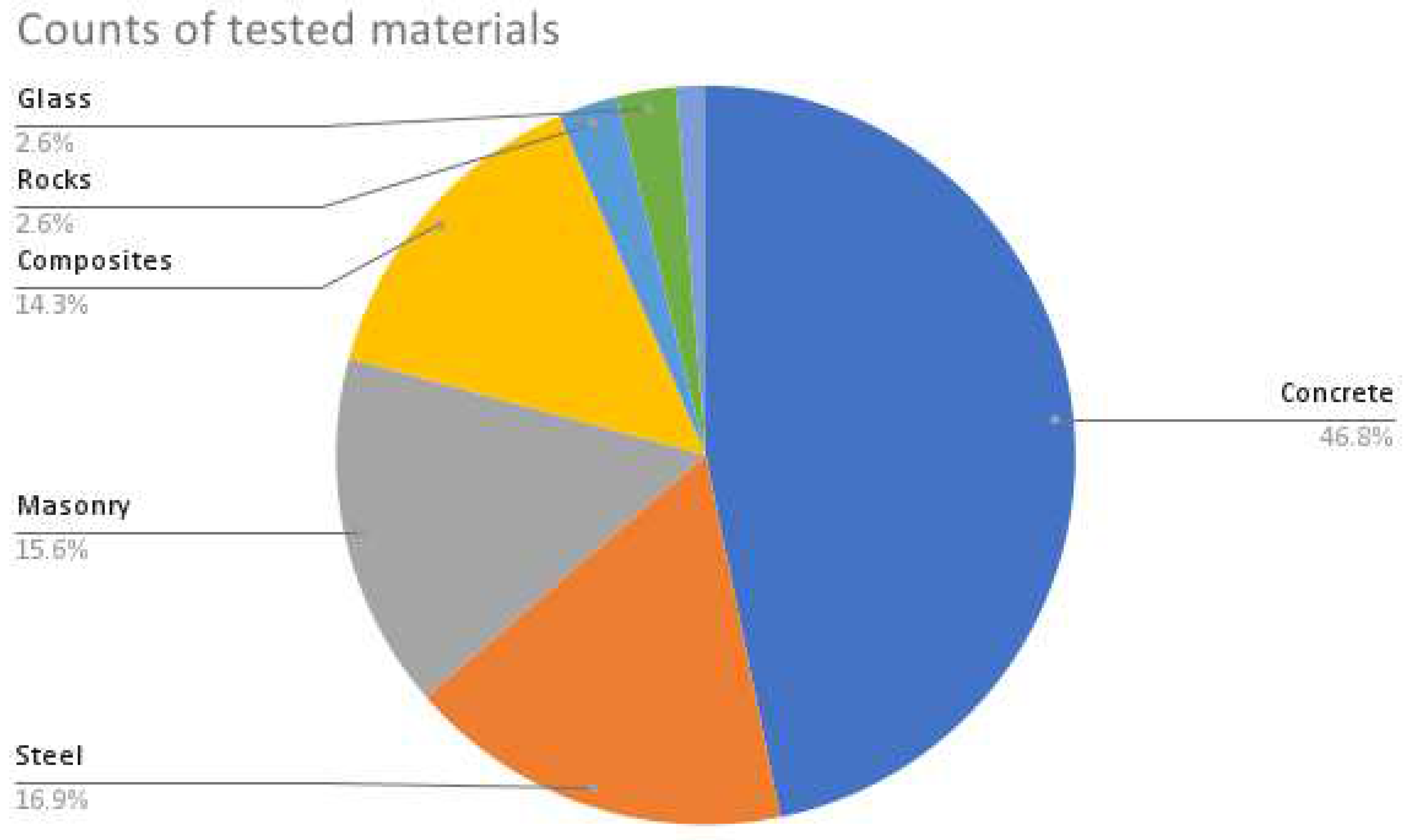
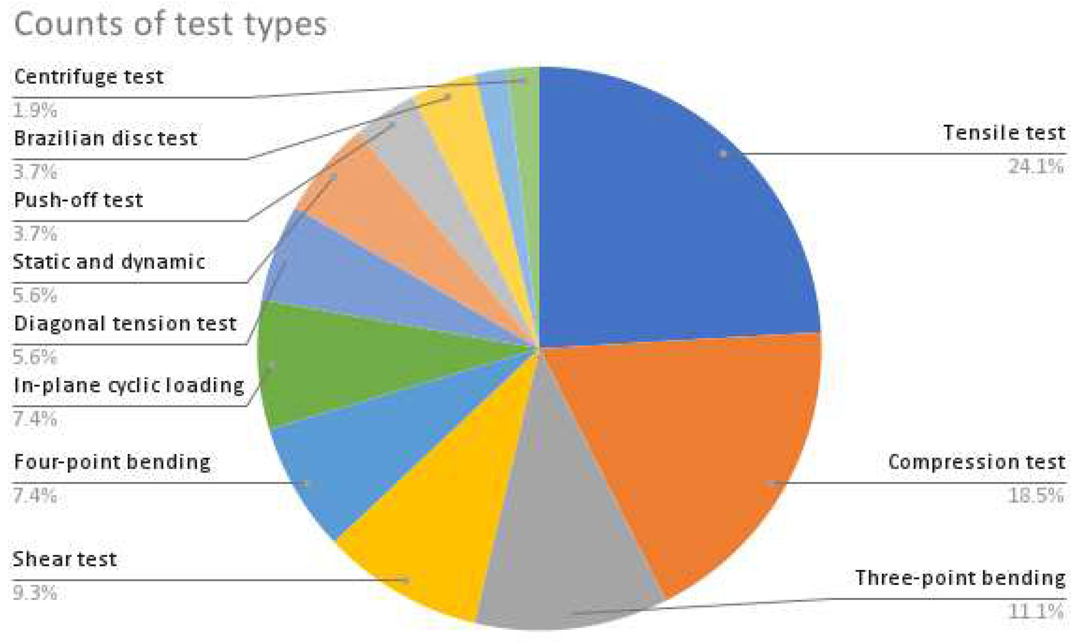
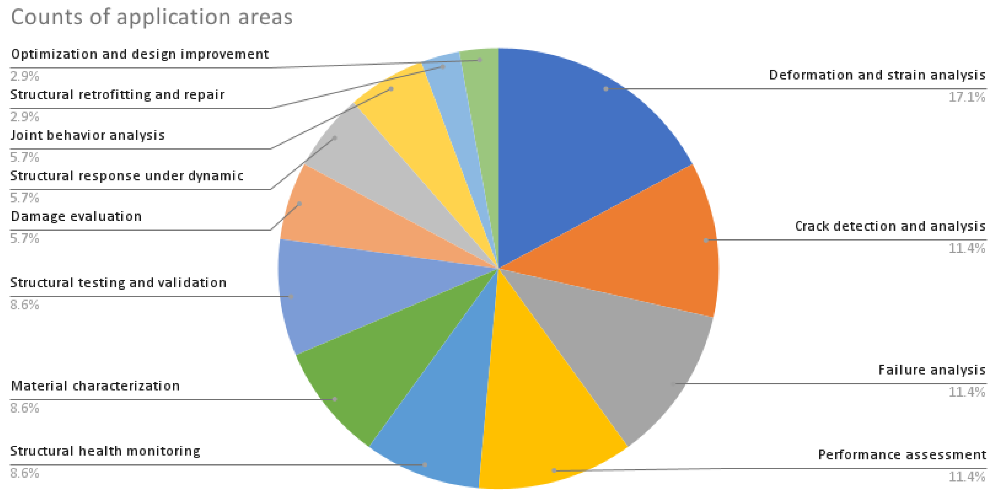
| No. | Structural Element | Authors |
|---|---|---|
| 1 | Concrete beams | Ferreira et al. (2011) Destrebecq et al. (2011) Dutton et al. (2014) Gencturk et al. (2014) Alam et al. (2015) Hamrat et al. (2016) Hoult et al. (2016) Omondi et al. (2016) Ruocci et al. (2016) Daghash & Ozbulut (2017) Gali & Subramaniam (2017) Pohoryles et al. (2017) Suryanto et al. (2017) Kearsley & Jacobsz (2018) Mehdi Mirzazadeh & Green (2018) Ghahremannejad et al. (2018) Murali Krishna et al. (2019) Słoński & Tekieli (2020) Zhou et al. (2021) Hou et al. (2021) Enfedaque et al. (2022) Dai & Li (2022) Aryanto et al. (2023) Becks et al. (2023) |
| 2 | Columns and pillars | Tung et al. (2014) Shih & Sung (2014) Dai et al. (2017) Demchyna et al. (2019), (2020) Chang & Huang (2020) Fallah Pour et al. (2020) Al-Kamaki (2021) Dai & Li (2022) Li et al. (2022) Sun et al. (2023) Allain et al. (2023) |
| 3 | Masonry and infills | Tung et al. (2008) Herbert et al. (2011) Salmanpour & Mojsilović (2013) Ghiassi et al. (2013) Guerrero et al. (2014) Furtado et al. (2015) Ghorbani et al. (2015) Nghiem et al. (2015) Ramos et al. (2015) Bolhassani et al. (2016) Mojsilović & Salmanpour, (2016) Kumar et al. (2019) Torres et al. (2020) Hossain et al. (2021) Howlader et al. (2021) |
| 4 | Structural joints | Sozen & Guler (2011) Desai (2016) Biscaia et al. (2018) Winkler et al. (2018) Peng et al. (2018) Gorman & Thouless (2019) Sun & Blackman (2020) Chang & Huang (2020) Ziaja et al. (2020) Kim et al. (2021) Paliwal & Ramji (2022) Wani et al. (2022) Xu et al. (2022) |
| 5 | Composites | Arora et al. (2011) Ghiassi et al. (2013) Gholizadeh (2016) Pisonero et al. (2017) Dai et al. (2017) del Rey Castillo et al. (2019) Fallah Pour et al. (2020) Janeliukstis & Chen (2021) Spencer et al. (2021) Lim et al. (2022) |
| 6 | Steel beams | Peddle et al. (2011) Yoneyama & Ueda (2012) Dutton et al. (2014) Shih & Sung (2014) Yu & Wu (2017) Beberniss & Ehrhardt (2017) Gorman & Thouless (2019) Tian, Zhao et al. (2021) |
| 7 | Other members | Beberniss & Ehrhardt (2017) Al-Mosawe et al. (2018) Tehrani et al. (2020) Sharafisafa et al. (2020) Christensen et al. (2021) Miikki et al. (2021) Zhang et al. (2021) Shuai et al. (2022) Thériault et al. (2022) |
| 1. Concrete Beams | |||
| Author | Specimen type and test method | Measured parameters | DIC specifications (Camera resolution, Measurement resolution, DIC software) |
| (Destrebecq et al., 2011) | full scale RC beam after 25 years of service in an industrial environment, four-point bending. | Displacement fields. Cracking process. |
1-MP, 1.38 px/mm, SeptD (Vacher et al., 1999) |
| (Tsangouri et al., 2013) | Plain concrete prisms 840mm long, 100mm wide, and 100mm high, three-point bending and a crack mouth opening displacement. | To visualize the crack opening and strain monitoring. |
5-MP, 20 px/mm, VIC-2D (Correlated Solutions, n.d.-a) |
| (Aggelis et al., 2013) | RC beams with a length of 2.5 m, a distance between the supports of 2.3 m, and a height and width of 0.3 m and 0.2 m respectively. A four-point bending test. | To measure the displacement and deformation fields at the side and the bottom surface of the beams. |
Not reported, Not reported, VIC-3D (Correlated Solutions, n.d.-b) |
| (Dutton et al., 2014) | Two different sections and materials, i.e., a steel HSS and a series of RC beams. Three-point bending. | longitudinal strains with the height at a section (curvature). |
18-MP, 27.8 px/mm, GeoPIV (Stanier et al., 2016; Take, 2015; White et al., 2003) |
| (Gencturk et al., 2014) | Full-scale deep I-beam prestressed concrete beam, shear capacity test. | In-plane and out-of-plane strains. Tensile and compressive strain locations. |
A pair of 12.6-MP, Not reported, GOM 3D (Metrology, 2019) |
| (Alam et al., 2014, 2015) | Geometrically scaled concrete beams under bending test. | fracture parameters such as crack openings and fracture zone size |
1.4-MP, 5.5-28.5 px/mm, VIC-2D (Correlated Solutions, n.d.-a) |
| (Omondi et al., 2016) | Prestressed concrete sleepers. Three-point Negative bending test. | critical damage areas evolution as a function of loading periods |
5-MP, 7.1 px/mm, VIC-3D (Correlated Solutions, n.d.-b) |
| (Ruocci et al., 2016) | RC beams. 1. Full-scale rectangular beams. 2. One-third scaled mock-ups. Four-point bending. | Evolution of the cracks pattern. Crack width, deformation, and strain monitoring. |
12-MP, 2 px/mm, MICMAC (Pierrot-Deseilligny & Paparoditis, 2006) |
| (Hoult et al., 2016) | RC beams with both small and large crack slip. Three and four-point bending test. | Crack width and crack slip measurement |
18-MP, 7.5-21 px/mm, GeoPIV (Stanier et al., 2016; Take, 2015; White et al., 2003) |
| (Hamrat et al., 2016) | Normal strength, high strength concrete, and high strength fiber concrete. Nine RC beams tested under four-point bending. | Strain, crack detection, development, and width measurements |
Not reported, Not reported, GOM 3D (Metrology, 2019) |
| (Pohoryles et al., 2017) | Composite-retrofitted RC beams. Four-point bending. | Strain and displacement monitoring, cracking, and debonding |
5-MP, 4.6 px/mm, DaVis 8.2.1 (GmbH, 2009) |
| (Gali & Subramaniam, 2017) | RC beams reinforced with steel fibres, the beams have dimensions 1500mm length, 125mm width, and 250mm depth. Four-point test, beams with a shear s/d ratio = 1.8. | Cracks and crack patterns identification. Tracking the response of the concrete across a crack. Horizontal and vertical displacements |
5-MP, 7-10 px/mm, VIC-2D (Correlated Solutions, n.d.-a) |
| (Suryanto et al., 2017) | Three RC beams, two with shear and one without shear reinforcement having dimensions 100×150×2000 mm3. Four-point loading test. | Crack mapping. longitudinal strain fields. |
18.4-MP, 4.4 px/mm, Ncorr (Blaber et al., 2015) |
| (Daghash & Ozbulut, 2017) | Five RC beams strengthened with NSM-BFRP having length of 2.1m. Four-point bending test. | Full-field strain and displacement contours. Mid-span deflection. Measurement of cracks width. |
5-MP, Not reported, Not reported |
| (Ghahremannejad et al., 2018) | Fibre-reinforced concrete beams six 1143 x 229 x 152 mm with and six 507 x 152 x 152 without longitudinal reinforcement. Four-point test. | Cracks kinematics (locations, number, spacing, and width). |
Not reported, Not reported, GOM 2D (Metrology, 2019) |
| (Murali Krishna et al., 2019) | A 24 (RCC) beams of size 1800 mm x150 mm x 200 mm. | To obtain the Moment (M) – Curvature (κ) relationships |
24.1-MP, Not reported, Ncorr (Blaber et al., 2015) |
| (Słoński & Tekieli, 2020) | Post-tensioned, precast crane runway I-section beams having dimensions of 6 m length and 0.8 m height after more than 50 years of exploitation. Three-point bending test. | Full-field strains. Detecting and locating the cracks on the surface. Combining DIC with R-CNN. |
Not reported, Not reported, μDIC (Olufsen et al., 2020) |
| (Domaneschi et al., 2021) | RC beam with 4 x 0.3 x 0.15 m. four-point bending test. | strain field |
Not reported, Not reported, Ncorr (Blaber et al., 2015) |
| (Hou et al., 2021) | full-scale RC beam that served for 60 years in an industrial environment, four-point bending test. | Strain, crack pattern and distribution, global and local deformation |
5-MP, 7.7 px/mm, DANTEC Istra 4D (Nova Instruments, 2016) |
| (Enfedaque et al., 2022) | polyolefin fibre RC beam. Three-point bending fracture test results. | Crack width. Crack opening displacement plane |
5-MP, 200 px/mm, Not reported |
| (Y. Dai & Li, 2022) | Coral aggregate concrete beam having dimensions of 1350 mm x 200mm× 120mm. Four-point bending. | A continuous-view multi-camera DIC to measure continuously the full-surface deformation. | Eight cameras, 5-MP, 290 px/mm, Not reported |
| (Aryanto et al., 2023) | Four concrete beams (150 x 150 x 600 mm) tested under four-points bending load. | Displacement fields. Crack propagation. |
18-MP, Not reported, Py2DIC (Belloni et al., 2019) |
| (Becks et al., 2023) | An inverted prestressed T-beam with a 1.4m long was tested in four-point bending. | Longitudinal compressive strain profile. |
12-MP, 10 px/mm, GOM 3D (Metrology, 2019) |
| 2. Columns and pillars | |||
| Author | Specimen type and test method | Measured parameters | DIC specifications (Camera resolution, Measurement resolution, DIC software) |
| (Demchyna et al., 2019) | Multilayer of glass and polymeric film sheets columns with 1000mm height, 5 x10mm thickness of sheets, and 70mm width. Compression test. | Determining the relative deformation and the strain of the glass. |
18-MP, Not reported, GOM 2D (Metrology, 2019) |
| (Bado et al., 2019) | Three types of RC tie members tested under uniaxial tensile loading where the samples clamped to the testing machine from the reinforcing bars. | To determine the surface displacements and strains of the columns. |
24-MP, 7.5-10 px/mm, GOM 2D (Metrology, 2019) |
| (Demchyna et al., 2020) | Glass columns of two series of 70 x 100 and 35 x100 sections both having 1m height. All samples were tested under compression load. | The use of 2D-DIC for glass columns under compression is not possible, because the columns are deformed in the direction of the three axes in space. For the study, it is necessary to use 3D-DIC. |
18-MP, Not reported, GOM 2D (Metrology, 2019) |
| (Al-Kamaki, 2021) | Pre-loaded RC columns through heating and cooling, then repaired with CFRP sheets. Compressions test. | to determine both latera and axial surface strains of the undamaged and post heated CFRP-confined columns. |
5-MP, 1.1 px/mm, VIC-3D (Correlated Solutions, n.d.-b) |
| (Y. Dai & Li, 2022) | Circular timber slender column with 100 mm in diameter and 1800mm height were tested under compression load. | Fully reconstructing the 3D shape of the circular column | Eight cameras, 5-MP, 290 px/mm, Not reported |
| (Z. Sun et al., 2023) | A precast concrete column reinforced with steel-FRP composite bars. Six columns (300 x 360 x 1400 mm) were tested under low reversed cyclic loading | Strain distribution. Moment-curvature curves. Plastic hinge region. Rotation calculation. |
Not reported, Not reported, Not reported |
| (Allain et al., 2023) | Concrete column under controlled load given vertical stress of 2.4 MPa in compression. | Displacement and strain field. |
12-MP, 22 px/mm, GlobalDIC and 7D (Vacher et al., 1999) |
| 3. Masonry walls and infills | |||
| Author | Specimen type and test method | Measured parameters | DIC specifications (Camera resolution, Measurement resolution, DIC software) |
| (Tung et al., 2008) | A 45˚ brick wall having dimensions of 30 x 40 cm and 150 x 120 cm steel-framed brick wall both tested under compression load. | Displacement and strain measurement. Crack observation |
6.3-MP, 5 px/mm, Not reported |
| (Herbert et al., 2011) | 1/6th scale masonry wall panels using a centrifuge to correctly model self-weight. A uniform lateral loading using airbag or non-uniform hydraulic loading. | Deflection of the panels. Identification of cracks in the wall panel. |
Not reported, Not reported, Not reported |
| (Salmanpour & Mojsilović, 2013) | Eleven full-scale unreinforced masonry walls ranging from (1.5 x1.6 m) to (3.6 x 2.6 m) were subjected to in-plane cyclic loading. | Deformation, strain, and crack distribution. |
12-MP and 36-MP, 1.5 – 1.7 px/mm, VIC-2D (Correlated Solutions, n.d.-a) |
| (Guerrero et al., 2014) | One single-bay infill, one single-bay partially infilled frame, Two-bay partially infilled frame, and squat infilled frame. All were subjected to cyclic lateral loading. | Strain fields. Struts inclination. |
Not reported, Not reported, CORRELI-Q4 (Besnard et al., 2006) |
| (Ghorbani et al., 2015) | Three full-scale masonry walls with dimensions of 2.4 x 2.4 m confined in a RC frame. All specimens were subjected to lateral in-plane cyclic loading. | Drift and diagonal deformation fields. Slip at the interface between the masonry and the concrete tie column. |
5-MP, 0.72 px/mm, VIC-3D (Correlated Solutions, n.d.-b) |
| (Nghiem et al., 2015) | a large-scale physical model reproducing both the soil-structure interaction and the masonry structure. Loading is applied by means of ground surface displacement. | Propose a way to quantify DIC measurement errors. Reconstruction of motion Displacement fields. Damage evaluation. |
4-MP, 7 px/mm, VIC-3D (Correlated Solutions, n.d.-b) |
| (Ramos et al., 2015) | A full-scale 4.2 x 2.3 m masonry wall confined with RC frame. Two tests were applied, one in-plane shear test and quasi-static out-of-plane cyclic test. | Displacement and strain fields. Principle strains. Out-of-plane displacement. |
4-MP, 2 px/mm, VIC-3D (Correlated Solutions, n.d.-b) |
| (Furtado et al., 2015) | A full-scale 4.2 x 2.3 m infilled RC frame subjected to in-plane test. One double leaf-panel. | Diagonal cracking, corner crushing, shear-friction failure. |
4-MP, 2 px/mm, VIC-3D (Correlated Solutions, n.d.-b) |
| (Bolhassani et al., 2016) | A full-scale 3.8 x 3.8 m partially grouted masonry shear wall tested under constant vertical compression load and horizontal lateral load using quasi-static displacement procedure. | Crack patterns. Diagonal tension and compression strains. Bed joint shear. Base strain. |
5-MP, 0.5 px/mm, GOM 3D (Metrology, 2019) |
| (Mojsilović & Salmanpour, 2016) | Ten full-scale unreinforced masonry walls ranging from (1.5 x1.6 m) to (3.6 x 2.6 m) were subjected to in-plane cyclic loading. | Deformation, strain, and crack distribution. |
12-MP and 36-MP, 1.5 – 1.7 px/mm, VIC-2D (Correlated Solutions, n.d.-a) |
| (Kumar et al., 2019) | Brick masonry prisms with dimensions of 520 x 220 x 100 mm tested under uniaxial compressions load. | In-plane strains and displacement. |
12-MP, Not reported, Ncorr (Blaber et al., 2015) |
| (Torres et al., 2020) | Six 710x710 mm brick masonry specimens tested under diagonal tension tests to evaluate the shear behaviour. | Identify the strain distribution at the moment of failure. Deformation measurement. Shear modulus. |
24-MP, 100 px/mm GOM 2D (Metrology, 2019) |
| (Hossain et al., 2021) | Different types of engineered masonry panels (2 x 2 m) made of semi-interlocking masonry (SIM) units subjected to in-plane cyclic loading. | von Mises strain fields. Joint opening and propagation. Horizontal and vertical displacement. |
8-MP and 36-MP, 7.4 – 21.5 px/mm, VIC-2D (Correlated Solutions, n.d.-a) |
| (Xie et al., 2023) | Four full-scale models of masonry infill having (3.1 x 3.0 m) surrounded by RC frame tested against out-of-plane loading. | Full-field out-of-plane deformation and strain concentration analysis. |
12-MP, Not reported, GOM 3D (Metrology, 2019) |
| 4. Composites materials | |||
| Author | Specimen type and test method | Measured parameters | DIC specifications (Camera resolution, Measurement resolution, DIC software) |
| (Arora et al., 2011) | GFRP sandwich structure having a speckled target of 1600 x 1300 mm subjected to a blast load. | Deformation monitoring. Failure mechanism. |
Two high-speed cameras of 1000FPS, 1-MP, 0.787 px/mm, GOM 3D (Metrology, 2019) |
| (Ghiassi et al., 2013) | FRP-masonry composite, to characterise the bonding interface through tensile and shear tests. | Longitudinal strain distribution in tensile test. Strain distribution along the bonded length in shear test. |
2-MP, 27 px/mm, GOM 2D (Metrology, 2019) |
| (Y. T. Dai et al., 2017) | CFRP-steel composite structure with dimensions of 150 x 150 x 500 mm. Shear test to monitor the bond-slip and compression test to monitor the buckling location. | To derive the bond-slip relationship between the CFRP-steel interface. To precisely locate the buckling and delamination of CFRP-steel composite. |
A multi camera system, 4-MP and 5-MP, Not reported, PMLAB DIC-3D_2014a (PMLAB, 2014). |
| (Tekieli et al., 2017) | Bond and tensile tests on composite reinforcements comprising different textiles and matrices. | Damage pattern (crack location and width) . Load transfer mechanism between composite-to- substrate. |
24-MP, 9 px/mm, Two software; CivEng Vision (Tekieli & Słoński, 2013) and Ncorr (Blaber et al., 2015) |
| (Pisonero et al., 2017) | Several DIC (2D and 3D) methods were employed using tensile tests to characterise 25 CFRP composite specimens. | The Young modulus. The Poisson ratio. Displacement and strain. |
Two systems: 2D: 18-MP, 3D: two 18-MP, Not reported, 2D: Ncorr (Blaber et al., 2015) 3D: MultiDIC (Solav et al., 2018) |
| (Górszczyk & Malicki, 2019) | Twenty specimens of 20 x 30 cm of Geosynthetics geogrids composites tested under uniaxial tensile loading. | Displacement and strain distribution. Maximum principal strain |
Not reported, Not reported, Not reported, |
| (Fallah Pour et al., 2020) | Ten FRP-confined concrete composite specimens tested under uniaxial compression load. | Axial, lateral, and Von Mises strains. |
2.8-MP, Not reported, VIC-3D (Correlated Solutions, n.d.-b) |
| (Janeliukstis & Chen, 2021) | Review static and dynamic tests of large-scale composite structure under various loadings such as buckling, crash, rotating, impact, and fatigue loads. | Full-field deformations. Displacement field. dynamic measurements. |
3.2-MP, 4-MP, 5-MP, 12-MP, 3.84 px/mm, GOM 2D & 3D (Metrology, 2019) |
| (Spencer et al., 2021) | Big Area Additive Manufacturing (BAAM) system while printing a full-size wall that has a building envelope of 6.1 x 2.4 x 1.8 (long x wide x tall). |
Thermal residual stresses monitoring. |
12.2-MP, 13.6 - 32 px/mm, VIC-2D (Correlated Solutions, n.d.-a) |
| (Lim et al., 2022) | Six FRP grids specimens consisting of BFRP and CFRP composites having a 300 mm length tested under uniaxial tensile loading. | Young’s Modulus. Vertical strain. |
18-MP, Not reported, Ncorr (Blaber et al., 2015) |
| (Chen et al., 2023) | A steel plate with 500mm long, 90mm width, and 7.5mm thickness with an edge crack that is repaired with CFRP sheet is subjected to uniaxial tensile load. | Displacement field. Crack growth propagation trajectories. |
8-MP, Not reported, VIC-2D (Correlated Solutions, n.d.-a) |
| 5. Structural joints | |||
| Author | Specimen type and test method | Measured parameters | DIC specifications (Camera resolution, Measurement resolution, DIC software) |
| (Sozen & Guler, 2011) | bolted steel connections specimens tested under uniaxial tensile load. | In-plane displacement distributions. |
0.78-MP, Not reported, MATLAB (The Math Works, 2020) |
| (Desai, 2016) | A steel beam-to-column connection specimen act as a cantilever loaded at its free. | Minimum measurable strains at six locations at the joint. |
36.3-MP, Not reported, GOM 2D (Metrology, 2019) |
| (Peng et al., 2018) | Two welded steel joints 20 mm thick and 25 x 20 section, tested under uniaxial tensile load. | The strain distribution. |
Not reported, Not reported, PMLAB DIC-3D_2014a (PMLAB, 2014). |
| (Biscaia et al., 2018) | Interfacial behaviour between a reinforcement material and a substrate through a series of single-lap shear tests. | Slip distribution. |
18-MP, Not reported, GOM 2D (Metrology, 2019), Ncorr (Blaber et al., 2015) |
| (Kavdir & Aydin, 2019) | Adhesively bonded single lap joints tested under tensile and shear loads. | Shear strain distributions. Strain distributions in the adhesive layer. |
Not reported, Not reported, GOM 2D (Metrology, 2019) |
| (Ziaja et al., 2020) | Pretensioned bolted beam-to-column connection anomaly detection during frame’s vibrations caused by harmonic excitation | Damage and anomaly detection in connections. |
1-MP, 15 px/mm, DANTEC Istra 4D (Nova Instruments, 2016) |
| (Chang & Huang, 2020) | A downscaled model of RC structure subjected to seismic vibrations. | Biaxial deformation at the beam-column region. Displacement and angle of inter-story drift. |
0.3-MP, Not reported, MATLAB (The Math Works, 2020) |
| (F. Sun & Blackman, 2020) | A double cantilever beam (DCB) with aluminium alloy substrate tested with a screw-driven tensile test machine. | Crack length measurement. Crack tip separation. Beam rotation. Energy release rate. |
18-MP, 28.5 px/mm, GOM 2D (Metrology, 2019) |
| (Kim et al., 2021) | A single-lap hybrid bonded-bolted (HBB) joints that has a bolted hole in the centre. The samples were tested under uniaxial load. | Shear strain around the bolt. Surface failure location identification. |
1-MP, 30.7 – 31.9 px/mm, MatchID (Colors, n.d.) |
| (Wani et al., 2022) | A five-story steel-frame braced structure with 6m height and 2 x 2 m plan area, subjected to bi-directional seismic excitations. | Displacement, acceleration, and velocity time history of the beam-column joint. Inter-story drift. Strain in joint and floor. |
8 high-speed cameras, 2.3-MP, 2.2 px/mm, VIC-2D & 3D (Correlated Solutions, n.d.-a) |
| (Xu et al., 2022) | Bolted fibre metal laminate joints consists of three layers of T3 aluminium of 0.4 mm thickness and four layers of GFRP. The samples were tested under uniaxial loading. | Displacement distribution. Compression and tension damage dominance regions. |
2.3-MP, Not reported, VIC-3D (Correlated Solutions, n.d.-b) |
| (Paliwal & Ramji, 2022) | Three test coupons each of the bonded, bolted, and hybrid joint tested under uniaxial tensile load. | Strain field of the joint. Strain field over the adhesive layer along the thickness. Failure mechanism. |
5-MP, Not reported, VIC-2D & 3D (Correlated Solutions, n.d.-a) |
| (Sousa et al., 2023) | Twenty-seven dry joint (flat, single-keyed, three-keyed) specimens of prestressed segmental bridges were subjected to push-off testes. | Joints sliding. Deformation and crack analysis, |
3.6-MP, Not reported, GOM 2D (Metrology, 2019) |
| 6. Steel structures | |||
| Author | Specimen type and test method | Measured parameters | DIC specifications (Camera resolution, Measurement resolution, DIC software) |
| (Peddle et al., 2011) | A W4x13 steel beam tested under three-point bending. | Beam deflection. |
2-MP, Not reported, VIC-2D (Correlated Solutions, n.d.-a) |
| (Yoneyama & Ueda, 2012) | A wide flange beam made of steel, 5m long, 0.2m in width and 8mm in thickness tested under three-point bending. | The deflections of the beam. |
8-MP, Not reported, Not reported |
| (M. H. Shih & Sung, 2014) | A five-story steel framed structure subjected to a series of dynamic experiments. | Dynamic analysis and damage detection |
2-MP, Not reported, Not reported |
| (Dutton et al., 2014) | A hollow steel section (HSS) beam having a 1.2m length and 0.1 x 0.1 m section loaded in three-point bending. | Longitudinal strains. Beam curvature. |
18-MP, 27.8 px/mm, GeoPIV (Stanier et al., 2016; Take, 2015; White et al., 2003) |
| (Ngeljaratan & Moustafa, 2017) | Free vibration and earthquake tests of steel frame having (0.5 length x 0.3 width x 1.1 height) | Displacement, velocity, and acceleration. |
high-speed 5-MP, Not reported, Not reported |
| (Gorman & Thouless, 2019) | An adhesively-bonded double-cantilever beam (DCB) having a length of 152mm loaded at its free end. | Displacement and strain. displacements within a cohesive zone. Rotation and shear strain. |
Two 5-MP, Not reported, VIC-2D (Correlated Solutions, n.d.-a) |
| (Tian, Zhao, et al., 2021) | A thin cantilever steel beam having 950 mm long subjected to static loads at five locations. | Scale factor. Full-field beam deflection. |
1.3-MP, Not reported, Not reported |
| 7. Slabs and other members | |||
| Author | Specimen type and test method | Measured parameters | DIC specifications (Camera resolution, Measurement resolution, DIC software) |
| (Al-Mosawe et al., 2018) | Uniaxial tensile test of dog-bone specimens. | Three speckle pattern configurations were used to measure the strain. |
5-MP, Not reported, VIC-2D & 3D (Correlated Solutions, n.d.-a) |
| (Ngeljaratan & Moustafa, 2019) | Three 1/3 RC two-span bridges tested under bidirectional earthquake. | Frequency estimation. Damping ratio, and mode shapes of the bridges. |
5-MP, Not reported, GOM 2D (Metrology, 2019) |
| (Tehrani et al., 2020) | Static loading of corrugated metal pipes. | Deflection and pipe profile. |
18-MP, 3 px/mm - 4 px/mm, GOM 2D (Metrology, 2019) |
| (Gehri et al., 2020; Mata-Falcón et al., 2020) | Reinforced concrete RC panel subjected to diagonal tension. | Automated crack width and slip measurement. |
29-MP, 2.63 px/mm, VIC-3D (Correlated Solutions, n.d.-b) |
| (Sharafisafa et al., 2020) | Bimrock disc specimens with 40 mm diameter and 15mm thickness, tested under tensile Brazilian disc test. | Crack initiation. Maximum shear strain. Overall failure pattern of three types of Bimrocks. |
NA-MP, 60-fps. Not reported, Not reported |
| (Zhang et al., 2021) | Series of semi-circular bending tests of the mine tailings rock material. | Strain distribution. Mode-I fracture toughness |
Not reported, 22.7 px/mm, VIC-3D (Correlated Solutions, n.d.-b) |
| (Christensen et al., 2021) | Three Overturned T-beam RC slabs under controlled laboratory conditions. Two of the concrete slabs (0.55 × 3.6 × 9.0 m) were stripped from in situ full-scale Ot-slab bridge having a 9m span and one downscaled slab. | Crack identification and assessment. |
Two cameras 20-MP, 18.7-MP, 0.69 px/mm – 1.72 px/mm, GOM 2D (Metrology, 2019) |
| (Thériault et al., 2022) | Double-L shape RC specimens, shear push-off testing. | Crack kinematics was observed using the full-field strain. |
18-MP, 24-MP, 10.8 px/mm to 11.8 px/mm, GOM 2D (Metrology, 2019) |
| (Luo et al., 2023) | Six ultra-high-performance fibre-reinforced and steel rebars reinforced concrete (500 mm long, 100 mm wide, and 50 mm thick) specimens were tested by direct tensile tests. | Full-field displacement and strain. Cracking behaviour. |
Two 9.1-MP, 13.3 px/mm, Not reported |
Disclaimer/Publisher’s Note: The statements, opinions and data contained in all publications are solely those of the individual author(s) and contributor(s) and not of MDPI and/or the editor(s). MDPI and/or the editor(s) disclaim responsibility for any injury to people or property resulting from any ideas, methods, instructions or products referred to in the content. |
© 2023 by the authors. Licensee MDPI, Basel, Switzerland. This article is an open access article distributed under the terms and conditions of the Creative Commons Attribution (CC BY) license (http://creativecommons.org/licenses/by/4.0/).


