1. Introduction
Vortex-Induced Vibrations (VIV), which is a subcategory of flow-induced instabilities, have been extensively studied by mechanical engineering researchers (Dong et al., 2022, Wang and Zhang, 2022, Jia et al., 2022). The reason for this interest lies in the fact that in practice many civil structures are subjected to the VIV phenomenon and fatigue caused by it, can be strongly damaging. To determine the oscillation amplitude of the structure under VIV, many researchers presented lots of semi-empirical models to simulate the wake dynamic, such as wake-oscillator models, force-decomposition models, and single DOF models (Qu and Metrikine, 2020, Zhao et al., 2022, Pigazzini et al., 2018).
In practical applications, structures are exposed to both cross-flow and in-line VIV, but oscillations in the transverse direction are commonly larger than the oscillations in the in-line direction. Therefore, many studies are focused on investigating the cross-flow VIV (Dahl et al. 2006; Dahl 2008). Jauvtis and Williamson (2004) showed that structures with mass ratios lower than 6, which is common among marine structures, allowing the structure to vibrate in both cross-flow and in-line directions, cause significant increases in the structure response (Dai et al., 2014). The reason for this increase is contributed to changes that appeared in the wake behind the structure as a result of restricting motion to only the transverse direction (Erturk 2009). Furthermore, Dahl et al. (2006) experimentally showed that when the natural frequency of structure in the in-line direction is twice (or near twice) that of the cross-flow direction, a so-called "dual-resonance" condition may occur (Erturk, 2009; Dai et al., 2014). The dual resonance condition happens in a wide frequency range near the frequency of Strouhal, supplemented by stable motion. It also goes along with the large harmonic part of lift force. This third-harmonic force can highly affect the fatigue life of the structure (Erturk and Inman, 2011).
In previous research, it is shown that the fluctuation of the lift force can accurately be described using phenomenological models with Van der Pol equation-based wake oscillator (Facchinetti et al. 2004). Facchinetti et al. (2004) introduced the van der Pol wake oscillator version of the VIV oscillator, which incorporates the three different couplings (i.e., velocity, displacement, and acceleration coupling), to predict the cross-flow VIV of a cylinder. The trend of the result obtained by the velocity and accelerate coupling models were similar to the experimental results but the oscillating amplitude exhibits an obvious difference. Farshidianfar and Zanganeh (2010) accurately predicted the response of the system for several mass-damping ratios by the so-called modified wake oscillator model, which is coupled with a nonlinear equation representing the dynamics of structure (Feng, 1968). Chen et al. (2022) revised the classic Van der Pol model to a new wake oscillator equation for simulating aerodynamic load on the circular cylinder. The result indicated the new coupled model can foresee the VIV response of circular cylinders at different Skop-Griffins and the complete frequency component of lift force. Srinil and Zanganeh (2013) introduced a model to predict combined cross-flow and in-line VIV, which uses the double Duffing and van der Pol equations to model structure and wake, respectively (Iwan and Blevins, 1974). Kim and Perkins (2002) proposed a coupled wake-oscillator model to compute lift and drag forces to predict the two-dimensional VIV of cable suspensions (Jeon et al., 2005). Zhang et al. presented several aerodynamic damping models to calculate the amplitude of VIV in a cylinder at various mass-damping conditions. They showed that the so-called mode shape correction factor for flexible cylinders depends on mechanical damping (Zhang et al, 2020). Zhang et al. studied the VIV of a circular cylinder, which is connected to a nonlinear stiffness. They showed that the result of the harmonically excited system can be used to analyze the effects of stiffness nonlinearity on the VIV response (Zhang et al, 2022).
The paper proposes a new model for predicting the combined in-line and cross-flow vibrations of a flexibly mounted rigid cylinder. In this model, the dynamics of the structure in two dimensions are modeled using the double Duffing equations, in which the nonlinear terms are used to couple in-line and cross-flow motions. In this study, a model is presented that utilizes double van der Pol equations to simulate the hydrodynamic forces of lift and drag. Furthermore, the acceleration coupling assumption is applied between the structure and wake variable. The main difference between this model and the previous models, with the acceleration coupling, is that the drag and lift forces are coupled through nonlinear quadratic terms.
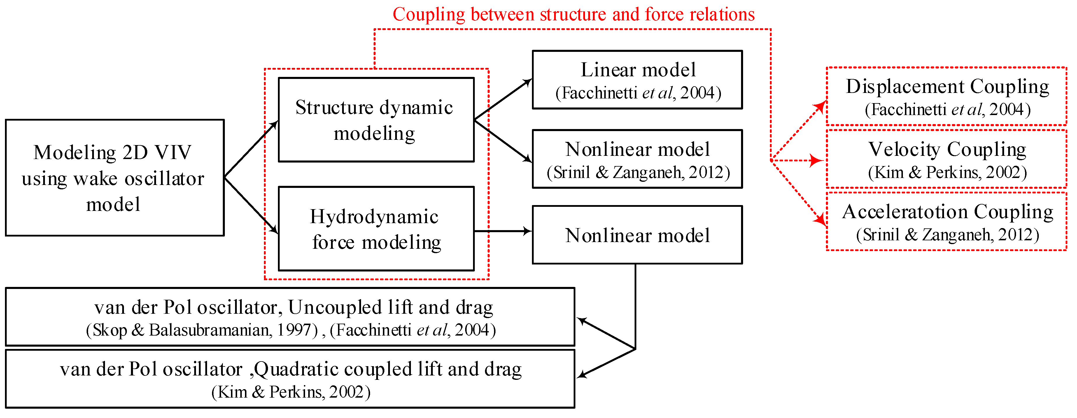
Figure 1 shows the different procedures that are used for modeling the 2D VIV. The closest references to the current study are mentioned in this figure.
Finally, the fully coupled nonlinear equations to model the discused VIV are numerically solved and the results are compared with experimental results.
2. Mathematical Modeling
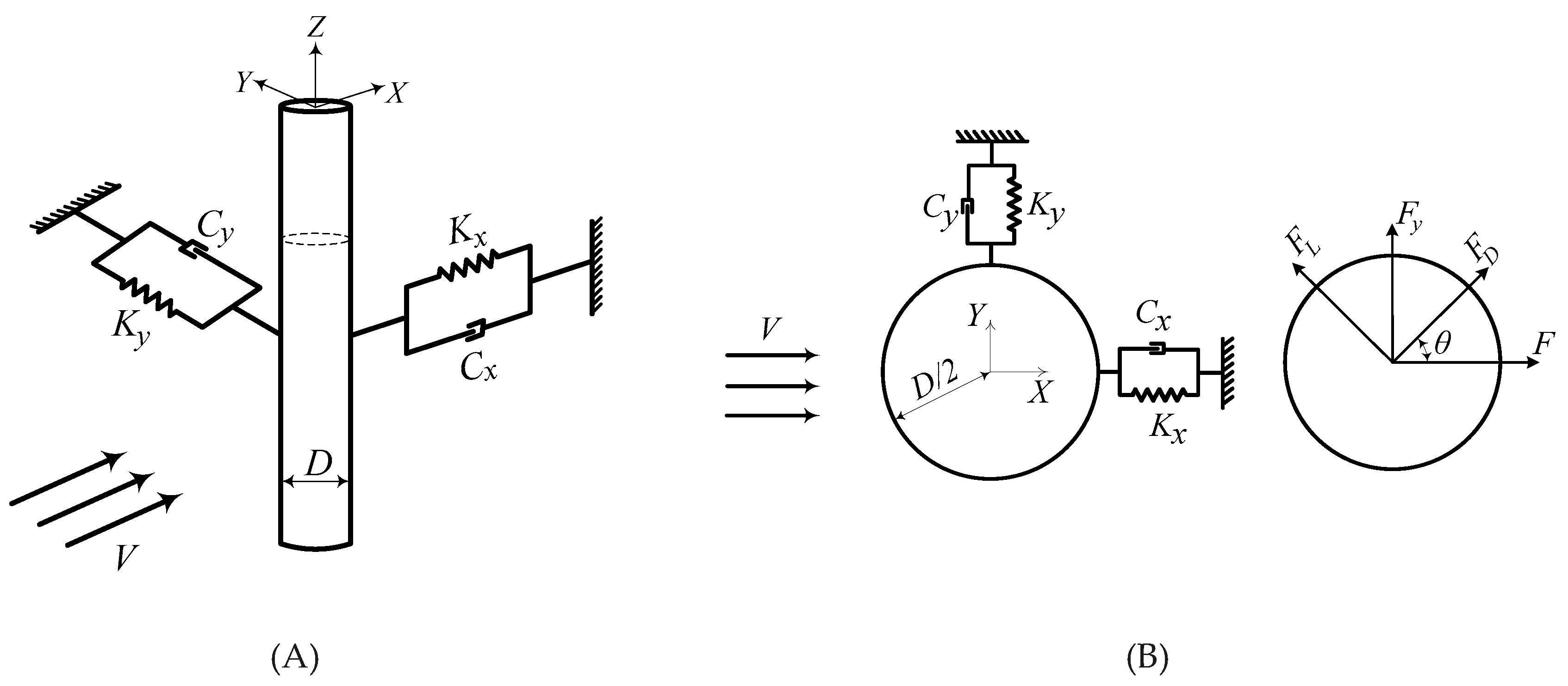
As shown in
Figure 2, consider a cylinder with diameter
D attached to two springs and viscous dampers in both in-line (
X) and cross-flow (
Y) directions. The system is considered to be infinitely long, which can be considered a structural oscillator. Alongside considering the nonlinear restoring force for the oscillating cylinder, variations of the hydrodynamic vortex-induced forces are described using nonlinear equations. In this study, to improve the accuracy of modeling, the nonlinear governing coupled equations of oscillations for a long cylinder, which is experimentally studied before (Srinil and Zanganeh, 2012) are coupled with numerically studied quadratic nonlinear equations of lift and drag fluctuations of suspended cable (Kim and Perkins, 2002). This system is located in a uniform steady flow with velocity
V and it can freely vibrate in both
X and
Y directions. In part (B) of
Figure 2,
FD and
FL are the drag and lift forces, which can be given by:
where
CD and
CL are respectively the drag and lift coefficients, which are variable with time. Regarding part (B) of
Figure 2 and assuming small attack angles (
θ), components of the lift and drag forces in
X and
Y directions are equal to:
Considering two coupled spring and damper systems as shown in
Figure 2, the nonlinear governing equation of oscillations is as follows (Srinil and Zanganeh, 2012):
where the fluid-added mass (
Mf) and the fluid-added damping (
Cf ) are defined as
Mf=0.25
ρπD2CM and
Cf=2
πStVρDγ (Bishop and Hassan, 1964). Note that
CM is the added mass coefficient and for a circular cylinder,
CM=1.0, and the stall parameter (
γ=0.25
CDπ-1St-1) is assumed a constant that is equal to 0.8 (Bishop and Hassan, 1964). The Strouhal number (
St) for cylinders in the subcritical range 300<Re<1.5×10
5 is equal to 0.2 (Erturk and Inman, 2011). Furthermore, in the above equations, the quantities
αx*,
αy*,
βx*, and
βy*are geometrical coefficients, which are related to the moving mass-spring system. For non-dimensionalizing, the governing equations of the cylinder motion, consider
y=
Y/D,
x=
X/D,
t=
Tωy. Therefore, the following relations can be re-written:
where Ω=ω
f/ω
y , ω
y=(K
y/m
y)
1/2, ω
f=2πStV/D , m
y=M
y+M
f , m
x=M
x+M
f, ω
y=(K
y/m
y)
1/2, , ω
x=(K
x/m
x)
1/2, λ=ω
x/ω
y, ζ
y=C
y/(2m
y ω
y) , ζ
x=C
x/(2m
x ω
x), μ
y=m
y/ρD
2, μ
x=m
x/ρD
2, α
x= α
x*D
2, α
y= α
y*D
2, β
x= β
x*D
2 , β
y= β
y*D
2, p=2C
D/C
D0, q=2C
L/C
L0 and V
r=2πV/Dω
y. Note that C
D0 and C
L0 are the drag and lift coefficients of a stationary (C
L0=0.3 (Karami and Inman, 2011) and C
D0=0.2 (Khalak and Williamson, 1999)). To increase the precision of the model, the interaction between fluid and structure in the above equations can be modeled considering the quadratic coupling between lift and drag fluctuations. The wake-oscillator model shows the coupling of lift and drag forces during the vortex-shedding process. Experimental results show that the frequency of the in-line oscillations along the drag force is twice of the cross-flow oscillations along the lift force. To do so, it is shown that the quadratic coupling between lift and drag can precisely foresee the VIV of a long cable (Kim and Perkins, 2002). In doing so, the governing equations for the drag and lift oscillations are considered as follows (Kim and Perkins, 2002):
where
ε is an artificial parameter and considering
κ7=12800, other coefficients
κi can be assumed considering the following relations (Kim and Perkins, 2002):
In the present study, κ1, κ3, and κ5 are constant coefficients.
3. Results and Discussion
In the last section, the nonlinear equations of motion for the VIV-based oscillations of a long cylinder and the quadratic coupling equations for long cables are presented. These models, which are presented from two different previous studies, are combined in the present study to precisely capture the VIV of the long cylinder. Then to show the application of this novel combination of equations, the result is compared with the presented experimental results of the referred study. The geometric and material parameters of the vibratory system and related fluid parameters are listed in
Table 1.
Table 1.
Vibratory cylinder and fluid parameters.
Table 1.
Vibratory cylinder and fluid parameters.
| Parameter |
Value |
| Cylinder diameter |
6.35 cm |
| Fluid density |
1025 kg/m3
|
| Strouhal number |
0.2 |
Regarding equations (11), (12), and (13), finding the coefficients
κi needs to assume three coefficients
κ1, κ3, and
κ5, which are simply named as “input coefficients” of equations (11) to (13). To show the effects of changing the input coefficients on the amplitude of the structural in-line (
Ax) and cross-flow oscillation (
Ay) equations (7) to (10) are numerically solved and the result respectively shown in
Figure 3 and
Figure 4. As shown in these figures, increasing
κ1 and decreasing
κ5 in constant
κ3 results in an increase in the maximum in-line and cross-flow amplitudes. Regarding these figures, it can be concluded
κ3 does not considerably affect the maximum amplitude of the cylinder oscillations. It should be noted that changing the input coefficients leads to reduced velocities, in which the upper limit of in-line and cross-flow oscillation amplitudes occurs in them, respectively varying between 6.5~6.8 and 7.4~8. Using the results shown in the user-oriented
Figure 3 and
Figure 4, the input coefficients can be tuned.
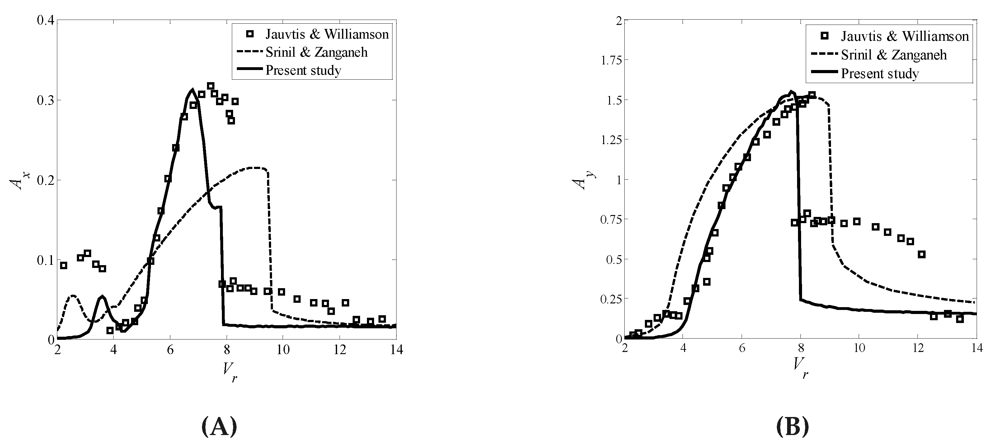
To exanimate the ability of the presented coupled model to precisely describe the VIV amplitude of the flexibly supported cylinders, in
Figure 5 amplitudes of the cross-flow and in-line VIV obtained using the discussed coupled model are compared with previous experimental (Abdelkefi et al., 2012) and numerical results (Barrero-Gil et al., 2012). The parameters of the inherent attribute of the circular cylinder presented in Jauvtis and Willliamson (2004) are substituted into the present coupled model to calculate the VIV response at different incoming flow velocities. Regarding the in-line direction, the vibrating amplitude of the circular cylinder calculated by the present model is superior to that of Srinil and Zanganeh (2012). Both the coupled model of the present study and that of Srinil and Zanganeh (2012) can well predict the maximum VIV amplitude, but those models cannot simulate the low branch of the VIV.
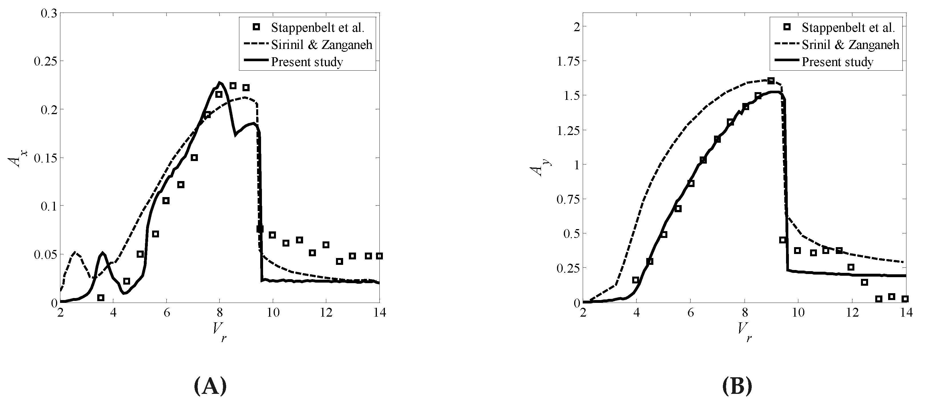
To illustrate the characteristics of universal adaptation of the present model, the experimental parameter presented in the study of Stappenbelt et al. (2007) is used in the present model to simulate the in-line and cross-flow oscillating amplitude of VIV occurring in a circular cylinder.
Figure 6 shows the comparison of the cross-flow and in-line VIV amplitudes that are achieved in this study, with another previous experimental result (Kim and Perkins, 2002) and numerical results (Barrero-Gil et al., 2012). The lock-in range and the maximum VIV amplitude obtained by the present model are very close to the experimental result for the in-line vibration. However, the result of the lock-in range presented by Srinil and Zanganeh (2012) possesses a large difference from the experimental result for the VIV of a circular cylinder. The present coupled model successfully predicts the VIV response in the cross-flow displacement. Therefore, regarding this figure and
Figure 6 can be concluded that the new coupled model can accurately describe the VIV amplitudes of the flexibly supported cylinders.
To study the accuracy of the coupled model, the results, which are found in the present study, are compared with the results, obtained using the previous coupled model (Srinil and Zanganeh, 2012). The relative error regarding previous experimental results presented by Jauvtis and Williamson (2004) and Stappenbelt
et al. (2007) is calculated and shown in the log scale in
Figure 7. Regarding to this figure it can be determined that in the pre-synchronization and synchronization regimes, the present coupled model can describe the vortex-induced vibration of the bluff body, better than the previous coupled model. However, the relative error of the VIV response obtained by the present coupled model is lower than that of Srinil and Zanganeh (2012). Therefore, the present model possesses a high precision for predicting the two-dimensional VIV of the circular cylinder, which is convenient to obtain the VIV response in engineering. It should be noted that the vibratory behavior of the VIV-based oscillations of the cylinder is nonlinear and based on the results, obtained in this study, it can be concluded the double Duffing nonlinear equations can predict the nature of this behavior, better than previous models. Therefore, as a result, the presented nonlinear model can precisely follow the well-known previously presented experimental result of the VIV of a circular cylinder.
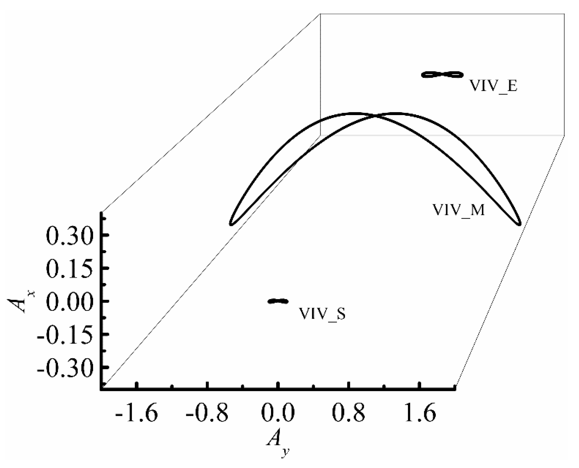
The oscillating trajectory of a circular cylinder is also an important parameter in engineering. Moreover, the vibrating form of the circular cylinder at variable reduced velocities (
Vr) exhibits different characteristics. The parameters of the circular cylinder given by Jauvtis and Williamson (2004) are used in the coupled model to calculate its trajectory at three important reduced velocities, i.e., the velocities of the VIV start (VIV_S), VIV peak amplitude (VIV_M), and VIV end (VIV_E). The results are given in
Figure 7. For the VIV_S and VIV_M, the trajectory of motion for the circular cylinder is a normal ‘8’ shape. This result illustrates that when it finishes one vibrating period in a cross-flow direction the cylinder has moved two periods in an in-line direction. Moreover, when the oscillating amplitude is maximum, the trajectory of the vibrating circular cylinder varies to a cuspidal ‘8’ shape, because the VIV in the direction of cross-flow is larger than in-line oscillations. All the results calculated by the present coupled model are consistent well with the experiment result given by Kang et al., (2016).
4. Conclusion
A fully coupled four-equation nonlinear system is proposed to accurately describe the VIV of a flexibly mounted rigid cylinder in two dimensions. The fully coupled nonlinear equations are numerically solved in time. The effect of changing the coefficients of the new terms, which are simply named “input coefficients” is shown on the amplitude of VIV and they are tuned to fulfill the cross-flow and the in-line response versus excitation frequency regarding experimental studies. Comparing results with other experimental data has shown that the presented model is more successful than previous models. It is shown that the presented novel model can follow the experimental results more accurately compared to the mentioned models in the lock-in range. This result is significant due to the fact that the oscillation amplitude of the structure in the lock-in range dramatically increases even to the extent that would cause failure in the structure. Moreover, the present coupled model successfully predicts the motion trajectory of the circular cylinder for occurring VIV.
Acknowledgments
This work was supported by Brain Pool Program through the National Research Foundation of Korea (NRF) funded by Ministry of Science and ICT (2022H1D3A2A01081886). This work was also supported by the National Research Foundation of Korea (NRF) grant, which is funded by the Korean government (MSIT) (No. 2020R1A5A8018822).
References
- Abdelkefi, A. (2016). "Aeroelastic energy harvesting: A review." International Journal of Engineering Science 100: 112-135.
- Abdelkefi, A., M. Hajj, et al. (2012). "Phenomena and modeling of piezoelectric energy harvesting from freely oscillating cylinders." Nonlinear Dynamics 70(2): 1377-1388. [CrossRef]
- Bai, X., Qin, W. (2014). Using vortex strength wake oscillator in modelling of vortex induced vibrations in two degrees of freedom. European Journal of Mechanics / B Fluids 48(6):165-173. [CrossRef]
- Barrero-Gil, A., S. Pindado, et al. (2012). "Extracting energy from Vortex-Induced Vibrations: A parametric study." Applied Mathematical Modelling 36(7): 3153-3160. [CrossRef]
- Bishop, R. E. D. and A. Y. Hassan (1964). "The Lift and Drag Forces on a Circular Cylinder Oscillating in a Flowing Fluid." Proceedings of the Royal Society of London. Series A. Mathematical and Physical Sciences 277(1368): 51-75.
- Chen, G. B., Chen, W.L., Min, X. W., Gao, D. L.(2022). "A coupled model for vortex induced vibration of a circular cylinder with and without passive-jet flow control." Journal of Wind Engineering and Industrial Aerodynamics. 110:103541. [CrossRef]
- Cook-Chennault, K., N. Thambi, et al. (2008). "Powering MEMS portable devices—a review of non-regenerative and regenerative power supply systems with special emphasis on piezoelectric energy harvesting systems." Smart Materials and Structures 17(4): 043001. [CrossRef]
- Dahl, J., F. Hover, et al. (2006). "Two-degree-of-freedom vortex-induced vibrations using a force assisted apparatus." Journal of Fluids and Structures 22(6): 807-818. [CrossRef]
- Dahl, J. J. M. (2008). Vortex-induced vibration of a circular cylinder with combined in-line and cross-flow motion, Massachusetts Institute of Technology.
- Dai, H., A. Abdelkefi, et al. (2014). "Modeling and Identification of Circular Cylinder-based Piezoaeroelastic Energy Harvesters." Energy Procedia 61: 2818-2821. [CrossRef]
- Dai, H., A. Abdelkefi, et al. (2014). "Theoretical modeling and nonlinear analysis of piezoelectric energy harvesting from vortex-induced vibrations." Journal of Intelligent Material Systems and Structures 25(14): 1861-1874. [CrossRef]
- Dong, L., J. Jia, and L. Zhang (2022). "Numerical Analysis on Spanwise Correlation of Vortex-Induced Force of Split Double-Box Beam." Applied Sciences (2022): 12668. [CrossRef]
- Erturk, A. (2009). Electromechanical Modeling of Piezoelectric Energy Harvesters.
- Erturk, A. and D. J. Inman (2011). Piezoelectric energy harvesting, John Wiley & Sons.
- Facchinetti, M. L., E. De Langre, et al. (2004). "Coupling of structure and wake oscillators in vortex-induced vibrations." Journal of Fluids and structures 19(2): 123-140. [CrossRef]
- Farshidianfar, A. and H. Zanganeh (2010). "A modified wake oscillator model for vortex-induced vibration of circular cylinders for a wide range of mass-damping ratio." Journal of Fluids and Structures 26(3): 430-441. [CrossRef]
- Feng, C. (1968). The measurement of vortex induced effects in flow past stationary and oscillating circular and d-section cylinders, University of British Columbia.
- Gabbai, R.D. Benaroya, H. (2005). An overview of modeling and experiments of vortex induced vibration of circular cylinders, J. Sound Vib. 282 575–616. [CrossRef]
- Iwan, W. and R. Blevins (1974). "A model for vortex induced oscillation of structures." Journal of Applied Mechanics 41(3): 581-586. [CrossRef]
- Jauvtis, N., Williamson, C. (2004). "The effect of two degrees of freedom on vortex-induced vibration at low mass and damping." J Fluid Mech, 509, 23-62. [CrossRef]
- Jeon, Y., R. Sood, et al. (2005). "MEMS power generator with transverse mode thin film PZT." Sensors and Actuators A: Physical 122(1): 16-22. [CrossRef]
- Jia, L., Liu, Y., Zhang, M., Fu, S., & Ren, H. (2022). Experimental Research on Vortex-Induced Force Characteristics of Flexible Riser with Buoyancy Module and Strakes. Applied Sciences, 12(12), 6180. [CrossRef]
- Karami, M. A. and D. J. Inman (2011). "Analytical modeling and experimental verification of the vibrations of the zigzag microstructure for energy harvesting." Journal of Vibration and Acoustics 133(1): 011002. [CrossRef]
- Khalak, A. and C. Williamson (1999). "Motions, forces and mode transitions in vortex-induced vibrations at low mass-damping." Journal of fluids and Structures 13(7): 813-851. [CrossRef]
- Kim, W.-J. and N. Perkins (2002). "Two-dimensional vortex-induced vibration of cable suspensions." Journal of Fluids and Structures 16(2): 229-245. [CrossRef]
- Kang, Z., Ni, W., Sun, L. (2016). "An experimental investigation of two-degrees-of-freedom VIV trajectories of a cylinder at different scales and natural frequency ratios. " Ocean engineering, 126, 187-202. [CrossRef]
- Srinil, N., Zanganeh, H. (2012). "Modelling of coupled cross-flow/in-line vortex-induced vibrations using double Duffing and van der Pol oscillators." Ocean Engineering, 53, 83-97. [CrossRef]
- Srinil, N., Zanganeh, H. (2013). "Two-degree-of-freedom VIV of circular cylinder with variable natural frequency ratio: Experimental and numerical investigations." Ocean Engineering, 73, 179-194. [CrossRef]
- Stappenbelt, B., Lalji, F., Tan, G. (2007). "Low mass ratio vortex-induced motion." 16th Australasian Fluid Mechanics Conference, Gold Coast, Australia, December, pp. 2-7.
- Wang, L., and Zhang W. (2023). "The Influence of Chamfered and Rounded Corners on Vortex-Induced Vibration of Super-Tall Buildings." Applied Sciences, 1049. [CrossRef]
- Zhang, M, Xu F., and Oiseth O. (2020), "Aerodynamic damping models for vortex-induced vibration of a rectangular 4:1 cylinder: Comparison of modeling schemes" Journal of Wind Engineering and Industrial Aerodynamics, 104321.
- Zhang, M., Song, Y., Abdelkefi, A., Yu, H., & Wang, J. (2022). Vortex-induced vibration of a circular cylinder with nonlinear stiffness: prediction using forced vibration data. Nonlinear Dynamics, 108(3), 1867-1884. [CrossRef]
- Qu, Y., & Metrikine, A. V. (2020). A single van der pol wake oscillator model for coupled cross-flow and in-line vortex-induced vibrations. Ocean Engineering, 196, 106732. [CrossRef]
- Zhao, J., Thompson, M. C., & Hourigan, K. (2022). Decomposition of fluid forcing and phase synchronisation for in-line vortex-induced vibration of a circular cylinder. Journal of Fluid Mechanics, 941, R4. [CrossRef]
- Pigazzini, R., Contento, G., Martini, S., Puzzer, T., Morgut, M., & Mola, A. (2018). VIV analysis of a single elastically-mounted 2D cylinder: Parameter Identification of a single-degree-of-freedom multi-frequency model. Journal of Fluids and Structures, 78, 299-313. [CrossRef]
|
Disclaimer/Publisher’s Note: The statements, opinions and data contained in all publications are solely those of the individual author(s) and contributor(s) and not of MDPI and/or the editor(s). MDPI and/or the editor(s) disclaim responsibility for any injury to people or property resulting from any ideas, methods, instructions or products referred to in the content. |
© 2023 by the authors. Licensee MDPI, Basel, Switzerland. This article is an open access article distributed under the terms and conditions of the Creative Commons Attribution (CC BY) license (http://creativecommons.org/licenses/by/4.0/).
