1. Introduction
Rayleigh-Bénard convection() is induced by the density variation in a layer of a Newtonian fluid heated from below. The fluid in the system convects when the temperature difference between the horizontal boundaries crosses a threshold value. One then says that the onset of convection has occurred. The study of onset is very important in understanding and describing the stability of the system. The problem is generally studied in the following two geometries:
Rectangular geometry and
Cylindrical geometry.
Of the various regimes that one can study concerning this problem, it is the two-dimensional problem in both the geometries that can be analysed well analytically and compared. In the case of the cylindrical geometry we would require the imposition of axisymmetry for the sake of comparison with the rectangular
problem. In what follows we present a literature survey of such comparable problems. The main focus of this paper is on the cylindrical
problem with axisymmetry with the well explored two-dimensional rectangular
problem being used mostly for comparison and completeness. We first survey articles on
in a rectangular geometry[
1,
2,
3,
4,
5]. The two-dimensional analysis of
in a Boussinesq fluid bounded between two horizontal free surfaces is investigated by Moore and Weiss[
1]. In their linear and nonlinear studies of the problem, different values of the Prandtl number,
, and the Rayleigh number(upto 1000 times of its critical value) are considered. They found from the study that for
the heat flux is found to be maximum for cells whose width is between 1.2 to 1.4 times of its layer depth and for
the heat flux is maximum for square cells. Bergé and Dubois[
2] presented physical reasons for the instability mechanisms in
. Two phenomena near and close to the critical point are presented in the framework of a mean field approach. The dynamics of the convective pattern and the selection of the wave number is considered in the case of large aspect ratio cells. Roche et al.[
3] proposed a model to find side wall effects on
. They found that when the conductivity of the wall material is greater than the conductivity of the fluid then the wall effect is regulated by the wall number where the wall number is defined as the ratio of the empty cell conductivity to that of the conductivity of the stagnant fluid. Stevens et al.[
4] investigated the influence of lateral thermal boundary conditions on heat transport in
using the DNS(direct numerical simulation) method. They found from the study that the heat transport is maximum for an isothermal side wall boundary condition compared to the adiabatic one. Wen et al.[
5] constructed the conditional upper and lower bounds for the heat transport in
. The upper bound estimation is found for stress-free boundary condition and the lower bound estimate is determined for both stress-free and no-slip boundary conditions. The results show that the lower bound captures the classical result of
scaling of the Rayleigh number.
We now present a detailed literature survey of the cylindrical
problem. Liang et al.[
6] numerically investigated the buoyancy driven convection in an axi-symmetric cylindrical geometry by considering temperature-dependent viscosity. They found that the temperature-dependent viscosity has no effect on the stability or the rate of convergence of the numerical methods. Stork and Müller[
7] experimentally investigated axi-symmetric thermoconvective flows in circular vessels(cylinder and annulus). The critical Rayleigh number was obtained as a function of the aspect ratio(diameter to height ratio) and the annular width of the enclosure. The influence of lateral walls with various thermal conductivities and boundary wall thicknesses were examined. Charlson and Sani[
8] investigated the onset of convection in an axi-symmetric cylindrical enclosure bounded by rigid boundaries using the Rayleigh-Ritz method. The aspect ratio(radius/height) in the range from 1 to 8 is considered in the study. The obtained results are validated with the experimental works of Koschmieder[
9,
10,
11]. Later, Charlson and Sani[
12] extended their work on axi-symmetric flow to non-axi-symmetric flows. Hébert et al.[
13] simulated and experimentally studied the onset of convection and the convection pattern in a cylindrical enclosure(with no axisymmetry assumption) with aspect ratio(diameter/height) in the range:[1, 9]. They observed one and two convection rolls in the aspect ratio ranges
and
respectively. Wang et al.[
14] numerically investigated thermal convection in a cylinder of unit aspect ratio(radius/height). Various ranges of Prandtl and Rayleigh numbers were considered in the study. The transition from a steady flow to an oscillatory flow is found to occur at small Rayleigh number and small Prandtl number. Yu et al.[
15] numerically simulated the onset of convection and studied the convective pattern in a circular cylinder for intermediate values of the aspect ratio(diameter/height) in the range of [6, 20]. They found from the study that the critical Rayleigh number decreases asymptotically for an increase in the value of the aspect ratio. They also found that the mode of onset switches between two values, 1 and 0, that correspond to even and odd values respectively of the aspect ratio. Li et al.[
16] numerically studied the onset of convection and the heat transport for two different values of aspect ratios(radius/height), 1 and 2, with the Prandtl number taken as 1. They found from the study that the flow patterns are symmetric for the considered two values of the aspect ratio. They also showed that the heat transport varies directly on the aspect ratio.
Analogous cylindrical
problems in a porous medium are also investigated by many[
17,
18,
19,
20,
21,
22]. Though our study does not concern a porous medium, these articles are useful in obtaining an analytical solution in the present study. Zebib[
17] studied the linear stability analysis of natural convection in a porous cylinder. He showed that the asymmetric modes are the preferred modes of convection except in the range of aspect ratios(radius/height):[1.09, 1.28], where the axi-symmetric mode of convection is preferred. Bau and Torrance[
18] investigated the onset of
in a cylindrical annuli filled with a porous medium. They considered two types of top-wall boundary conditions(permeable and impermeable) and they found that the system is more unstable in the case of the permeable boundary condition compared to the case of the impermeable one. Haugen and Tyvand[
19] studied the onset of convection in a densely packed porous cylinder whose boundaries are impermeable and perfectly heat conducting. They found that the axi-symmetric mode of convection is always the preferred one. They also found that the Rayleigh number is a smooth function of the radius to height ratio in the case of the conducting boundary condition which is opposite to what is seen in the case of an insulating boundary. Bringedal et al. [
20] investigated the onset of
in a cylindrical annuli with either insulating or heat conducting boundary condition. They found from the study that the effect of inner radius on onset is more significant in the case of heat conducting boundaries compared to the insulating boundary condition. The
induced in a vertical porous cylinder by subjecting its lower horizontal wall to uniform heat flux and by maintaining the upper horizontal wall with an uniform temperature is investigated analytically by Barletta and Storesletten[
21]. They carried out a linear stability analysis and an analytical solution is obtained by using the Mathieu function instead of the Bessel function. Siddheshwar and Lakshmi[
22] analytically studied the onset of convection and heat transport in cylindrical porous enclosures/annuli saturated by a Newtonian liquid or nanoliquids. Four different types of enclosures, viz., tall, square, shallow and very shallow, are considered in the study. They found from their study that the critical Darcy-Rayleigh number decreases with increase in the value of the aspect ratio(height/radius). Also, for the four different types of enclosures, they did a nonlinear study and showed that the tall enclosure transports maximum heat and very shallow enclosure transports the least. Recent developments in
is covered in many recent articles [
23,
24,
25,
26].
From the literature survey of the problems in a cylindrical geometry, it is apparent that the following aspects have not been studied:
The analytical study concerning onset of convection in cylindrical enclosures.
Clear information about the cell aspect ratio.
An explicit analytical expression connecting the number of cells and the aspect ratio.
Similarities and fundamental differences between the results of cylindrical and rectangular geometries.
These aforementioned unconsidered aspects are chosen for investigation in this paper.
The present paper is organised as follows:
Section 2 includes the schematic representation of an experimental set up and the complete details of the physical model considered. In
Section 3 we present the governing equations, boundary condition and a standard procedure of non-dimensionalisation. The quiescent basic state and perturbation solutions will also be presented. In
Section 4, we transform the governing equations into a product of three Helmholtz equations and then find an expression for the critical Rayleigh number using a linear stability analysis of cylindrical and rectangular
problems. In the next section on results and discussion, the information on the formation and the nature of the cells, the cell width and the wave number is presented and discussed in great detail. Explicit expressions for the number of cells and the critical Rayleigh number as a function of aspect ratio are obtained. We also list out all possible similarities and differences between the results of cylindrical and rectangular enclosures. Finally, in
Section 6 we report the major conclusions of the study.
2. The Physical Model
The experimental set up of Stork and Müller[
7] for the thermal convection problem in a cylindrical geometry involves a copper plate of
thickness as the lower horizontal boundary. Due to its high thermal conductivity it supports the perfect isothermal condition. A glass plate of thickness
was considered as the upper horizontal plate which helps in making experimental observations. The thermal insulation condition of the lateral wall was achieved by considering a PVC material of thickness
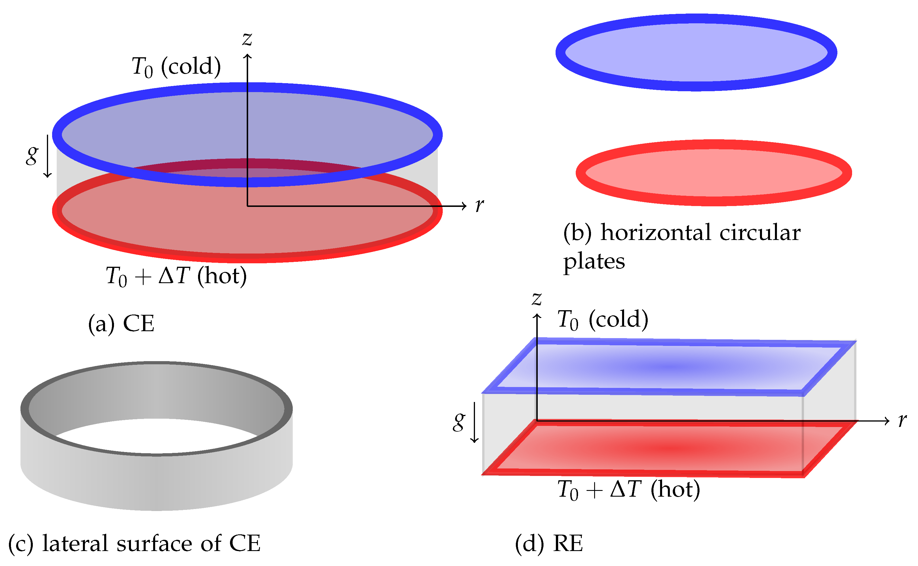
. The schematic of the same is given in
Figure 1. One may similarly write down the schematic representation of the experimental set up for a rectangular enclosure.
The present analysis simulates this kind of experimental set up but with the following assumptions:
The horizontal and lateral wall thicknesses are neglected thereby meaning that the walls are thin. Free and impermeable boundary condition is adopted in the analysis.
Axi-symmetric convective motion is assumed in the case of cylindrical enclosure.
The horizontal and the lateral boundaries are assumed to be perfectly isothermal and adiabatic boundaries respectively.
-
The roll pattern is circular in the case of and straight in the case of .
Liang et al.[
6] in their experiment observed purely a circular roll pattern in a cylindrical enclosure of depth upto
. Hence in the present analysis, we choose maximum height of
as
.
These assumptions make our problem idealistic and help in obtaining an analytical solution.
The present model considers
of a Newtonian liquid(water) in two different geometries(cylindrical and rectangular). We assume common notation for the cylindrical/Cartesian coordinates
. In the case of the cylinder,
r is taken from the axis of the cylinder towards the lateral boundary while
r is taken from the left wall towards the right wall in the case of the rectangular enclosure. In both the geometries,
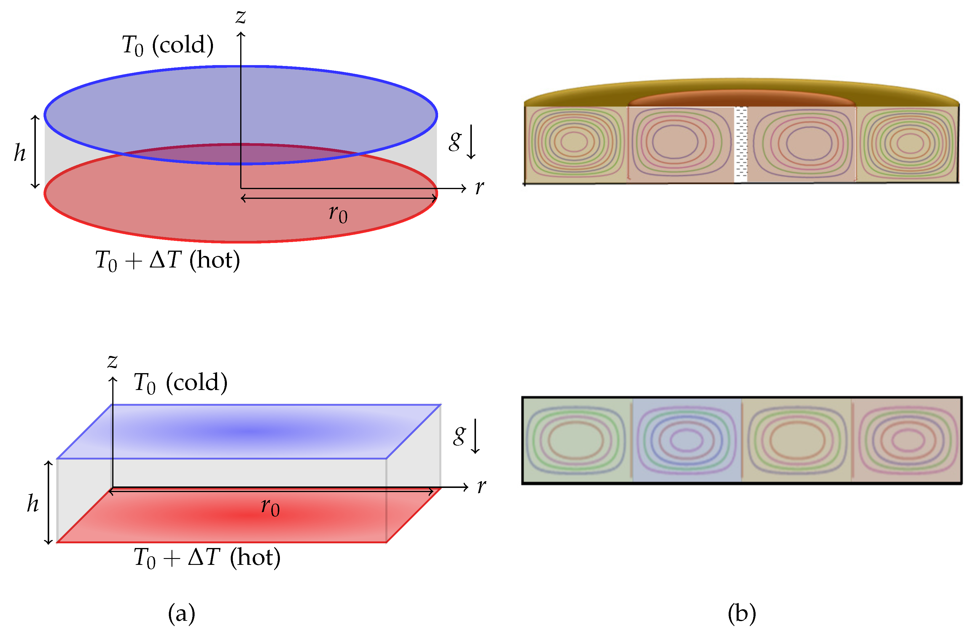
z is taken to be vertically upwards along the axis in the case of a cylinder and along the left wall in the case of a rectangular enclosure. The origin is taken at the bottom of the enclosure(see
Figure 2). To model the problem, we have chosen
with horizontal and vertical dimensions as
and
h, respectively. The vector
represents the two-dimensional velocity field. The temperature field is taken as
, where
t denotes the time. The boundaries of the
are assumed to be impermeable. The lower boundary,
, is maintained at the constant higher temperature,
, compared to the upper boundary temperature of
, where
is the temperature difference. The
cell forms in the system due to the buoyancy effect arising due to the temperature difference between the horizontal boundaries. The lateral boundaries(
in
and
in
) are perfectly insulated.
3. Mathematical Model
The conservation laws(mass, linear momentum and energy) under the Oberbeck-Boussinesq approximation are given by
where
and
. The parameter
in equation (
1) and in
represents the curvature parameter. It assumes the values 1 and 0 respectively in the problems of cylindrical and rectangular enclosures. The quantities
denote the density, the dynamic viscosity, the thermal expansion coefficient, the thermal diffusivity and the acceleration due to gravity, respectively. The term
P in equation (
2) represents the dynamic pressure which shall be eliminated by operating
on equation (
2). This procedure yields the momentum equation in
z-component as:
Here denotes the horizontal Laplacian operator.
In what follows, we shall work with non-dimensional variables
for temperature, velocity, length and time. The scaling chosen for non-dimensionalization of
is
and
. On scaling equations (
1), (
4) and (
3), we get the dimensionless governing equations in the form:
In equations (
5)-(7),
and
. The non-dimensional parameters,
and
, respectively are the Prandtl and the Rayleigh numbers.
Initially, heat transport in the system is only in the form of conduction in the vertical direction. Thus, at the quiescent basic state, the temperature field takes the form .
We now perturb the temperature and the velocity fields with small perturbations and so we take:
.
The above perturbation transforms the governing equations (
5)-(7) to
In equations (
8)-(10), we have omitted the primes for simplicity and the equations are solved subject to the following stress-free, isothermal horizontal and stress-free, adiabatic vertical boundary conditions as mentioned in
Section 2 :
Here represents the aspect ratio. After obtaining the dimensionless form of the governing equations and the boundary conditions, we now proceed to carry out the linear stability analysis in both to find the threshold Rayleigh number at which the onset of convection occurs.
5. Results and Discussion
Analytical study of
in both cylindrical and rectangular enclosures(
) is carried out. The coupled simultaneous equations (
12) and (13) governing the problem are transformed to two decoupled equations each containing the product of three Helmholtz equations(see equations (
19) and (20)). The separable solution of the Helmholtz equation in cylindrical and rectangular
problems include a combination of Bessel and trigonometric functions and purely trigonometric functions respectively. Various range of values of aspect ratio,
, are considered in the study to cover the results of shallow and very shallow enclosures. We now move on to discuss the results of the paper.
The aspects of the axi-symmetric cylindrical problem to be discussed are:
Understanding the nature of convecting cells, the formation of cells, and the need for considering the concept of cell width in the case of not-so-large values of .
Providing explicit information about the connection between the aspect ratio and the number of cells.
In a few articles, the quantity
in equation (
35) is termed as the wave number [
19,
20,
22] and regarding this we have the following observation to make:
For systems with not so large , limited number of convection cells can be seen and hence symmetricity cannot be defined which thereby means that we cannot define a wave number. We will hence have to consider the concept of a cell-width. Hence, in what follows we prefer to use the terminology cell-width when is not so large and the terminology wave number otherwise. we discuss more on this later in this section. Next, we discuss about the procedure followed to obtain the expression for the number of cells in terms of .
5.1. Expression of the critical Rayleigh number
From equation (
36), it is clear that
is dependent on
. For each value of
, the constraint produces different values of
. To determine
it is better to make the substitution
in equations (
35) and (
36). These equations then take the form:
It is known that the constraint (
44) has infinite roots. We name these roots as
). We arrange these roots such that
. For a given value of
,
is not necessarily the value of
p(called
) that gives
. For different ranges of
,
can be
or
or
or
. This information is recorded in
Table 1.
Having obtained
, we may now calculate
from equation (
43) with
p replaced by
. This procedure gives us
At this stage we note that we have just obtained an expression for .
5.2. Plotting of the stream function to have a good idea on the number of cells manifesting for a given
From the tabulated values of
Table 1, intuition tells us that
k actually is the number of cells(see
Table 1). In the analysis that follows, we consider this particular aspect. Having obtained
and
for different values of
, the next task in the paper is to get an expression for the number of cells,
k, in terms of
. To arrive at this expression, we first plot the stream function for different values of
. We know that
where
denotes the stream function. Substituting equation (
27) into equation (
46)(with
replaced by
), and integrating the resulting equation with respect to
R, we get the following expression for
:
where
is an arbitrary constant and the constant of integration does not appear in equation (
47) since the boundary is also a streamline.
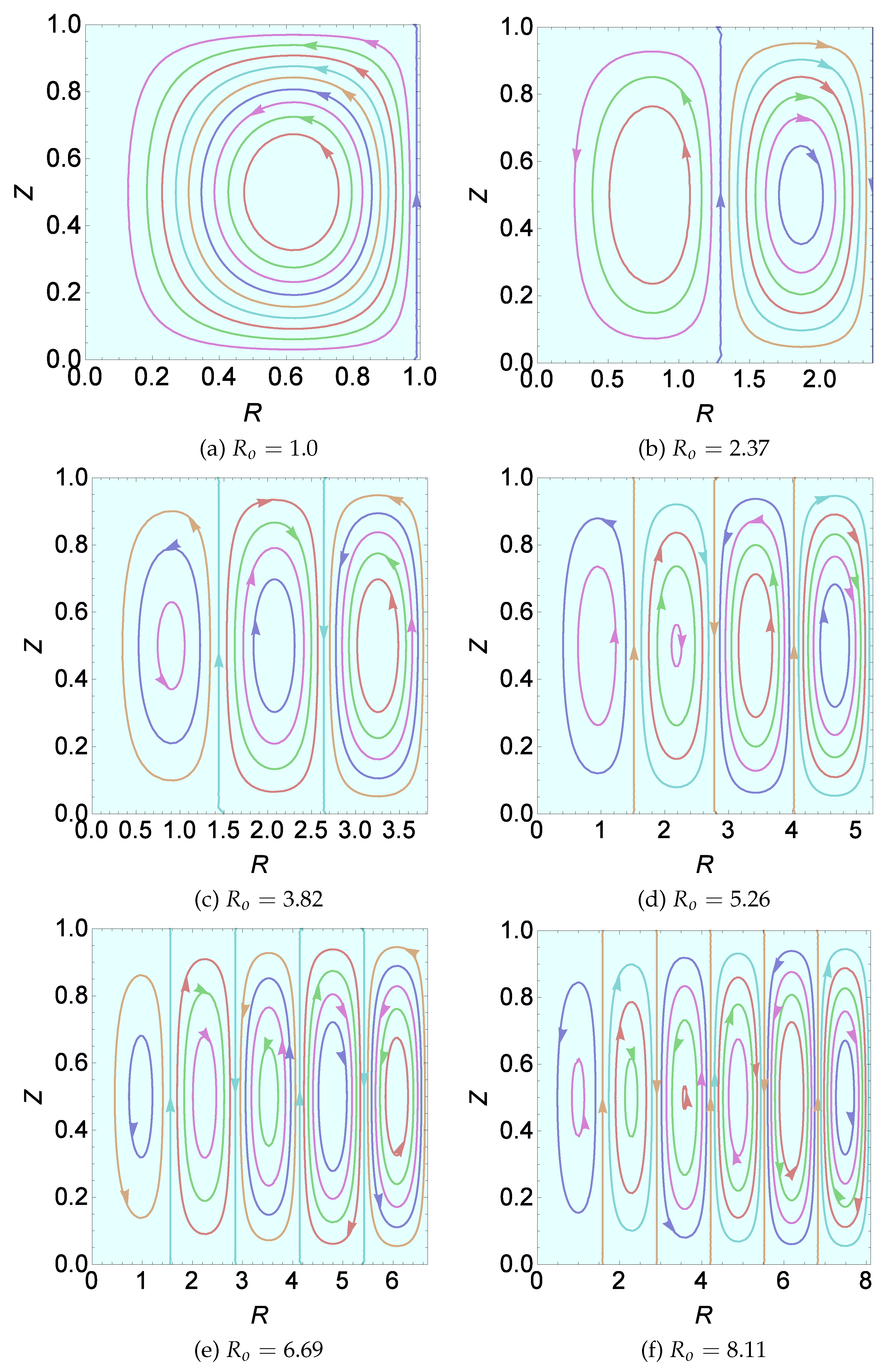
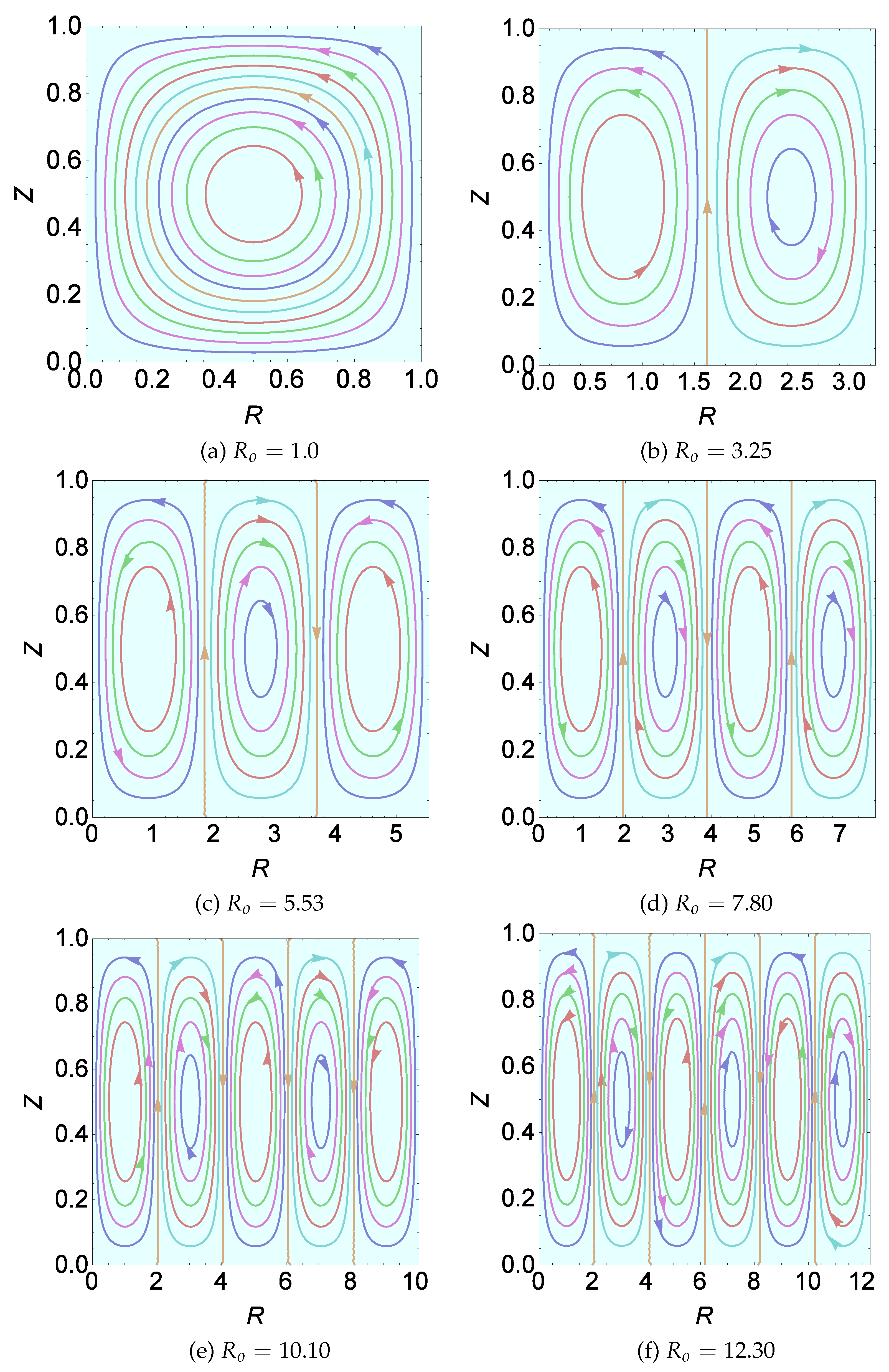
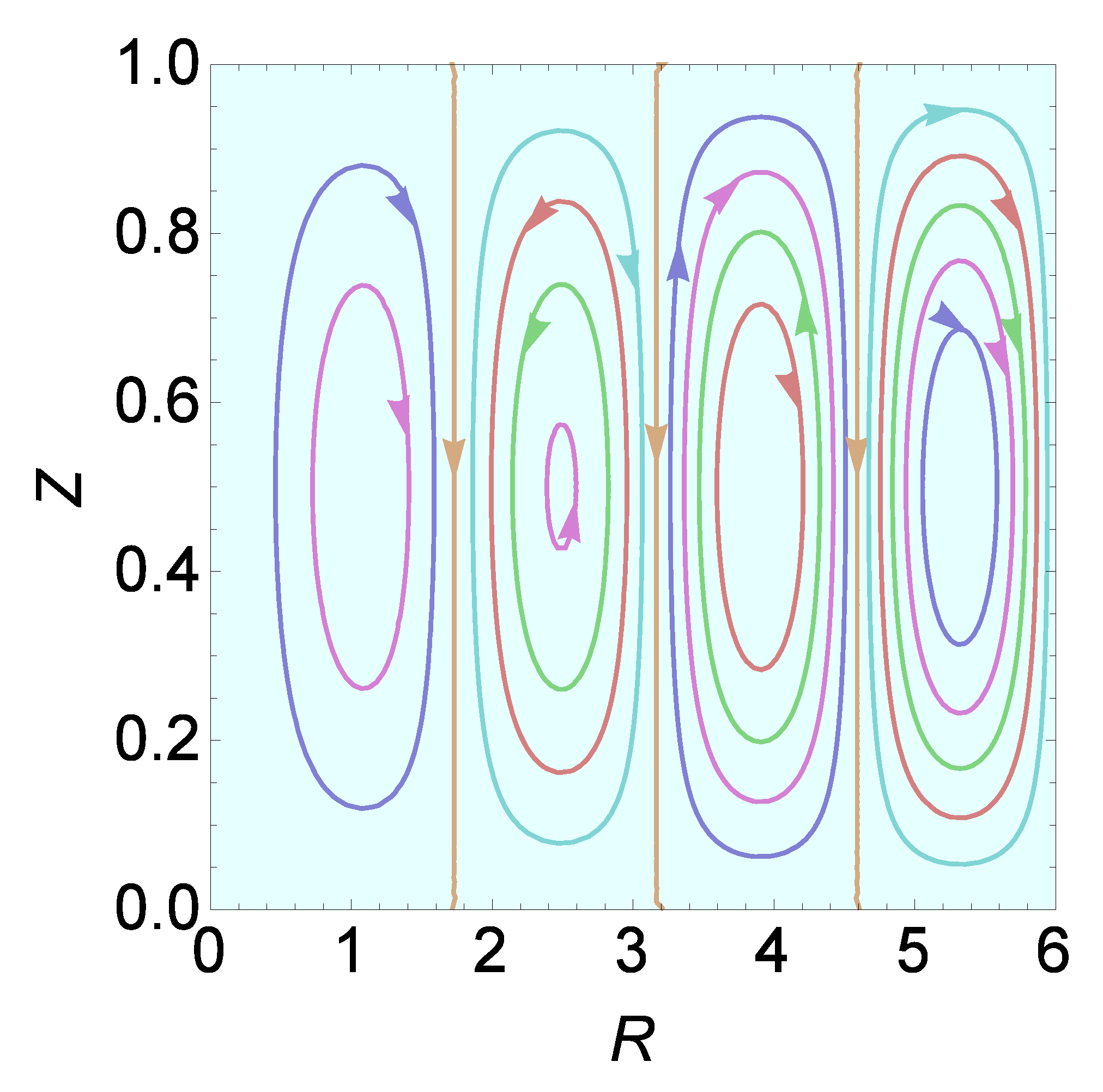
Figure 3 essentially reiterates the results of
Table 1 but with the additional information that
k, in fact, represents the number of cells. For plotting
Figure 3a, we consider a representative value of
. Clearly one cell manifests here. For other values of
within the above interval, it is just one cell that manifests. Regarding this solitary cell we note that it performs anticlockwise circulation. Further, the cell is not equidistant from the axis of the cylinder and its lateral surface. Between the axis of the cylinder and the outermost left boundary of the circulating solitary cell, the fluid is stagnant. This stagnant region is covered by the innermost circular roll. For plotting
Figure 3b, we have considered
. As in
Figure 3a, the first cell circulates anticlockwise while the new cell that forms closer to the lateral surface of the cylinder circulates clockwise. Proceeding further and considering values of
in the remaining four ranges mentioned in
Table 1, we get a sequence of anticlockwise and clockwise circulating cells and the exact number of cells showing up depends on the choice of
. The particular values of
chosen in
Figure 3 are representative values from the six ranges of
mentioned in
Table 1.
Next, we provide some more information on the computations that have been performed. For this we single out the value . In this case too, the cells formed at a distance from the axis with the first circulating cell being anticlockwise, the second being clockwise and the other cells circulating in alternate directions as we move towards the lateral surface of the cylinder. An important observation, however, from the computation done in the paper is that the first cell stands out as being different from the other cells. Except the first cell, we observe a symmetry in the horizontal dimension of the other cells. The vertical dimension of the other cells, however, differ from each other. It was found that as increases, the height of the cells increase with the tallest found close to the lateral surface of the cylinder. Yet another observation that can be made in regard to the formation of the cells is that beyond the first cell(for ) increase in the number of cells happens for an increase approximately by 1.42 in . This estimation gets accurate for values of .
5.3. The concepts of cell-width and the wave number
In the discussion that follows we consider two ranges of values of :
-
(not very shallow cylindrical enclosures):
For these cylindrical enclosures, we find that there are finite number of cells whose structure is very much different from each other and hence symmetricity cannot be observed between the cells. Thus, the concept of wave number is inapplicable. In these situations, we will have to make use of the concept of the cell-width which is essentially the width of one cell.
-
(very shallow cylindrical enclosures):
In these enclosures, the cells structure seems more or less symmetric to the classical rectangular
cells except for the first cell that forms around the axis of the cylinder but at a distance from the axis. In this case, we note that there is a finite cylindrical space around the axis in which the fluid is static(stagnant zone or no-cell zone). Just next to this static zone, convective activity is seen. The width of this first convective activity is different from the structure of subsequent cells that form when we increase
. Even though we have noted that the cylindrical
cells are similar to the rectangular
cells when
is large, it is extremely important to note that there is one fundamental difference. We can easily observe that the height of the cylindrical
cell is least near the axis of the cylinder and takes a maximum height in a region very close to the vertical curved surface of the cylinder. Yet another important observation we have made is that the width of the first cell is always not equal to that of the other cells. This is in contrast to what we observe in the case of rectangular
wherein cells that form are such that they are of the same size(see
Figure 4).
From the above proceedings we next consider the following evident aspects of cylindrical :
For not so large values of we cannot use the concept of wave-length. We will have to make use of the concept of a cell-width.
In the case of very large , however, the concept of wave number applies but only in regions beyond the first cell.
For very large wherein the concept of wave number applies, when we refer to one wave-length we refer to a pair of counter rotating cells and in the case of small/moderate values of , the cell-width refers to the horizontal dimension of one cell. An other important point to always remember in the case of the considered cells is that the concepts of cell-width, wave-length and wave number, whichever is applicable, are concepts that have to do with the horizontal dimension of the cell and not on the vertical dimension of such a cell. It is well known that at large values of the aspect ratio the axi-symmetric convection breaks down. In this case, the results of shall be obtained from the classical problem.
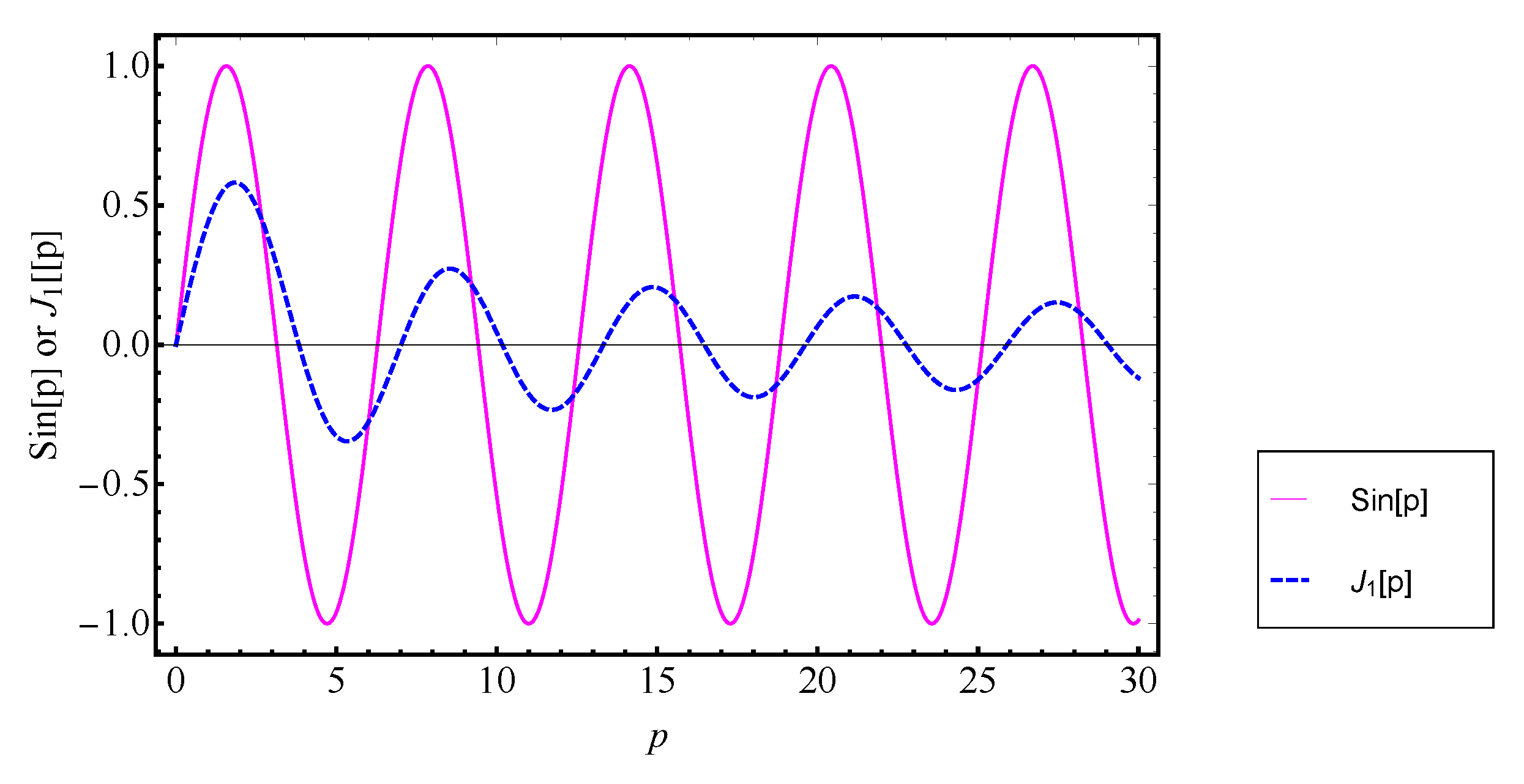
From the procedure outlined earlier in the case of the cylindrical , for the finding of the critical Rayleigh number, , it is apparent that compared to the problem of rectangular , the cylindrical problem involves a combination of Bessel and trignometric functions as the eigenfunction. Further, is obtained by using a constrained extremisation approach like in the case of the rectangular problem. The constraint in the case of rectangular involves while the cylindrical case involves . It is important to see the plots of and versus p in order to further understand the difference between the two problems.
Figure 5.
Plot of and versus p.
Figure 5.
Plot of and versus p.
The periodicity of the function is but we cannot define the same while dealing with Bessel functions since the wave-length, , depends on the range of under consideration. Increase in the value of results in a decrease in the value of the wave-length and also decrease in its amplitude. Such decreases in the wave-length happen only upto two pairs of counter-rotating cells. Beyond the 2nd pair of counter-rotating cells, we observe that becomes a constant, for values of . The amplitude, , however, is such that . One more observation that can be made is that after every completion of a cycle by the constraint function , there will be appearance of an additional cell opposite in sense to the previous cell. This happens continuously in all range of values of . Yet another observation that we can make is that in the range of values of wherein the crest of the constraint function appears, we see one counter-rotating cell. Likewise we see clockwise-rotating cells in the trough region of such functions. This is true for both cylindrical and rectangular problems.
The points at which the curve crosses the axis gives us its root which is related to . Hundred roots of were calculated to see if we could come up with some new observations. We found that nearly for (after the second cell). This observation is in line with our findings on the nature of cells. We had mentioned earlier that cells beyond the second cell are symmetric in its horizontal dimension. This observation most importantly confirms that , in fact, is the cell-width.
We next focus our attention on enclosures with moderate/large values of
. Our intention at this point is to find an analytical expression for the
as a function of
k. This information is presented as tabulated values in
Table 1. In order to find the expression of
, we tried to fit a linear interpolation curve on the data of
Table 1. The formulae that came to mind in obtaining the line of best fit are
where
. As observed earlier, there is symmetry in the structure of the cells beyond the first-cell and hence quite expectedly the third function and onwards were found to be the lines of best fit. Though the fourth function and those beyond it produce least errors in the expression of
for large values of
compared to the third function, but these functions had large errors in them for smaller values of
. Hence we have chosen
as the line of best fit. On substituting
from equation (
48), it was found that
, while the roots of
reported in
Table 2 were found to be
. This information is recorded in
Table 2. This table indicates the difference in the accuracy of the zeros of
obtained numerically and by the derived formula. The roots given by equation (
48) and the actual roots of
, for different values of
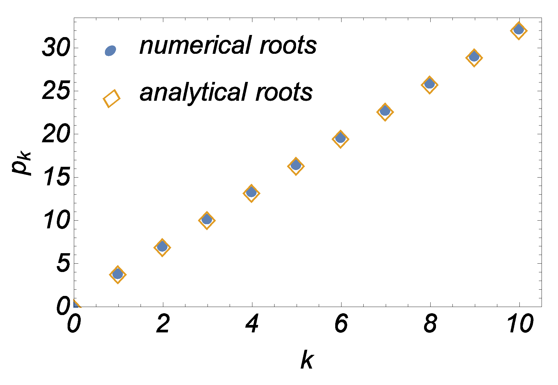
k, are plotted graphically in
Figure 6. The figure clearly shows that the roots obtained from the formula (
48) and the actual roots of
(obtained numerically) coincide upto three decimal digits and is good enough for our purpose as shown in
Figure 6.
5.4. Expression of the number of cells and the Rayleigh number as a function of the aspect ratio
On substituting
of equation (
48) in the place of
p in equation (
43), we get
We know from
Table 1 that
k depends on
and that over a range of values of
,
k remains the same. For example, for
we have
, and likewise for
we have
and so on. This exact dependency of
k on
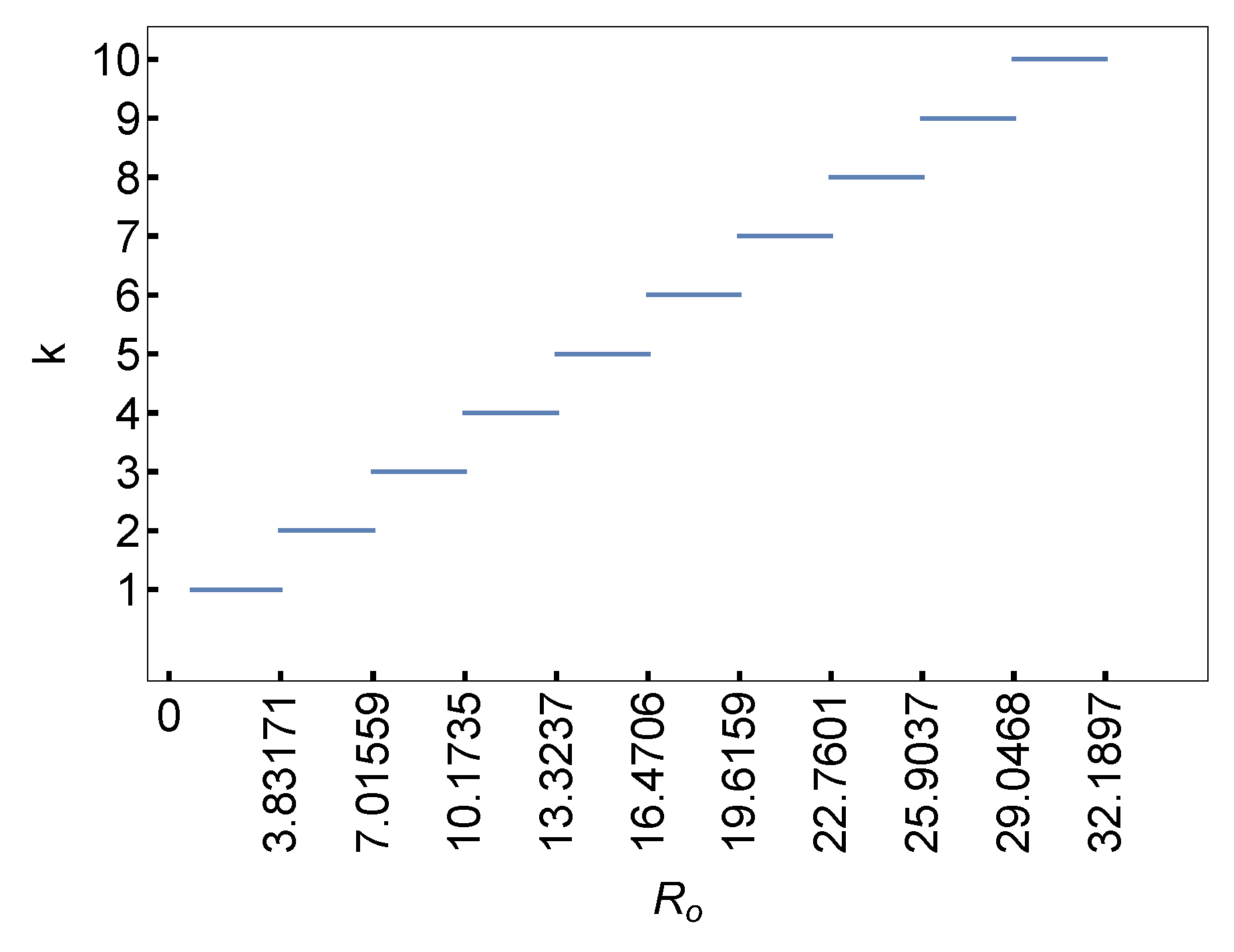
is represented pictorially in
Figure 7.
Using equation (
49), we can determine
. A little explanation is required as to how exactly
is calculated. From
Table 1, we can extract information on
k for a given value of
and this yields us
for that assumed value of
. This procedure is followed for each value of
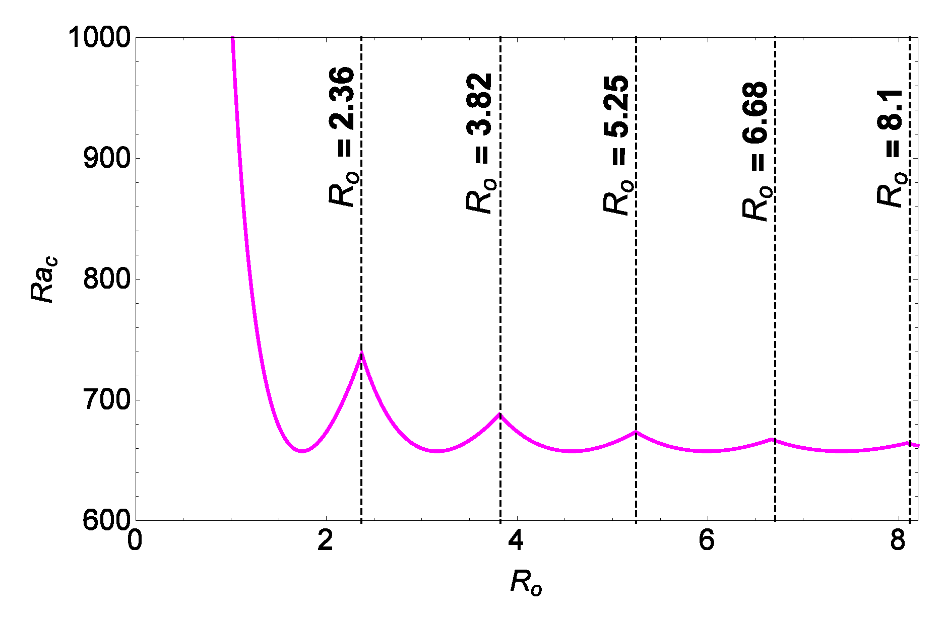
. Such a plot of
as a function of
is presented in
Figure 8. The intersection points of the various marginal stability curves in
Figure 8 provide information to us on the increment by 1 to the number of cells. Up to the first intersection point, the number of cells that manifest is one. From the first intersection point to the second, the number of cells that appear is 2. One can similarly make conclusion on
k for the remaining values of
. The intersection point between two consecutive marginal stability curves give us information not only about what is documented in
Table 1 but also provides vital information on the exact dependency of
k on
(piecewise linear dependency as seen in
Figure 7). To determine such an intersection point, we consider
On solving the equation (
50) for
k we obtain a 7
th degree polynomial equation whose real root helps us in determining the number of cells. The relationship between
k and
may now be written by noting the following facts:
On making use of the above 2 bits of information, the explicit expression of
k in terms of
can be obtained as a root of the polynomial equation as
where
In equation (
51),
is the ceil function of
. We note here that the ceil function is a function which returns the smallest integer greater than or equal to
. The term
is the Kronecker delta function which returns 1 when
is equal to zero and returns 0 otherwise. The value of
k gives the number of cells.
While obtaining
from equation (
49), we have to determine
. With
k as a function of
being explicitly known now through equation (
51), we may directly determine
for a given
without seeking recourse to
Table 1. So we now write
where
k is given by equation (
51). With this definition of
, the expression of
, from equation (
49), is now written as
5.5. Expression of the wave number in a very shallow enclosure
Recalling that
, we may, on using equation (
53), write it as
This definition is obviously applicable for very shallow enclosures and is the expression of the critical wave number. As noted earlier the symmetry in the structure of the cell is observed beyond the 2
nd cell. The radial distance between the axis of the cylinder and the edge of the 2
nd cell is
. All pairs of counter-rotating cells after the 2
nd cell have approximately the wave-length of
. The exactness of the representation of the wave-length improves if we take
large enough.
Figure 9 is the plot of streamlines in the region
. The
Figure 9 clearly shows that the region
includes the stagnant zone and the first counter-clockwise rotating cell. The region
represents the wave-length. Expectedly, for very large values of
the boundary effects(curvature effects) become negligible and hence in that case
converges to the value
which is the wave number of the classical rectangular
problem. In this case,
.
We next discuss aspects of the two-dimensional rectangular problem similar to those of the cylindrical counter part.
5.6. Results on the rectangular problem
Following the procedure of the cylindrical
problem, we now present the results of the rectangular
problem. The stream function in this case is given by:
The relation connecting the number of cells and the aspect ratio in the case of the rectangular
is:
where
In equation (
57),
is the ceil function of
and
is the Kronecker delta function. The value of
k represents the number of cells and this then determines
.
We next present the similarities and the differences between the results of the cylindrical and rectangular problems.
5.7. Similarities and differences between the results of the cylindrical enclosure and the rectangular enclosure
Though the two geometries are different they possess many similarities. Some of them are
The wave number as well as the critical Rayleigh number of both and for are almost equal to and respectively.
Each new Rayleigh-Bénard cell( cell) in always appears close to the lateral boundaries(right lateral boundary in ).
A new cell forms in with an approximate increase of 1.42 in the value of .
Differences between the results of the two problems are:
The eigenfunctions in the case of are always trigonometric while in the case of , they involve Bessel functions as well.
The rolls are straight in while they are circular in .
In cylindrical cell there exists a stagnant region and the same is not seen in the case of .
Due to the presence of a stagnant region, the dependence of the number of cells on the aspect ratio is not the same in the cases of and .
As the value of is increased, the horizontal dimension of the streamlines does not change while the vertical dimension gradually increases towards the lateral surface of the cylinder. In the the cell aspect ratio is always fixed while it is not so in .
Critical values of the wave number and Rayleigh number are not the same in the cases of and for small/moderate values of .
