1. Introduction
Despite all performance enhancements to IC electronics and micro-fabrication, quartz crystal oscillators and surface acoustic wave devices are commonly used in transmitters and receivers of wireless architectures [
1,
2,
3,
4,
5]. These components are widely spread in microelectronic markets due to their excellent and important performance properties [
6,
7,
8]. One of these properties is low impedance characteristics which are strongly preferred in constructing low insertion loss filters and low phase noise oscillators [
9]. Also, the quartz resonators have a high-quality factor that strongly supports their market’s acceptability. A high resonator quality factor reduces phase noise in oscillators [
10,
11] and enhances the filter selectivity [
12,
13].
These intrinsic qualities make for decades of searching for other oscillating devices, not success. The drawbacks of quartz oscillators are their large size and the impossibility of being fabricated with the electronic device at the die level [
14]. To solve this drawback microelectromechanical systems (MEMS) strongly introduce themselves as a suitable substitutional to quartz oscillator [
15,
16]. The basic concept of micromachined resonators, mechanically vibrating structures are electrically sensed [
17]. MEMS resonators attract interest in sensing applications, where changes in the frequency of resonant bodies are used to monitor certain quantities. Also, in timing applications, when a resonant plate is connected with an electronic circuit to build a clock signal with excellent properties or in transmitters and receivers of radio frequency wireless devices [
18].
MEMS resonators are demanded to be the main source of frequency generation in these applications due to low-cost batch fabrication [
19]. Also, it has the possibility for fabrication and integration with microelectronics at the die or package level [
20]. These advantages lead to reduced cost and form-factor of the systems. Beyond all these advantages some limitations are still totally unfixed. Some of these limitations are material loss, temperature instability [
21], anchor loss, surface loss, ohmic loss, and capacitive loss. The main loss is anchoring loss which is defined as the loss of energy due to the propagation of acoustic wave from the resonant body to supporting anchors. One way to save this energy is by adding an acoustic reflector [
22]. The limitation of this technique is the reflector is not efficient in reflecting acoustic waves [
23]. Another way is to implement one or two-dimensional phononic crystals at the anchors of the resonator or in supporting tethers which are widely done by groups of researchers, and the difference in the effect of PnC structure to reflect acoustic wave by generating wide bandgap [
24]. The third way is to mechanically isolate the vibration between the resonant body and anchor boundaries by adding a suspended frame between the anchors and the resonant body [
25]. In this article, a new tether design built on the principle of force distribution/unit area is proposed to minimize the transmitted force to anchors and as a result, enhance stored energy in the resonant body and anchor quality factor.
2. Nonconventional Tethers Mechanism
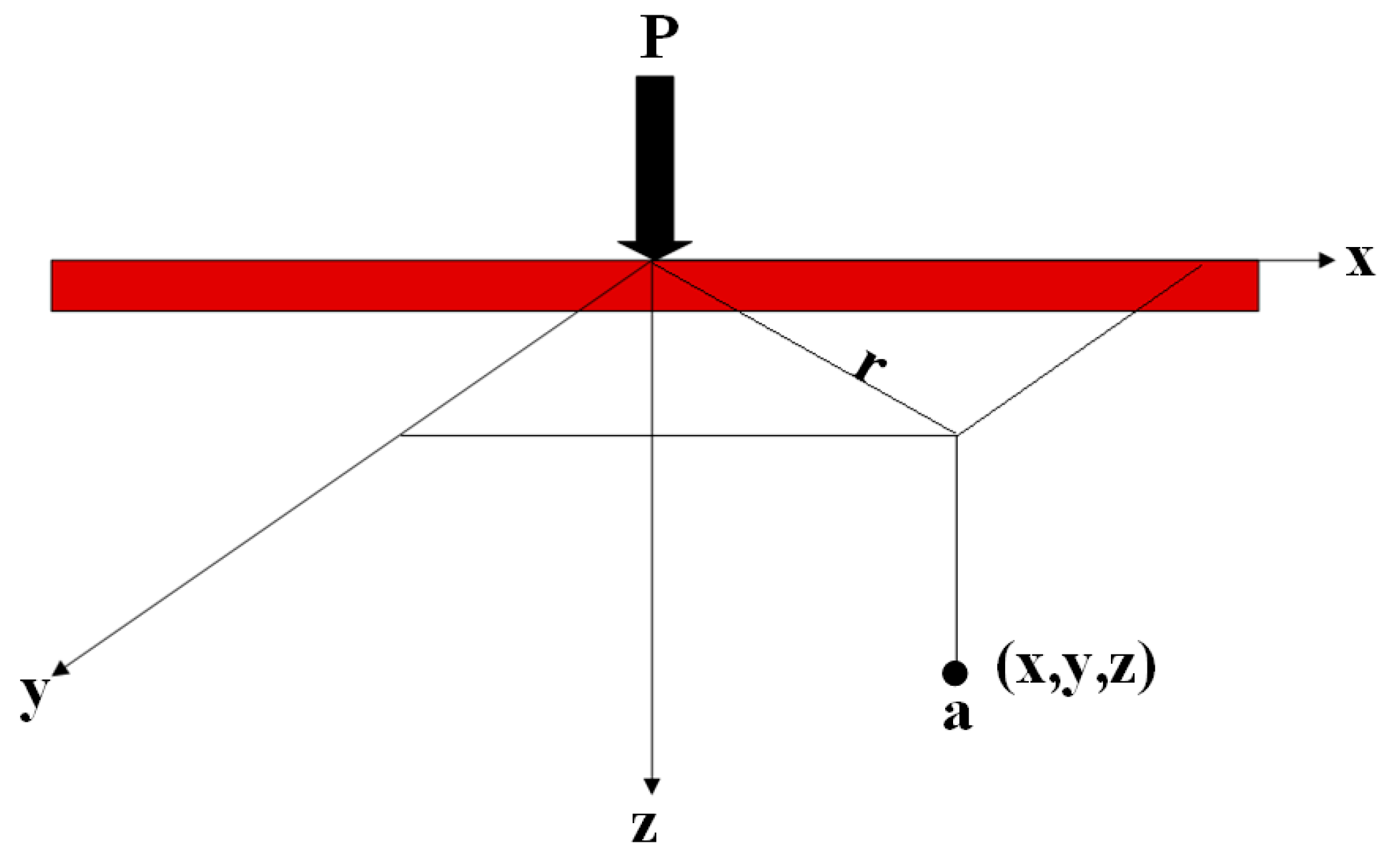
A new structure (TWHL) is applied on the MEMS resonator support tethers. The concept of the new design is belt on force distribution on the surface area. The force applied on anchor boundaries will be distributed along the three tether legs before reaching the anchors, resulting in a decrease in mechanical damping and quality factor enhancement. The mathematical relation for calculating the shear and normal stress inside elastic, isotropic, and homogenous mediums due to force applied at the surface was developed by Boussinesq in 1885, as shown in
Figure 1. According to this relationship, the stress at point (a) due to the force of magnitude P is given by [
26]:
where Δσ represents stress at point (a), P represents applied force
, and x, y, z represents coordinates at point (a) as shown in
Figure 1.
As shown in
Figure 1 an infinite line load length has stress/unit length (
q/l) on the surface of elastic material. The vertical stress, Δσ, inside the surface at point (a) can be calculated using the theory of elasticity, or
This equation can be rewritten as
Hence Equation (4) is in a non-dimensional form. the calculation of the variation of Δσ/(q/z) with x/z can be obtained using this equation. The value of Δσ obtained from Equation (4) is the additional stress on the surface caused by the line load.
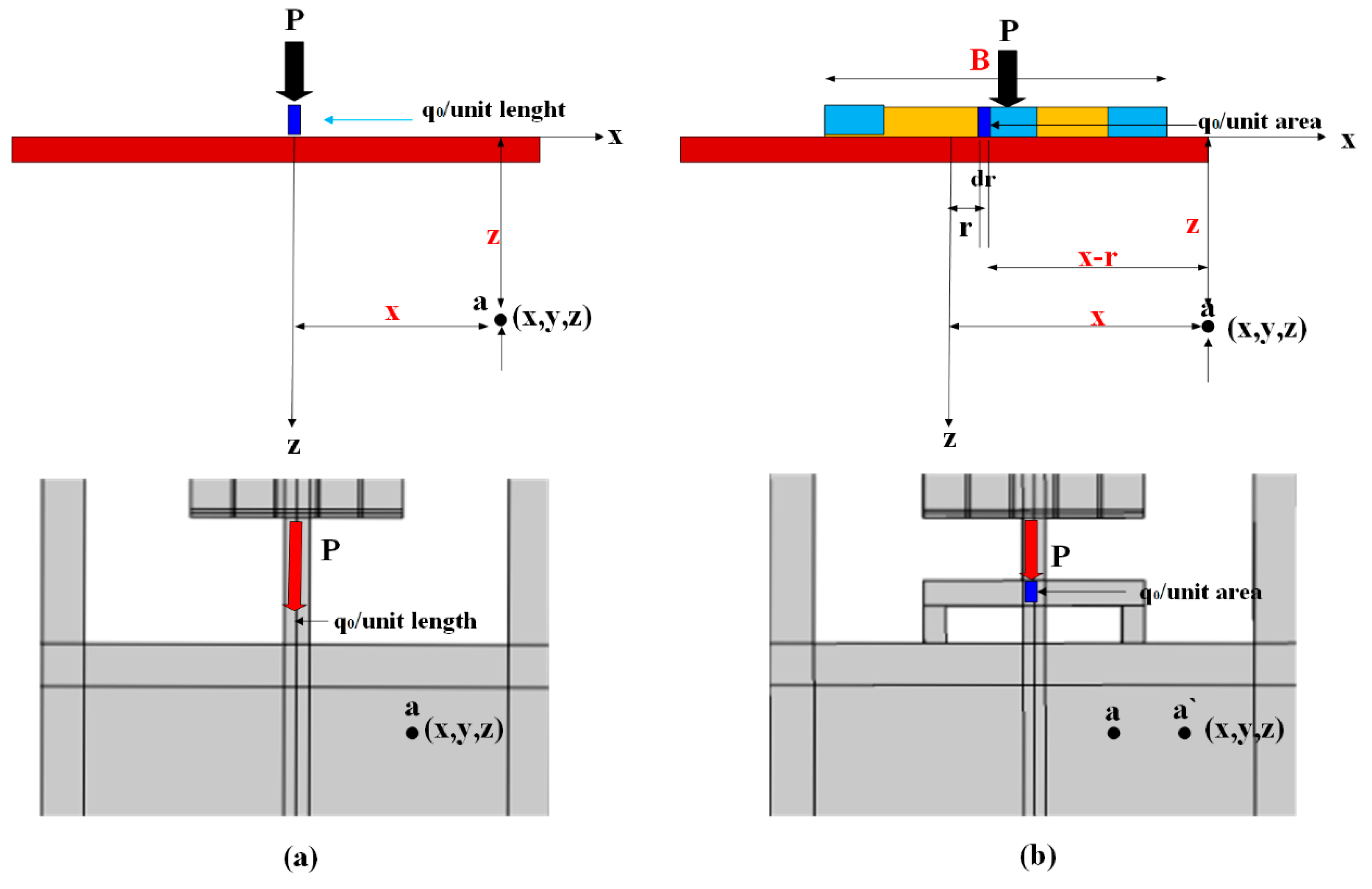
Figure 2a represents the stress applied on anchor boundaries through the tether length (q/unit length). The stress applied in
Figure 2b is distributed over the new design area (TWHL) if the design length is l and width is B, so the stress applied on the anchor is equal (q/BL) which is less than the stress on line load (conventional tether). To prove the stress applied on anchors is lowered due to the TWHL tether, use Equation (2) to calculate the stress inside the surface width B. Assume a strip with force (
qo per unit area) as shown in
Figure 2b. Consider an elemental strip of width
dr, the force per unit length of this strip is equal to
qo dr. This elemental strip is considered a line load. Equation (4) gives the stress Δσ at point (a) inside the surface caused by this elemental strip load. To determine the stress, substitute qo dr for q and (x-r) for x. So,
The stress Δσ at point (a) caused by the given strip force of width B can be calculated using the integration of Equation (5) with limits of r from -B/2to +B/2, or
Concerning Equation (6), the following should be considered:
are in radiance, the magnitude of Δσ depends on x/z, equation is valid if x ≥ B/2, however for 0 ≤ x ≤ B/2 the magnitude of becomes negative. In this case, it should be replaced by
To calculate the value of stress at point (a) due to applied load P on the resonator,in this work B=125 μm at point (a) x=50 μm and z=100 μm, and solve Equation (4) to obtain the value of stress. Since x=50 < B/2 = 62.5 μm, and q
0 represents stress/unit area applied on tether leg. Equation (6) can be rewritten as [
26]:
Substitute in the equation
Hence,
, so
, the stress on point (a) lower than the applied stress on the tether legs by 50%. This verify the amount of stress force transferred to anchor boundaries was lowered due to the desired TWHL tether design. similarly at point (a`) x=100 > B/2 = 62.5 μm, substitute in Equation (6) as follows:
, so , the stress on point (a`) is lower than the applied stress on the tether legs by 24%. The two examine points in and out plan of new tether design proved the ability of the new design to reduce the stress force transferred to anchors resulting in energy stored enhancement.
3. Nonconventional Tethers Transmission Characteristics
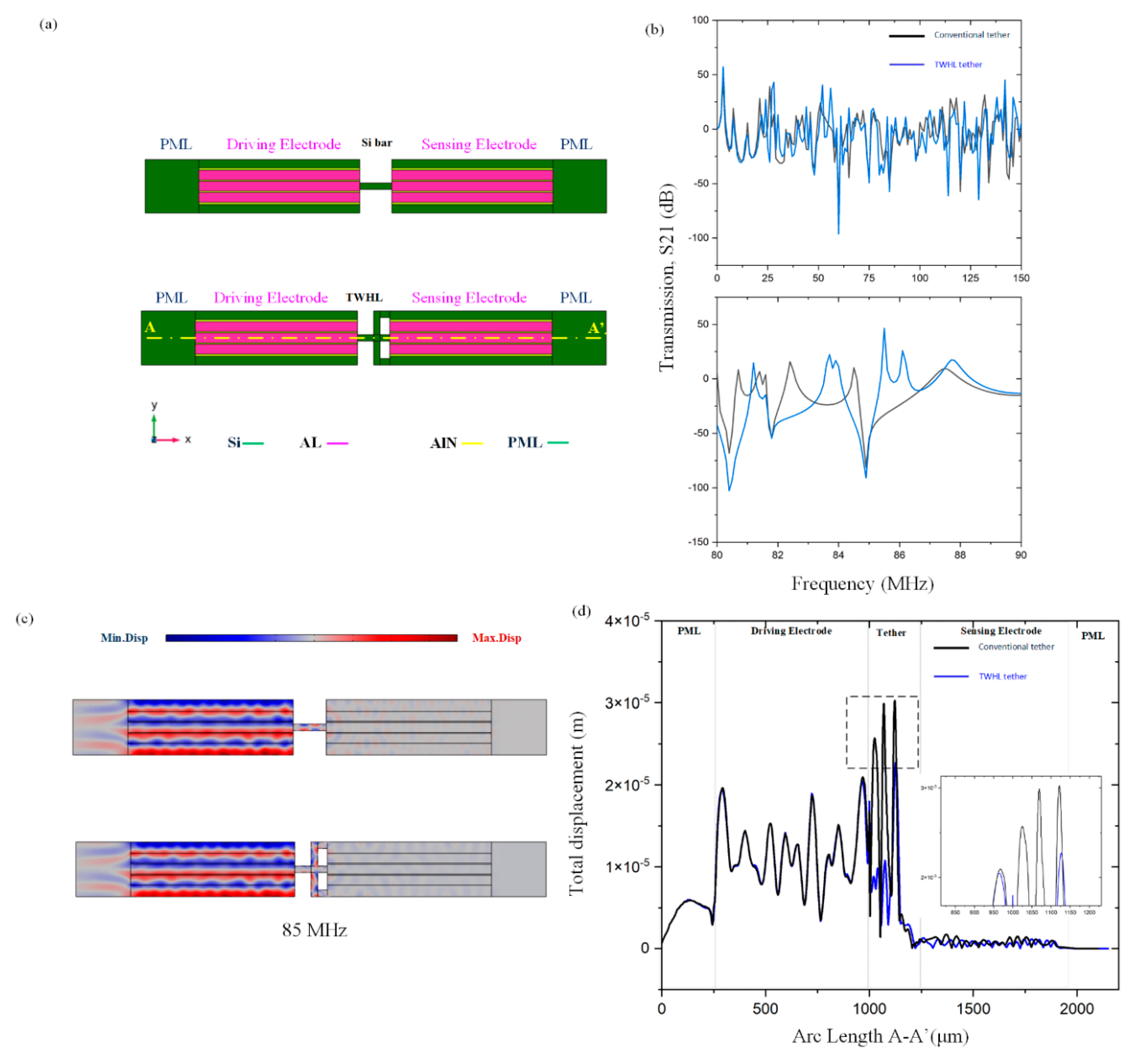
To verify the acoustic wave energy transmission attenuation through the nonconventional tethers, two transmission lines were designed between the resonant body and anchor boundaries. The first one is a silicon bar and the second one is (TWHL), as shown in
Figure 1.
Figure 1b shows the TWHL structure has a lower transmission than the silicon bar, resulting in energy transfer attenuation. However, TWHL shows higher attenuation in the tether section compared to the conventional tether. The drive electrode is excited by 0.01 watts and sense electrodes are set to 0.0 watts. The transmission (S21) is calculated by [
27,
28,
29,
30,
31]:
where P
in and P
out represent the amplitude of input and output power in the two transmission lines. The displacement distribution in the resonant body with two delay lines is shown in
Figure 1c. S21 represents the input-to-output port power transmission coefficient. Clearly from
Figure 1 d at 85 MHz the displacement profile for the delay line with TWHL shows strong attenuation to displacement than the silicon bar as they were used as two transmission mediums on the A–A’ line. The finite element simulation results prove that the wave is strongly attenuated in the transmission spectra at the beginning of the TWHL tether design and continues to zero, compared to the conventional tether. TWHL satisfies that there is strong prevention of propagation of acoustic waves.
Figure 3.
(a) 3D illustration of silicon bar and TWHL (b) transmission characteristics of silicon bar and TWHL (c) Displacement distribution of the delay line with silicon bar and TWHL as two transmission medium (d) displacement profile at 85 MHz frequency for the two delay lines on the A–A’.
Figure 3.
(a) 3D illustration of silicon bar and TWHL (b) transmission characteristics of silicon bar and TWHL (c) Displacement distribution of the delay line with silicon bar and TWHL as two transmission medium (d) displacement profile at 85 MHz frequency for the two delay lines on the A–A’.
4. Resonator Design
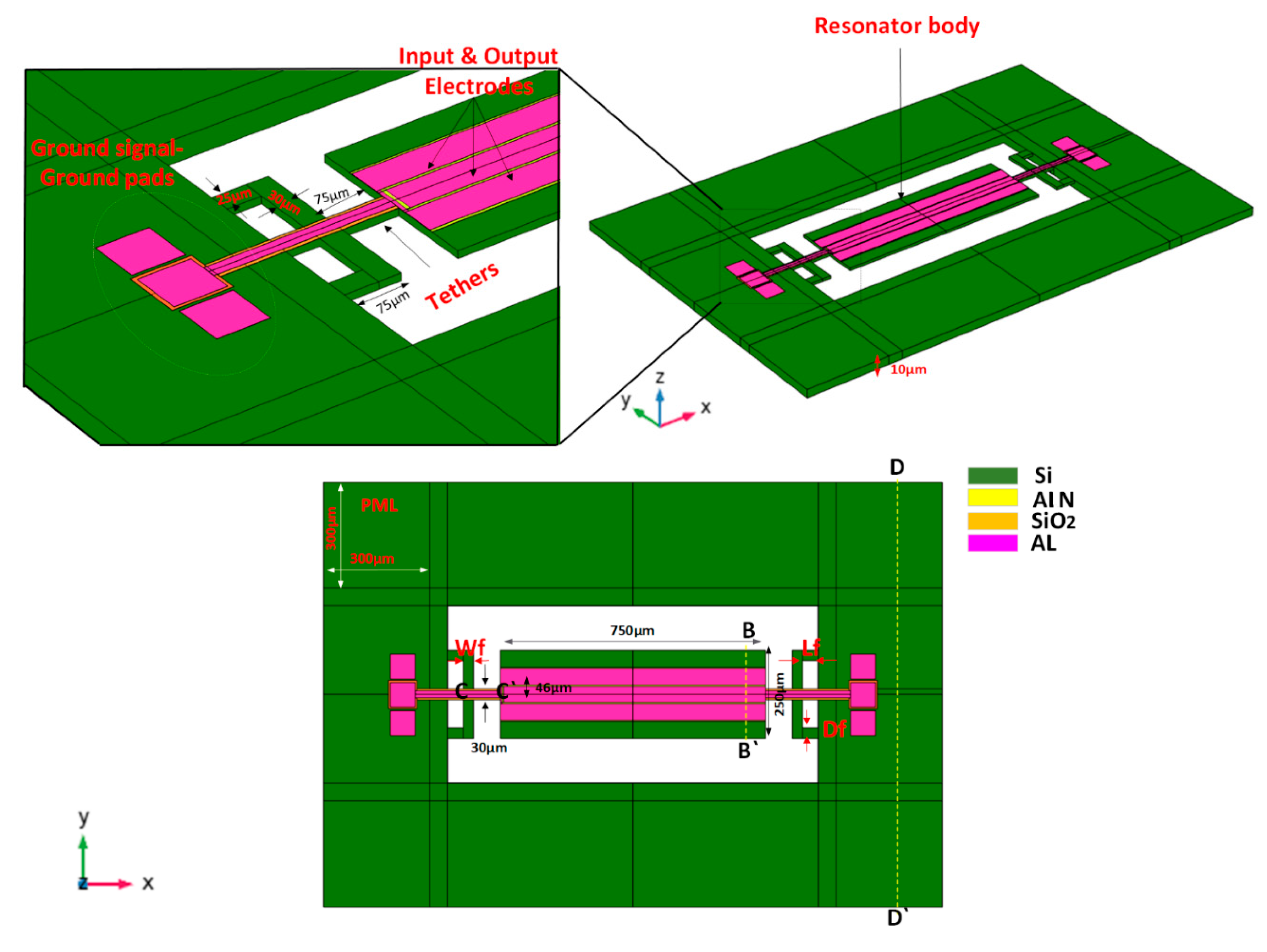
A 5th-order width extension mode resonator is designed and simulated using COMSOL Multiphysics through the finite element analysis method. As shown in
Figure 4 a thin layer (AlN) of 0.5μm thickness, width, and length of 150μm and 750μm is placed on top of the silicon substrate. The dimensions of the resonator are 250μm width and 750μm length respectively. The depth of the Al electrode is equal to 0.5μm, width and length 46μm and 750μm respectively, and the distance between the two electrode center lines is 50μm (i.e., electrode gap=4μm). The electrode excites the vibration on the resonant body by applying 1V on the piezoelectric material. The wavelength of the resonator λ is equal to 100μm. The dimensions of the TWHL are Lf=45μm, Df=25μm, and Wf=30μm as shown in
Figure 4. The
fr of the resonator can be calculated using the formula [
32,
33,
34,
35,
36,
37,
38]:
Where
v represents the velocity of the acoustic wave 8500 m/s, n represents the mode number equal to 5, and w represents the width of the resonator. The resonant frequency (f
r) calculated from Equation (10) is ≈ 85 MHz in the desired design
w=250 μm. The resonator design parameters are illustrated in
Table 1.
5. Resonator Mode Shapes
A three-leg tether (TWHL) is applied in the tethers of the MEMS resonator to enhance the anchor quality factor and attenuate the energy leakage, and at the end enhance the total quality factor (Q
tot). The Q
anchor of the TPoS MEMS resonator can be obtained generally from the resonance frequency divided by the -3dB of bandwidth of the resonance maximum peak in the displacement profile at frequency response as [
39,
40,
41]:
Where
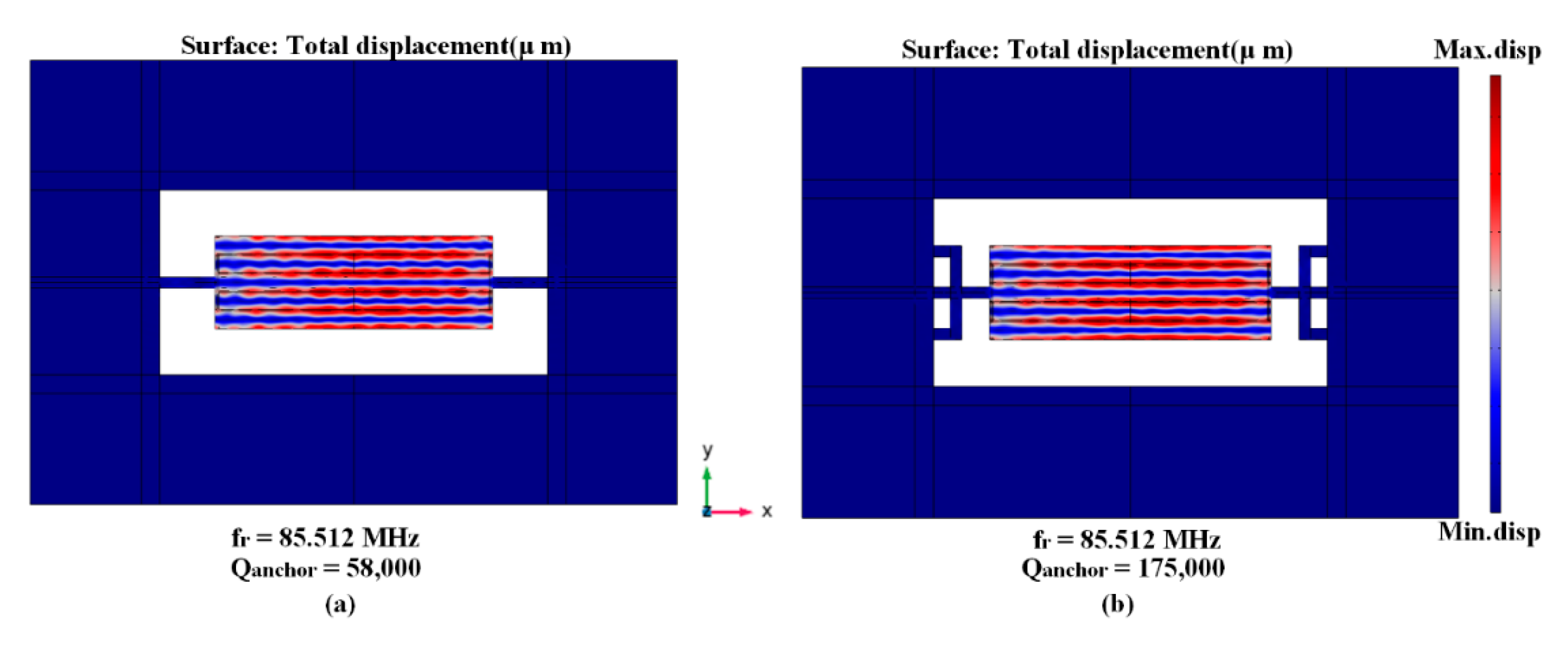
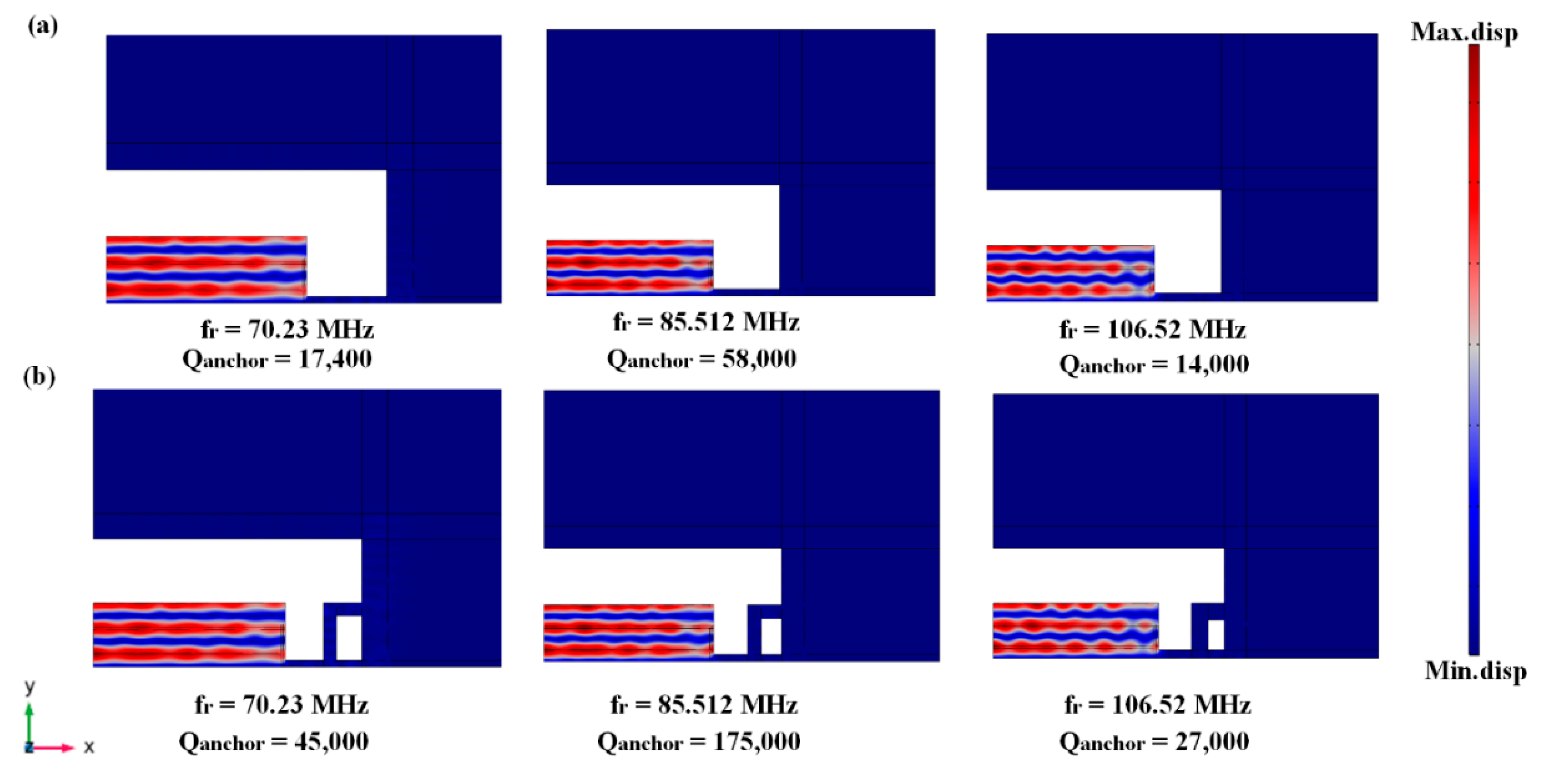
fr is defined as resonance frequency, the anchor quality factor obtained from conventional tether is equal to 58,000, while the anchor quality factor of TWHL is equal to 175,000 providing 3-fold enhancement. The resonator mode shape with conventional tether and with (TWHL) and associated anchor quality factor are shown in
Figure 5.
6. Discussion
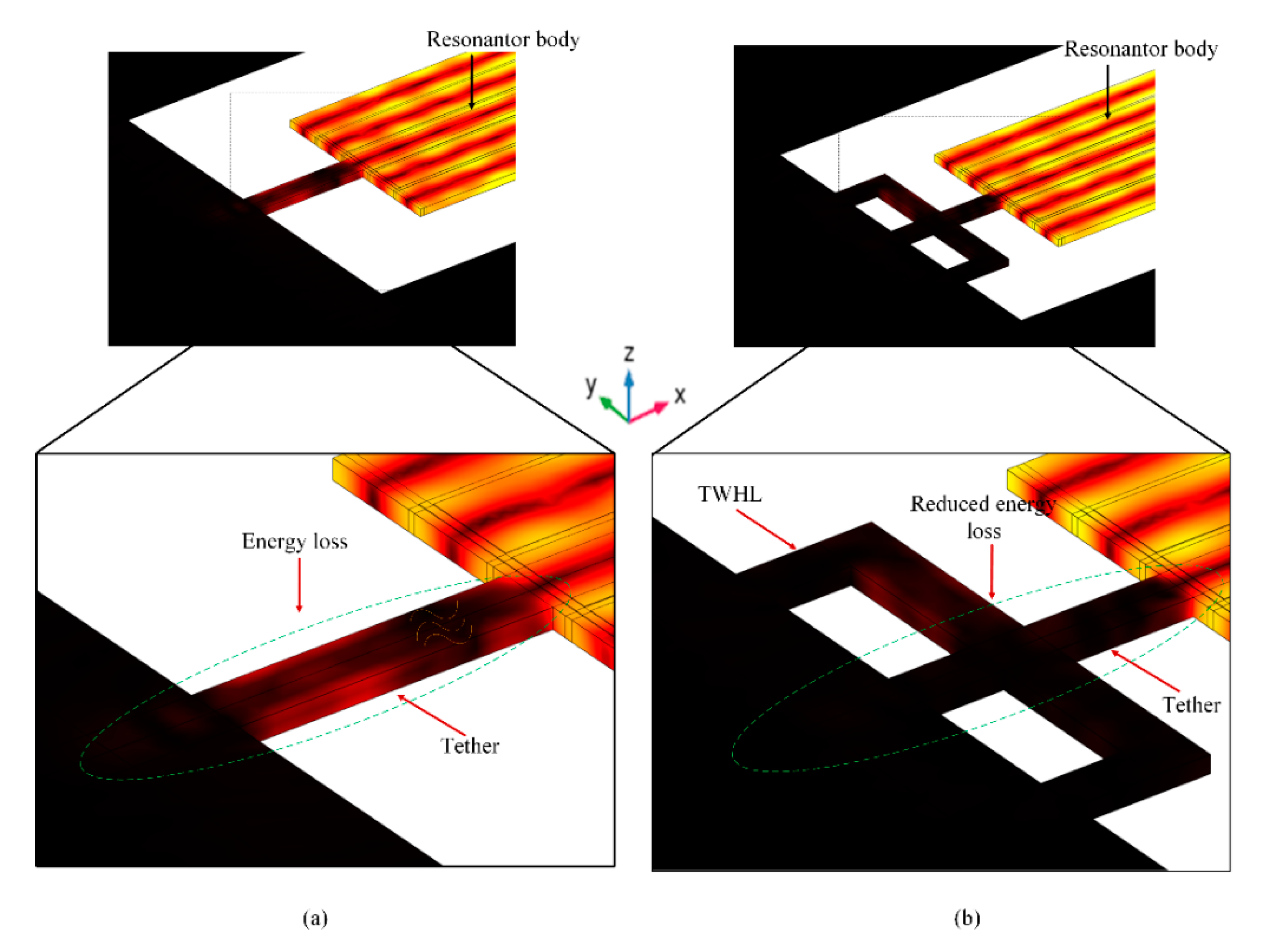
The energy distribution of the bulk acoustic wave in conventional tether and TWHL is shown in
Figure 6a,b. In conventional tether the amount of energy escaped from resonant body is greater than the proposes design (see
Figure 6a). The light brown color in the figure shows the energy transferred from the resonant body to the supporting anchors. Adding the TWHL tether decrease the amount of loss energy and increase the stored energy in the resonant body (see
Figure 6b) the light brown color represents the amount of energy leaked to the supporting anchors which is clearly less than the conventional tether.
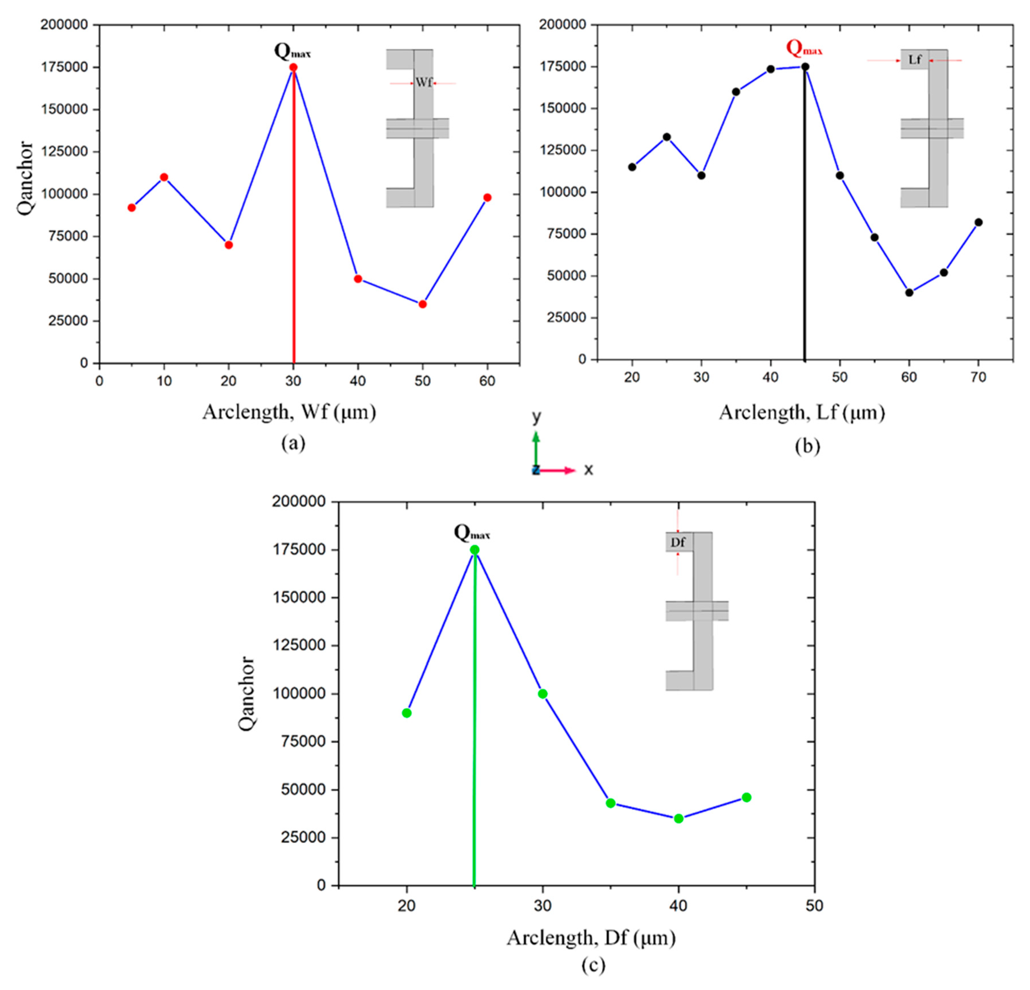
Different values of anchor quality factor according to change TWHL dimensions (i.e., Df, Wf, Lf) is obtained as illustrated in
Figure 7a–c. The branch Wf is swept from 5 μm to 60 μm, the maximum Q
anchor obtained at width 30 μm. The length of TWHL tether in x direction is changed from 20 μm to 70 μm, the minimum value of the anchor quality factor is obtained at the Lf=60μm, while the maximum Q
anchor at Lf=45 μm. The depth of the TWHL in y direction is swept from 20 μm to 45 μm, while Wf, Lf is set to 30 μm and 45μm respectively. The maximum Q
anchor at the values of Df=25 μm.
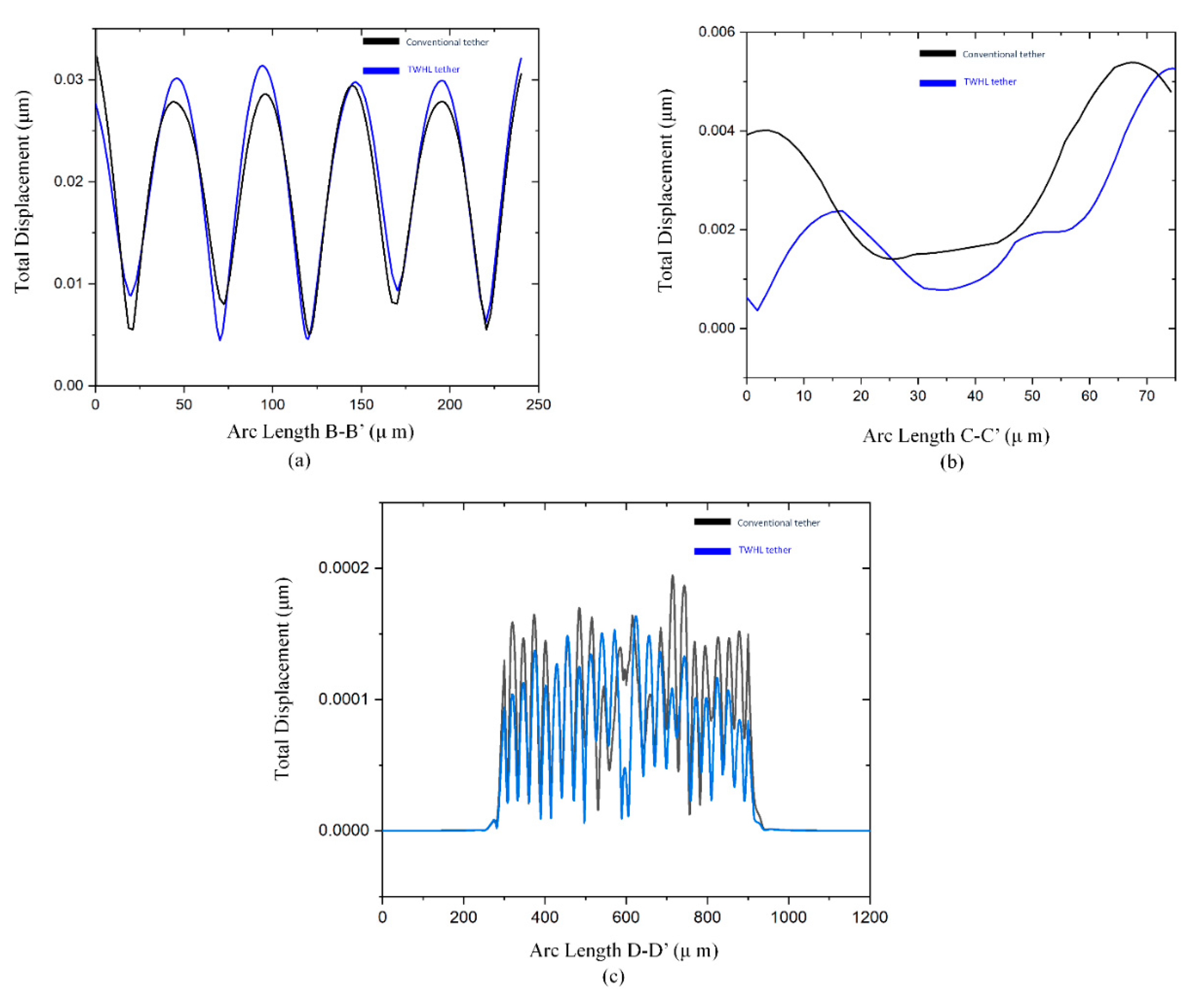
To prove the attenuation of the acoustic wave’s propagation through the supporting tethers, two designs of resonators were applied. The first resonator is a conventional tether, the second resonator is a TWHL resonator. The displacement profile of the resonant body at line B-B` in
Figure 8a, shows the resonator with TWHL has a total displacement of a resonant body equal to 0.32μm which is the highest displacement. This confirms that the energy stored in the TWHL resonator is higher than the conventional resonators. On the other hand,
Figure 8b,c at the lines C-C` and D-D` (see
Figure 4) verify that the resonator with TWHL has lower displacements at the tethers and anchoring boundaries, resulting in minimum energy leakage. This confirms the amount of energy stored in the resonant body of the resonator with TWHL is higher due to the prevention of energy escape to the anchors. As a result, a Q
anchor of value equal to 175,00 was achieved from the TWHL resonator compared to a Q
anchor of value equal to 58,000 from the conventional resonator resulting in 3-fold improvements.
Figure 9 illustrates the conventional and TWHL resonator vibration modes with different resonance frequencies 70.23MHz, 85.51MHz (desired design), and 106.5MHz. The three resonators operate in 5th order vibration mode, while the maximum anchor quality factor appears at resonator operate at 85.5MHz with conventional tether and with TWHL which achieves minimum energy loss.
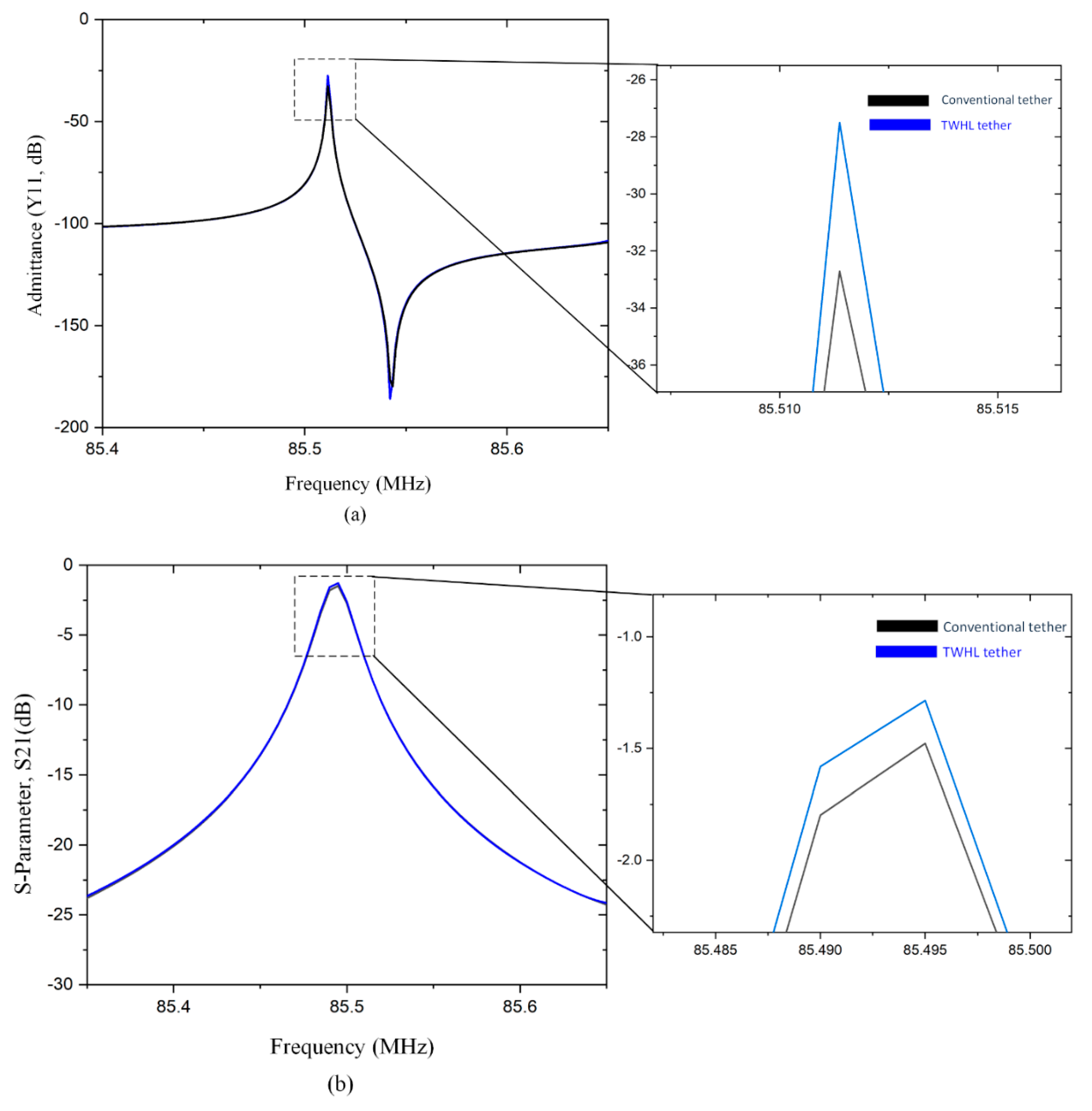
The resonator performance characteristics admittance Y
11 and S
21(dB) of the two resonators design (TWHL, conventional) are illustrated in
Figure 10a,b. The summaries of the results are, k
2eff of 0.08% is obtained from the TWHL resonator. Continuously, the simulated parameters such as insertion loss (IL) are 1.25 dB, the loaded quality factor (Q
l) is 3842, and the unloaded quality factor (Q
u) is 27,442 about 1.2-fold improvement as illustrated in
Table 2.
8. Conclusion
In this work, a new tether design was applied to a thin-film piezoelectric-on-Si micromachined resonator to enhance the anchor quality factor. The design and simulated results show significant enhancement in anchor quality factor from 58,000 to 175,000 representing 3-fold improvements compared to conventional tether design resonator. Continuously, the obtained Qu of the resonator with TWHL was 27,442 at 85 MHz, achieving a 1.2-fold enhancement in unloaded quality factor in comparison with a conventional resonator. The insertion loss was lowered from 1.5 dB to 1.25 dB for the proposed resonator design. The TWHL resonator performance parameters are significantly better than the conventional resonator.
Author Contributions
Conceptualization, M.A. and J.B.; Formal analysis, M.A.; Funding acquisition, M.A., J.B., and K.-y.H.; Investigation, M.A. and J.B.; Methodology, M.A. and J.B.; Project administration, T.B.W., J.B., and K.-y.H.; Resources, T.B.W., J.B., and K.-y.H.; Software, M.A.; Supervision. J.B. and K.-y.H.; Validation, J.B., and K.-y.H.; Visualization, M.A.; Writing—original draft, M.A.; Writing—review and editing, J.B. and K.-y.H. All authors have read and agreed to the published version of the manuscript.
Funding
This work is supported in part by the research project under grant A1098531023601318 and in part by the grant from the National Natural Science Foundation of China and the China Academy of Engineering Physics under grant U1430102.
Conflicts of Interest
The authors declare no conflict of interest.
References
- Zhao, C.; Montaseri, M.H.; Wood, G.S.; Pu, S.H.; Seshia, A.A.; Kraft, M. A review on coupled MEMS resonators for sensing applications utilizing mode localization. Sensors Actuators A: Phys. 2016, 249, 93–111. [Google Scholar] [CrossRef]
- Hou, Y.; Zhang, M.; Han, G.; Si, C.; Zhao, Y.; Ning, J. A review: aluminum nitride MEMS contour-mode resonator. J. Semicond. 2016, 37, 101001. [Google Scholar] [CrossRef]
- Pillai, G.; Li, S.-S. Piezoelectric MEMS Resonators: A Review. IEEE Sensors J. 2020, 21, 12589–12605. [Google Scholar] [CrossRef]
- Bhugra, H. and Piazza, G. eds., 2017. Piezoelectric MEMS resonators (p. 103). New York, NY, USA: Springer International Publishing.
- Chen, W.; Jia, W.; Xiao, Y.; Wu, G. Anchor Loss Reduction for Square-Extensional Mode MEMS Resonator Using Tethers With Auxiliary Structures. IEEE Sensors J. 2023, 23, 15454–15460. [Google Scholar] [CrossRef]
- Ha, T.D. Boosted anchor quality factor of a thin-film aluminum nitride-on-silicon length extensional mode MEMS resonator using phononic crystal strip. Appl. Phys. A 2021, 127, 1–9. [Google Scholar] [CrossRef]
- Li, J.; Chen, Z.; Liu, W.; Yang, J.; Zhu, Y.; Yang, F. A novel piezoelectric RF-MEMS resonator with enhanced quality factor. J. Micromechanics Microengineering 2022, 32, 035002. [Google Scholar] [CrossRef]
- Bao, F., Bao, J., Li, X., Zhou, X., Song, Y. and Zhang, X., 2019, April. Reflective strategy based on tether-integrated phononic crystals for 10 MHz MEMS resonator. In 2019 Joint Conference of the IEEE International Frequency Control Symposium and European Frequency and Time Forum (EFTF/IFC) (pp. 1-3). IEEE.
- Li, L.; He, W.; Tong, Z.; Liu, H.; Xie, M. Q-Factor Enhancement of Coupling Bragg and Local Resonance Band Gaps in Single-Phase Phononic Crystals for TPOS MEMS Resonator. Micromachines 2022, 13, 1217. [Google Scholar] [CrossRef]
- Siddiqi, M.W.U., Fedeli, P., Tu, C., Frangi, A. and Lee, J.E., 2019. Numerical analysis of anchor loss and thermoelastic damping in piezoelectric AlN-on-Si Lamb wave resonators. Journal of Micromechanics and Microengineering, 29(10), p.105013.
- Bao, F.-H.; Bao, J.-F.; Lee, J.E.-Y.; Bao, L.-L.; Khan, M.A.; Zhou, X.; Wu, Q.-D.; Zhang, T.; Zhang, X.-S. Quality factor improvement of piezoelectric MEMS resonator by the conjunction of frame structure and phononic crystals. Sensors Actuators A: Phys. 2019, 297, 111541. [Google Scholar] [CrossRef]
- Workie, T.B.; Wu, T.; Bao, J.-F.; Hashimoto, K.-Y. Design for high-quality factor of piezoelectric-on-silicon MEMS resonators using resonant plate shape and phononic crystals. Jpn. J. Appl. Phys. 2021, 60, SDDA03. [Google Scholar] [CrossRef]
- Zhu, H. and Lee, J.E.Y., 2015, January. AlN piezoelectric on silicon MEMS resonator with boosted Q using planar patterned phononic crystals on anchors. In 2015 28th IEEE International Conference on Micro Electro Mechanical Systems (MEMS) (pp. 797-800). IEEE.
- Ha, T.D. Anchor quality factor improvement of a piezoelectrically-excited MEMS resonator using window-like phononic crystal strip. Int. J. Mech. Mater. Des. 2023, 1–11. [Google Scholar] [CrossRef]
- Awad, M., Bao, F., Bao, J. and Zhang, X., 2018, May. Cross-shaped PnC for anchor loss reduction of thin-film ALN-on-silicon high frequency MEMS resonator. In 2018 IEEE MTT-S International Wireless Symposium (IWS) (pp. 1-3). IEEE.
- Li, J.; Chen, Z.; Liu, W.; Yang, J.; Zhu, Y.; Yang, F. A novel piezoelectric RF-MEMS resonator with enhanced quality factor. J. Micromechanics Microengineering 2022, 32, 035002. [Google Scholar] [CrossRef]
- Zhu, H.; Lee, J.E.-Y. Design of Phononic Crystal Tethers for Frequency-selective Quality Factor Enhancement in AlN Piezoelectric-on-silicon Resonators. Procedia Eng. 2015, 120, 516–519. [Google Scholar] [CrossRef]
- Rawat, U.; Nair, D.R.; DasGupta, A. Piezoelectric-on-Silicon Array Resonators With Asymmetric Phononic Crystal Tethering. 2017, 26, 773–781. [CrossRef]
- Tu, C.; Lee, J.-Y. Enhancing quality factor by etch holes in piezoelectric-on-silicon lateral mode resonators. Sensors Actuators A: Phys. 2017, 259, 144–151. [Google Scholar] [CrossRef]
- Gokhale, V.J.; Gorman, J.J. Approaching the intrinsic quality factor limit for micromechanical bulk acoustic resonators using phononic crystal tethers. Appl. Phys. Lett. 2017, 111, 013501. [Google Scholar] [CrossRef] [PubMed]
- Tu, C.; Lee, J.E.-Y.; Zhang, X.-S. Dissipation Analysis Methods and Q-Enhancement Strategies in Piezoelectric MEMS Laterally Vibrating Resonators: A Review. Sensors 2020, 20, 4978. [Google Scholar] [CrossRef]
- Harrington, B.P., 2013. Performance enhancement of micromachined thin-film piezoelectric-on-silicon lateral-extensional resonators through substrate and tether modifications. Oklahoma State University.
- Bao, F. H.; Awad, M.; Li, X. Y.; Wu, Z. H.; Bao, J. F.; Zhang, X. S.; Bao, L. L. Suspended frame structure with phononic crystals for anchor loss reduction of MEMS resonator. In 2018 IEEE International Frequency Control Symposium (IFCS), 2018. pp. 1-4. IEEE.
- Ha, T.D. A Two-Square Shaped Phononic Crystal Strip for Anchor Quality Factor Enhancement in a Length Extensional Mode TPoS Resonator. J. Vib. Eng. Technol. 2022, 10, 1073–1080. [Google Scholar] [CrossRef]
- Lv, S., Zhu, Z., Long, F., Sun, H., Song, C., Zhang, A., Tan, F. and Zhao, J., 2022. Characterization analysis of quality factor, electro-mechanical coupling and spurious modes for AlN Lamb-wave resonators with fs> 2 GHz. Microelectronics Journal, 125, p.105466.
- Das, B.M. and Sivakugan, N., 2018. Principles of foundation engineering. Cengage learning.
- Awad, M.; Workie, T.B.; Bao, J.-F.; Hashimoto, K.-Y. Reem-Shape Phononic Crystal for Q Anchor Enhancement of Thin-Film-Piezoelectric-on-Si MEMS Resonator. Micromachines 2023, 14, 1540. [Google Scholar] [CrossRef]
- Pillai, G.; Li, S.-S. Quality factor boosting of bulk acoustic wave resonators based on a two dimensional array of high-Q resonant tanks. Appl. Phys. Lett. 2020, 116, 163502. [Google Scholar] [CrossRef]
- Chen, W.; Jia, W.; Xiao, Y.; Wu, G. Design, Modeling and Characterization of High-Performance Bulk-Mode Piezoelectric MEMS Resonators. J. Microelectromechanical Syst. 2022, 31, 318–327. [Google Scholar] [CrossRef]
- Workie, T.B.; Wu, Z.; Tang, P.; Bao, J.; Hashimoto, K.-Y. Figure of Merit Enhancement of Laterally Vibrating RF-MEMS Resonators via Energy-Preserving Addendum Frame. Micromachines 2022, 13, 105. [Google Scholar] [CrossRef]
- Gokhale, V.J. and Gorman, J.J., 2017, January. Direct measurement of dissipation in phononic crystal and straight tethers for MEMS resonators. In 2017 IEEE 30th International Conference on Micro Electro Mechanical Systems (MEMS) (pp. 958-961). IEEE.
- Tong, Y.; Han, T. Anchor Loss Reduction of Lamb Wave Resonator by Pillar-Based Phononic Crystal. Micromachines 2021, 12, 62. [Google Scholar] [CrossRef] [PubMed]
- Siddiqi, M.W.U. and Lee, J.E.Y., 2018, January. AlN-on-Si MEMS resonator bounded by wide acoustic bandgap two-dimensional phononic crystal anchors. In 2018 IEEE Micro Electro Mechanical Systems (MEMS) (pp. 727-730). IEEE.
- Sun, H.; Wang, X.; Zhu, Z.; Zhao, J. Theoretical and experimental analysis of the spurious modes and quality factors for dual-mode AlN lamb-wave resonators. IEICE Trans. Electron. 2022, E106C, 76–83. [Google Scholar] [CrossRef]
- Ha, T.D.; Bao, J. A phononic crystal strip based on silicon for support tether applications in silicon-based MEMS resonators and effects of temperature and dopant on its band gap characteristics. AIP Adv. 2016, 6, 045211. [Google Scholar] [CrossRef]
- Liang, J.; Zhang, H.; Zhang, D.; Duan, X.; Zhang, H.; Pang, W. Design and fabrication of aluminum nitride Lamb wave resonators towards high figure of merit for intermediate frequency filter applications. J. Micromechanics Microengineering 2015, 25, 035016. [Google Scholar] [CrossRef]
- Thakar, V. and Rais-Zadeh, M., 2013, July. Optimization of tether geometry to achieve low anchor loss in Lamé-mode resonators. In 2013 Joint European Frequency and Time Forum & International Frequency Control Symposium (EFTF/IFC) (pp. 129-132). IEEE.
- Bijay, J.; Narayanan, K.N.B.; Sarkar, A.; DasGupta, A.; Nair, D.R. Optimization of Anchor Placement in TPoS MEMS Resonators: Modeling and Experimental Validation. J. Microelectromechanical Syst. 2022, 31, 571–579. [Google Scholar] [CrossRef]
- Qamar, A., Sherrit, S., Zheng, X.Q., Lee, J., Feng, P.X.L. and Rais-Zadeh, M., 2019. Study of energy loss mechanisms in AlN-based piezoelectric length extensional-mode resonators. Journal of Microelectromechanical Systems, 28(4), pp.619-627.
- Pillai, G.; Li, S.-S. Piezoelectric MEMS Resonators: A Review. IEEE Sensors J. 2020, 21, 12589–12605. [Google Scholar] [CrossRef]
- Workie, T.B.; Liu, J.; Wu, Z.; Tang, P.; Bao, J.-F.; Hashimoto, K.-Y. Swastika Hole shaped Phononic Crystal for Quality enhancement of Contour Mode Resonators. In 2021 IEEE MTT-S International Wireless Symposium (IWS) (pp. 1-3). IEEE.
|
Disclaimer/Publisher’s Note: The statements, opinions and data contained in all publications are solely those of the individual author(s) and contributor(s) and not of MDPI and/or the editor(s). MDPI and/or the editor(s) disclaim responsibility for any injury to people or property resulting from any ideas, methods, instructions or products referred to in the content. |
© 2023 by the authors. Licensee MDPI, Basel, Switzerland. This article is an open access article distributed under the terms and conditions of the Creative Commons Attribution (CC BY) license (http://creativecommons.org/licenses/by/4.0/).
