1. Introduction
According to the International Energy Agency, energy efficiency, behavioural change, electrification, renewables, hydrogen and hydrogen-based fuels, and CCUS are the key pillars to decarbonise the global energy system [
1]. The increasing share in cumulative emission reductions due to hydrogen justifies its important role in the Net zero Emissions Scenario [
1] to decarbonise sectors where emissions are hard-to-abate, such as heavy industry and long distance transport. Within the power sector, hydrogen holds the potential to deliver flexibility by aiding in the management of increasing proportions of fluctuating renewable energy generation. Additionally, it can play a role in enabling seasonal energy storage, further enhancing the versatility and reliability of the energy system.
Hydrogen stands out as an exceptionally versatile fuel that can be generated using a wide spectrum of energy sources, encompassing coal, oil, natural gas, biomass, renewables, and nuclear power. The production methods are equally diverse, spanning processes like reforming, gasification, electrolysis, pyrolysis, water splitting, and numerous others. In recent times, distinct colors have been assigned to signify different pathways of hydrogen production: "green" for hydrogen extracted through electrolysis with electricity from renewable sources; "grey" for produced from fossil raw materials such as natural gas (this generates around 10 tons of per ton of ); "blue" for production derived from fossil fuels with carbon capture, utilization, and storage (CCUS); "turquoise" for produced by splitting natural gas at high temperatures (only solid carbon is produced in the process, i.e., no is emitted if the process runs on heat from renewable energy sources). Due to the multitude of energy sources that can be employed, the environmental consequences associated with each method of hydrogen production can differ significantly. Moreover, the geographic location and the specific configuration of the process also play a crucial role in shaping these environmental impacts.
As of 2020, the worldwide demand for hydrogen amounted to approximately 90 million metric tons (Mt) [
1], indicating a growth of 50% since the year 2000. Nearly the entirety of this demand is attributed to applications in refining and industrial sectors. Refineries, on an annual basis, utilize nearly 40 million metric tons of hydrogen for tasks such as feedstock and reagents, as well as an energy source.
Demand is slightly elevated in the industrial sector, surpassing 50 million metric tons (Mt) of hydrogen [
1]. This demand is primarily attributed to its use as feedstock. Within the chemical production sector, approximately 45 million metric tons of hydrogen are consumed, with roughly three-quarters allocated to ammonia production and the remaining one-quarter directed towards methanol production. The remaining 5 million metric tons of hydrogen find usage in the direct reduced iron (DRI) process for steelmaking. This allocation of demand has remained nearly unchanged since 2000, with only a marginal uptick in demand noted for DRI production.
Simultaneously, mounting concerns about climate change have led to heightened awareness, prompting both governments and industries to make resolute pledges aimed at curtailing emissions. While this has expedited the integration of hydrogen into novel applications, the demand in this realm still remains quite limited. For instance, in the transport sector, the yearly hydrogen demand stands at less than 20 thousand metric tons (kt) of hydrogen, representing a mere 0.02% of the overall hydrogen demand. As illustrated in the IEA roadmap for achieving a net-zero state by 2050 [
2], the attainment of government decarbonization objectives will necessitate a significant and abrupt acceleration in the adoption of hydrogen technologies across various segments within the energy sector.
In the Net Zero Emissions Scenario [
2], the demand for hydrogen experiences a substantial increase, expanding nearly six times its current value to reach 530 million metric tons (Mt) of hydrogen by the year 2050. This surge in demand is divided, with half of it being allocated to the industry and transport sectors. In this scenario, the presence of hydrogen in the power sector undergoes a marked increase. Its utilization in gas-fired power plants and stationary fuel cells plays a crucial role in mitigating the challenges associated with the growing output from variable renewable sources, facilitating the integration of larger proportions of solar photovoltaic (PV) and wind energy, and furnishing seasonal energy storage solutions. Additionally, hydrogen’s application in buildings also encounters growth, although its adoption remains constrained to specific circumstances. In the same scenario projected for 2050, approximately one-third of the hydrogen demand is allocated to the production of hydrogen-based fuels. These fuels include ammonia, synthetic kerosene, and synthetic methane. Current applications of ammonia are primarily centered around nitrogen fertilizers, but now the interest is growing in other sectors, such as long-distance shipping of hydrogen and combustion, where co-firing of ammonia in coal-fired power plants has shown successful demonstrations; however, further research, development, and deployment efforts are necessary to advance the utilization of pure ammonia as a direct fuel source (also thermally and catalytically decomposed) in steam or gas turbines.
When hydrogen is burned, the primary resultant is water (), rendering it a genuinely emission-free fuel in terms of . The ultimate objective is to utilize 100% green hydrogen for combustion, supplanting natural gas entirely. In the interim, a more immediate goal involves blending hydrogen with natural gas to be used in gas turbines and other industrial combustion applications, thereby achieving a partial reduction in emissions. Nowadays, the term fuel-flexibility refers to combustion-based power generation systems (especially gas turbines) capability to operate with hydrogen blends as fuel in a stable, safe and reliable way when the content unpredictably varies in time due to intermittent production from renewables. Such blends range from hydrogen-enriched natural gas (HENG) to ammonia (a promising -carrier).
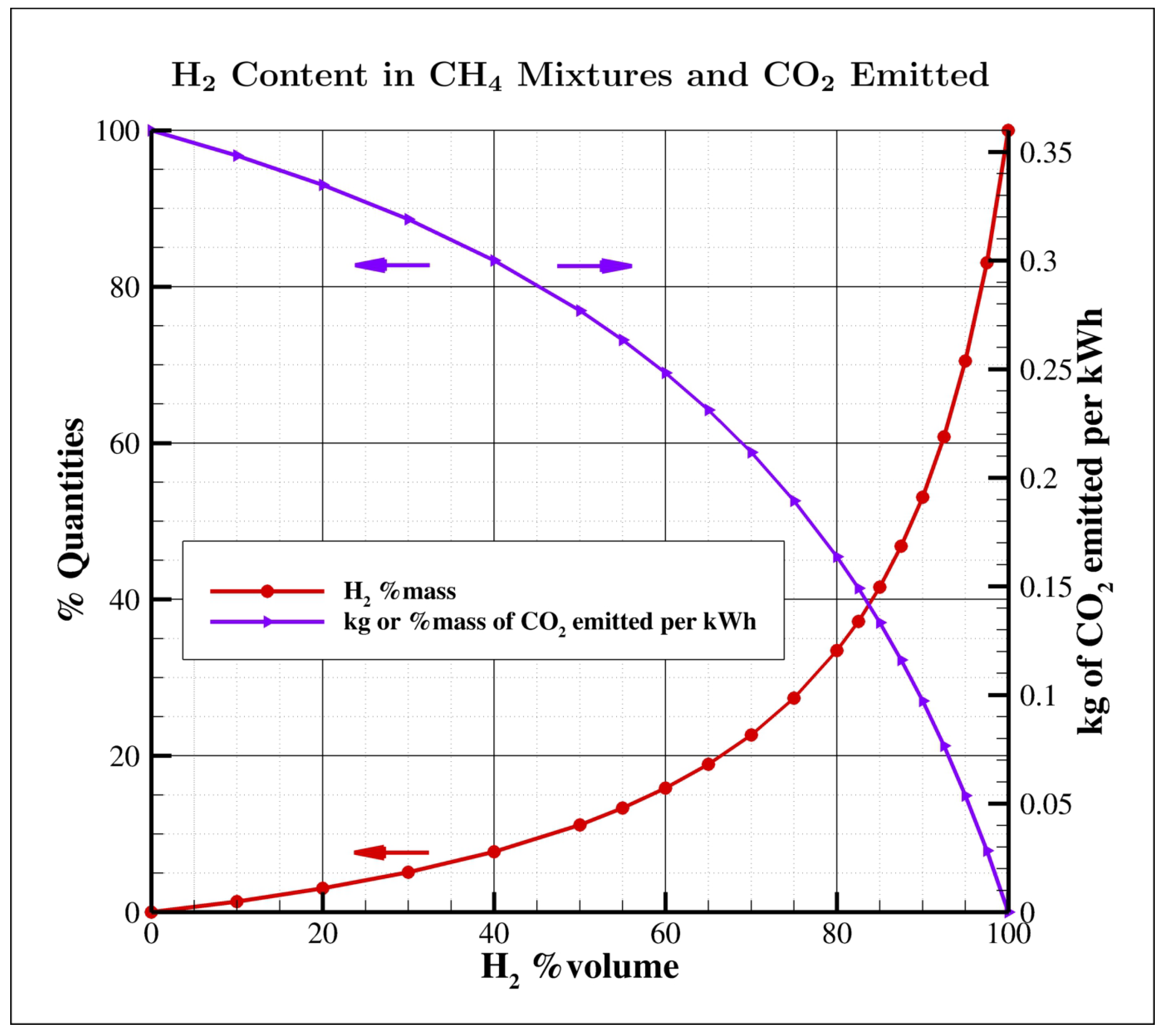
An important aspect, easy to understand but very often neglected is that large hydrogen mass fractions are required in fuel mixtures to significantly affect
emissions. Talking in terms of volume fractions is a common practice, but in a methane/hydrogen mixture the
volume percentage largely differs from its mass counterpart, as shown in
Figure 1; for example, 30 and 50% vol. correspond just to 5 and 11% mass, while 80% vol. is required to reduce
emissions by 55%. However, even the low 30% vol. becomes really challenging if significant temporal fluctuations of composition are considered.
Adopting hydrogen in combustion application is not straightforward. A fuel consisting in 100% hydrogen necessitates an extra volumetric flow of 208%, approximately three times more than that needed for methane to have the same power; hence, depending on the blend percentage, there might be a need to expand the size of piping and valves to manage the higher volumetric flow demanded by hydrogen. Its physical characteristics introduce complexities in terms of production, storage, and transportation, setting it apart from natural gas. Safety issues also arise due to hydrogen’s broader flammability range, lower vapor density, and faster flame speed, necessitating careful consideration within the framework of system design. Safety mechanisms for gas detection and fire protection must be adjusted to address hydrogen’s unique volatility and distinctive detection characteristics. Correspondingly, measures for explosion-proofing should be equipped to confine more substantial explosions, and modifications to ventilation systems are essential. Moreover, hydrogen encounters distinctive challenges related to supply and infrastructure. The fuel system’s pipelines and valves enclosed must harmonize with hydrogen, necessitating materials that are hydrogen-compatible and designed with safety factors in mind. Additionally, the design must incorporate hydrogen-tight seals capable of accommodating the small hydrogen gas molecules.
In this article, combustion features of hydrogen enrichment in fuel blends will be firstly considered, also briefly looking at effects on materials. Then, an overview of combustion applications in power generation and hard-to-abate sectors will be provided to identify the state-of-the-art and the barriers for its exploitation. In the end, conclusions and future directions will be drawn.
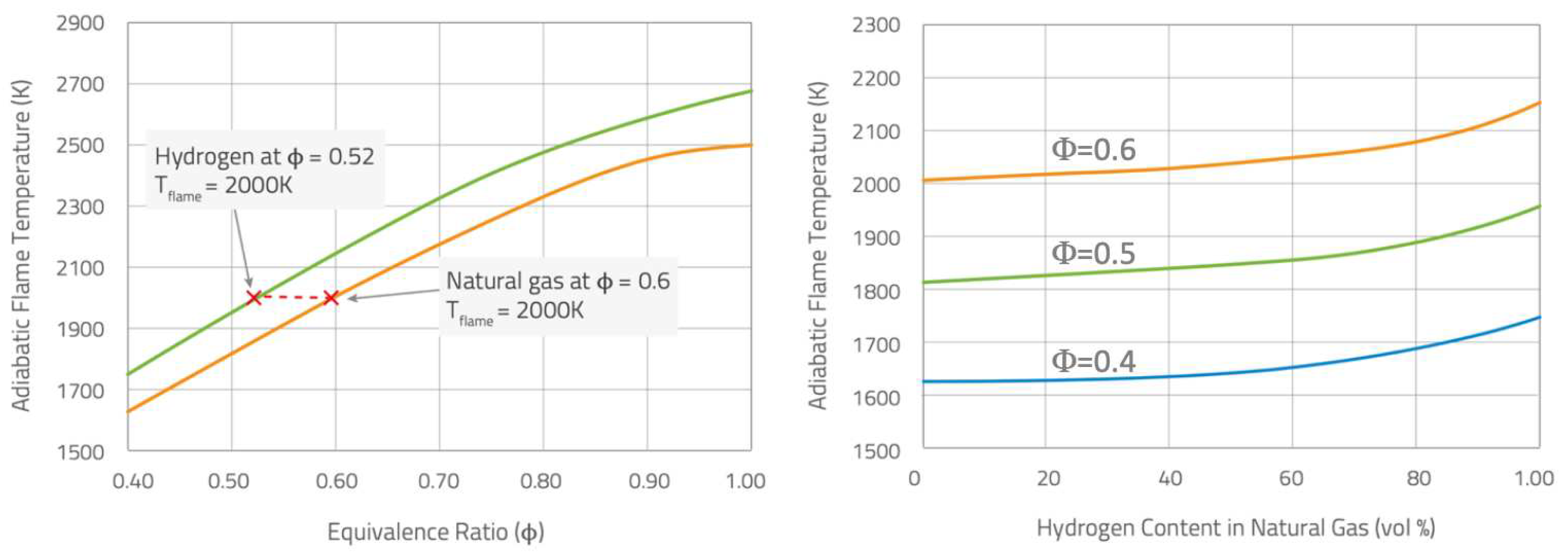
Figure 2.
Adiabatic flame temperature
vs equivalence ratio (
) for hydrogen and methane flames in air (left), and
vs hydrogen content for some specific mixtures (right) [
3].
Figure 2.
Adiabatic flame temperature
vs equivalence ratio (
) for hydrogen and methane flames in air (left), and
vs hydrogen content for some specific mixtures (right) [
3].
2. Features of Hydrogen Combustion
When employing hydrogen either alongside natural gas or as a complete substitute, it’s crucial to grasp the distinctions between these two fuels.
Hydrogen possesses a density that is one-ninth that of natural gas, and it holds the distinction of being the smallest known molecule. This characteristic introduces challenges regarding transportation and sealing. Furthermore, hydrogen’s heating value is merely one-third that of natural gas (on volumetric basis), signifying that three times the amount of hydrogen fuel is necessary to generate an equivalent power output compared to natural gas. In the combustion of hydrogen, while more volume flow is required for the same energy production, approximately 20% less air by volume is required to produce a flame comparable to natural gas, thus reducing the mass flow through the combustor and consequently the convective heat transfer. Under this perspective, flue gas recirculation can be used to increase the mass flow of air into the combustor, increasing convective heat transfer and reducing the flame temperature [
4,
5,
6].
Moreover, hydrogen has a considerably broader flammability range than natural gas, leading to heightened concerns regarding environmental, health, and safety aspects during both hydrogen transportation and combustion Hydrogen largely enhances the reactivity of fuel blends: the ignition delay time decreases [
7,
8]; at room temperature and pressure the flammability limits (0.1-7.1) are well wider than those of natural gas (0.5-1.67); the flame speed is higher [
9] and the critical strain rate increases, thus reducing potential flame quenching [
10,
11]. At fixed equivalence ratio (
), the hydrogen/air premixed flame burns with an adiabatic flame temperature higher than the corresponding natural gas one (see
Figure 2, left). In the same way, fixing the equivalence ratio, the increase of the hydrogen content in a methane/hydrogen mixture can rise the adiabatic flame temperature (see
Figure 2, right).
The higher hydrogen combustion temperatures produce an increase of nitrogen oxides,
, most of which is thermal, i.e., coming from high temperature regions with sufficiently long residence time [
12]. This is one of the main concerns in operating burners with fuel blends having high
content.
2.1. Effects on Flame Stability
Combustion in excess of air can mitigate
production [
13], but at these conditions of extremely lean combustion, the gaseous mixtures rich in hydrogen are characterized by a disparity between the diffusion by mass and the thermal one, inducing phenomena of intrinsic instability with a strong impact on the laminar and turbulent combustion speed, thus altering the flame topology.
These effects have been predicted theoretically [
14,
15,
16], and also visualized experimentally [
17,
18] and numerically (numerical simulations) [
19,
20,
21]. In particular, these reactive mixtures are extremely sensitive to some external perturbations (usually present in every burner) producing exponential growths in the extension of the flame front, in pressure fluctuations, as well as in temperature, with a negative impact on the performance of thermal machines, their polluting emissions and even their life time. However, with an accurate design of the combustion chamber, it is possible to maximize the advantages deriving from these instabilities, i.e., the increase in the average combustion speed (and therefore in the thermal power) and compactness of flames (smaller size of the devices), while eliminating or mitigating the negative aspects, such as high pressure and temperature fluctuations, localized quenching and flashbacks.
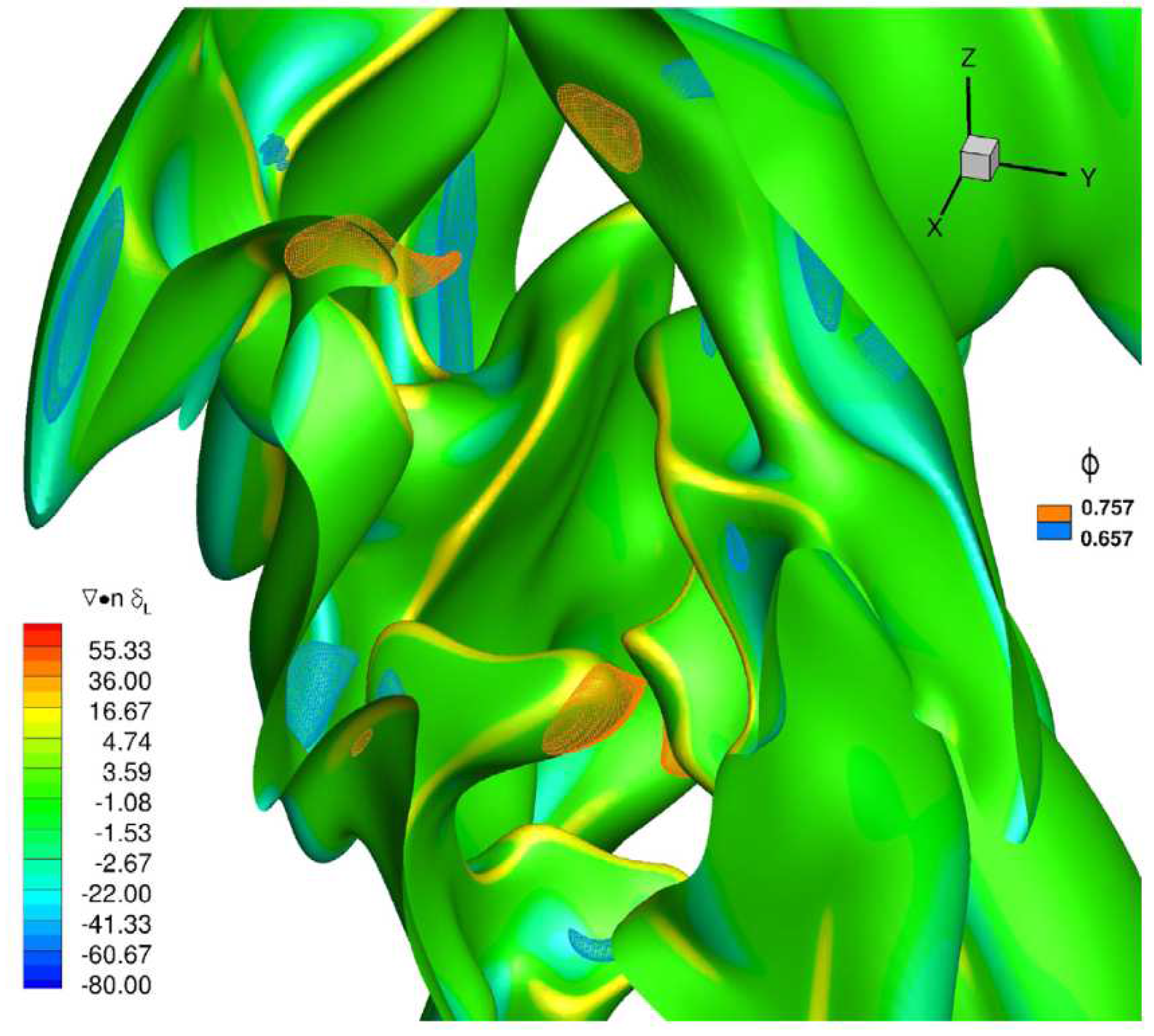
Hydrogen, and light species in general, diffuse preferentially with respect to other species in a mixture. In recent decades, so-called asymptotic theories have been developed which predict the existence of perturbations (in specific wavelength ranges) particularly effective in destabilizing combustion processes, which strongly depend on the Lewis number of the mixture. The Lewis number (Le) represents a measure of the disparity between thermal and mass diffusivity, through their ratio: therefore a hydrogen-rich mixture, which has a mass diffusivity extremely greater than the methane molecule, will be characterized by a Lewis number less than unity. In premixed combustion, this makes local equivalence ratio lower or higher than the inlet nominal equivalence ratio of the considered fuel blend depending on the local flame curvature. An example is provided in
Figure 3 for a
flame at a nominal
and 20%
volume content [
22], where the instantaneous flame surface (identified by means of the progress variable value related to the maximum heat release) is shown evidencing local hydrogen enrichment in positive curvature regions, and a decrease of equivalence ratio in negative curvature regions. This mechanism changes flame speed locally, and tends to enhance the wrinkling of the flame front and the burning rate.
Mixtures with Lewis numbers smaller than a critical value (
, generally less than one) will be characterized by small-scale (thermo-diffusive) and large-scale (hydro-dynamic) instabilities. With a Lewis number close to the
or greater, mainly hydro-dynamic instabilities will survive. This type of instability is based on different formation mechanisms. In the case of thermo-diffusive instabilities, the high diffusivity of the mixture (in particular of
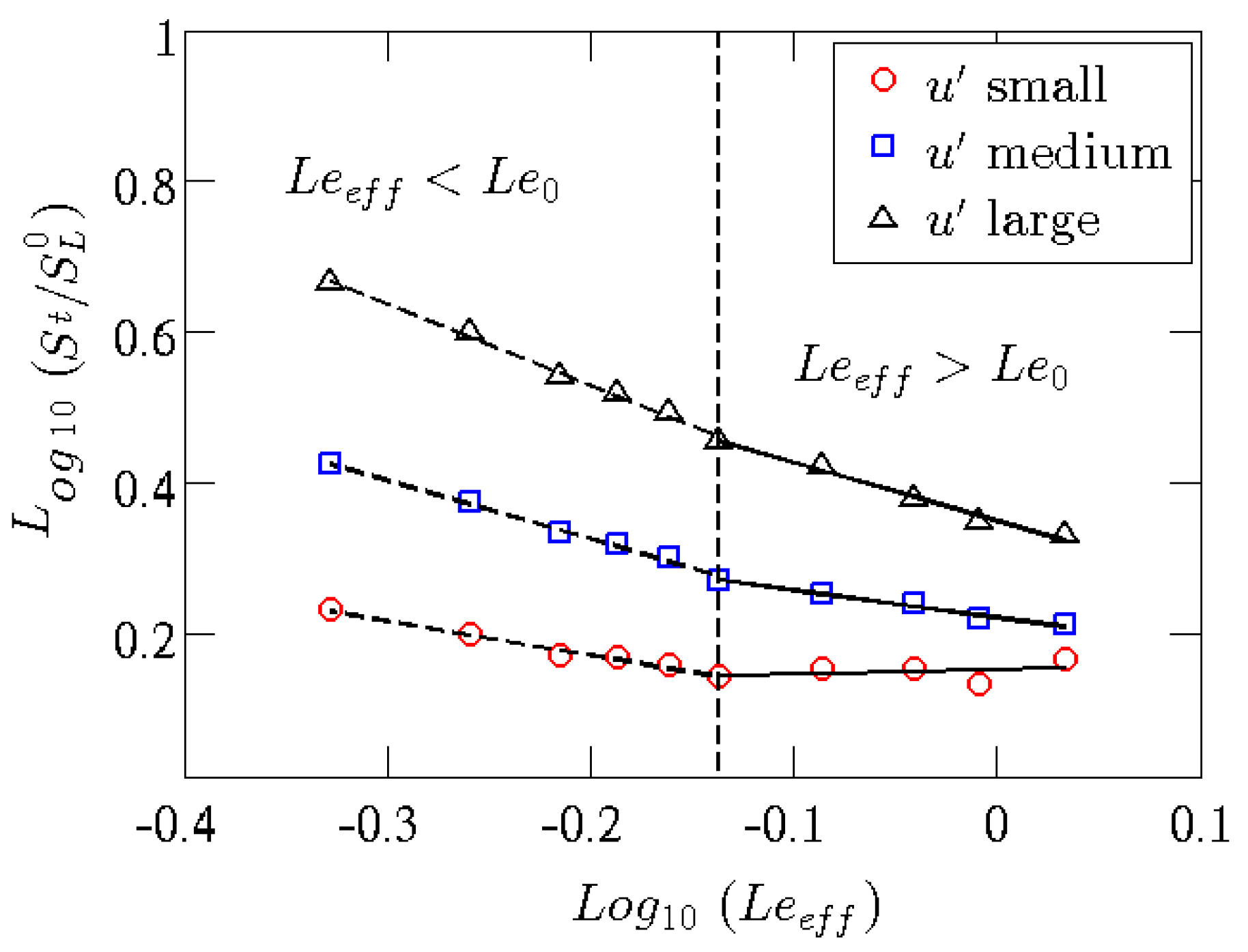
) will give rise, when the flame front is perturbed/corrugated, to inhomogeneity of the equivalence ratio of the mixture and of the local temperatures with a consequent variation of the local laminar combustion speeds, which in turn will amplify the initial perturbations of the front, making it even more corrugated. Such corrugations increase the turbulent flame speed, as shown in
Figure 4 that reports the ratio between the turbulent and laminar flame speeds of a premixed
Bunsen flame: the lower the Lewis number and the higher the turbulence intensity, the higher the turbulent flame speed will be [
23].
This phenomenon is more effective the more the perturbations, and the corrugations of the front are of small scale. In the case of this phenomenon is strongly limited, and what arises is a hydro-dynamic type mechanism, in which the large-scale corrugations of the front compress or expand the stream lines of the flow field, thus channeling areas with low or high velocity upstream of the flame front. Also this mechanism tends to amplify initially small amplitude perturbations.
The presence of thermo-diffusive instabilities alone is not possible. In fact, being the hydro-dynamic instability a phenomenon always present in a flame, due to the difference in temperature between reactants and combustion products, that of the thermo-diffusive type is driven by the disparity between mass and thermal diffusivity, which can be eliminated by acting on the composition of the reactant mixture. Studies present in literature have shown the interaction, in Bunsen geometries, of hydrodynamic instabilities with flow turbulence [
25,
26,
27,
28,
29], while the characterization of the interaction of turbulence with both instabilities (hydro-dynamic and thermo-diffusive) still lacks.
Given its higher combustion temperature and faster flame speed, hydrogen combustion can lead to instability and an increased risk of flameouts and flashback events. In particular, the high reactivity of hydrogen inherently increases the risk of self-ignition and flashbacks in the premix section. The problem becomes even more important in systems with very high inlet air temperatures [
30,
31], as in highly recuperated gas turbines. Furthermore, compared to natural gas flames, hydrogen flames exhibit significantly different thermoacoustic behavior due to higher flame velocity, shorter ignition delay, and distinct flame stabilization mechanisms, resulting in different flame shapes, different positions and different reactivity. Therefore, the risk of combustion dynamics (self-sustained oscillations at the acoustic frequency of the combustion chamber) in gas turbines running on hydrogen enriched fuels is higher than in natural gas operation [
32,
33]. This implies that undesirable and dangerous phenomena such as combustion instability, flashbacks and lean-blowouts, can occur not only at steady state, but also during transient regimes, for example when the power changes rapidly and/or the fuel composition varies.
2.2. Effects on Pollutant Emissions
The main emission indicators on which the performance of burners are based are mainly nitrogen oxides , composed of and , and carbon dioxide .
There is no fundamental chemical kinetic reason why
flames should produce more
than natural gas flames. Since most of
is thermal, i.e., produced where reactants are at high temperature for a sufficiently long residence time (above a certain threshold temperature, around 1800 K, the production of
increases dramatically), more lean mixtures have to be adopted to reduce peak temperatures (see
Figure 2) when burning fuel blends with higher
content.
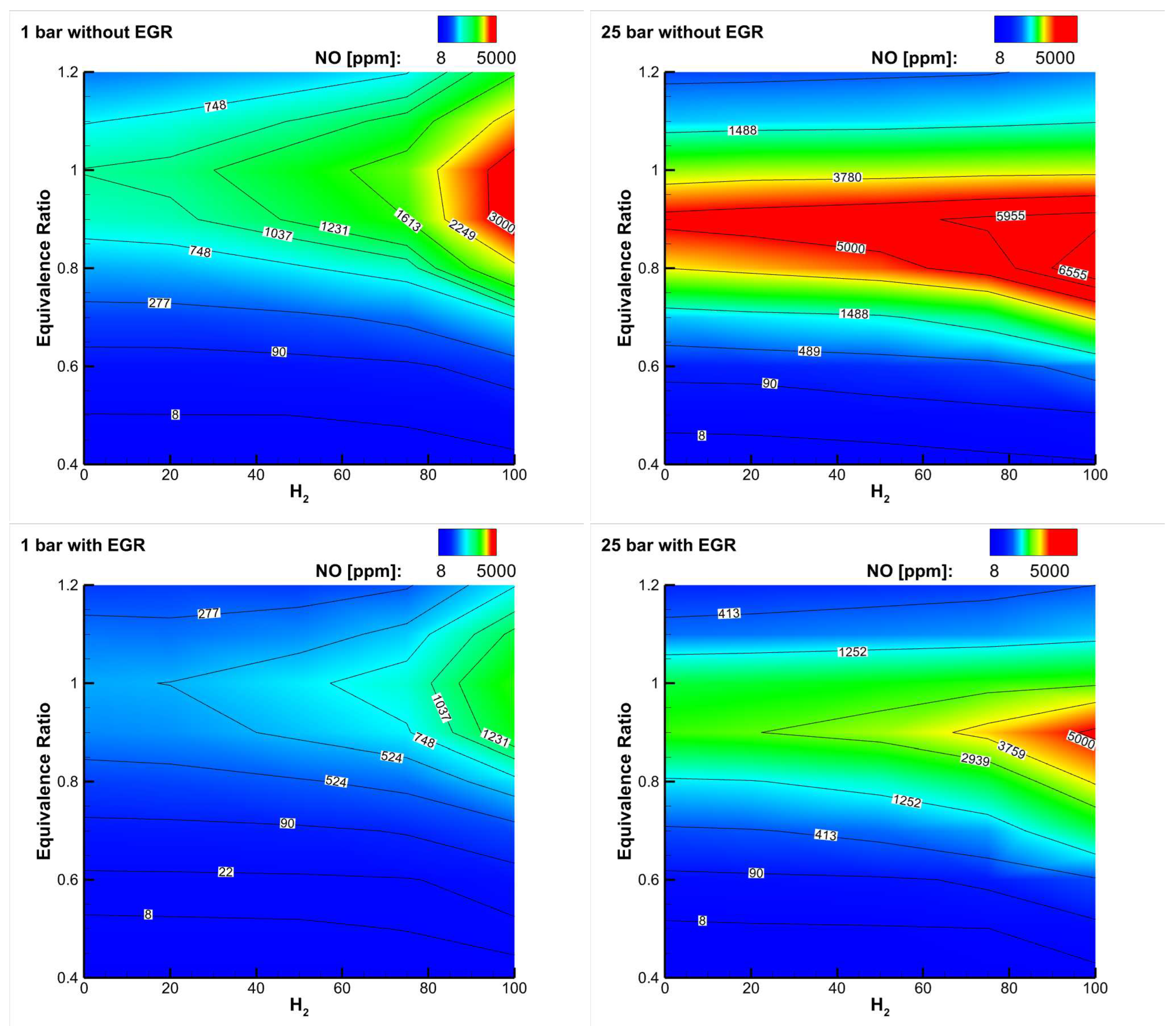
Figure 5 (top) shows a map of
emissions as a function of the equivalence ratio and hydrogen content for a
blend reacting with air at two different pressures [
34]: respecting
emission limits requires to operate at an equivalence ratio well below 0.5, especially at high
content and high pressure. Implementation of exhaust gas recirculation (EGR) can be of help in reducing
emissions in different applications (see
Figure 5, bottom), and in gas turbines it is a potential solution to enhance their turn-down ratio, i.e., to reduce their partial load (minimum technical environmental load).
Apart from
predictions and expectations from chemical kinetics calculations, some direct measurements of
emissions in a specific premixed Bunsen burner at 1 atmosphere are here reported due to the interesting operational strategy implemented to avoid flashback occurrence [
35]: as the hydrogen content increases in the
fuel blend, driving to the increase of flame propagation speed, the value of the equivalence ratio is decreased by increasing the excess air. This strategy allowed to maintain the flame propagation speed constant (
) and at the same time lowered the adiabatic flame temperature; besides, the power was kept constant (
) by raising the flow rate of the reactant mixture. Such a strategy avoided flashback up to the maximum jet Reynolds number (explored range, 10.000-13.900) in [
35]: it would be interesting to see what happens at higher turbulent jet Reynolds numbers to check the effects on the non-linear increase of the turbulent flame speed. The measurements of emissions were carried out at the chimney, taking a small quantity of combustion products and analyzing them by means of the FTIR (Fourier transform infrared spectroscopy) technique. [
36,
37].
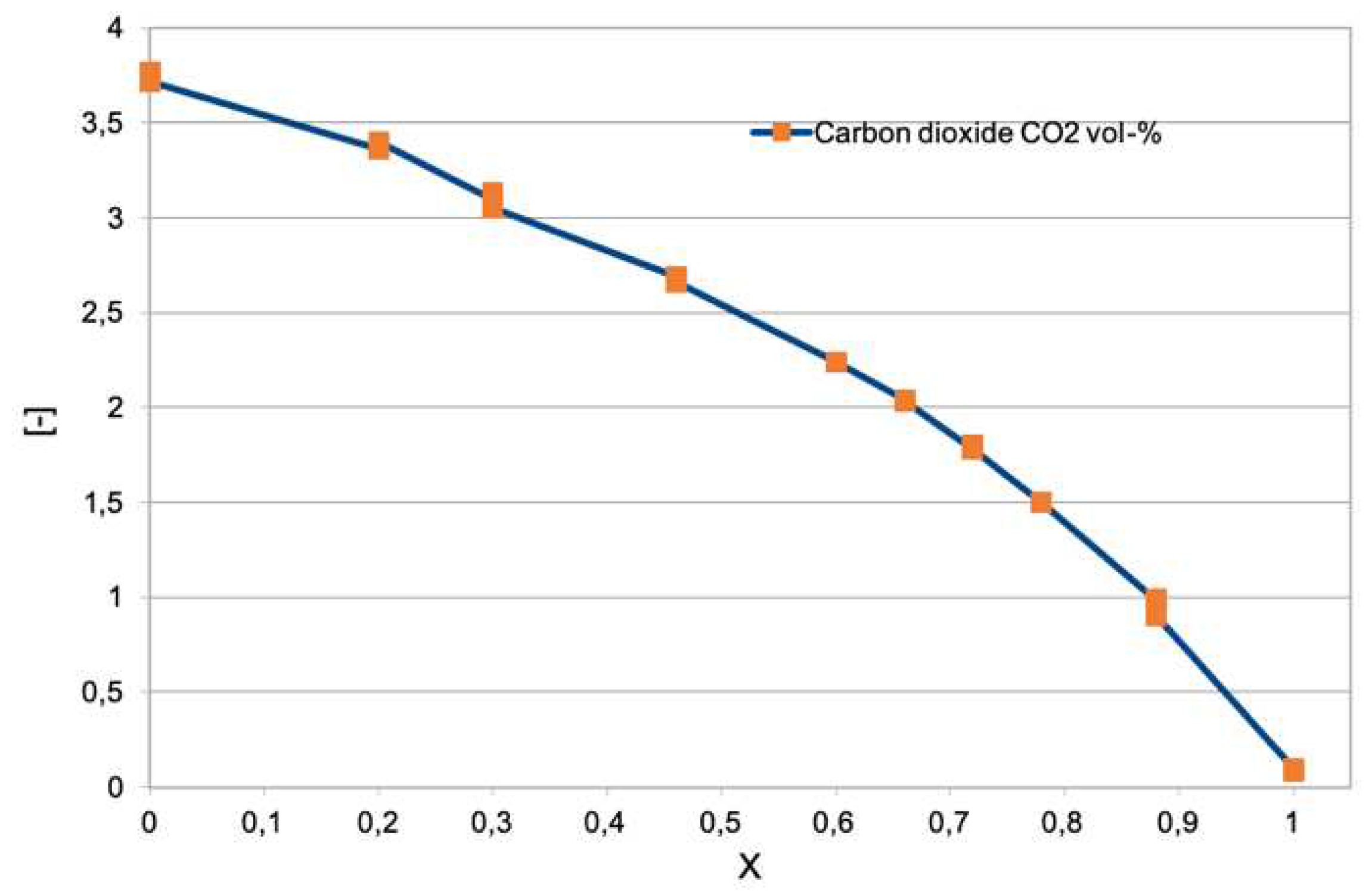
Figure 6 shows the results of the sampling of the carbon dioxide emitted [
35]. As the percentage of hydrogen, expressed as molar fraction, increases (0, pure methane; 1, pure hydrogen), the carbon dioxide content drops until it reaches zero when the mixture is made up of only hydrogen and air. Results are in agreement with the chemiluminescence emission described later in
Figure 10 and
Figure 11. As expected from data in
Figure 1, the presence of carbon dioxide is significant even at very high
mole fraction values.
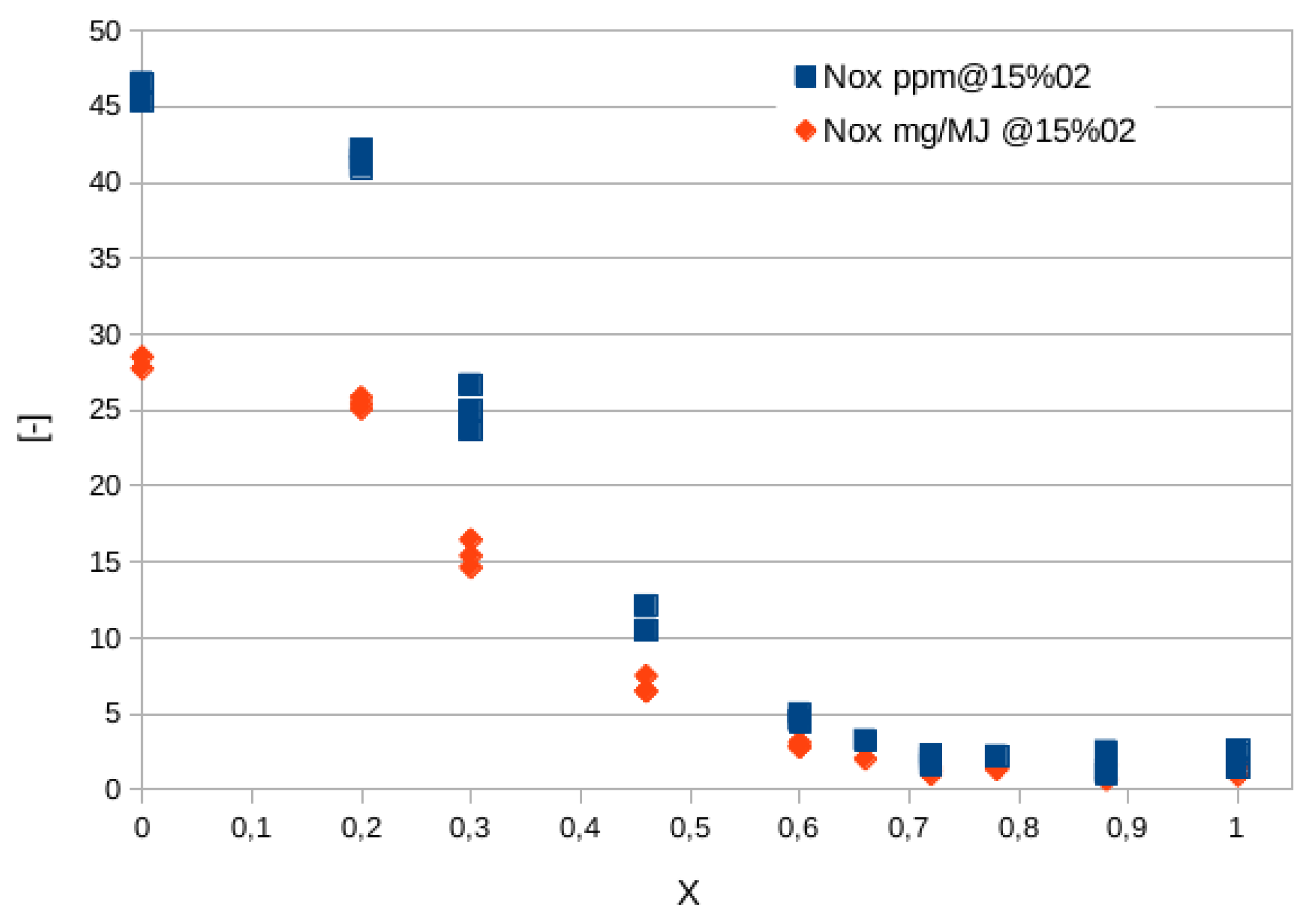
Figure 7 shows the quantity of
expressed in parts per million (ppm), scaled to a value of oxygen in the combustion equal to 15%, and also in mass normalized by the the fuel energy actually converted into heat, to take into account the different composition of exhausts while increasing the hydrogen content [
35]. Besides, in this way the emission values of machines of significantly different sizes (power) can be compared. It is observed that above a hydrogen mole fraction of 45-50%, emissions decrease dramatically. This is due to the regulation strategy adopted in [
35]: while hydrogen content is increased, the equivalence ratio is decreased thus lowering the flame temperature and thermal
contribution (the most relevant). In fact, temperature changes from about 2100 K for the methane flame to nearly 1600 K for the hydrogen one.
2.3. Effects on Radiant Energy Transfer
The Radiative Trasfer of Energy (RTE) is a very important mechanism in several applications: high-pressure and high-temperature engine combustion chambers, rocket propulsion, hypersonic vehicles, spacecraft atmospheric reentry, ablating thermal protection systems, glass manufacturing, plasma generators, nuclear fusion.
Notably, hydrogen flames are significantly less visible than those produced by natural gas, due to the reduced concentration of radiant species such as soot,
and radicals. This makes flame detection a more intricate endeavour; infrared flame detection is ineffective for a hydrogen flame, which means an ultraviolet system is required [
38,
39,
40,
41]. At the same time, this affects also the radiative heat transfer from the flame, with important implications in some applications, such as glass furnaces. The lower emissivity and lower mass flow rate (less air is required while increasing
content) of the combustor therefore change the heat transfer balance.
Radiative absorption properties depend on the absorption coefficient
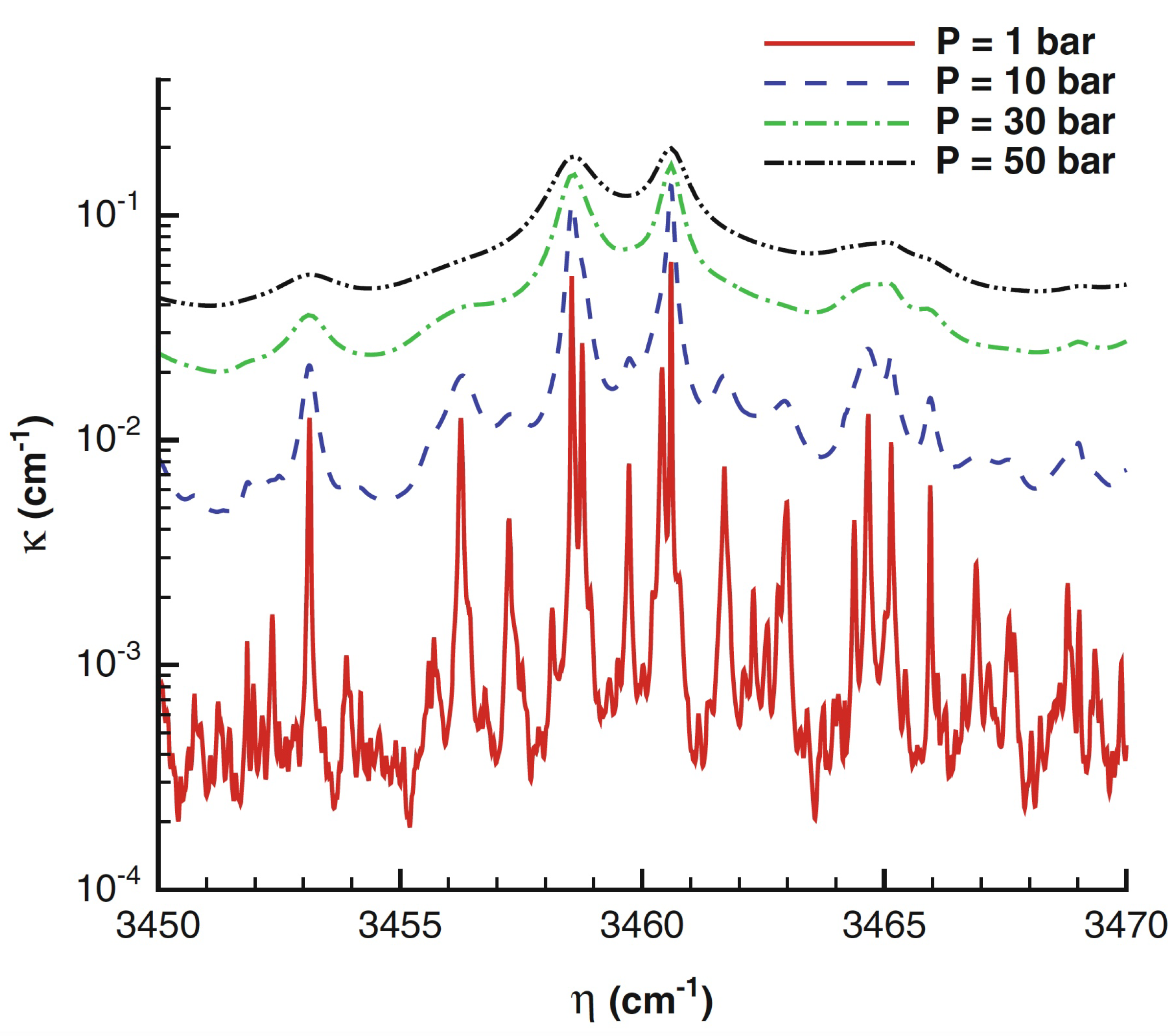
that in gases often varies strongly with wavelength, temperature and pressure. It also increases proportionally to the concentration of the participating species. While solid surfaces can be assumed opaque, gas absorption or emission properties are very irregular in the wavelength domain, being significant only in certain wavelength regions, especially at temperature below a few thousand Kelvin. When the temperature increases, the absorption coefficient of cold lines decreases but hot lines appear at high wavelengths, slightly increasing the absorption coefficient. Increasing pressure causes spectral line broadening, that is mainly due to molecular collisions [
42] and can produce wider and more overlapping lines than at lower pressures: as a consequence, the gas becomes ”grayer” (opaque) and the spectral absorption coefficient amplitude largely increases, as shown in
Figure 8 [43, p. 138] or reported in [
44]. An appropriate and convenient mean absorption coefficient to account for the total emission from a volume element of absorbing medium is the Planck mean absorption coefficient, that depends only on the local properties and can be tabulated. Today, the Planck mean absorption coefficient estimated in the past [42, p. 253-324], can be more accurately calculated [
45] directly from high-resolution spectroscopic databases, such as HITRAN [
46] and HITEMP [
47]: the new databases produce absorption coefficients generally larger than those obtained through older databases, especially at higher temperatures and pressures.
At industrial furnace and combustion chamber temperatures the gaseous species that absorb and emit significantly are , , , , , and . Other gases, such as , and , are transparent to infrared radiation and do not emit significantly; however, they become important absorbing/emitting contributors at very high temperatures. A non-negligible contribution to radiation is also provided by hot carbon (soot) particles within the flame and from suspended particulate material (as in pulverized-coal combustion).
Concerning flames, it is well known that neglecting radiation at atmospheric pressure conditions may lead to overprediction of temperature of up to
. However, it has to be noted that numerical predictions strongly depend on the RTE model adopted: the usually-employed optically-thin or gray radiation models lead to underprediction of temperature of up to
and more [
48,
49]. Furthermore, radiation is enhanced by turbulence through strong nonlinear interactions between temperature and radiative property fluctuations (TRI): such interactions increase the heat loss from a flame leading to a reduction in the local gas temperature of
and more. The TRI cooling effect is even enhanced in high-pressure combustors that typically exhibit larger optical thicknesses [
50,
51].
For systems where RTE is important, radiation was shown to be equivalent to a large nonlinear diffussion term: in fact, the radiant transfer of heat can work as a preheating mechanism as conduction of heat, thus resulting in higher flame speeds [
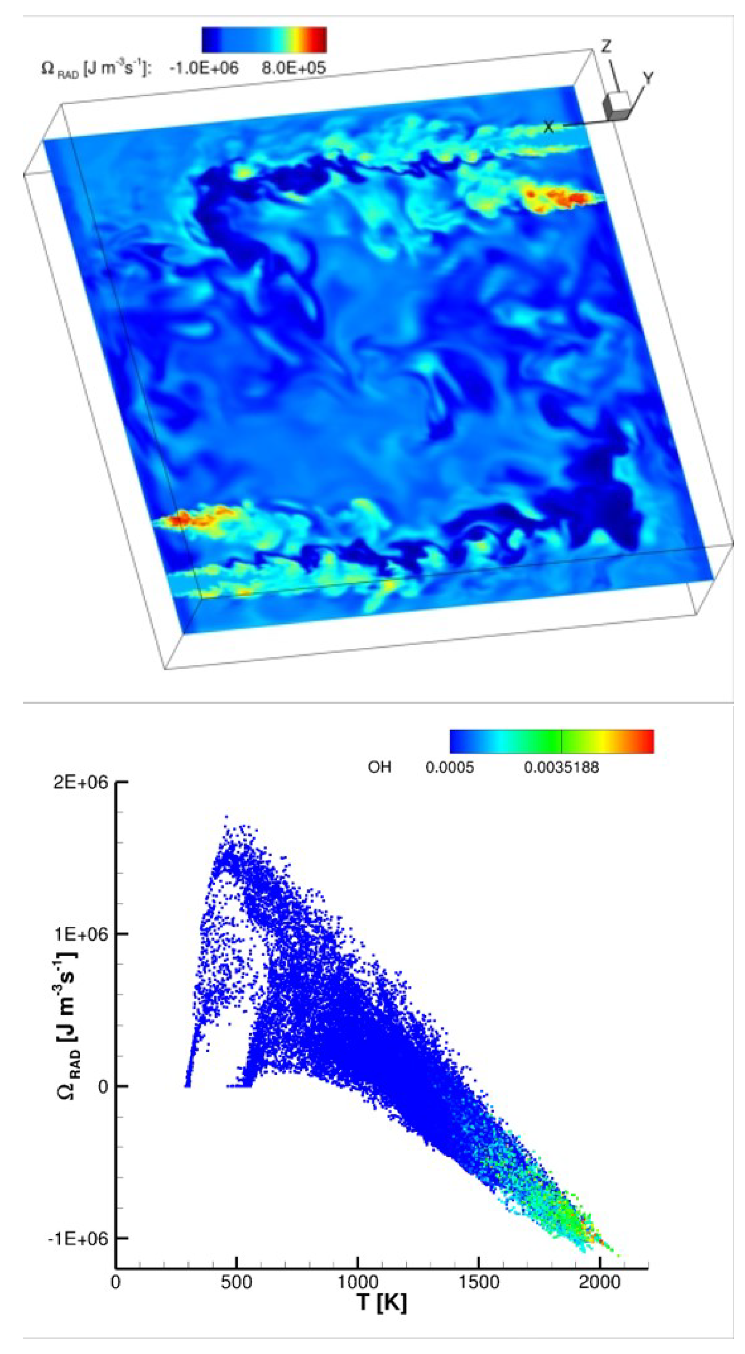
52]. As an example,
Figure 9 shows an instantaneous distribution of the radiative source term in the energy equation in a non-premixed cyclonic combustor [
53] burning air and hydrogen in MILD combustion regime. The source term is estimated by means of the M1-radiation model [
54]: its distribution reveals regions exhibiting heat losses (negative radiative source term) or preheating effects (positive source). The distribution of the radiative source term versus temperature is also shown at the bottom of the same figure, coloured by means of the OH radical mass fraction: higher temperature reacting regions with higher OH concentrations loose heat, while colder non-reacting regions (jets, identifiable in the planar section of
Figure 9, top) with lower OH content are preheated.
Focusing on peak flame temperature, radiation typically reduces it in low pressure flames. Although radiation effects become more pronounced as the pressure is increased (due to increased emission/absorption), the peak flame temperature is less affected by radiation because of the faster chemical reactions, as also observed in [43, p. 139]. In fact, according to the Arrhenius law, the chemical reaction rate is proportional to reactant molar concentrations raised to a power that is equal to the number of moles that have to collide for the reaction to occur. Hence, the reaction rate is proportional to
p for first-order reactions and to
for second-order reactions; three-body reactions, are even more enhanced [
55].
It is known that hydrogen flames have lower emissivity than natural gas flames. Such radiative emission changes may have important implications in some applications [
56].
In [
35] a series of premixed Bunsen flames at constant 7.1 kW thermal power, burning methane and hydrogen in air at atmospheric pressure with increasing hydrogen content, were experimentally investigated. While increasing the hydrogen content, the thermal power was kept constant maintaining the same laminar flame speed of the fuel mixture (hence, decreasing its equivalence ratio) and increasing the flow rate (hence, the jet Reynolds number). The spectrum of the electromagnetic radiation emitted was measured in a range of wavelengths between 200 and 1080 nm (nanometer), from ultraviolet to near infrared. The radiation emitted was collected by a system of lenses capable of focusing the image of the flame in an area of about 1-2 cm, where it was collected by an integrating sphere and sent, through an optical fibre, to a digital spectrometer. The integrating sphere is a spherical device which has the ability to concentrate almost all of the radiation collected inside it through a hole of about 1 cm made on its surface: measurement details can be found in [
35,
57]. The result is that, by integrating the measurement over a rather large surface of flame, the spatial dependence of the measurement is substantially lost, highlighting the spectral dependence on the wavelengths and the type of mixture.
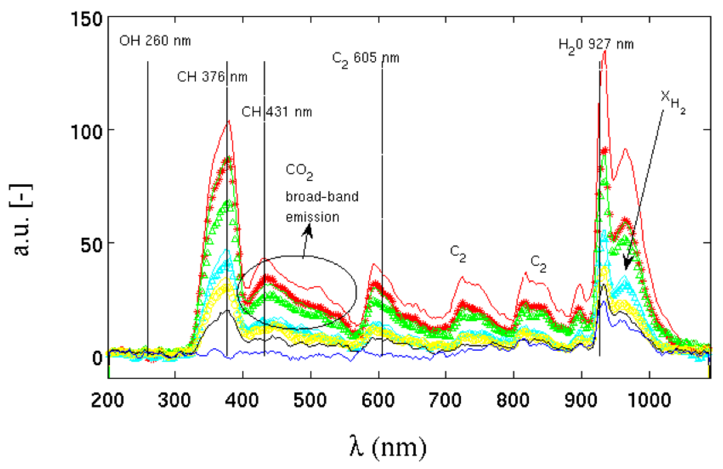
Figure 10 shows the spectra of radiant energy emitted by flames in [
35] with increasing hydrogen contents. The arrow with
defines the direction in which the molar fraction of hydrogen in the methane/air mixture increases. It starts from a pure methane flame, up to a pure hydrogen flame. The figure also shows the spectral emission lines of the major emitting species. As the carbon content in the mixture decreases, the decrease in energy emitted by the species
,
,
,
and
is evident.
Figure 10.
Emission spectrum at different hydrogen contents. The arrow points to the increasing direction of the hydrogen molar fraction.
Figure 10.
Emission spectrum at different hydrogen contents. The arrow points to the increasing direction of the hydrogen molar fraction.
As the hydrogen content in the mixture increases, the contribution of carbon to the emission of radiative energy progressively decreases until, in the mixture of pure hydrogen, only the emission peak of water and
survives, strongly reducing the ratio between radiant/convective energy emitted. In all the mixtures, the emission peak of the OH radical, located in the ultraviolet around a wavelength between about 260 and 310 nm, is substantially absent, despite being a chemical species strongly present inside the flame front. According to the authors in [
35], the reason for this absence could lie in the low sensitivity of the instrument at those wavelengths such as to return a signal-to-noise ratio that is too low for this type of measurement. Even with this lack, the differences in radiant energy emitted with the presence or absence of methane are considerable.
A lower radiative emission translates into a greater quantity of energy which is transmitted by convection, which mainly follows an axial direction, whereas the radiative one is emitted in all directions, and, given the cylindrical symmetry of the flame, preferentially in a radial direction. While this is beneficial for gas turbine applications (lower heat losses to walls and less cooling issues), it could be a serious issue in other industrial applications like raw-material melting kilns or product cooking kilns.
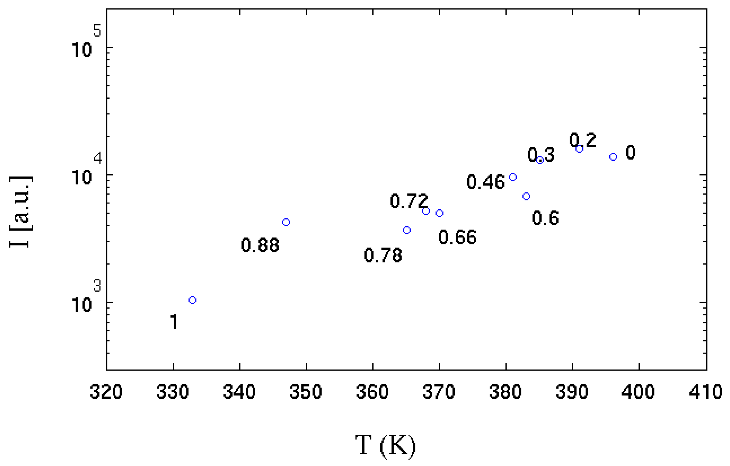
In the same experiments [
35], the temperature of a strongly absorbing metal body (black coloured) positioned on the flame side at a distance of about 2 diameters D (D, the diameter of the Bunsen burner adopted) was measured by a thermocouple. The correlation between the radiant energy emitted in radial direction and temperature is shown in
Figure 11. It can be seen that as the hydrogen content increases, the value of the integral of the radiative emission (I) is linearly anti-correlated with the temperature reached by the absorbent body. It can be deduced that the reduction of the chemical species that emit by chemiluminescence strongly influences the amount of radiative thermal energy emitted. It is also observed that up to a hydrogen volume content of 78% (30% by mass of hydrogen) this phenomenon is strongly limited: even a minimal quantity (in volume) of methane is sufficient to "colour" the flame, which emits over a more extensive range of wavelengths; the flame is instead almost colourless when the carbon is absent.
Figure 11.
Integrated emission spectrum (over all wavelengths) for the various hydrogen contents
vs temperature measured in the radial direction [
35]. Each experimental point is labelled with molar fraction of hydrogen. See
Figure 1 for the equivalence between hydrogen mass and volume fraction.
Figure 11.
Integrated emission spectrum (over all wavelengths) for the various hydrogen contents
vs temperature measured in the radial direction [
35]. Each experimental point is labelled with molar fraction of hydrogen. See
Figure 1 for the equivalence between hydrogen mass and volume fraction.
2.4. Effects on Materials
Besides affecting combustion characteristics, hydrogen enrichment to natural gas also affects materials. Hydrogen is absorbed by some containment materials and piping, which can cause loss of ductility or embrittlement. Hydrogen embrittlement becomes evident shortly after its introduction into a system and is an irreversible process. This phenomenon diminishes the material’s yield stress, consequently compromising its fatigue resilience, particularly under low-cycle fatigue conditions [
58]. The extent and rapidity of embrittlement is accelerated by factors such as high temperature, pressure, and stress levels. It’s important to note that not all materials exhibit the same susceptibility to hydrogen embrittlement. Stainless steels and nickel alloys, which are frequently employed in gas turbine combustion systems, are particularly prone to heightened embrittlement at elevated temperatures. This complicates the selection of materials for combustion hardware, weld joints, and braze joints due to the need to mitigate the effects of hydrogen embrittlement.
A 100% hydrogen flame is shorter and located much closer to the burner than a methane flame under the same operating conditions, due to the higher flame speed and shorter ignition times [
22]. Conversely, industrial experience suggests that with high percentages of water or steam added to the fuel, the flame length can increase significantly. Also this factor, combined with the increase in flame temperature, has important implications on the potential impact on combustor materials [
59]. The most significant worry concerning hot gas path components arises from the fact that hydrogen’s elevated combustion temperature leads to a rise in turbine firing temperature. Furthermore, the gas temperature profile upon leaving the combustor will be hotter and exhibit distinct characteristics when burning hydrogen in comparison to natural gas. This heightened firing temperature and alterations in the combustion profile shape will necessitate modifications in the designs of component cooling and coatings to avert any reduction in part lifespan.
It is also important to consider that the combustion of hydrogen changes the composition of the exhaust gases compared to the use of natural gas. The change in the composition of the combustion products can have a significant impact in direct combustion equipment, where the combustion gases come into direct contact with the objects that are being produced [
60,
61]. In direct fired equipment where the flue gases are mixed with large amounts of fresh air before coming into contact with the product (e.g. dryers operating at 200°C), this is unlikely to be a major problem, although further tests are timely. However, in some applications such as glass kilns or lime kilns, the flue gases are not mixed before contact with the product; therefore, changes in the flue gas composition could affect the quality of the product itself [
61], for example by influencing the volatility of sulphate in glass furnaces. Of particular concern is the increased moisture content of flue gases [
61] and the possible effects this could have within furnaces and other direct fired equipment [
56].
3. Gas Turbine and Piston Engines Power Generation
Although natural gas currently stands as the most environmentally friendly option among major combustion fuels, employing it contributes to roughly 20% of the total
emissions, with nearly 15% for power generation in the United States [
62]. Hydrogen is a viable fuel option for both reciprocating gas engines and gas turbines to reduce
emissions, but its use in power generation is negligible at present, accounting for less than 0.2% of the electricity supply [
1].
Although the most advanced gas reciprocating (or piston) internal combustion engines are capable of accommodating gases containing hydrogen content of up to 70% on a volumetric basis [
63] and several manufacturers have showcased the feasibility of engines that operate using 100% hydrogen (anticipated to become commercially accessible in the near future), they can be generally fed with fraction of about 30%, going beyond 50% by adjusting compression and power in some cases. The main problems are the increased explosion limits and tendency to detonate, and the increased size of the fuel injection system, which can lead to a downgrading of engine displacement by more than 30%. Other issues include increased
emissions. This may require the installation of catalytic exhaust systems, which are already used in some gas engines.
Thermo-electric power generation with gas turbines is one of the most immediately applicable solutions for reducing
emissions. Although this, a significant share of
emissions in the power generation sector can be attributed to gas turbines: utilizing hydrogen combined with natural gas will progressively become more significant in the effort to decrease
emissions. While renewable energy sources are making progress on the global energy stage, gas turbines will maintain their prominence in power generation both during the energy transition period and in the future energy scenario with an increasing percentage of non-programmable renewable sources, thanks to their capability to provide flexibility to the electric grid system [
64,
65]. In this vision, it has to be accepted that, over the years, the very concept of the gas turbine will undergo a natural evolution, adapting to the technological advances offered by the market. Flexibility of gas turbines gathers both their “load-flexibility” or “operational flexibility”, and their “fuel-flexibility” [
66]. The load-flexibility refers to gas turbine capability to change its power in small time to quickly stabilize the electric grid. Different solutions were proposed and implemented in the recent years [
67,
68,
69], reaching today a power rate of 10% of nominal power per minute. Such a value seems to be fine for gas turbine users today and should be maintained in the future moving to hydrogen gas turbines. The fuel-flexibility refers instead to gas turbine capability to operate with different fuels, and more specifically for the present time, with fuel blends with varying hydrogen content [
70] . However, despite the considerable efforts and investments made by the various manufacturers in recent years, the actual fuel-flexibility of the machines, i.e. their stable, efficient, clean, reliable and safe operation from 100% natural gas to 100% hydrogen with varying hydrogen content, is a challenge yet to be overcome due to technological issues in the combustion system.
Hydrogen strongly alters combustion characteristics of a reacting mixture with respect to natural gas: the ignition delay time decreases, the flammability limits enlarge, the laminar flame speed increases, the turbulent flame speed becomes faster and pressure dependent [
71,
72], the adiabatic flame temperature increases. Hence, apart from issues related to its production, storage (lower vapor density), and transportation, safety issues also arise from such changes. In particular, the broader flammability range amplifies the potential for fuel ignition within the mixing passages; combustion dynamics can be dramatically affected by dangerous flashbacks due to the increased flame speed [
73] and/or thermos-acoustic instabilities [
74,
75] that may drive to unplanned overhauls thus reducing system reliability. Although both research and industrial sectors have been investigating the combustion instability topic for many years, it is still a not fully solved problem: strategies commonly adopted to avoid or limit the dangerous effects of such instabilities in modern gas turbines are based on empirical methods. Besides, the effects of hydrogen content on combustion dynamics make the Wobbe index unreliable for its applicability as fuel interchangeability index [
76]. During transient operations, such as start-up and shutdown, these dynamics become a primary concern. Implementation of advanced sensors for real-time combustion monitoring can be a key requirement [
77,
78]. For the foreseeable future, the inclusion of a safe fuel like natural gas will remain necessary for non-steady operations such as startup, shutdown, and part-load scenarios. Start-up procedures are commonly based on natural gas or liquid fuels, combining diffusive and premixed combustion at least up to FSNL (Full Speed No Load) state. At present, an average of 5%
by volume is tolerated at start-up. In essence, the stable operability window for many lean premixed combustors becomes narrower due to these dynamics.
Special attention has to be given to control temperature peaks to limit
emission; maintaining them below the current natural gas limits of 25 ppmv appears challenging for gas turbines operating in the range 0-100%
up to 2030: this is a difficult task due to the easily reached higher temperatures. It is observed that hydrogen changes exhaust gas composition (more water) and also the gas turbine power should be considered. For these reasons, there is an open discussion in gas turbine associations and OEMs about how to take into account such operating conditions in the law limits: a very promising suggestion to discuss with regulatory entities is to quantify such emissions as the ratio between the mass of
at the exit and the input fuel energy [mg/MJ] [
79].
Another important effect of burning fuel mixtures with high
content is the higher steam content in the exhausts. This increases the heat exchange in the hot path of the gas turbine, thus requiring more cooling [
80] and reducing component life cycle due to increased risk of hot corrosion. As a consequence, reducing the turbine inlet temperature, and consequently reducing the machine power with penalty losses of 2% points in efficiency (another challenging limit to maintain up to 2030), is a commonly adopted solution [
81].
Furthermore, using a blend with 100% hydrogen necessitates an extra volumetric flow of 208%, approximately three times more than that needed for methane, making the direct and seamless utilization of hydrogen in gas turbines challenging.
In the end, necessary modifications in design are highly contingent on the proportion of hydrogen intended for combustion. The utilization of hydrogen can be categorized into groups based on the volume percentage: low (5-10%), medium (10-50%), and high (more than 50%) blends. Turbines operating with a low hydrogen blend may not necessitate design alterations, as the fuel-burning characteristics closely resemble those of a pure natural gas stream. In the case of medium blends, the overall architecture and combustor of the turbine might remain largely unchanged, but adjustments to combustor materials, fuel nozzles, and control systems will be essential. The development of retrofit solutions for existing gas turbines is certainly a key factor. When dealing with higher hydrogen blends, exceeding 50%, extensive modifications to the turbines become imperative, and a comprehensive retrofit of the combustion system is likely required. Numerous original equipment manufacturers (OEMs) are presently engaged in developing new combustion systems capable of accommodating elevated hydrogen blend levels.
Hence, as the proportion of hydrogen in the fuel increases, an unmodified combustion system encounters greater challenges. Compounding these difficulties, in the foreseeable future, combustion systems will need to retain both fuel flexibility and the capability to burn natural gas.
While research is very advanced for low levels of hydrogen, it is significantly less so for high levels. The state of the art on hydrogen combustion is based on two combustion modes: diffusion flames with nitrogen, water or steam as diluent and lean premixed flames.
In combustion systems with a diffusion flame and addition of diluents, it is possible to handle up to 100% vol. of hydrogen. However, these systems have several disadvantages, including reduced efficiency compared to systems without dilution, higher levels compared to lean premix technology, greater plant complexity and thus higher construction and maintenance costs.
Dry premixed combustion technology (Dry Low-Emission, DLE) does not implement any dilution; it has greater potential, but is not yet mature enough for very high hydrogen contents or when greater flexibility of the fuel mix is required (e.g., to use natural gas/hydrogen mixtures with an
content of 0 to 100%). The maximum permissible hydrogen concentration varies widely between manufacturers.
Table 1 shows the levels of hydrogen currently accepted by the different classes of gas turbines [
82,
83], from heavy-duty, to industrial, to aero-derivative and microturbines (20% vol.
refers to the lowest powers). The reason lies in the different combustion temperatures and technologies used in the different classes. With reference to micro-gas turbines, despite the efforts of some OEMs, they do not follow the learning curve of the heavy-duty ones at the same pace, having a very tiny hydrogen tolerance. However, being the micro-gas turbines users of the same gas grid of larger ones, more efforts on R&D are mandatory to reach the same hydrogen compliance.
Currently, there are no fuel-flexible DLE machines on the market capable of handling the entire 0-100% range of hydrogen mixed with natural gas. The technical experience accumulated with high hydrogen syngas (30 and 60% vol. of
and CO), revisited and adapted, has proved useful. As a result, most gas turbine manufacturers offer units originally developed for syngas applications, which can also be used for natural gas/hydrogen mixtures with high
levels (around 60% vol.). Looking at OEMs’ catalogues, the stat-of-the-art exhibits, on average, DLE (Dry Low Emission) gas turbines able to burn
up to 30% by volume with low
emissions (<25 ppmv at 15%
). Due to the higher flame temperatures with respect to natural gas, in some cases
emissions are controlled only by derating the machine, i.e., reducing its power [
83]; besides, it must be said that the strongest
limitations for natural gas (<15 ppmv at 15%
) are not always reached today: as an example, Ansaldo Energia GT36 and GT26 gas turbines could tolerate respectively up to 50% and 30% of hydrogen by volume with a 15 ppmv compliance, but AE94.3A and AE94.2 could tolerate up to 25% of hydrogen by volume with a 25 ppmv compliance. Hence, most of investments are on DLE technology, i.e., lean premixed combustion without dilution (steam, nitrogen, water), also for retrofit solutions. New combustion concepts are also explored, such as the sequential combustion at constant pressure (implemented in the GT36) [
67,
84] and that based on micro-mixing [
85] and exhaust gases recirculation (EGR) [
5,
6].
Table 2 shows the KPIs (Key Performance Indicators) for DLE gas turbines with reference to the state of the art (SoA) in 2020 and with forecasts to 2024 and 2030. It is noted that maintaining the same
limits from 30 to 100%
is already a challenge; moreover, the commonly adopted normalisation for
to 15%
under dry conditions (without
) cannot be applied to fuels with very different reactivity and combustion products than natural gas; a more appropriate normalisation is that suggested in the same table, which uses the mass of
in mg per quantity of fuel energy injected in MJ; this new normalisation was suggested not only in the SRIA2021-2027 of the Clean Hydrogen Partnership [
82], but also in the Hydrogen Working Group of the European Turbine Network [
3]. As far as start-up is concerned, it should be noted that this phase is typically carried out with only natural gas or liquid oil.
4. Hard-to-Abate Industry
Comprising 38% of the total final energy demand, the industrial sector stands as the most substantial end-use segment. Notably, this sector is responsible for 26% of the global energy system’s
emissions [
1]. Involving processes heavily relying on fossil fuels, the hard-to-abate sector is the most challenging in reducing pollutant emissions [
56,
86]: electrification is not a straightforward solution in most of the related industrial processes and the potential implementation of hydrogen opens some critical issues on the process itself and on the quality of the product. Within the industrial landscape, hydrogen plays a role in utilizing 6% of the overall energy demand. This hydrogen is predominantly employed as feedstock in chemical production and as a reducing agent in the manufacturing of iron and steel. The annual industrial demand for hydrogen amounts to 51 million metric tons [
1].
Table 3 reports combustion-based applications in the hard-to-abate sector.
Producers sell burners (generally working at atmospheric pressure) able to operate up to 100% usually in the chemical or refining sectors, where a subproduct of hydrogen is produced. Due to the high flame temperature, combustors’ material have to be chosen suitably. In fact, the flame can easily attach close to the nozzles, making the choice of materials a serious concern. High frequency noise can be avoided by means of silencers or damping devices. Some burners operating at 100% are non-premixed to reduce (for example, in the MILD or flameless combustion regime); others are DLE/DLN premixed. There exist burners without flashback up to 100% .
Almost all glass is produced in furnaces where a mixture of raw materials is combined and melted into a homogeneous mixture. Like many industrial production processes, glass melting can be classified as a continuous or discontinuous (batch) process. The melting point of most glass is around 1400-1600°C, depending on its composition. Consequently, glass production requires a large amount of thermal energy. Because of this high energy demand, glass furnaces are built to minimise heat loss and often feature some form of waste heat recovery system: regenerative, recuperative, electrical. The most commonly used fuels for glass melting furnaces are natural gas, light and heavy fuel oil and liquefied petroleum gas. Methods are currently being investigated to increase the radiative qualities of hydrogen to make it a more viable alternative to natural gas. Traditionally, pure hydrogen has been considered unsuitable for glass melting. This is because the heat produced by its flame is unable to penetrate the liquid glass bath well, leaving the top layer too hot and the bottom too cold. It has always been thought that a glass furnace requires a ’sooty’ flame to function, as soot improves radiant heat transfer. Moreover, existing hydrogen combustion systems have not proved suitable for rapid implementation in existing melting furnaces, as major changes in the composition of the furnace atmosphere are expected [
56,
61]. The influence of these variations on glass chemistry has not yet been adequately studied.
For the lime industry, in the most advanced dry process, raw materials are calcined at around 900-1250°C in a pre-calciner to transform the limestone into lime, which releases
as a by-product. The materials are then fed into a rotary kiln, where they aggregate to form clinker at 1450°C with flame temperatures reaching 2000°C. The fuel can be coal gas or hydrogen-rich syngas. In the lime industry, the water content of the flue gas would pose a significant challenge [
56]. Calcium oxide in fact reacts with steam, causing problems with the quality, efficiency, durability and safety of the product.
Besides being used as a reducing agent, hydrogen has great potential as a fuel in the steel production process. Possible applications of hydrogen mainly concern the production of pellets, the sintering process, reheating and heat treatment furnaces. Several manufacturers of combustion systems for the steel industry already market some MILD or Flameless type furnaces, which have been successfully tested with a variety of mixtures of natural gas and hydrogen, up to 100% hydrogen. In the MILD combustion mode, the heat release is distributed over a large volume, ensuring an even heat distribution, which is very effective for the material being processed. Products available on the market include, for example, TENOVA’s TSX series [
87] of reheating furnaces with
emissions below 80
at 5% O2, with a furnace temperature of 1250°C; in 2022, TENOVA also built the first industrial furnace with TRKSX combustion systems [
88] for heat treatment in MILD mode up to 100% hydrogen, with
emissions compatible with future, more stringent regulatory limits. Among other applications, LINDE has also invested in oxy-combustion, which can reduce both energy consumption and emissions [
89]; in 2020, it tested a full-scale MILD oxy-combustion reheating furnace in Sweden with up to 100% hydrogen with its REBOX HyOx combustion system [
90].
Roller kilns are often applied in the ceramics industry because they achieve temperature variations more effectively by moving the product through zones of different temperatures along the length of the kiln, rather than periodically heating and cooling the kiln. They also improve productivity by allowing continuous production. In particular, industrial kilns for the production of ceramic tiles are predominantly of the roller type, fuelled by gas. They can be very long (up to 300 m) and have up to several hundred burners along their length. Depending on the type of production, they must be able to maintain a temperature of up to 1250°C, while the silicon carbide (SiC) burner tubes containing the flame are preferably maintained at temperatures below 1300°C. Fuels can be natural gas, LPG, diesel, paraffin and other liquid fuels up to temperatures of 1800°C. In the case of hydrogen, the great challenge concerns the moisture content of the combustion gases, since the ultimate goal of ceramic production is to remove moisture [
91].
The use of hydrogen in boilers [
92] is common in those sectors where hydrogen is a waste product of chemical processes. Consequently, there are a number of known technological measures for its safe and efficient handling. This concerns in particular piping, nozzles, high-temperature resistant components that come into contact with flames, burner fans and the combustion chamber. A 100% hydrogen-fuelled boiler can be up to 10% larger than a natural gas boiler producing the same output. Flue gas recirculation is generally used to lower the average flame temperature and contain
. To prevent ignition of the mixture in the supply line, the system is equipped with upstream flame breakers. In steam boilers [
93], when switching from natural gas to hydrogen, the variation in heat absorption between the radiant/convective sections can be mitigated by regulating the feedwater split between the two sections.
Table 4 briefly compares the applications described above and the barriers/problems for using hydrogen in the device considered.
5. Conclusions and Future Directions
Hydrogen introduces a remarkable potential for a substantial reduction in emissions. Numerous technologies are currently in existence or in development, poised to facilitate the integration of hydrogen into the future energy landscape. While these technologies hold great promise, the primary hurdles lie in achieving the necessary scale and ensuring the economic viability and genuine environmental friendliness of hydrogen generation, distribution, and utilization.
Nowadays, and presumably at least up to 2030, the major issues will not be on the technology but on the hydrogen availability and cost. The current global production of hydrogen is around 70 Mt per year, 99% of them coming from coal and natural gas. If all current hydrogen production would be produced from water electrolysis, the amount of electrical energy required would be around 3600 TWh per year, more than the annual production of the whole European Union [
94]. The availability issues will be much more challenging if the electricity for water electrolysis should come from the excess of variable renewable energy sources (VRES) production: the amount of curtailed wind power generation in Germany on 2016 was 4722 GWh, while the energy requirement to produce hydrogen by electrolysis to run just one General Electric 9HA.02 gas turbine for 8000 hours at nominal power is 19600 GWh [
63]. Even not introducing the costs issue, just from this perspective, in the authors’ opinion the use of blue hydrogen will be mandatory to build a realistic hydrogen value chain, as a precursor of a wide exploitation of green hydrogen when available in practical quantities for an effective
emission abatement.
In the power sector, gas turbines will persist as a crucial component within the global energy framework, as they complement renewable energy sources and possess a significant existing installed base. They are asked to operate as a back-up service (seasonal and peak) to sustain variable renewable energy sources and stabilize the electric grid (both in voltage and frequency): their contribution to the electric system flexibility is expected to be important even in a 2040 projection (see
Figure 12, with an estimate of annual operating hours less than 3000). In this scenario, post-combustion carbon capture technologies are not applicable both from the technical and economic point of view [
95]: the potential annual
reduction due to 100% hydrogen gas turbines is larger than 450 Mt.
Although the long history of gas turbines and their application in different sectors, some research and developments are required for their reliable and safe operation with increasing hydrogen content, to reach at least 80% by volume for a significant reduction. Original equipment manufacturers (OEMs) are dedicating substantial resources to incorporating hydrogen-burning technologies into their new engines and crafting modification packages for existing engines.
In the hard-to-abate sector, the reduction of pollutant emission is even more challenging. Electrification cannot be implemented in most industrial processes and hydrogen combustion cannot also be adopted in a straightforward way. In fact, substituting fuel blends with high content to natural gas, produce changes in radiative energy emission and in exhaust gases composition that can have important effects on the industrial process and the quality of the products. Hence, some research is still needed and more importantly, communication between industries and research should be enhanced, especially in the glass and ceramic sectors. Application of hydrogen in furnaces for the steel industry is instead at an advanced stage.
Behind the technological effort required, the widespread diffusion and availability of is the real barrier, mainly linked to its production cost. Once accepted hydrogen as part of the solution to the climate change, transition to the “hydrogen society” can only happen starting to build the whole infrastructure and, in the authors’ opinion, by using the cheap “blue hydrogen” in the short term, and the still expensive “green hydrogen” in the long term.
