Preprint
Article

An Adaptive Controller Based on IDA-PBC for Underactuated Mechanical Systems: Application to the Ball and Beam System

Altmetrics

Downloads

111

Views

42

Comments

0

A peer-reviewed article of this preprint also exists.

This version is not peer-reviewed

Submitted:

26 September 2023

Posted:

28 September 2023

You are already at the latest version

Alerts
Abstract
In this paper, an adaptive technology and the interconnection and damping assignment passivity-based control method are combined to solve the stabilization problem for underactuated mechanical systems with uncertainties (including matched and unmatched). Uncertainties include unknown friction coefficients and unknown terms in kinetic energy and potential energy. A novel adaptive interconnection and damping assignment passivity-based control scheme is proposed and an adaptive stabilization controller is designed to make the closed-loop system locally stable. Verification is conducted on the ball and beam system, taking into account uncertainties of friction coefficients, kinetic energy, and potential energy. The locally asymptotic stability is demonstrated using the LaSalle’s invariance principle and approximate linearization. The effectiveness of the proposed control law is verified through numerical simulations.
Keywords: 
Subject: Engineering  -   Other

1. Introduction

The port-controlled Hamiltonian (PCH) model, which is regarded as another alternative model for the Euler-Lagrange model, is widely used to describe dynamic equations for nonlinear systems. The system described by PCH structure has many advantages: a number of natural physical systems are covered and significant structural properties are preserved. One of effective technologies used to control physical systems is interconnection and damping assignment passivity-based control (IDA-PBC) [1], which has been resoundingly used to solve the stabilization problems of various underactuated systems described by PCH framework. And this technology has been extensively used in induction machine [2], power converters [3], flexible spacecrafts [4] and aircrafts [5] and so on.
However, one of the main shortcomings of IDA-PBC method is that a set of partial differential equations (PDEs) need to be solved. In order to simplify this problem, outstanding contributions have been made by a large number of researchers. For instance, in [6], by parameterizing the expected inertia matrix, the potential PDE was enormously simplified, and this approach was extended to separable and nonseparable PCH systems. In order to ensure the solvability of PDEs, some conditions were added to the expected structure matrices J d and R d , which were allowed to depend on the control input [7]. The good performance of this technique was demonstrated by the well-known boost power converter. In addition, some constructive solutions had also been proposed to simplify PDEs of underactuated mechanical systems (UMS) in [5,8,9,10] .
Many theoretical extensions and practical researches of the IDA-PBC approach had been reported in literature. In [11], two design methods of IDA-PBC were proposed in view of the existence of physical damping in hamiltonian frame. By combining the data sampling method with IDA-PBC, a sampling data controller [12] was designed, and the target dynamics was stabilized to the equilibrium point. In order to tolerate the limitation of actuator faults, IDA-PBC method with fault tolerance was improved in [13], and a high-gain adaptive IDA-PBC scheme was proposed. The effectiveness of the improved control law was verified by the experiment of a hexarotor UAV. .
Furthermore, the robustness of IDA-PBC strategies to disturbances has also been a hot topic in recent years. As reported in [14], an outer loop controller was designed to solve the matched disturbance suppression problem of UMS. In [15,16], a new IDA-PBC control law was constructed by combining model reference adaptive control method with IDA-PBC, which could more effectively compensate for disturbance compared to the standard IDA-PBC in [1]. In [17,18], a method of adding integral effects to IDA-PBC was presented for a kind of UMS with constant disturbances. In order to solve the problem of matched and unmatched disturbance suppression, specific coordinate changes were added to the damping term in [19]. As far as UMS are concerned, external interference is also abundant, which can not be ignored during system modeling. In [20], IDA-PBC approach was applied to the inertial wheel inverted pendulum, and the results showed that it had good robustness to external interference. Considering that the inertia matrix depends on non-actuated coordinates for underactuated systems, an integral effect with specific coordinate transformations was added to the outer-loop of the IDA-PBC scheme in [21]. The designed control scheme was applied to a UAV, which proved its effectiveness. Besides, the influence of viscous friction was studied by using the controlled Lagrangians method [22], and the closed-loop system was more stable. In [23], the IDA-PBC strategy was used to analyze the continuous friction.
Considering the above situation, an IDA-PBC control scheme based on adaptive method is proposed in this paper in view of the unknown frictions in UMS and uncertainties in the modeling process, which are better compensated. Only the matched input disturbances were considered in [14,24], only external frictions of the system were compensated in [20,25]. Finally, the uncertainties in friction and potential energy were handled respectively in [26]. Compared with the above, the uncertainties in external frictions, kinetic energy M, and potential energy V are estimated adaptively in this paper, which expand the research scope.
The main contributions can be summarized as
(1) An adaptive controller is designed for UMS.
(2) The estimate values of the unknown terms are placed in the damping injection controller u d i instead of the energy shaping controller u e s , which simplifies the solution of partial differential equations.
(3) By using the LaSalle’s invariance principle and approximate linearization, the locally asymptotic stability of the state of the ball and beam system is achieved.
The rest of the paper is organized as follows: In Section 2, the design steps of IDA-PBC are briefly reviewed, and the problems to be solved are formulated. A new adaptive controller is proposed and the stability analysis is given in Section 3. In Section 4, the new control scheme is applied to the ball and beam system, and numerical simulation results are provided. Finally, the summary is presented in Section 5.

2. Problem Statement

In this section, the standard IDA-PBC method [1] for UMS [27] is briefly looked back. The various possible uncertainties are discussed and the PCH system with uncertainties is presented.

2.1. Review on IDA-PBC design

Consider a mechanical system defined by
M q q ¨ + M q 1 2 q ˙ T M q q q ˙ + q V q = G q u ,
where M q = M T q > 0 is the inertia matrix and V q is the potential energy function, q R n is the generalized position, u R m , m n is the control input. The matrix G q R n × m is an input matrix. The system is called fully actuated when m = n and r a n k G = m = n , whereas it is called underactuated when m < n and r a n k G = m < n . q V is the gradient of V q , i.e. q V q = V q q .
The Hamiltonian function H, which is defined as the sum of the kinetic energy and the potential energy, is the total energy of the system. It can be written as
H q , p = 1 2 p T M 1 q p + V q ,
where p = M q ˙ is momenta. Then, the dynamic equation (1) can be represented as the following PCH form
q ˙ p ˙ = 0 I n I n 0 q H p H + 0 G q u y = G T q p H ,
where y R m is the output. I n represents the n × n identity matrix.
The IDA-PBC method is composed of two parts, namely energy shaping and damping injection, i.e.
1) Energy Shaping:The state feedback controller u e s should be designed so that the closed-loop system takes the following form
0 I n I n 0 q H p H + 0 G q u e s = 0 M 1 M d M d M 1 J 2 q , p q H d p H d .
where J 2 = J 2 T = 0 j j 0 is a free parameter and H d is the desired Hamiltonian function, which is defined by
H d q , p = 1 2 p T M d 1 q p + V d q ,
with M d q = M d T q > 0 and V d q representing the desired inertia matrix and the desired potential energy, respectively. It is assumed that there is an isolated minimum at the desired equilibrium point q * , i.e.
q * = arg min H d q = arg min V d q .
The equation (6) holds if the following conditions are met.
Condition 1: q V d q * = 0 .
Condition 2: q 2 V d q * > 0 .
It can easily verified that the first line of the equation (4) is satisfied. The second line of the equation (4) can be written as
q H + G q u e s = J 2 q , p p H d M d M 1 q H d ,
which is equivalent
G q u e s = q H + J 2 q , p p H d M d M 1 q H d .
Let G represent a full rank left annihilator of G, i.e. G G = 0 . As a result, multiplying (7) by G from the left hand side gives
G q H + J 2 p H d M d M 1 q H d = 0 .
The PDE (8) can be equivalently deduced as the following two PDEs:
G q p T M 1 p M d M 1 q p T M d 1 p + 2 J 2 p H d = 0 ,
G q V M d M 1 q V d = 0 .
The energy shaping control law u e s can be determined as
u e s = G T G 1 G T q H M d M 1 q H d + J 2 M d 1 p .
by solving (9) for J 2 and M d , (10) for V d .
2) Damping Injection:The object is to design a damping injection controller
u d i = K v G T p H d ,
where K v = K v T > 0 is a parameter matrix.
By using the controller
u = u e s + u d i ,
the given PCH system (3) is made to have the following expected PCH dynamics
q ˙ p ˙ = J d q , p R d q , p q H d p H d
y d = G T q p H d ,
where J d and R d are the redistributed expected interconnection and damping matrices defined by
J d = J d T = 0 M 1 M d M d M 1 J 2 , R d = R d T = 0 0 0 G K v G T 0 .
The desired Hamiltonian function (5) is considered as a candidate Lyapunov function. Its derivative is
H ˙ d = p H d T p ˙ + q H d T q ˙ = p T M d 1 q H + G u e s + u d i + q H d T M 1 p = p T M d 1 J 2 M d 1 p p T M d 1 G K v G T p H d = p H d T G K v G T p H d 0 .
Thus, q * , 0 is a stable equilibrium point of the system (14) and (15). In addition, if the zero-state of the closed loop system (14) and (15) can be detectable from its output (15), then the equilibrium point q * , 0 is asymptotically stable.

2.2. Possible uncertainties

It is usually assumed that all parameters of the system are known when using the IDA-PBC method. However, uncertainties exist inevitably in reality, which may lead to poor control performance. In PCH system (3), uncertainties might occur in the the Hamiltonian function H. In addation, frictions f exist in almost all mechanical systems.
Consider the following dynamic model
M q ¨ + Δ M q ¨ + M 1 2 q ˙ T M q q ˙ + Δ M 1 2 q ˙ T Δ M q q ˙ + q V + q Δ V = G u * f ,
where Δ M and Δ V denote unknown terms in M and V, respectively and f = d i a g q ˙ 1 , q ˙ 2 , , q ˙ n θ represents frictions with θ = θ 1 , θ 2 , , θ n T being frictional coefficients. Define H as (2) and p = M q ˙ . Then, it can be verified that (16) can be changed to the following PCH form
q ˙ p ˙ = 0 I n I n 0 q H p H + 0 G u * 0 Φ T β ,
where Φ T β = Δ M q ¨ + Δ M 1 2 q ˙ T Δ M q q ˙ + q Δ V + f represents a parameterization of the uncertainties with β = β 1 , β 2 , , β n T being a vector of unknown constant parameters.

3. Controller design and stability analysis

In this section, an adaptive controller is designed to compensate for uncertainties, which was discussed in the previous section.
Define
H d * = 1 2 p T M d 1 p + V d + 1 2 γ β ˜ T β ˜ ,
where β ˜ = β β ^ , β ^ is the estimated value of unknown constant parameter and γ = d i a g γ 1 , γ 2 , , γ n > 0 is the controller parameters.
An energy shaping controller u e s * should be constructed so that
0 I n I n 0 q H p H + 0 G u e s * 0 Φ T β = 0 M 1 M d M d M 1 J 2 q H d * p H d * 0 Φ T β ˜ .
The first line of the equation is satisfied automatically, but the second line becomes
G u e s * = q H M d M 1 q H d + J 2 p H d * .
By premultiplying G , it follows from the above equation that
G q H + J 2 p H d * M d M 1 q H d = 0 .
(21) can be divided into the following two PDEs:
G q p T M 1 p M d M 1 q p T M d 1 p + 2 J 2 p H d * = 0 ,
G q V M d M 1 q V d = 0 .
Premultiplying (20)by G T and solving for u e s * produce
u e s * = G T G 1 G T q H M d M 1 q H d * + J 2 p H d * .
The derivative of (18) along the trajectories of (30) and (31) is
H ˙ d * = p T M d 1 p ˙ + q V d T q ˙ 1 γ β ˜ T β ^ · = p T M d 1 q H + G u e s * + u d i * Φ T β + q V d T p H 1 γ β ˜ T β ^ · = p T M d 1 M d M 1 q H d * + J 2 p H d * + G u d i * Φ T β + q V d T M 1 p 1 γ β ˜ T β ^ · = p T M 1 q H d * T + p T M d 1 J 2 p H d * p T M d 1 Φ T β + p T M d 1 G u d i * + q V d T M 1 p 1 γ β ˜ T β ^ · = 1 γ β ˜ T β ^ · + p T M d 1 G u d i * p T M d 1 Φ T β .
Define an adaptive law
β ^ · = γ Φ p H d * ,
and choose a damping injection controller
u d i * = G T G 1 G T G K v G T p H d + Φ T β ^ ,
By substituting (26) and (27) into (25), the following inequality is obtained
H ˙ d * = p T M d 1 G K v G T M d 1 p 0 .
It can be proved that with the controller
u * = u e s * + u d i * ,
and the adaptive law (26), the closed-loop system can be expressed as
q ˙ p ˙ = 0 M 1 M d M d M 1 J 2 q H d * p H d * 0 Φ T β ˜
y d * = G T p H d * .
Proposition 1. 
Assume that the detectability condition of the output (31) is satisfied. Then, q * , 0 = 0 , 0 is a locally asymptotically stable equilibrium point of the closed-loop system (30) and (31). However, β ˜ is just a stable equilibrium point.
Proof of Proposition 1. 
It follows from (25) that the desired equilibrium point q * , 0 , β ˜ is stable. Furthermore, since the output (31) is detectable, the local asymptotic stability of the state is guaranteed. □

4. Example: the ball and beam system

In this section, the well-known ball and beam system [28] is considered to have uncertainties including uncertainties of friction coefficients and uncertainties in the Hamiltonian function H.

4.1. System model

The dynamic behavior of the ball and beam system is described as
q ¨ 1 + g sin q 2 q 1 q ˙ 2 2 + β 1 q ˙ 1 = 0 L 2 + q 1 2 q ¨ 2 + 2 q 1 q ˙ 1 q ˙ 2 + g q 1 cos q 2 + β 2 q ˙ 2 = u ,
where q 1 and q 2 are the position of the ball and the angle of the bar, respectively, L is the length of the bar, β 1 , β 2 are friction coefficients. Due to the ball being always maintained on the beam, the angle of the bar q 2 is assumed to be q 2 π , π . Additionally, from (32), the inertia matrix M and potential energy function V are attained
M q = 1 0 0 L 2 + q 1 2 ,
V q = g q 1 sin q 2 ,
and G = 0 1 T .
The friction coefficients, the length of the bar L in the inertia matrix and the gravitational constant g in the potential energy function are assumed to be unknown, which includes both matched and unmatched. Therefore,
Φ T β = Δ M q ¨ + Δ M 1 2 q ˙ T Δ M q q ˙ + q Δ V + f = β 3 sin q 2 + β 1 q ˙ 1 β 4 q ¨ 2 + β 4 q ˙ 2 + β 3 q 1 cos q 2 + β 2 q ˙ 2 .
where Δ M = 0 0 0 β 4 , Δ V = β 3 q 1 sin q 2 , β 3 and β 4 are the unknown part of the gravitational constant g and the length of the bar L, respectively.

4.2. Controller design

Notice that (22) for solving M d is the same as the PDE given by [1], so M d is adopted as
M d = L 2 + q 1 2 2 L 2 + q 1 2 1 2 1 1 2 L 2 + q 1 2 .
After substituting M d into (22), j is calculated as
j = q 1 p 1 2 L 2 + q 1 2 p 2 .
The potential energy is solved by substituting M d into PDE (23), which can be represented as
2 L 2 + q 1 2 V d q 1 + V d q 2 = g sin q 2 .
Solving (38) for V d results in
V d q = g 1 cos q 2 + k p 2 q 2 1 2 arcsin h q 1 L 2 ,
where k p is the controller parameter.
By substituting M d , j, and H d * into (24), and after some straightforward calculations, the energy shaping term u e s * is expressed as
u e s * = q 1 2 L 2 + q 1 2 × L 2 + q 1 2 p 1 2 + 2 p 1 p 2 + p 2 2 L 2 + q 1 2 + φ q ,
where
φ q = g q 1 cos q 2 g 2 L 2 + q 1 2 sin q 2 k p L 2 + q 1 2 2 q 2 1 2 arcsin h q 1 L .
Furthermore, from (27), the damping injection term u d i * is determined as
u d i * = k v L 2 + q 1 2 p 1 2 L 2 + q 1 2 p 2 + β ^ 2 q ˙ 2 + β ^ 3 q 1 cos q 2 + β ^ 4 q ˙ 2 + β ^ 4 q ¨ 2 ,
where k v is a damping injection gain. And the adaptive law from (26) is constructed as
β ^ · = γ Φ M d 1 p = γ 1 2 p 1 L 2 + q 1 2 p 2 L 2 + q 1 2 q ˙ 1 γ 2 2 p 2 L 2 + q 1 2 3 2 p 1 L 2 + q 1 2 q ˙ 2 γ 3 sin q 2 2 p 1 L 2 + q 1 2 p 2 L 2 + q 1 2 + q 1 cos q 2 2 p 2 L 2 + q 1 2 3 2 p 1 L 2 + q 1 2 γ 4 2 p 2 L 2 + q 1 2 3 2 p 1 L 2 + q 1 2 q ¨ 2 + q ˙ 2

4.3. Stability analysis

In this example, the LaSalle’s invariance principle is applied to prove the asymptotic stability of the closed-loop system. Under the control of (29) and (26), the state equations of the ball and beam system can be described as
q ˙ 1 = p 1 , p ˙ 1 = g sin q 2 + q 1 q ˙ 2 2 β 1 q ˙ 1 = g sin q 2 + 1 L 2 + q 1 2 2 q 1 p 2 2 β 1 p 1 , q ˙ 2 = 1 L 2 + q 1 2 p 2 , p ˙ 2 = g q 1 cos q 2 β 2 q ˙ 2 + u * = β 2 p 2 L 2 + q 1 2 + q 1 2 L 2 + q 1 2 L 2 + q 1 2 p 1 2 + 2 p 1 p 2 + p 2 2 L 2 + q 1 2 g 2 L 2 + q 1 2 sin q 2 2 L 2 + q 1 2 2 q 2 1 2 arcsin h q 1 L + K v L 2 + q 1 2 p 1 2 L 2 + q 1 2 p 2 + β ^ 2 q ˙ 2 + β ^ 3 q 1 cos q 2 + β ^ 4 q ˙ 2 + β ^ 4 q ¨ 2 .
and the output equation is
y d * = G T p H d * = 1 L 2 + q 1 2 2 L 2 + q 1 2 p 2 p 1 .
Restricted by manifold y d * 0 , t , the trajectories of the system (43) are analyzed as follows. It follows from y d * = 0 that
p 2 = L 2 + q 1 2 2 p 1 .
According to y ˙ d * = 0 , one has
g sin q 2 + q 2 1 2 arcsin h q 1 L + q 1 p 1 2 L 2 + q 1 2 β 1 p 1 + β ˜ 2 p 1 L 2 + q 1 2 2 β ^ 3 q 1 cos q 2 L 2 + q 1 2 β ^ 4 L 2 + q 1 2 p 1 q 1 p 1 2 2 L 2 + q 1 2 g sin q 2 β 1 p 1 = 0 .
From equation (45), the ball and beam system can be reduced to the following system
q ˙ 1 = p 1 ,
p ˙ 1 = 1 2 q 1 p 1 2 L 2 + q 1 2 g sin q 2 β 1 p 1 ,
q ˙ 2 = 1 2 L 2 + q 1 2 p 1 .
According to (47) and (49), it can be easily verified that
d d t q 2 1 2 arcsin h q 1 L = 1 2 L 2 + q 1 2 p 1 1 2 L 2 + q 1 2 q ˙ 1 = 0 ,
which means that
q 2 t 1 2 arcsin h q 1 t L = 2 δ , t ,
It is known that the origin is an equilibrium point, which requires δ = 0 . According to (50), q 2 1 2 arcsin h q 1 L . After a series of simplifications, the final second-order system is described as:
q 1 = L sinh 2 q 2 ,
q ˙ 2 = 1 2 L 2 + q 1 2 p 1 ,
p ˙ 1 = 1 2 q 1 p 1 2 L 2 + q 1 2 g sin q 2 β 1 p 1 .
Assumption A1. 
Assume that the following inequality is true.
L 2 β 1 + β ˜ 2 + β ^ 4 β 1 β ^ 4 0 .
Lemma 1. 
With Assumption 1, if the trajectories of (51)-(53) are confined to (45) and (46), then q 2 t 0 , t or q 2 t 0 , t .
Proof of Lemma 1. 
Assume q 2 t * = 0 at t * . It can be obtained from (51) that q 1 t * = 0 . Substituting q 1 , q 2 = 0 , 0 into (46) leads to
L 2 β 1 + β ˜ 2 + β ^ 4 β 1 β ^ 4 p 1 = 0 .
According to Assumption 1, (54) has only one real solution p 1 = 0 , which implies that p 2 = 0 . Since q 1 t * = 0 and q 2 t * = 0 , the fact that p ˙ 1 t * = 0 can be obtained from (51). Because p 1 t * = 0 and p ˙ 1 t * = 0 , p 1 t = 0 for t > t * , which implies that p 1 t = 0 for t > t * due to (45). Since q 2 t * = 0 and q ˙ 2 t = 0 for t > t * due to p 1 t = 0 and (52), q 2 t = 0 for t > t * . With (51), it follows from q 2 t = 0 that q 1 t = 0 for t > t * . Finally, it can be concluded that if q 2 t * = 0 , the system will stay at the origin for t > t * . □
Next, the final second-order system (52) and (53) is linearized at the origin to get
q ˙ 2 = 1 2 L p 1 , p ˙ 1 = g q 2 β 1 p 1 .
The system matrix A can be obtained from (55) as follows
A = 0 1 2 L g β 1 ,
and eigenvalues of matrix A is calculated as
λ 1 = 1 2 β 1 + β 1 2 2 2 g L , λ 2 = 1 2 β 1 β 1 2 2 2 g L .
Whether β 1 2 2 2 g L > 0 or β 1 2 2 2 g L < 0 , the eigenvalues have a negative real part. So the linearized system (55) is asymptotically stable. Furthermore, the system (52) and (53) is locally asymptotically stable. Since q 2 π , π , it can be easily verified that the origin is the only equilibrium point, so q 2 0 . According to the proof of Lemma 1, q , p = 0 , 0 can be deduced. Hence, the conclusion that p = 0 is proved. The equilibrium point q * , 0 = 0 , 0 is locally asymptotically stable.

4.4. Numerical simulation results

In this section, the proposed controller is simulated and compared with the article [1] under different initial conditions and controller parameters. The simulation results are shown in Figure 1, Figure 2, Figure 3, Figure 4, Figure 5, Figure 6, Figure 7, Figure 8, Figure 9, Figure 10, Figure 11 and Figure 12.
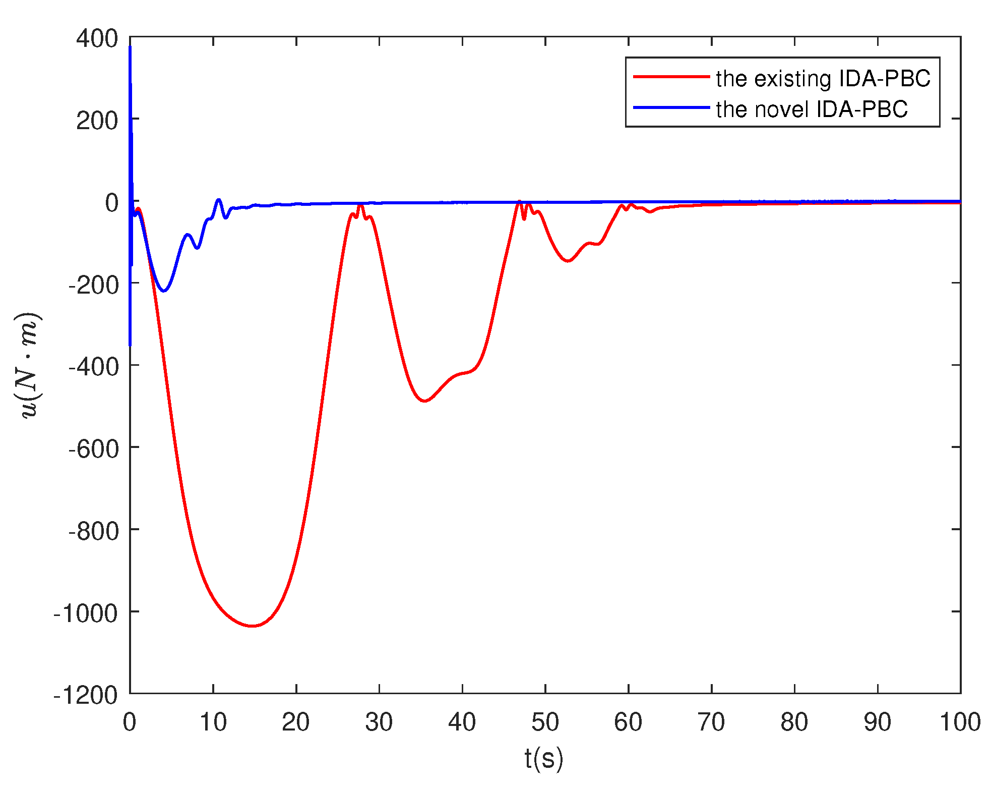
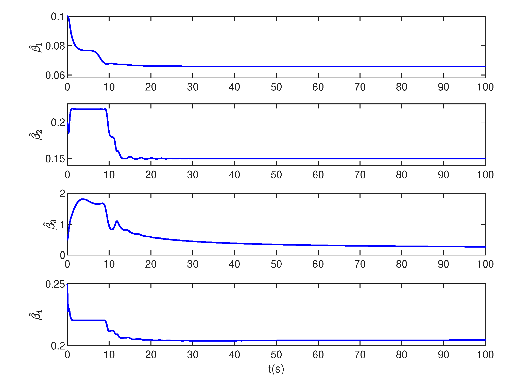
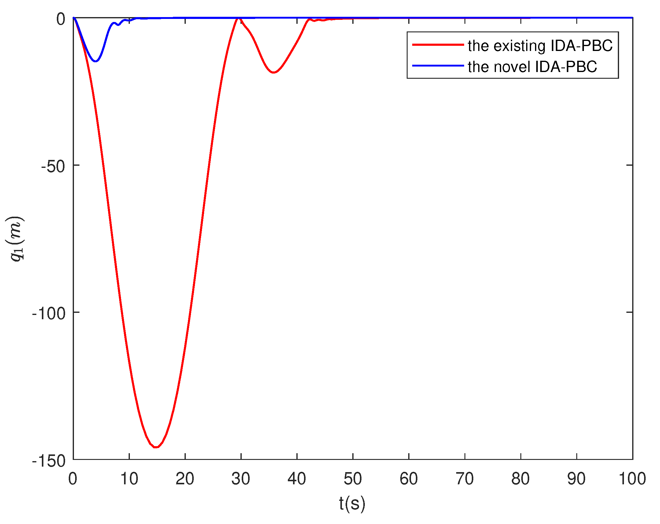
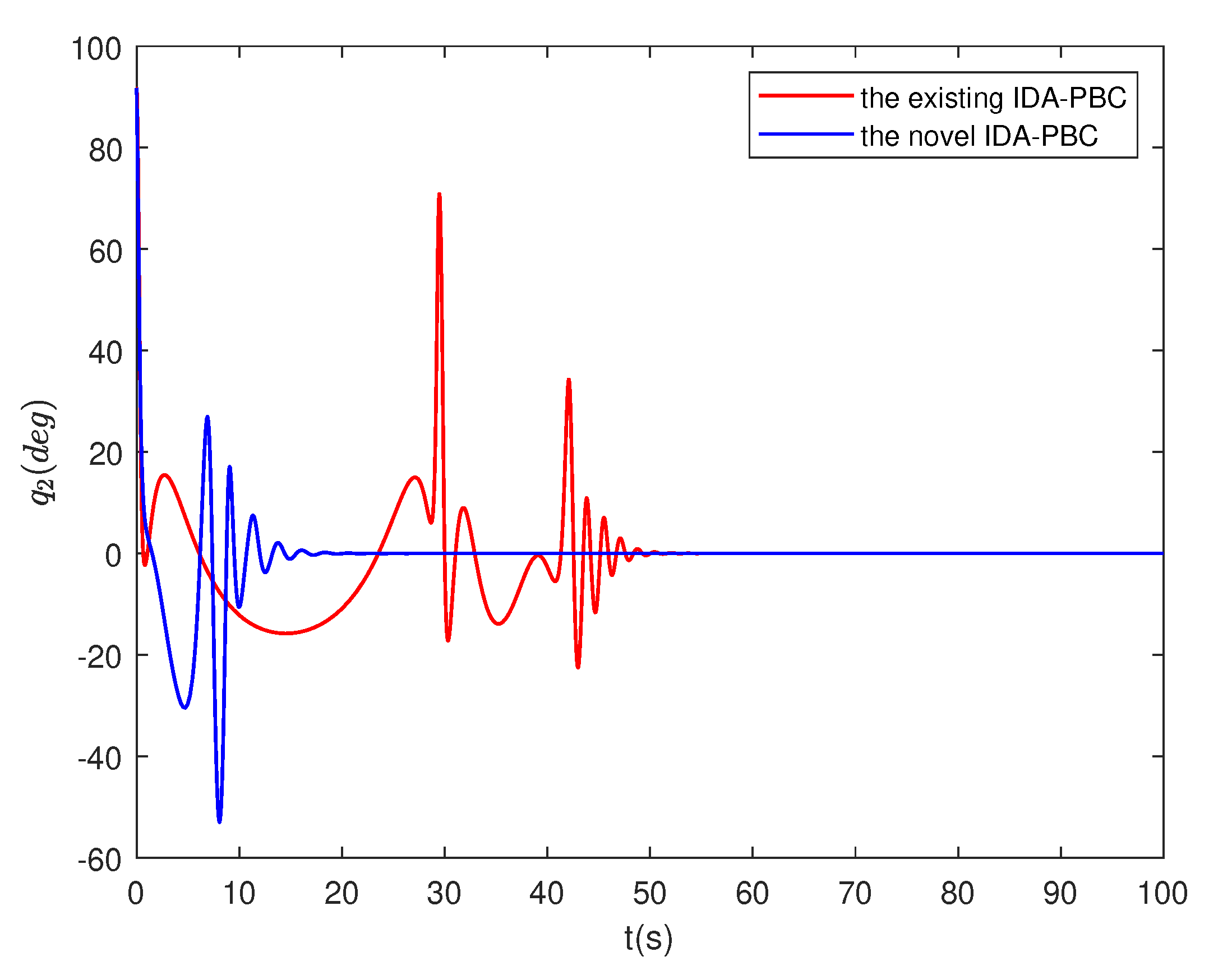
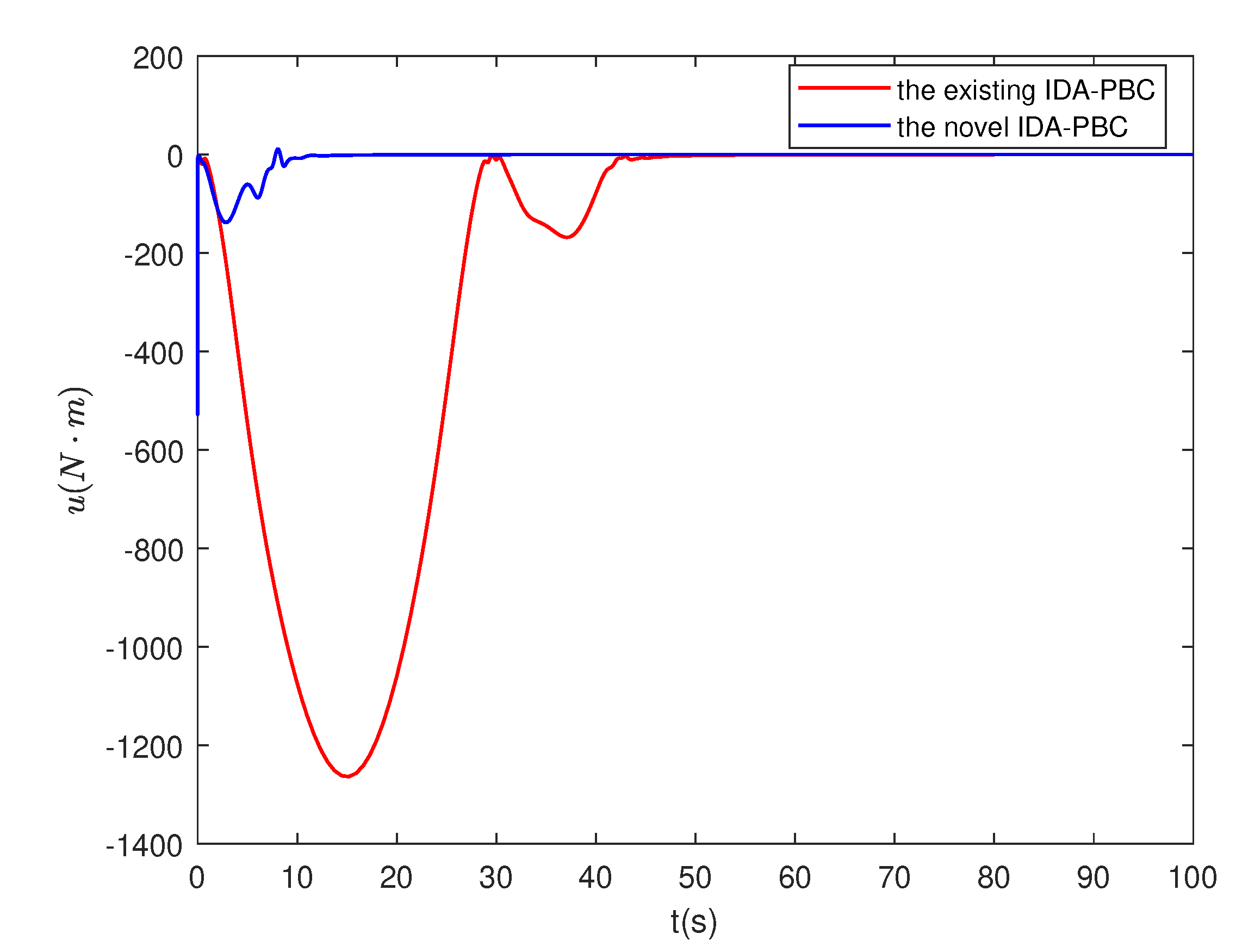
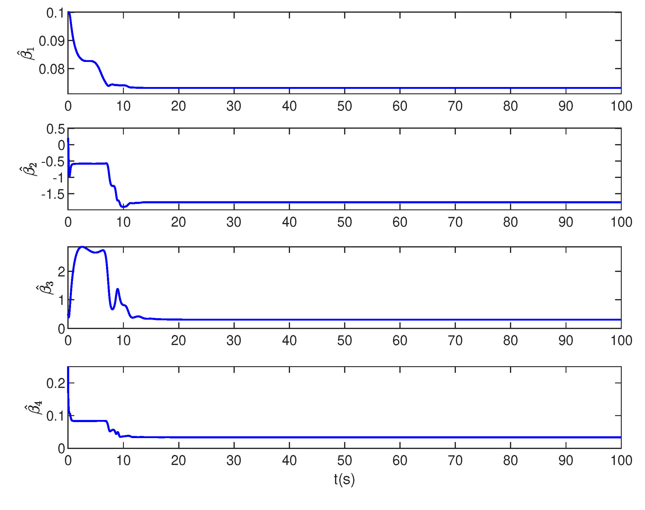
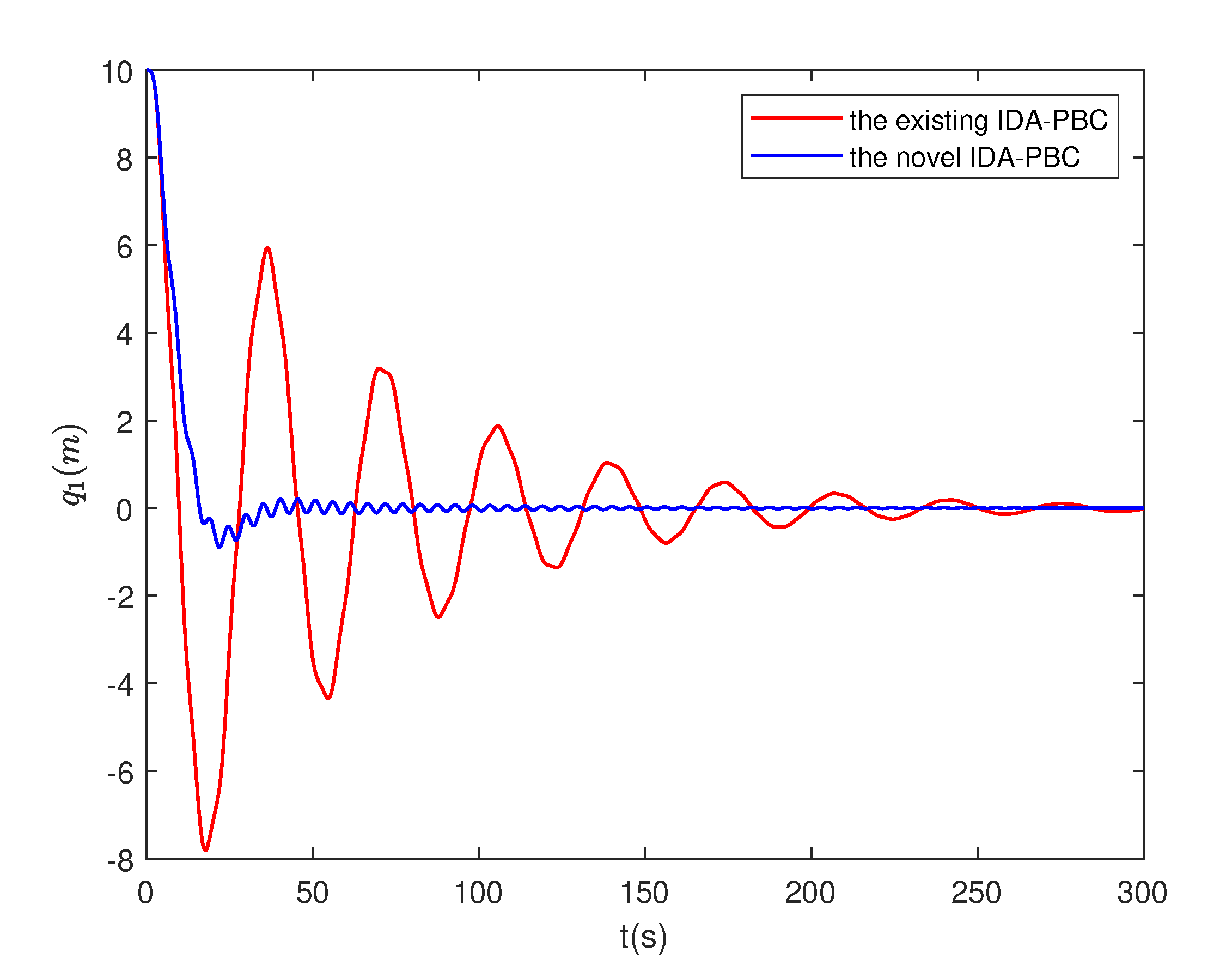
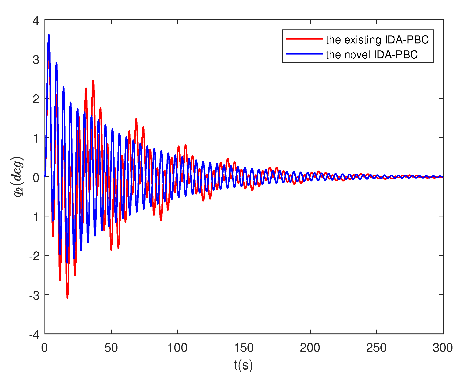
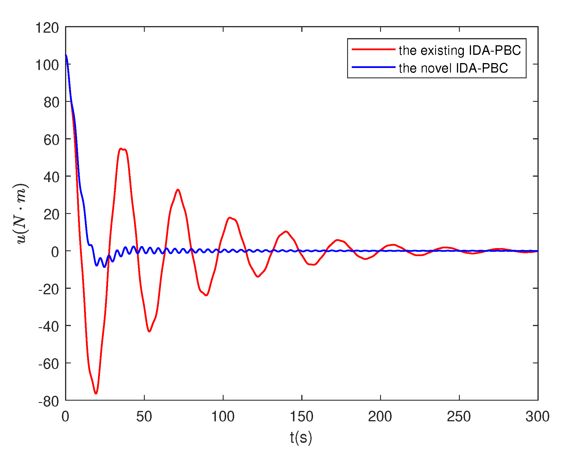
Case 1: The initial conditions are chosen as q , p = 0 , 91 . 7 , 0 , 0 , β ^ 1 , β ^ 2 , β ^ 3 , β ^ 4 = 0.1 , 0.2 , 0.5 , 0.25 , the controller parameters are set to γ 1 = 0.001 , γ 2 = 0.1 , γ 3 = 0.5 , γ 4 = 0.01 , k p = 1 , k v = 20 and the length of the bar is selected as L = 0.5 m . Figure 1, Figure 2, Figure 3 and Figure 4 show the results under Case 1. It can be obviously seen from Figure 1 that using the proposed adaptive controller (29) and (42), the ball reaches the expected position in about 20 s . But under the existing controller (13), the ball gradually stabilizes to the expected position after 70 s . The bar keeps swinging in the range of 41 . 6 , 27 . 6 from 7 s to 30 s , and the swing amplitude decreases significantly after 30 s and the bar gradually reaches a stable state with the proposed adaptive controller in Figure 2. In addition, it can be observed from Figure 3 that the control signal of the proposed adaptive controller is much smaller and settles down faster than the existing controller. As depicted in Figure 4, the estimated values of the four parameters are all convergent, which proves the boundedness of the estimated parameters.
Case 2: The initial conditions are consistent with the selection of the first group, the controller parameters are given as γ 1 = 0.001 , γ 2 = 0.5 , γ 3 = 1 , γ 4 = 0.01 , k p = 1 , k v = 1 and the length of the bar is also selected as L = 0.5 m . The results of this set of conditions are shown in Figure 5, Figure 6, Figure 7 and Figure 8. In terms of these conditions, the position of the ball attains balance in approximately 10 s under the proposed adaptive controller in Figure 5. As shown in Figure 6, the angle of the bar reaches stability in about 20 s under the proposed adaptive controller. However, with the existing controller, the angle of the bar undergos violent oscillation around 30 s and reaches 71 and the bar stabilizes after 50 s . Besides, the control effects are presented in Figure 7. It can be seen from Figure 8 that the estimated values of the four parameters converge after about 10 s .
Case 3: The initial conditions are selected as q , p = 10 , 0 , 0 , 0 , β ^ 1 , β ^ 2 , β ^ 3 , β ^ 4 = 0.1 , 0.2 , 0.05 , 0.25 , the controller parameters are given as γ 1 = 0.01 , γ 2 = 0.2 , γ 3 = 0.1 , γ 4 = 0.01 , k p = 1 , k v = 50 and the length of the bar is chosen as L = 10 m . At about 50 s , the ball oscillates and gradually settles down at the desired position with the proposed adaptive controller in Figure 9. At the same time, under the existing controller, the ball keeps swinging around the equilibrium position. Figure 10 shows that the swing amplitude of the bar gradually becomes smaller and smaller and the angle reaches steady state by the proposed adaptive controller. The vibration amplitude of the control signal significantly decreases under the application of the proposed adaptive controller in Figure 11. It can be seen from Figure 12 that the four estimated parameters are bounded.

5. Conclusions

In this paper, an adaptive control law has been designed for a class of underactuated mechanical systems with matched and unmatched uncertainties. With this controller, the locally asymptotic stability of the underactuated mechanical system is ensured under uncertainties. The estimate values of the unknown terms are placed in the damping injection controller u d i , which simplifies the design of the controller. The locally asymptotic stability of the ball and beam system is proved by using the LaSalle’s invariance principle and approximate linearization.

Author Contributions

Conceptualization, X.L. and H.S.; methodology, X.L. and H.S.; software, H.S.; validation, H.S.; writing—original draft preparation, H.S.; writing—review and editing, X.L., C.L., N.L. All authors have read and agreed to the published version of the manuscript.

Funding

This work is financially sponsored by the Taishan Scholar Project of Shandong Province of China (tsqn201812093), Research on Congestion Modeling and Control for Vehicle Networking (ZR202110110003) and Innovation Team of "intelligent control and energy efficiency management of building equipments" (202228039).

Conflicts of Interest

The authors declare no conflict of interest.

References

  1. Ortega, R.; Spong, M. W.; Gomez-Estern, F.; Blankenstein, G. Stabilization of a class of underactuated mechanical systems via interconnection and damping assignment. IEEE Trans. Automat. Contr. 2002, 47, 1218–1233. [Google Scholar] [CrossRef]
  2. Mahindrakar, A. D.; Astolfi, A.; Ortega, R.; Viola, G. Further constructive results on interconnection and damping assignment control of mechanical systems: the Acrobot example. Int. J. Robust Nonlin. 2010, 16, 671–685. [Google Scholar] [CrossRef]
  3. Rodriguez, H.; Ortega, R.; Escobar, G. A robustly stable output feedback saturated controller for the Boost DC-to-DC converter. In Proceedings of the 38th IEEE Conference on Decision and Control, Phoenix, AZ, USA, 07-10 December 1999. [Google Scholar]
  4. Aoues, S.; Matignon, D.; Alazard, D. Control of a flexible spacecraft using discrete IDA-PBC design. IFAC-PapersOnLine 2015, 48, 188–193. [Google Scholar] [CrossRef]
  5. Acosta, J. A.; Ortega, R.; Astolfi, A.; Mahindrakar, A. D. Interconnection and damping assignment passivity-based control of mechanical systems with underactuation degree one. IEEE Trans. Automat. Contr. 2005, 50, 1936–1955. [Google Scholar] [CrossRef]
  6. Ryalat, M.; Laila, D. S. A simplified IDA-PBC design for underactuated mechanical systems with applications. Eur. J. Control 2016, 27, 1–16. [Google Scholar] [CrossRef]
  7. Zhang, M.; Ortega, R.; Liu, Z.; Su, H. A new family of interconnection and damping assignment passivity-based controllers. Int. J. Robust Nonlin. 2016, 50, 50–65. [Google Scholar] [CrossRef]
  8. Blankenstein, G.; Ortega, R.; Van Der Schaft, A. J. The matching conditions of controlled Lagrangians and IDA-passivity based control. Int. J. Control 2002, 75, 645–665. [Google Scholar] [CrossRef]
  9. Gomez-Estern, F.; Ortega, R.; Rubio, F. R.; Aracil, J. Stabilization of a class of underactuated mechanical systems via total energy shaping. In Proceedings of the 40th IEEE Conference on Decision and Control, Orlando, FL, USA, 04-07 December 2001. [Google Scholar]
  10. Viola, G.; Ortega, R.; Banavar, R.; Acosta, J. A.; Astolfi, A. (2007). Total Energy Shaping Control of Mechanical Systems: Simplifying the Matching Equations Via Coordinate Changes. IEEE Trans. Automat. Contr. 2007, 52, 1093–1099. [Google Scholar] [CrossRef]
  11. Gomez-Estern, F.; Van Der Schaft, A. J. Physical damping in IDA-PBC controlled underactuated mechanical systems. Eur. J. Control 2004, 10, 451–468. [Google Scholar] [CrossRef]
  12. Tiefensee, F.; Monaco, S.; Normand-Cyrot, D. IDA-PBC under sampling for port-controlled hamiltonian systems. In Proceedings of the 2010 American Control Conference, Baltimore, MD, USA, 30 June-02 July 2010. [Google Scholar]
  13. Liu, Z.; Theilliol, D.; Yang, L.; He, Y.; Han, J. Interconnection and Damping Assignment Passivity-Based Control Design Under Loss of Actuator Effectiveness. J. Intell. Robot. Syst. 2020, 100, 29–45. [Google Scholar] [CrossRef]
  14. Donaire, A.; Romero, J. G.; Ortega, R.; Siciliano, B.; Crespo, M. Robust IDA-PBC for underactuated mechanical systems subject to matched disturbances. Int. J. Robust Nonlin. 2017, 27, 1000–1016. [Google Scholar] [CrossRef]
  15. Haddad, N. K.; Chemori, A.; Belghith, S. Robustness enhancement of IDA-PBC controller in stabilising the inertia wheel inverted pendulum: theory and real-time experiments. Int. J. Control 2017, 91, 2657–2672. [Google Scholar] [CrossRef]
  16. Haddad, N. K.; Chemori, A.; Pena, J. J.; Belghith, S. Stabilization of inertia wheel inverted pendulum by model reference adaptive IDA-PBC: From simulation to real-time experiments. In 2015 3rd International Conference on Control, Engineering and Information Technology, Tlemcen, Algeria, 25-27 May 2015. 27 May.
  17. Ryalat, M.; Laila, D. S.; Torbati, M. M. Integral IDA-PBC and PID-like control for port-controlled Hamiltonian systems. In 2015 American Control Conference, Chicago, IL, USA, 01-03 July 2015. 03 July.
  18. Ferguson, J.; Donaire, A.; Ortega, R.; Middleton, R. H. Robust integral action of port-Hamiltonian systems. IFAC-PapersOnLine 2018, 51, 181–186. [Google Scholar] [CrossRef]
  19. Ryalat, M.; Laila, D. S. A Robust IDA-PBC Approach for Handling Uncertainties in Underactuated Mechanical Systems. IEEE Trans. Automat. Contr. 2018, 63, 3495–3502. [Google Scholar] [CrossRef]
  20. Haddad, N. K.; Chemori, A.; Belghith, S. External disturbance rejection in IDA-PBC controller for underactuated mechanical systems: From theory to real time experiments. In 2014 IEEE Conference on Control Applications, Juan Les Antibes, France, 08-10 October 2014. 10 October.
  21. Guerrero-Sanchez, M. E.; Hernandez-Gonzalez, O.; Valencia-Palomo, G.; Mercado-Ravell, D. A.; Lopez-Estrada, F. R.; Hoyo-Montano, J. A. Robust IDA-PBC for under-actuated systems with inertia matrix dependent of the unactuated coordinates: application to a UAV carrying a load. Nonlinear Dyn. 2021, 105, 3225–3238. [Google Scholar] [CrossRef]
  22. Chang, D. E. The Method of Controlled Lagrangians: Energy plus Force Shaping. SIAM J. Control Optim. 2010, 48, 4821–4845. [Google Scholar] [CrossRef]
  23. Delgado, S.; Kotyczka, P. Overcoming the Dissipation Condition in Passivity-based Control for a class of mechanical systems. IFAC Proceedings Volumes 2014, 47, 11189–11194. [Google Scholar] [CrossRef]
  24. Popayan, J. A.; Cieza, O. B.; Reger, J. Adaptive IDA-PBC for a class of UMSs: the IWIP analysis. IFAC-PapersOnLine 2019, 52, 478–483. [Google Scholar] [CrossRef]
  25. Franco, E. IDA-PBC with adaptive friction compensation for underactuated mechanical systems. Int. J. Control 2021, 94, 860–870. [Google Scholar] [CrossRef]
  26. Ryalat, M.; Laila, D. S.; ElMoaqet, H. IDA-PBC with adaptive friction compensation for underactuated mechanical systems. Int. J. Control Autom. Syst. 2021, 19, 864–877. [Google Scholar] [CrossRef]
  27. Liu, Y.; Yu, H. A survey of underactuated mechanical systems. IET Control. Theory Appl. 2013, 7, 921–935. [Google Scholar] [CrossRef]
  28. Hauser, J.; Sastry, S.; Kokotovic, P. Nonlinear control via approximate input-output linearization: the ball and beam example. IEEE Trans. Automat. Contr. 1992, 37, 392–398. [Google Scholar] [CrossRef]
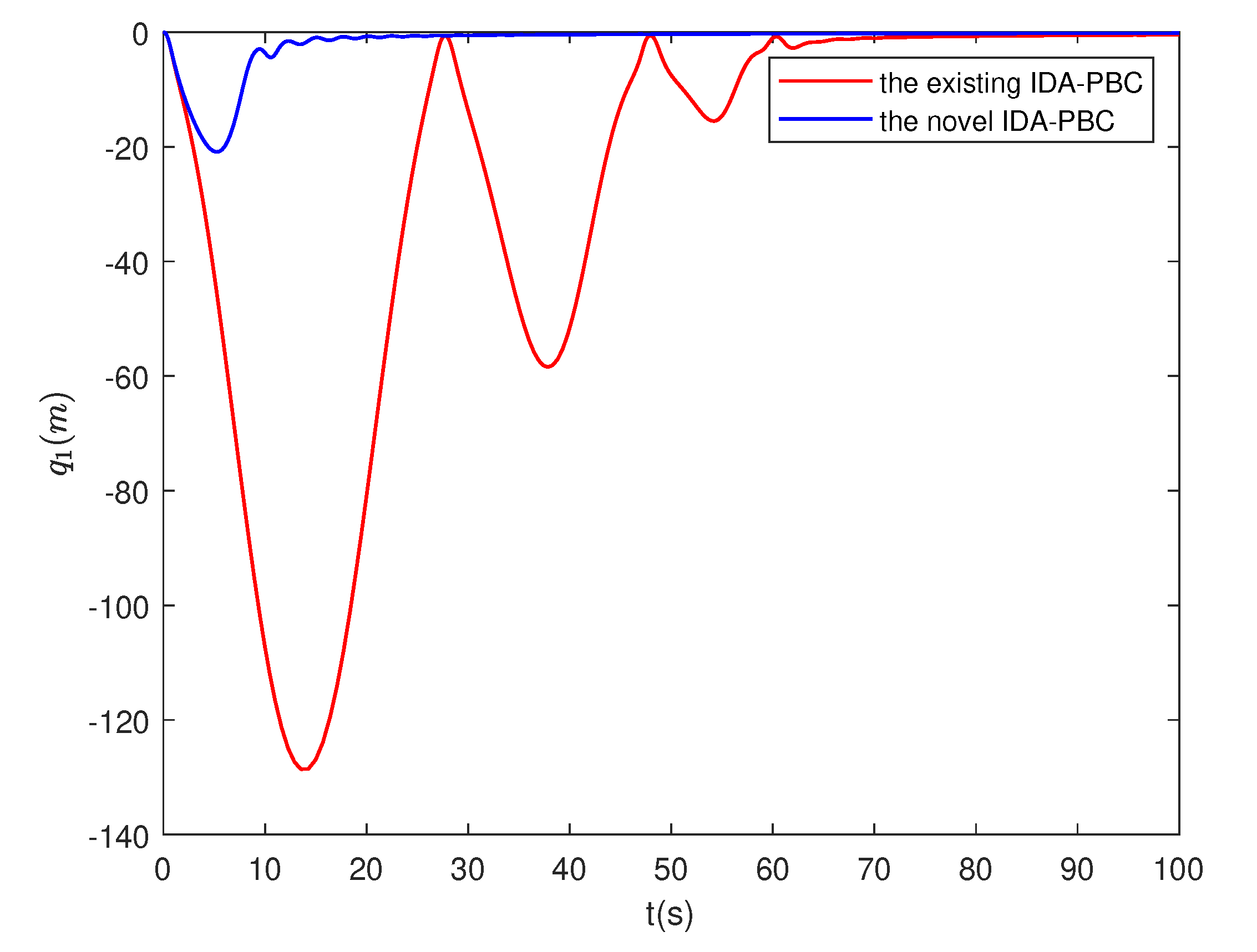
Figure 1. The position of the ball.(Case 1)
Preprints 86188 g001
Figure 2. The angle of the bar.(Case 1)
Preprints 86188 g002
Figure 3. The control signal.(Case 1)
Preprints 86188 g003
Figure 4. The estimated parameters.(Case 1)
Preprints 86188 g004
Figure 5. The position of the ball.(Case 2)
Preprints 86188 g005
Figure 6. The angle of the bar.(Case 2)
Preprints 86188 g006
Figure 7. The control signal.(Case 2)
Preprints 86188 g007
Figure 8. The estimated parameters.(Case 2)
Preprints 86188 g008
Figure 9. The position of the ball.(Case 3)
Preprints 86188 g009
Figure 10. The angle of the bar.(Case 3)
Preprints 86188 g010
Figure 11. The control signal.(Case 3)
Preprints 86188 g011
Figure 12. The estimated parameters.(Case 3)
Preprints 86188 g012
Disclaimer/Publisher’s Note: The statements, opinions and data contained in all publications are solely those of the individual author(s) and contributor(s) and not of MDPI and/or the editor(s). MDPI and/or the editor(s) disclaim responsibility for any injury to people or property resulting from any ideas, methods, instructions or products referred to in the content.
Copyright: This open access article is published under a Creative Commons CC BY 4.0 license, which permit the free download, distribution, and reuse, provided that the author and preprint are cited in any reuse.
Prerpints.org logo

Preprints.org is a free preprint server supported by MDPI in Basel, Switzerland.

Subscribe

© 2024 MDPI (Basel, Switzerland) unless otherwise stated