Submitted:
28 September 2023
Posted:
29 September 2023
You are already at the latest version
Abstract
Keywords:
1. Introduction
2. Modelling and Experiment
2.1. Equations of State for DEAs
2.2. Charge-control & leakage current
3. Method
3.1. Fabrication of Spring Rolls
3.2. Experimental Setup
4. Results
4.1. Static Response
4.2. Dielectric properties of membrane
4.3. Dynamic Response
5. Discussion
6. Conclusions
Author Contributions
Funding
Data Availability Statement
Acknowledgments
Conflicts of Interest
References
- Brochu, P.; Pei, Q. Advances in Dielectric Elastomers for Actuators and Artificial Muscles. Macromol. Rapid Commun. 2009, 31, 10–36. [CrossRef]
- Chen, Y.; Xu, S.; Ren, Z.; Chirarattananon, P. Collision Resilient Insect-Scale Soft-Actuated Aerial Robots With High Agility. IEEE Trans. Robot. 2021, 37, 1752–1764. [CrossRef]
- Pelrine, R.; Kornbluh, R.; Pei, Q.; Joseph, J. High-Speed Electrically Actuated Elastomers with Strain Greater Than 100%. Science 2000, 287, 836–839. [CrossRef]
- Pelrine, R.; Kornbluh, R.; Kofod, G. High-Strain Actuator Materials Based on Dielectric Elastomers. Adv. Mater. 2000, 12, 1223–1225. [CrossRef]
- Zhang, J.; Chen, H.; Tang, L.; Li, B.; Sheng, J.; Liu, L. Modelling of spring roll actuators based on viscoelastic dielectric elastomers. Appl. Phys. A 2015, 119, 825–835. [CrossRef]
- Lau, G.-K.; Shiau, L.-L.; Chua, S.-L. Effects of Thinner Compliant Electrodes on Self-Clearability of Dielectric Elastomer Actuators. Actuators 2020, 9, 121. [CrossRef]
- Lochmatter, P.; Kovacs, G.; Wissler, M. Characterization of dielectric elastomer actuators based on a visco-hyperelastic film model. Smart Mater. Struct. 2007, 16, 477–486. [CrossRef]
- F.-b. Zhu, C.-l. Zhang, J. Qian and W.-q. Chen, “Mechanics of dielectric elastomers: materials, structures, and devices,” Journal of Zhejiang University-SCIENCE A (Applied Physics & Engineering), vol. 17, no. 1, pp. 1-21, 2016. [CrossRef]
- Zhang, J.; Chen, H.; Li, B.; McCoul, D.; Pei, Q. Coupled nonlinear oscillation and stability evolution of viscoelastic dielectric elastomers. 2015, 11, 7483–7493. [CrossRef]
- D. Q. Tran, J. Li, F. Xuan and T. Xiao, “Viscoelastic effects on the actuation performance of a dielectric elastomer actuator under different equal, un-equal biaxial pre-stretches,” Materials Research Express, vol. 5, no. 1, pp. 1-12, 2018. [CrossRef]
- W. Lai, “Characteristics of dielectric elastomers and fabrication of dielectric elastomer actuators for artificial muscle application,” Iowa State University, Ames, 2011.
- Britannica, “Dielectrics, polarization, and electric dipole moment,” Britannica, 2023. [Online]. Available: https://www.britannica.com/science/electricity/Dielectrics-polarization-and-electric-dipole-moment. [Accessed 7 2 2023].
- Britannica, “Molecular structure and charge distribution,” Britannica, 2023. [Online]. Available: https://www.britannica.com/science/liquid-state-of-matter/Molecular-structure-and-charge-distribution. [Accessed 7 2 2023].
- Löwe, C.; Zhang, X.; Kovacs, G. Dielectric Elastomers in Actuator Technology. Adv. Eng. Mater. 2005, 7, 361–367. [CrossRef]
- Wang, H.; Li, L.; Zhu, Y.; Yang, W. Analysis and application of a rolled dielectric elastomer actuator with two degrees of freedom. Smart Mater. Struct. 2016, 25. [CrossRef]
- Li, L.; Godaba, H.; Ren, H.; Zhu, J. Bioinspired Soft Actuators for Eyeball Motions in Humanoid Robots. IEEE/ASME Trans. Mechatronics 2018, 24, 100–108. [CrossRef]
- Pei, Q.; Rosenthal, M.; Stanford, S.; Prahlad, H.; Pelrine, R. Multiple-degrees-of-freedom electroelastomer roll actuators. Smart Mater. Struct. 2004, 13, N86–N92. [CrossRef]
- Heng, K.-R.; Ahmed, A.S.; Shrestha, M.; Lau, G.-K. Strong dielectric-elastomer grippers with tension arch flexures. SPIE Smart Structures and Materials + Nondestructive Evaluation and Health Monitoring; pp. 101631Z–101631Z-8. [CrossRef]
- van Kessel, R.; Bauer, P.; A Ferreira, J. Electrical modeling of cylindrical dielectric elastomer transducers. Smart Mater. Struct. 2021, 30, 035021. [CrossRef]
- Huang, R.; Suo, Z. Electromechanical phase transition in dielectric elastomers. Proceedings of the Royal Society 2011, 468, 1014–1040. [CrossRef]
- Goulbourne, N.; Mockensturm, E.; Frecker, M. A Nonlinear Model for Dielectric Elastomer Membranes. J. Appl. Mech. 2005, 72, 899–906. [CrossRef]
- E. Yang, M. Frecker and E. Mockensturm, “Viscoelastics model of dielectric elasmtomer membranes,” Proc. SPIE 5759, Smart Structures and Materials, vol. 5759, no. 1, pp. 82-92, 2005. [CrossRef]
- T. Lu, J. Huang, C. Jordi, G. Kovacs, R. Huang, D. R. Clarkeb and Z. Suo, “Dielectric elastomer actuators under equal-biaxial forces, uniaxial forces, and uniaxial constraint of stiff fibers,” Soft Matter, vol. 8, no. 1, pp. 6167-6173, 2012. [CrossRef]
- Foo, C.C.; Cai, S.; Koh, S.J.A.; Bauer, S.; Suo, Z. Model of dissipative dielectric elastomers. J. Appl. Phys. 2012, 111. [CrossRef]
- J. Zhang, H. Chen, J. Sheng, L. Liu and B. Li, “Leakage current of a charge-controlled dielectric elastomer,” Proceedings of SPIE, vol. 9056, no. 1, pp. 1-10, 2014. [CrossRef]
- J. McPherson, A. S. J. Kim, H. Mogul and J. Rodriguez, “Proposed universal relationship between dielectric breakdown and dielectric constant,” Digest. International Electron Devices Meeting, vol. 1, no. 1, pp. 633-636, 2002. [CrossRef]
- Q. Tan, P. Irwin and Y. Cao, “Advanced Dielectrics for Capacitors,” Transactions on Fundamentals and Materials, vol. 126, no. 11, pp. 1153-1159, 2006. [CrossRef]
- Teh, Y.S.; Koh, S.J.A. Giant continuously-tunable actuation of a dielectric elastomer ring actuator. Extreme Mech. Lett. 2016, 9, 195–203. [CrossRef]
- Romasanta, L.; Lopez-Manchado, M.; Verdejo, R. Increasing the performance of dielectric elastomer actuators: A review from the materials perspective. Prog. Polym. Sci. 2015, 51, 188–211. [CrossRef]
- Zhao, X.; Suo, Z. Electrostriction in elastic dielectrics undergoing large deformation. J. Appl. Phys. 2008, 104, 123530. [CrossRef]

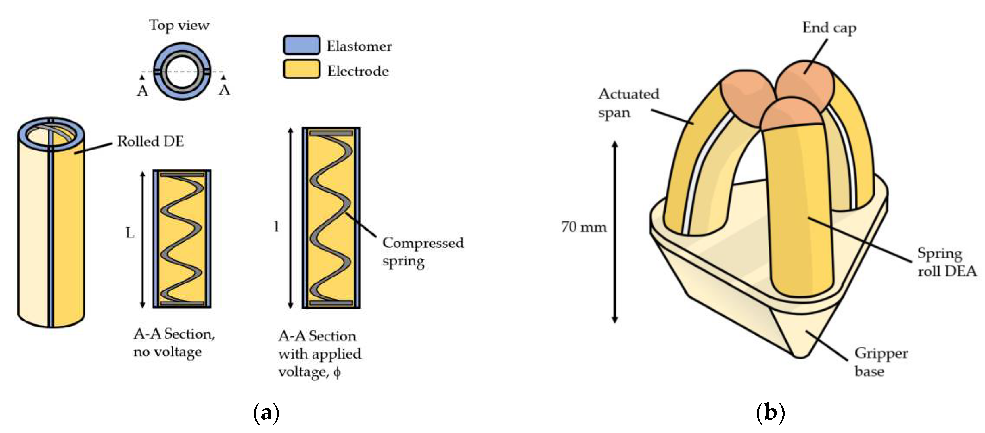


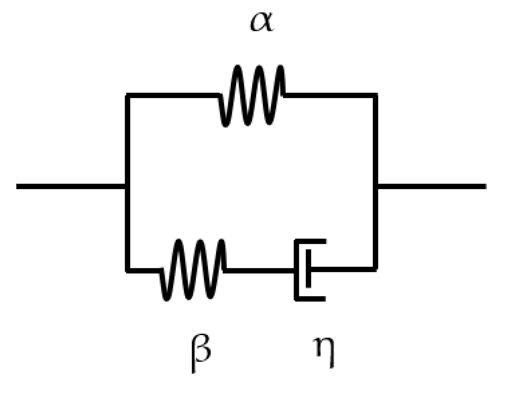
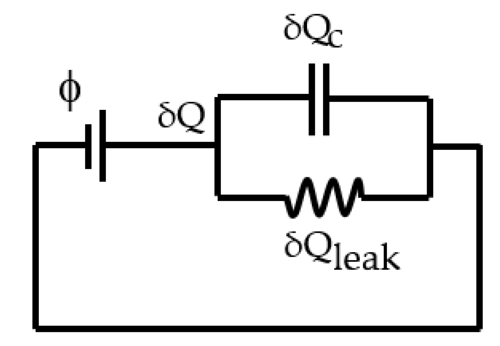
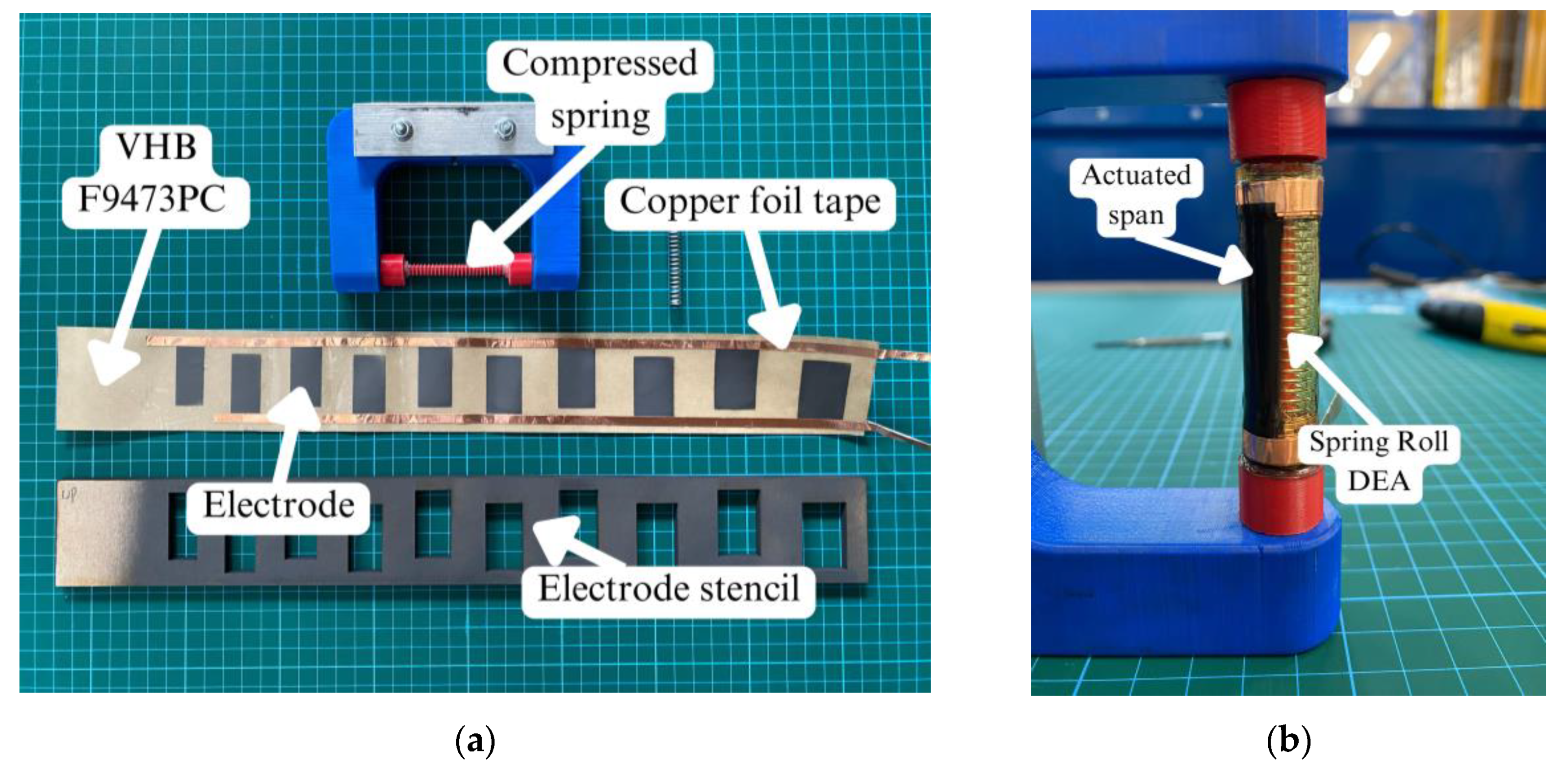
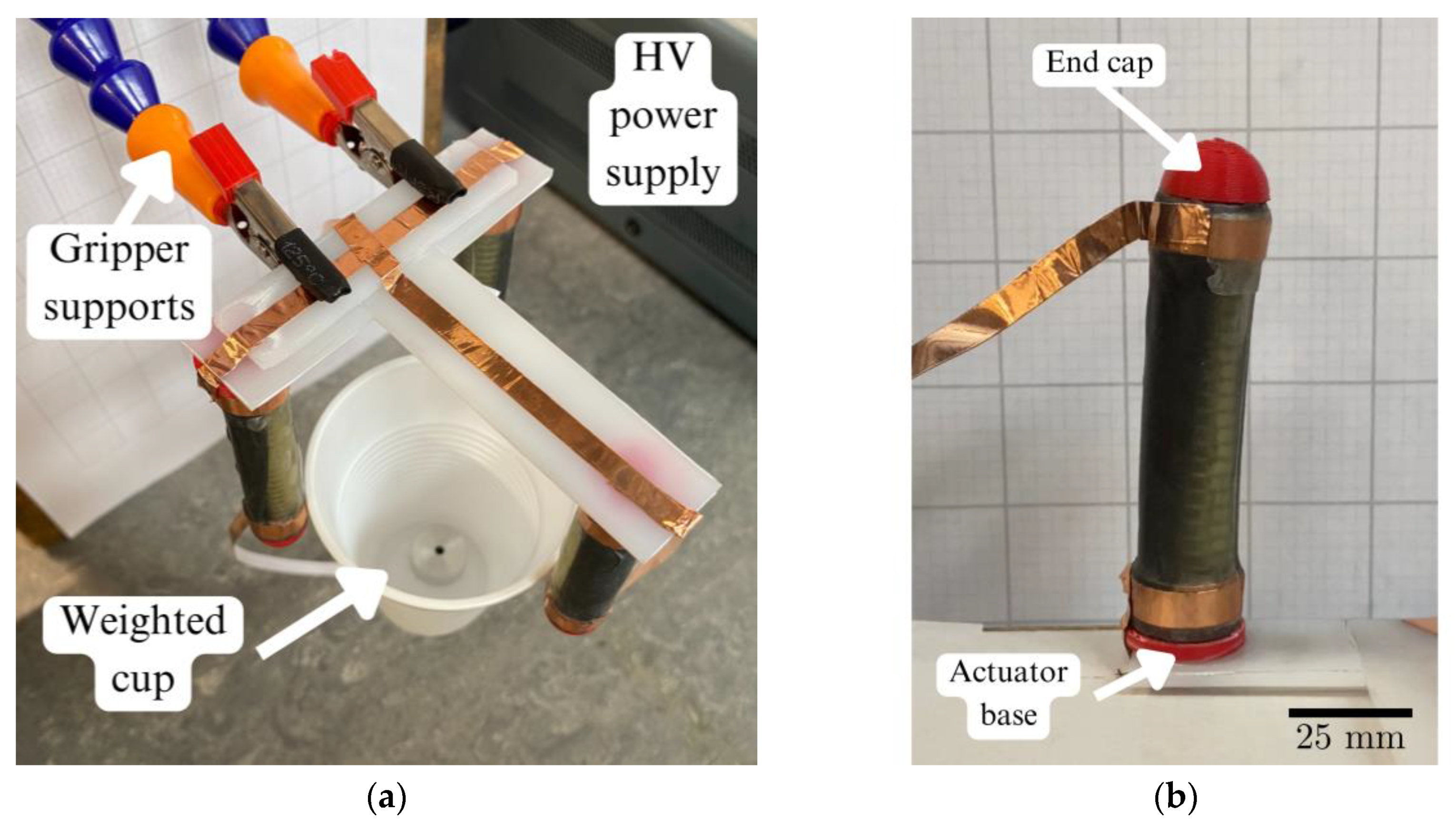
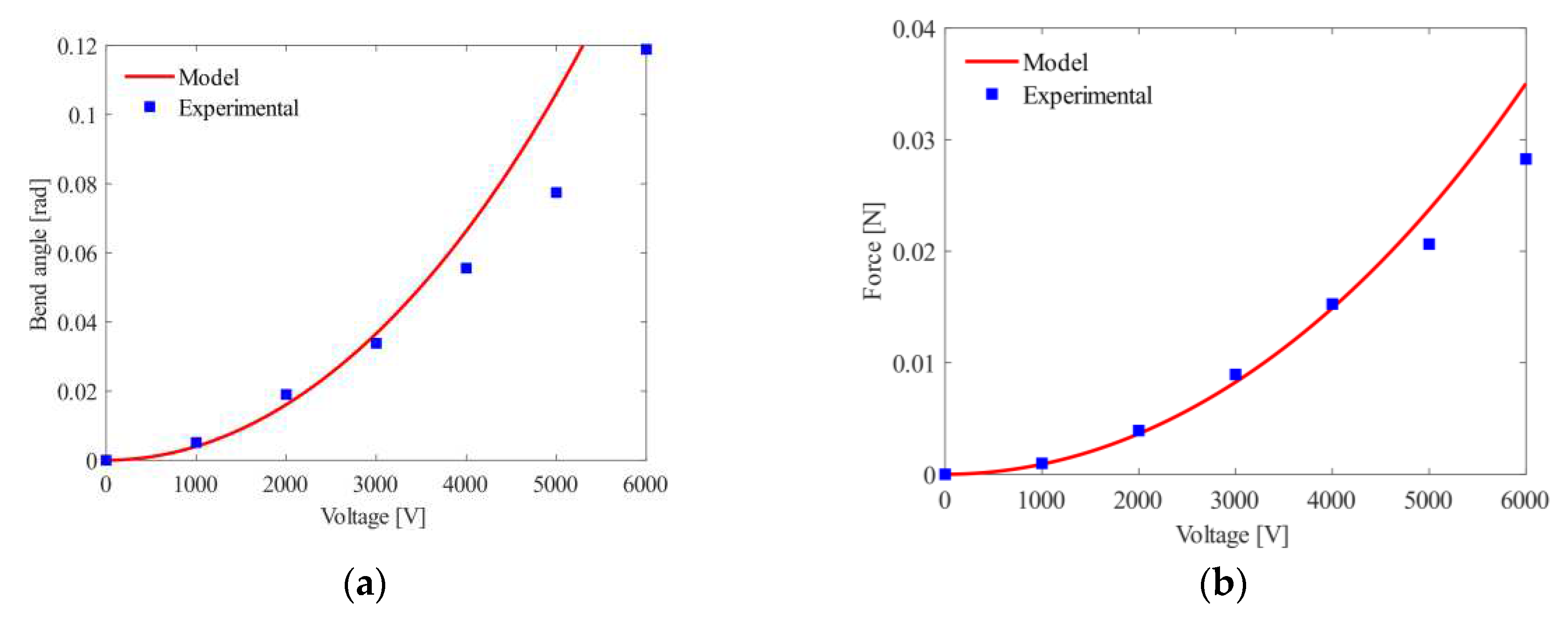
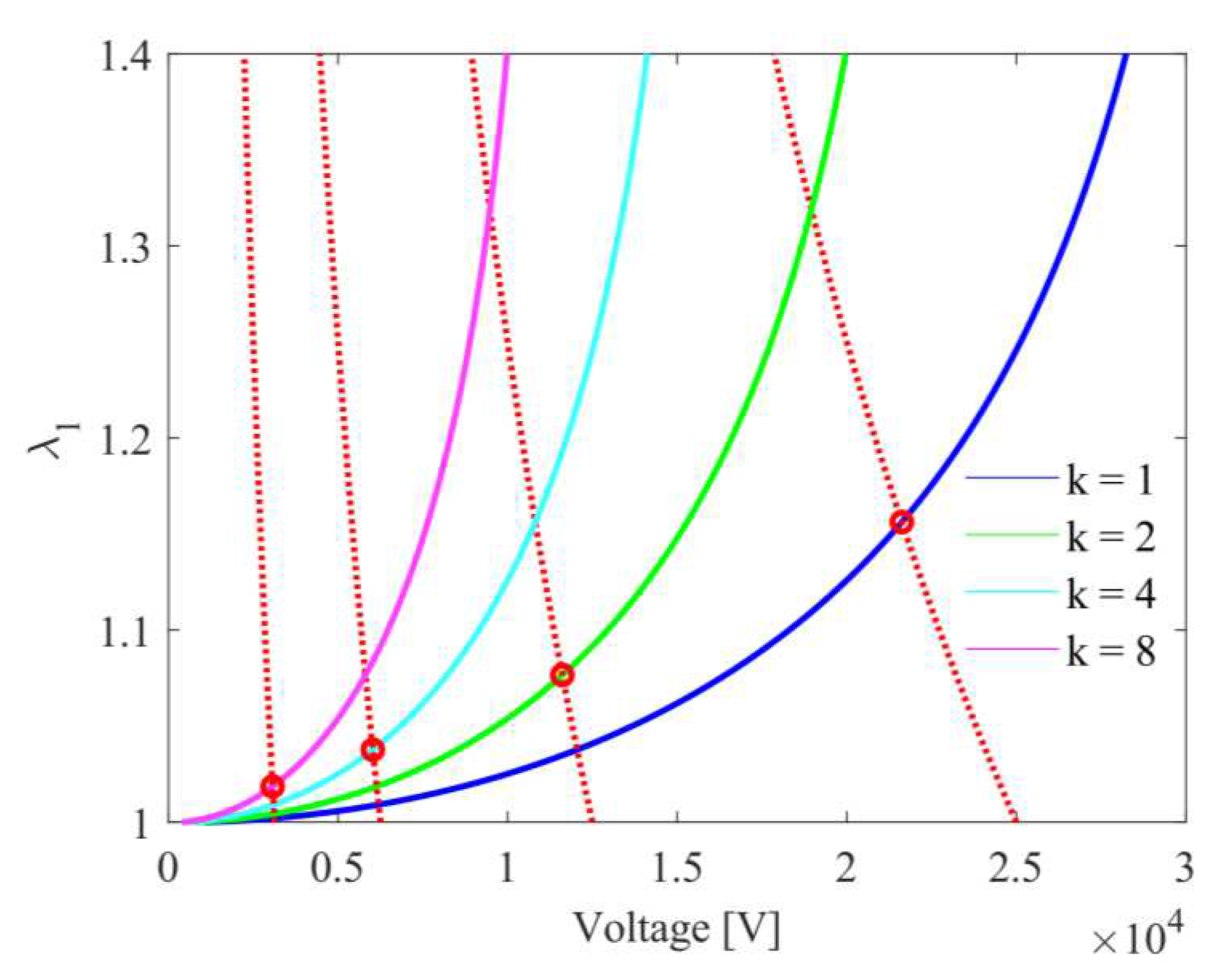
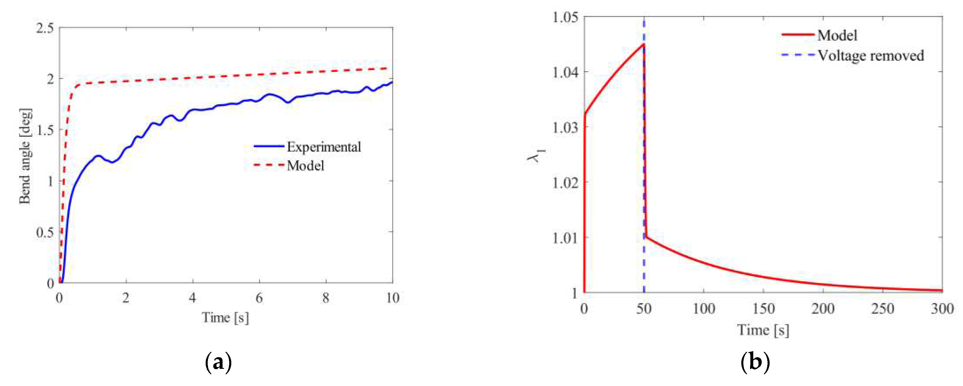
| Material parameter | Value |
|---|---|
| 115 | |
| 70 | |
| 16000 | |
| 45000 | |
| 6 |
| Parameter | 2-DOF roll (Version 1), 2004 [17] | 2-DOF roll, 2016 [15] | This work |
| Actuator mass | 29 g | - | 10 g |
| Actuator length | 68 mm | 40 mm | 70 mm |
| Dielectric elastomer (pre-stretch ratio) | VHB-4910 | VHB-4910 (3, 5) | VHB-F9473PC (1.03, 1) |
| Maximum operating voltage | 5.5 kV | 5 kV | 6 kV |
| Maximum stroke | - | 8.4 mm | - |
| Maximum bending angle | 60 ° | 75.3 ° | 6.8 ° |
| Maximum force | 1.68 N | 0.7 N | 0.03 N |
| No. of rolls | 20 | 14 | 10 |
| Dashpot fully extended | Yes | Yes | No |
Disclaimer/Publisher’s Note: The statements, opinions and data contained in all publications are solely those of the individual author(s) and contributor(s) and not of MDPI and/or the editor(s). MDPI and/or the editor(s) disclaim responsibility for any injury to people or property resulting from any ideas, methods, instructions or products referred to in the content. |
© 2023 by the authors. Licensee MDPI, Basel, Switzerland. This article is an open access article distributed under the terms and conditions of the Creative Commons Attribution (CC BY) license (http://creativecommons.org/licenses/by/4.0/).


