Preprint
Article

Optimal Adaptive Continuous Barrier Function Design for Non-linear Systems Under Model Uncertainty and External Disturbance using Terminal Sliding Mode Control

Altmetrics

Downloads

197

Views

84

Comments

0

Submitted:

02 October 2023

Posted:

03 October 2023

You are already at the latest version

Alerts
Abstract
This study presents an innovative approach named Optimal Adaptive Continuous Barrier Function Terminal Sliding Mode Control (OACBF-TSMC) approach with a novel switching manifold, to control mathematical model of nonlinear systems under model uncertainties and external disturbances. The proposed OACBF-TSMC approach combines the advantages of adaptive control, continuous barrier functions, and terminal sliding mode control to achieve robust stability of the mathematical model of nonlinear systems, and by using a genetic algorithm that tries to optimize the controller parameters as much as possible so that the proposed controller is the most to have efficiency and performance. The proposed method is designed to address the challenges of systems and provide superior performance in terms of stabilization accuracy, disturbance rejection, and robustness against uncertainties. However, the critical challenge facing the proposed controller is the complete elimination of the chattering phenomenon, which is the most important problem of ordinary sliding mode controllers. The simulation results show that the system trajectories in the proposed approach have converged to the origin with minimal overshoot and under-shoot in a finite time; In addition, the chattering problem in the control inputs has been well eliminated, which makes the proposed method suitable for various systems, including chaotic systems, energy sources, and distributed production systems. Furthermore, the OACBF-TSMC approach has the potential to enhance the stability and reliability of control systems, contributing to the integration of the system states.
Keywords: 
Subject: Engineering  -   Control and Systems Engineering

1. Intoduction

Mathematical nonlinear systems are complex systems that exhibit non-linear behavior, which means that the output of the system is not proportional to the input. These systems are found in many areas of science and engineering, including physics, chemistry, biology, economics, and engineering. Nonlinear systems can be difficult to control because they often exhibit chaotic behavior and can be sensitive to small changes in initial conditions [1,2]. Controlling nonlinear systems is important for several reasons. First, many real-world systems are inherently nonlinear, so understanding how to control them is essential for designing effective solutions. For example, controlling the temperature of a chemical reactor or the speed of a motor requires understanding how to control nonlinear dynamics [3]. Secondly, nonlinear systems can exhibit unstable behavior that can lead to catastrophic consequences if left unchecked. For example, an uncontrolled chemical reaction can result in an explosion or fire. Similarly, an uncontrolled aircraft can crash due to unstable flight dynamics [4,5]. Finally, controlling nonlinear systems is important for optimizing performance. Many engineering applications require optimizing a system's performance while minimizing energy consumption or other costs. Understanding how to control nonlinear dynamics can help engineers design more efficient and effective solutions [6]. In conclusion, controlling mathematical nonlinear systems is essential for designing effective solutions in many areas of science and engineering. Nonlinear dynamics can be difficult to control, but understanding how to do so is essential for optimizing performance and avoiding catastrophic consequences.
Various control techniques have been proposed for mathematical model of nonlinear systems, including conventional PI controllers [7,8,9], fractional order PID controllers [10], H controllers based on linear matrix inequality (LMI) [11,12], fuzzy logic controllers [13,14], and model predictive controllers [15,16]. However, these methods may not be effective in handling uncertainties and disturbances that are common in nonlinear systems [17]. Recently, a robust control method for uncertainties has been used to control the nonlinear systems called Sliding Mode Control (SMC) [18,19,20,21]. However, most conventional SMC laws suffer from the undesirable phenomenon of chattering, which is caused by the discontinuity of the signum function in the controller signals [3]. Nevertheless, there are several methods of removing the chattering phenomenon in conventional SMC, including the boundary layer approach: This method involves introducing a small boundary layer around the sliding surface to smooth out the control signal and reduce chattering [22,23]. High-gain approach: This method involves increasing the gain of the SMC to reduce chattering. However, this can lead to instability and overshoot [24,25]. Integral SMC: This method involves adding an integral term to the SMC to eliminate steady-state error and reduce chattering [26,27]. Adaptive sliding mode control (ASMC): This method involves adjusting the parameters of the SMC based on system dynamics to reduce chattering [28,29]. Fuzzy logic-based SMC: This method involves using fuzzy logic to adjust the switching gain of the SMC, which can reduce chattering and improve performance [30,31]. Nonlinear disturbance observer-based SMC: This method involves using a nonlinear disturbance observer to estimate and compensate for disturbances in the system, which can reduce chattering and improve robustness [32].
Among the above techniques, adaptive control is an effectual and practical technique to overcome the uncertainty of parameters in practical nonlinear systems and it has worked well in different aspects in solving issues such as input saturation, unmeasurable mode, and improving controller performance [33,34,35]. Nevertheless, for a system with unknown uncertainty terms, conventional adaptive control cannot absolutely assure optimal and great control efficiency [36]. However, Adaptive Terminal sliding mode control (TSMC) is an effective and robust control strategy for regulating dynamic systems. Its ability to handle nonlinear systems and adapt to changes in their behavior makes it an ideal choice for various applications where precise control is required [20,37]. TSMC is a robust control technique that has gained significant attention in recent years due to its ability to provide high-performance control in the presence of uncertainties and disturbances [38,39]. TSMC is a type of SMC that aims to drive the system state onto a predefined sliding surface, where it remains for the rest of the control process [40]. The main advantage of TSMC over traditional SMC is that it ensures finite-time convergence to the sliding surface, which means that the system reaches a stable state within a finite time period [41]. This feature makes TSMC particularly useful for applications where fast and accurate tracking is required, such as robotics, aerospace, and automotive systems [42]. TSM has also been applied successfully in various other fields, including power electronics, renewable energy systems, and biomedical engineering [43,44,45]. In this article, the theory of TSMC and its applications in the field of mathematical model of nonlinear systems are discussed. It will also highlight some challenges that need to be addressed for the further development of this promising control technique.
This paper proposes a novel control strategy called Optimal Adaptive Continues Barrier Function Terminal Sliding Mode Controller (OACBF-TSMC), which combines adaptive control with SMC to achieve robust stability of a mathematical model of nonlinear systems. The OACBF-TSMC approach is based on the concept of barrier functions, which are mathematical functions that impose constraints on system states to prevent them from entering unsafe regions. The controller design involves constructing a barrier function that ensures the system's frequency remains within a safe range while minimizing the tracking error between the desired and actual frequency values [46,47]. The SMC technique is then used to achieve fast convergence and robustness against disturbances by introducing a discontinuous control law that drives the system towards the sliding surface. The adaptive component of AOCBF-TSMC allows for online tuning of controller parameters based on real-time measurements of system states. This feature enables the controller to adapt to changes in system dynamics and uncertainties without requiring prior knowledge of system parameters. Moreover, OACBF-TSMC can handle nonlinearities and time-varying disturbances that are common in nonlinear systems. Ultimately, the proposed method tunes controller parameters using the genetic algorithm to achieve the best and most optimal control performance. In conclusion, the OACBF-TSMC approach offers a promising solution for the stabilization of nonlinear systems by combining adaptive control with SMC and barrier functions. The controller's ability to handle uncertainties, nonlinearities, and disturbances makes it suitable for practical nonlinear systems.
The structure of the rest of this article is as follows: The second part describes the structure of the mathematical model of nonlinear systems in the presence of model uncertainties and external disturbances. Then, in the third part, the design of a robust finite time controller is discussed to stabilize the mathematical model of nonlinear systems using mathematical relationships. Section 4 presents simulation results to validate the effectiveness of the proposed controller. Finally, Section 5 concludes the paper and discusses future research directions.

2. Problem formulation

In general, the mathematical model of disturbed nonlinear systems is considered as follows [31,48]:
ϑ ˙ t = H ϑ t + G τ t + W t ,
so that ϑ t R n are the state trajectories of the nonlinear system Eq. (1), τ t R n is the control input signals, W t is equal to F t × D ( t ) , D t R represents the external disturbance that l 1 is upper bound of D t so that D t l 1 , F t , H and G are matrices with fixed components.
Considering ϑ ˙ = ϑ 1 T ϑ 1 T T , Eq. (1) can be converted into the following state space equation:
ϑ ˙ 1 ( t ) = H 11 ϑ 1 ( t ) + H 12 ϑ 2 ( t ) + 1 M D ( t ) , ϑ ˙ 2 ( t ) = H 21 ϑ 1 ( t ) + H 22 ϑ 2 ( t ) + G 2 τ ( t ) ,
where ϑ 1 T and ϑ 2 T represent the states of the nonlinear system, τ t represents the external disturbance, M is a positive constant parameter, H 11 ,   H 12 ,   H 21 ,   H 22 and G 2 represent matrices of appropriate dimensions.
Assumption 1. 
C 1  represents the upper bound of unknown external disturbance  D  , with  D C 1 .
Lemma 1.  
Consider if  ϑ ƴ R n  and  ϑ ˙ = θ x ,   θ   : R n R n  a continuous system on the region  ƴ  as the open neighborhood of origin and local Lipschitz at  ƴ 0  and   θ 0 = 0 . Furthermore, assume that there is a continual Lyapunov function  L : ƴ R  with the following qualifications.
(a)  L  represents a positive-definite function;
(b)  L ˙  is negative-definite on   ƴ { 0 } ;
(c) There are positive real values  m  and  0 < a < 1 , and a neighborhood  Ɲ ƴ  of origin such that:
L ˙ + m L a 0 .
Therefore, the origin can be introduced as is a stable finite-time equilibrium point for the  ϑ ˙ = θ x .
Based on lemma 1, the Lyapunov function  L : R  converges to origin in a finite time for the initial time  t 0   . As a result, it is gained:
t s = t 0 + L 1 a ( t 0 ) £ ( 1 a )
so that  £  indicates a positive and constant coefficient and  t s  indicates the settling time of the system.

3. Control design

In this section, an ACBF-TSMC is suggested to the mathematical model of nonlinear systems in the presence of uncertainties and perturbations.
For this propose let the switching function for system Eq. (2) be defined as
σ ( t ) = A ϑ 1 ( t ) + B ϑ 2 ( t ) ,
so that A and B represent positive and constant matrices. However, when the switching manifold σ ( t ) = 0 is reached, Eq. (5) follows:
ϑ 2 ( t ) = B 1 A ϑ 1 ( t ) .
By using Eqs. (2) and (6), the equation of sliding manifold is obtained as
ϑ ˙ 1 ( t ) = H 11 H 12 B 1 A ϑ 1 ( t ) + 1 M D .
By taking the derivative from sliding manifold Eq. (5) the following equation is obtained as
σ ˙ = A ϑ ˙ 1 + B ϑ ˙ 2 = A H 11 H 12 B 1 A ϑ 1 + B H 21 H 22 B 1 A ϑ 1 + G 2 τ + 1 M A D .
Theorem 1. 
Consider the mathematical model of the nonlinear system Eq. (2) and the sliding manifold Eq. (5). Furthermore, assuming that C 1 ( t ) represents the upper bound of unknown external disturbance D ( t ) , therefore, C ^ ( t ) can be defined as an estimate of C 1 ( t ) as the following Equation:
C ^ ˙ ( t ) = ρ σ ( t ) ,
so that  ρ > 0 . Next, the terminal adaptive sliding mode control law for nonlinear system Eq. (2) is obtained as
τ ( t ) = B G 2 A H 11 A H 12 B 1 A + B H 21 B H 22 B 1 A ϑ 1 ( t ) + C ^ ( t )   s g n   σ ( t ) .
Therefore, the trajectories of the nonlinear system Eq. (2) converge to the sliding manifold Eq. (5) in a finite time.
Proof. 
Let us define a positive definite Lyapunov function as
L = 1 2 α C ~ ( t ) 2 + 1 2 σ ( t ) 2 ,
so that C ~ ( t ) = C ^ ( t ) C 1 ( t ) and α represents a scaler parameter with range 1 < α < ρ . By taking the derivative from Eq. (11) and using sliding manifold Eq. (5), the following equation is obtained.
L ˙ = α C ~ ( t ) C ^ ˙ ( t ) + σ ( t ) σ ˙ ( t ) = α ρ C ~ ( t ) σ t + σ ( t ) A ϑ ˙ 1 ( t ) + B ϑ ˙ 2 ( t ) ,
then, by using Eqs. (8) and (12), the following equation can be obtained.
L ˙ = α ρ C ~ t σ t + σ t A H 11 H 12 B 1 A ϑ 1 t + B H 21 H 22 B 1 A ϑ 1 t + G 2 t τ t + 1 M A D t .
The following equation is obtained by placing the Eq. (10) in Eq. (13).
L ˙ = α ρ C ~ ( t ) σ t + σ ( t ) 1 M A D t C ^ t s g n   σ t α ρ C ~ ( t ) σ t + 1 M σ t A D t C ^ ( t ) σ t + C 1 ( t ) σ t C 1 ( t ) σ ( t ) .
Since D ( t ) < C 1 ( t ) and α ,   ρ < 1 , so the following equation is obtained.
L ˙ 2 C 1 t D t σ t 2 2 α 1 α ρ σ t α 2 C ~ t min 2 C 1 t D t ,   2 α 1 α ρ σ t × σ t 2 + α 2 C ~ t = H L 0.5 ,
so that H = min 2 C 1 t D t ,   2 α 1 α ρ σ t 0 . Ultimately, based on Lemma 1, the state trajectories of system Eq. (2) reach the origin in a finite time. ☐
Theorem 2. 
In order to improve the performance of the suggested controller, a novel finite-time control law based on the ACBF is presented, which can guarantee the robust stability of the nonlinear system Eq. (2). For this purpose, the adaptation laws are first introduced as
C ^ ( t ) = C ^ a ,         i f     0 < t < t ¯ C ^ P S D , i f                     t > t ¯
so that  t ¯  indicates the time when the states coverages to the neighborhood  ϱ  of the switching surface  σ t . The adaptation laws in the Eq. (16) are defined as
C ^ ˙ a ( t ) = ρ σ ( t ) ,
C ^ P S D ( t ) = σ ( t ) ϱ σ ( t ) ,
so that, ϱ  represents a positive scalar parameter. Utilizing the adaptation law of Eq. (17), the control gain is adjusted until the error paths reach the neighborhood  ϱ  of the switching surface at time  t ¯ . For times larger than  t ¯ , the adaptation gain changes to a positive semi-definite barrier function that decreases the convergence range and keeps the error paths within that range. For  0 < t < t ¯ , Theorem 1 is proposed to design the controller. Also, for the time more than  t ¯ t > t ¯ , the adaptive controller based on barrier function is designed as
τ ( t ) = B G 2 A H 11 A H 12 B 1 A + B H 21 B H 22 B 1 A ϑ 1 ( t ) + C ^ P S D ( t )   s g n   σ ( t ) .
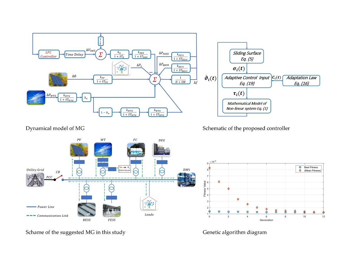
Then the error paths reach the convergence region σ ( t ) < ϱ in finite time. The block diagram of the ACBF-TSMC system is represented in Figure 1.
Proof. 
To prove the control law Eq. (19), the candidate Lyapunov function is considered as
L = 1 2 σ ( t ) 2 + C ^ P S D t C ^ P S D ( 0 ) 2 .
By taking the derivative of the Eq. (20), yields:
L ˙ = σ t σ ˙ t + C ^ P S D t C ^ P S D ( 0 ) C ^ ˙ P S D t .
By replacing σ ˙ t and C ^ P S D 0 = 0 in Eq. (21), yields:
L ˙ = σ t A H 11 H 12 B 1 A ϑ 1 + B H 21 H 22 B 1 A ϑ 1 + G 2 τ + 1 M A D + C ^ P S D t C ^ ˙ P S D t .
Then, by replacing the control signal of Eq. (19) in Eq. (22), yields:
L ˙ = σ t C ^ P S D t   s g n   σ t + 1 M A D + C ^ P S D t C ^ ˙ P S D t σ t × 1 M A D t C ^ P S D t + C ^ P S D t C ^ ˙ P S D t σ t × 1 M A D t C ^ P S D t + C ^ P S D t × ϱ ϱ σ t 2 s g n σ t σ ˙ t ϱ ϱ σ t 2 1 M A D t C ^ P S D t s g n   σ t × s g n   σ t .
Eq. (23) can be rewritten as
L ˙ C ^ P S D t 1 M A D t σ t C ^ P S D t × ϱ ϱ σ t 2 C ^ P S D t 1 M A D t ,
so that since C ^ P S D t 1 M A D t and ϱ ϱ σ t 2 > 0 , one finds
L ˙ 2 C ^ P S D t 1 M A D t σ t 2 2 ϱ ϱ σ t 2 C ^ P S D t 1 M A D t C ^ P S D t 2 ɸ σ t 2 + C ^ P S D t 2 , ɸ L ( t ) 0.5
so that ɸ = 2 C ^ P S D t 1 M A D t min 1 , 2 ϱ ϱ σ t 2 . ☐
Based on the proofs, it can be seen that the state trajectories of system Eq. (2) converge to the origin in a finite time by the proposed controller.
Ultimately, the genetic algorithm is used to optimize the parameters of the proposed controller. Considering that there are several constants in the proposed controller, the appropriate selection of these constants can directly affect the performance and optimality of the proposed controller significantly. For higher performance and accuracy, the following genetic algorithm fitness function is used to tune the controller gains and parameters.
ζ = 0 t ω 1 ϑ 1 2 + ω 2 ϑ 2 2 + + ω i ϑ i 2 d t
where ω i is the weighting factor and ϑ introduces the state of the system from Eq. (1)The goal of optimization is to minimize the fitness function of Eq. (26), thereby minimizing the stability error of the controlled system.

4. Simulation results

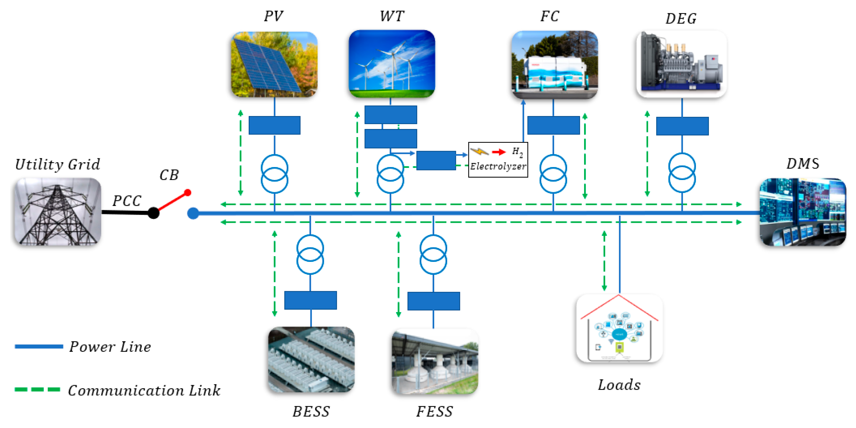
In this section, for further validation, the proposed control method has been implemented on the mathematical model of the nonlinear systems of Eq. (2) and the simulation results have been analyzed in the MATLAB- Simulink environment. For this purpose, it is necessary to examine a specific case of the microgrid system as an example. The scheme of the desired autonomous Micro-Grid (MG) in this example is demonstrated in Figure 2.
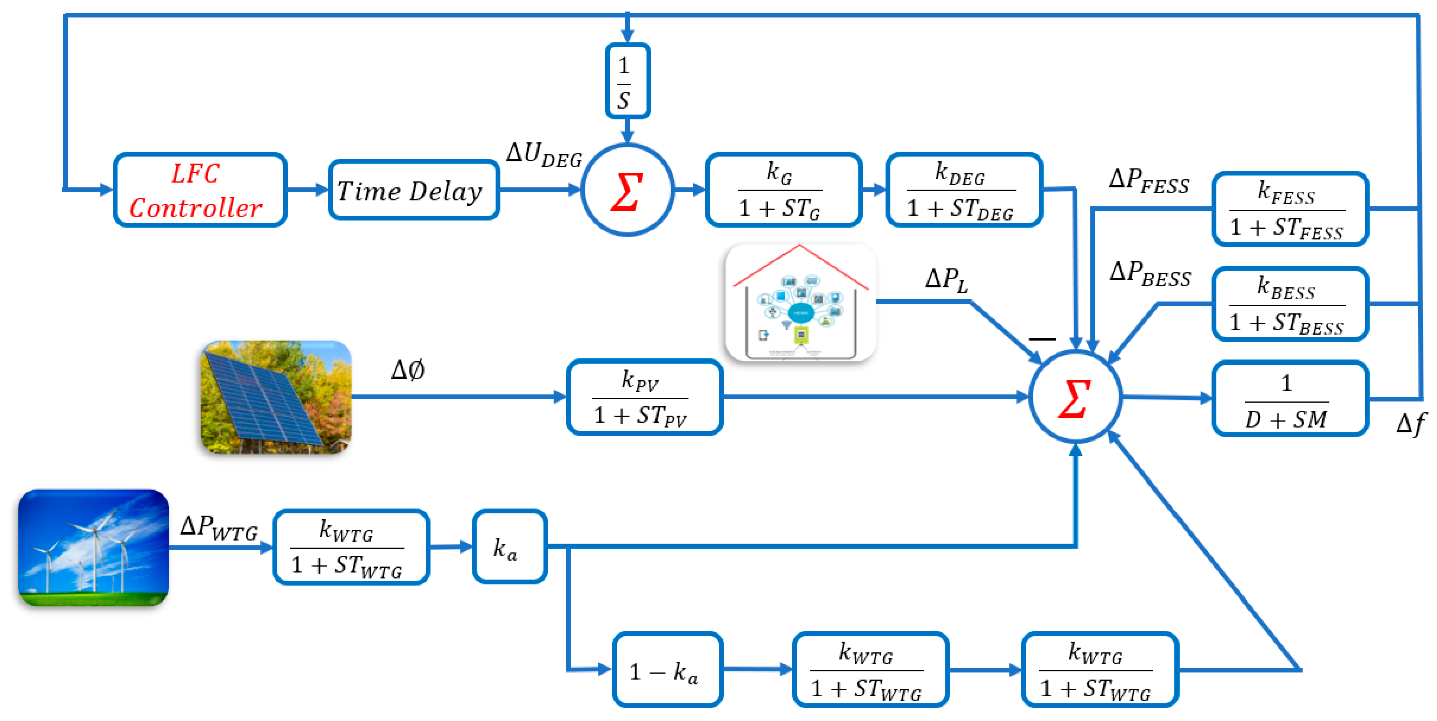
Based on Figure 2, it can be seen that the proposed MG consists of a bus-bar, Wind Turbine (WT), Fuel Cell (FC), Photovoltaic Units (PV), Diesel Engine Generator (DEG), Flywheel Energy Storage System (FESS), Battery Energy Storage System (BESS), and electric Loads [18,50,51]. In addition, network management is done by a distribution management system (DMS). In order to control the proposed system, bi-directional data can be transmitted using communication links between sources [52] and DMS. Figure 3 indicates the small signal model of the desired islanded MG. According to Figure 3, WT, FC, PV, FESS, and BESS resources are connected to the AC MG using AC/DC/AC and DC/AC interfacing inverters. A circuit breaker is used for all supplies to protect the MGs. In order to create a rotating chain for controlling the secondary frequency, a diesel engine generator is used.
The MG parameters demonstrated in Figure 2 and Figure 3 are presented in Table 1 [53]. MG load changes as well as changes in the output of power-generating sources lead to MG frequency fluctuations. Power sources in MG are divided into controllable (DEG, BEES, and FESS) and non-controllable (WT, PV, and FC) categories. In addition, power changes of uncontrollable sources are defined as predictable disturbances and load changes are defined as unpredictable disturbances:
ϑ ˙ = H ϑ + G τ + J D ,
where ϑ ˙ = ϑ 1 T ϑ 1 T T , ϑ 1 = f R , ϑ 2 = P d e g P b e s s P f e s s T R 3 represent the states of system, τ t = τ d e g τ b e s s τ f e s s T R 3 represent the control signals, D = P f c P l + P w t g + P p v R represents the external disturbance, J = 1 M 0 0 0 T , H = H 11 H 12 H 21 H 22 , and G = 0 G 2 represent matrices of appropriate dimensions, where H 11 = J M , H 12 = 1 M 1 1 1 , H 21 = K d e g R T d e g 0 0 T , H 22 = d i a g 1 T d e g , 1 T b e s s , 1 T f e s s , and G 2 = d i a g K d e g T d e g , K b e s s T b e s s , K f e s s T f e s s R 3 × 3 are nonsingular matrices. In the result, the dynamical model Eq. (27) can be rewritten as
ϑ ˙ 1 = H 11 ϑ 1 + H 12 ϑ 2 + 1 M D , ϑ ˙ 2 = H 21 ϑ 1 + H 22 ϑ 2 + G 2 τ ,
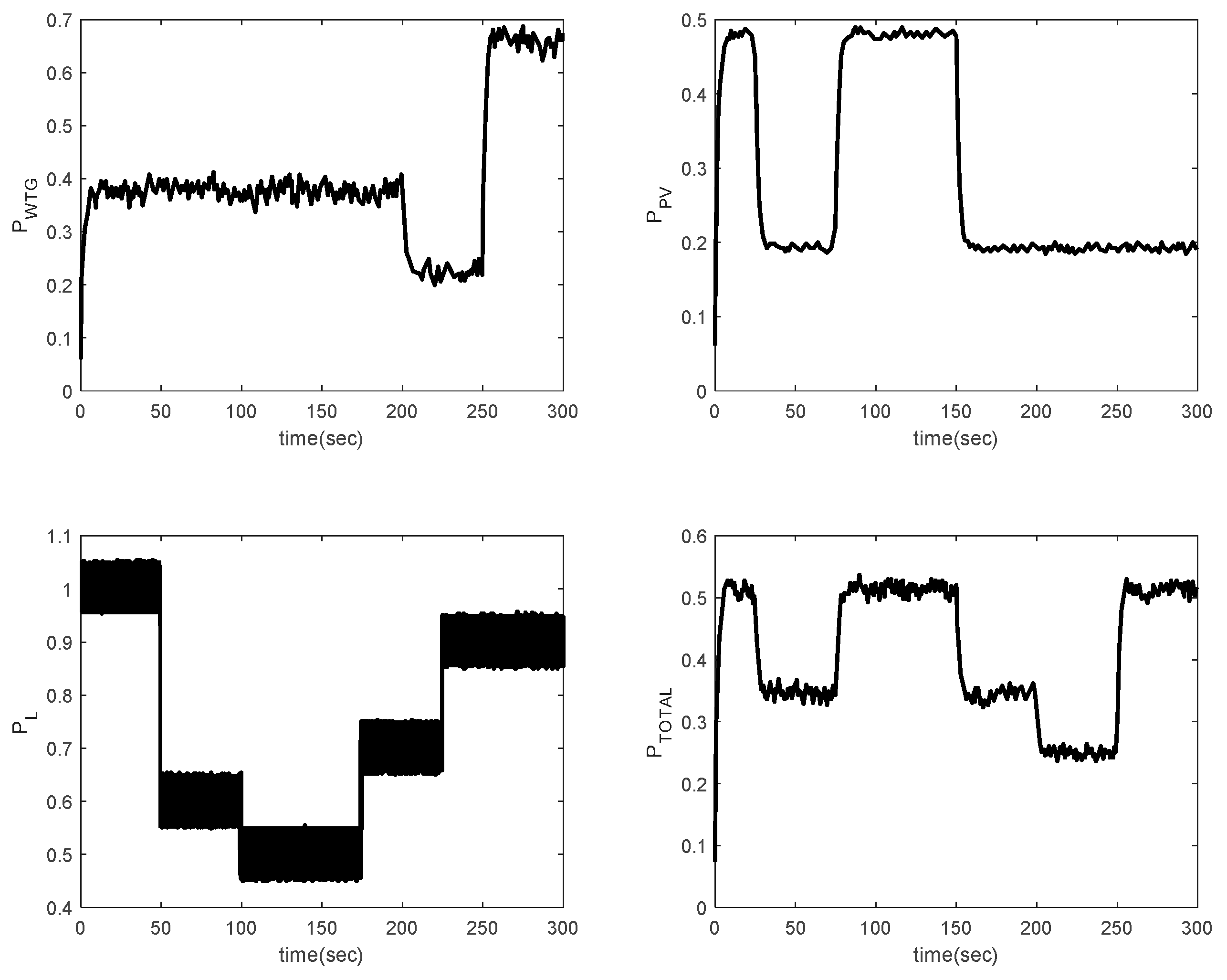
Furthermore, disturbances applied to the system, sudden changes in load, and electricity production from renewable sources are conforming to Figure 4 in [54]. According to Figure 4, it can be seen that load disturbances and renewable energies are very high. This system is simulated for 300 seconds. Moreover, Table 1 shows the values of system parameters.
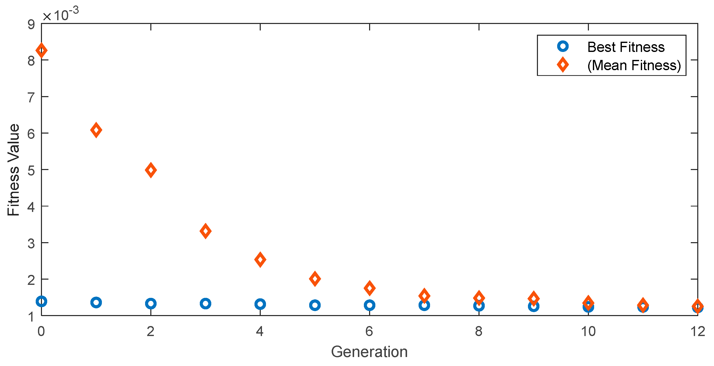
The optimization of the genetic algorithm implemented with the fitness function of Eq. (26) is shown in Figure 5, which shows that the best value of the fitness function is from 0.001256 to 0.001226, and the average value converges to the best value in twelve generations. Finally, the resulting parameters of the proposed controller are indicated in Table 2.
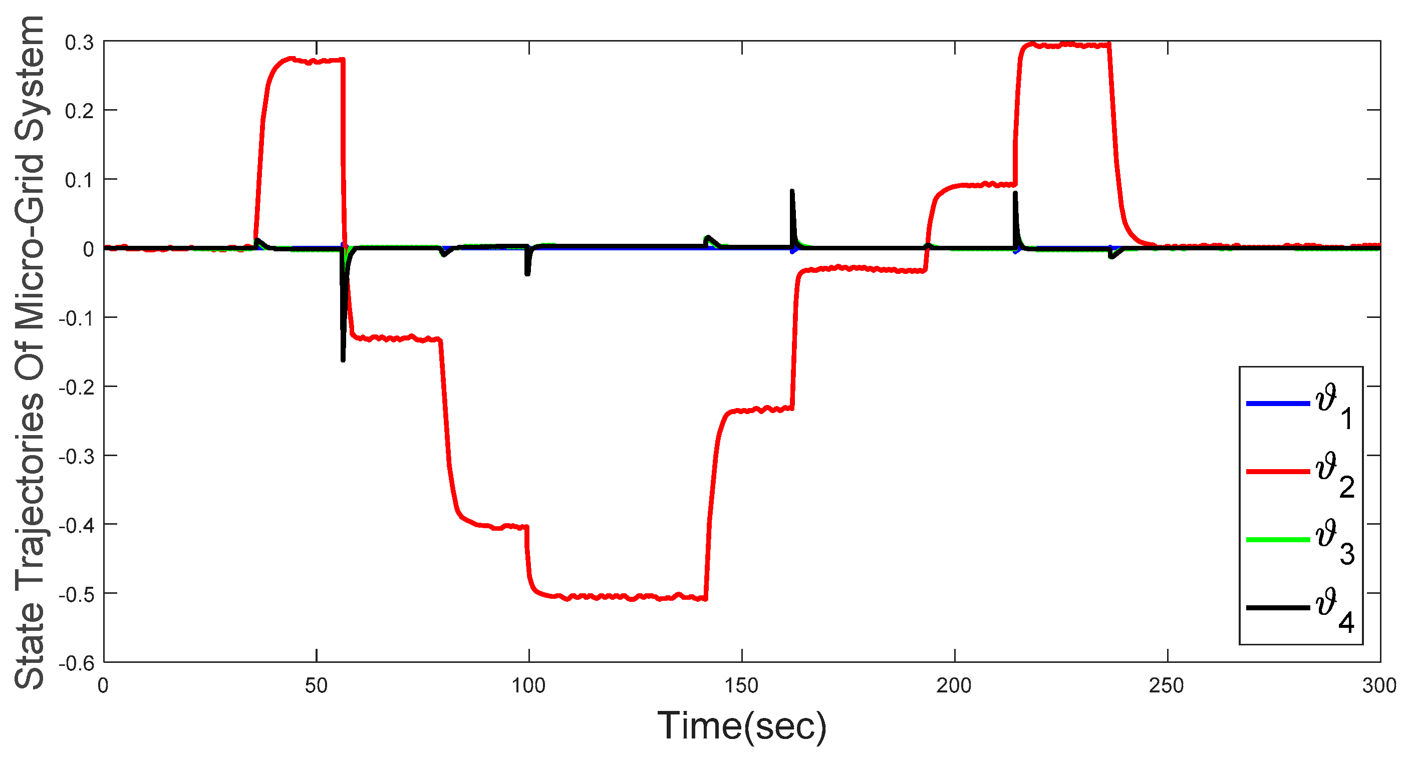
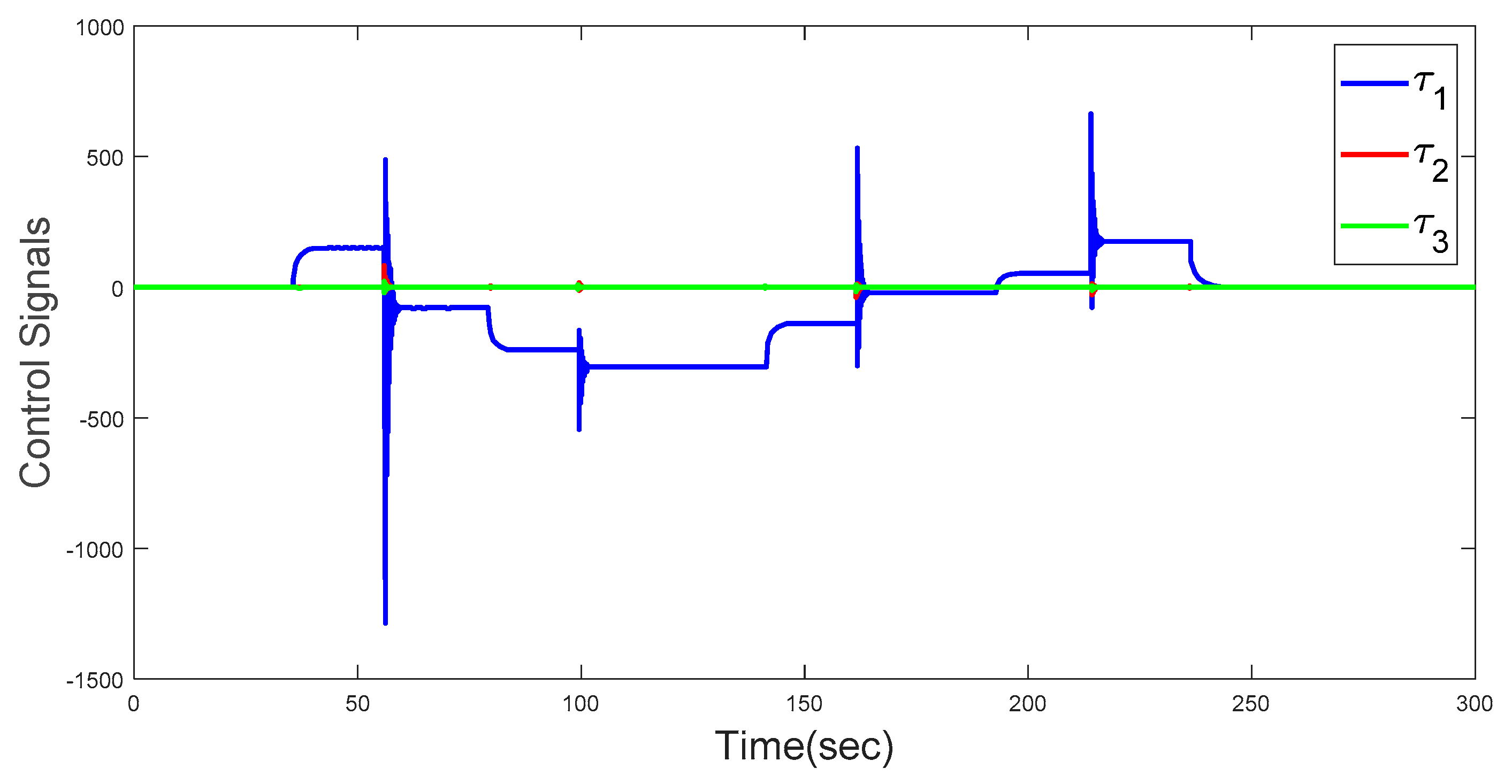
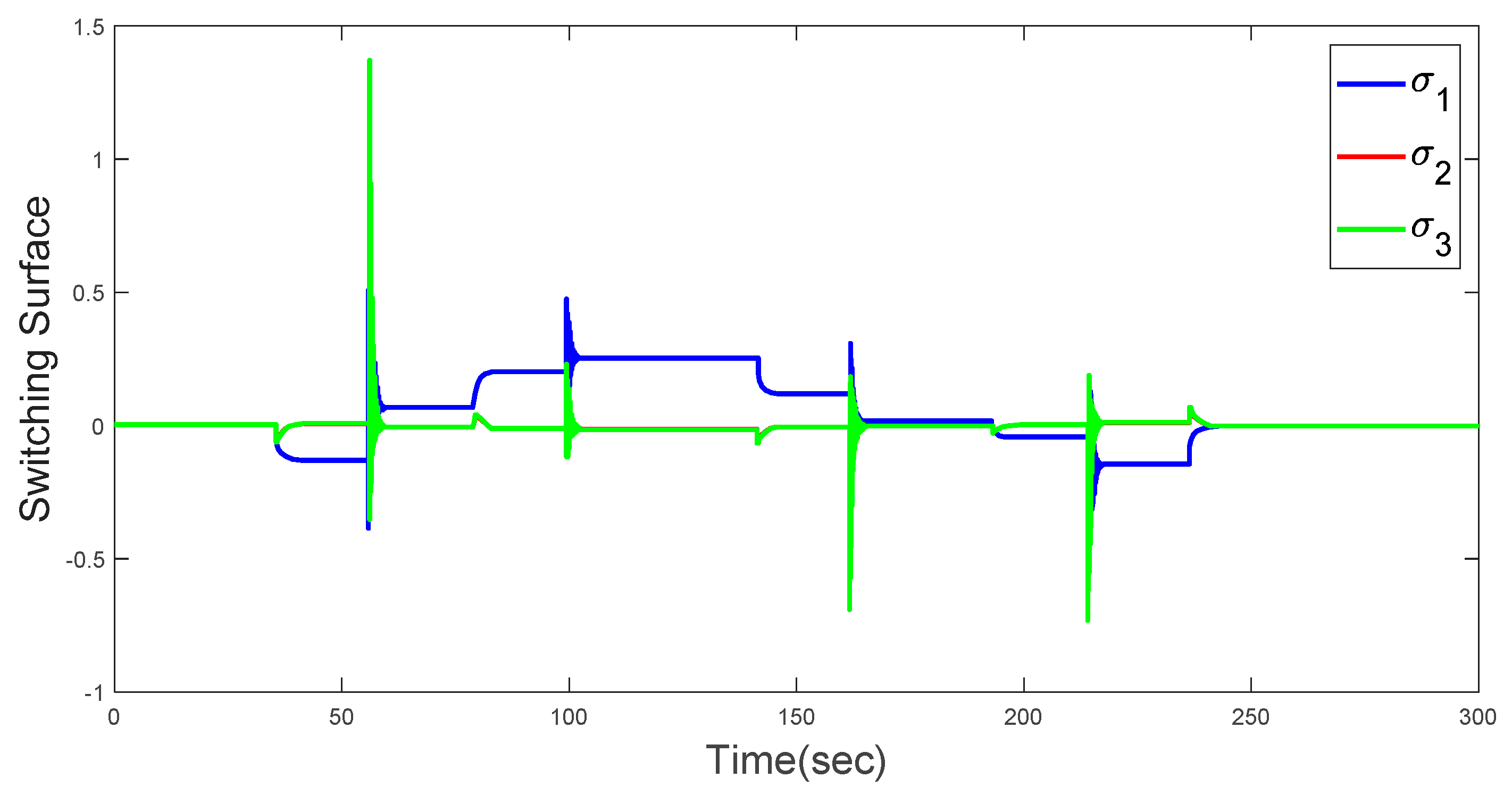
Based on the results obtained from the simulation of the proposed control system in the MATLAB- Simulink environment, Figure 6 shows the status trajectories of the MG system, which demonstrates that the proposed control system was able to stabilize the system in a certain range in the presence of large changes in load and power generation. Figure 7 shows the control signals, which can be clearly seen that the suggested controller, with the help of the ACBF, has been able to reduce the undesirable phenomenon of chattering well and adapt the control system to load changes and scattered generations. In addition, Figure 8 demonstrates the switching surfaces, which can be seen that the presented switching surfaces have also reduced chattering well.
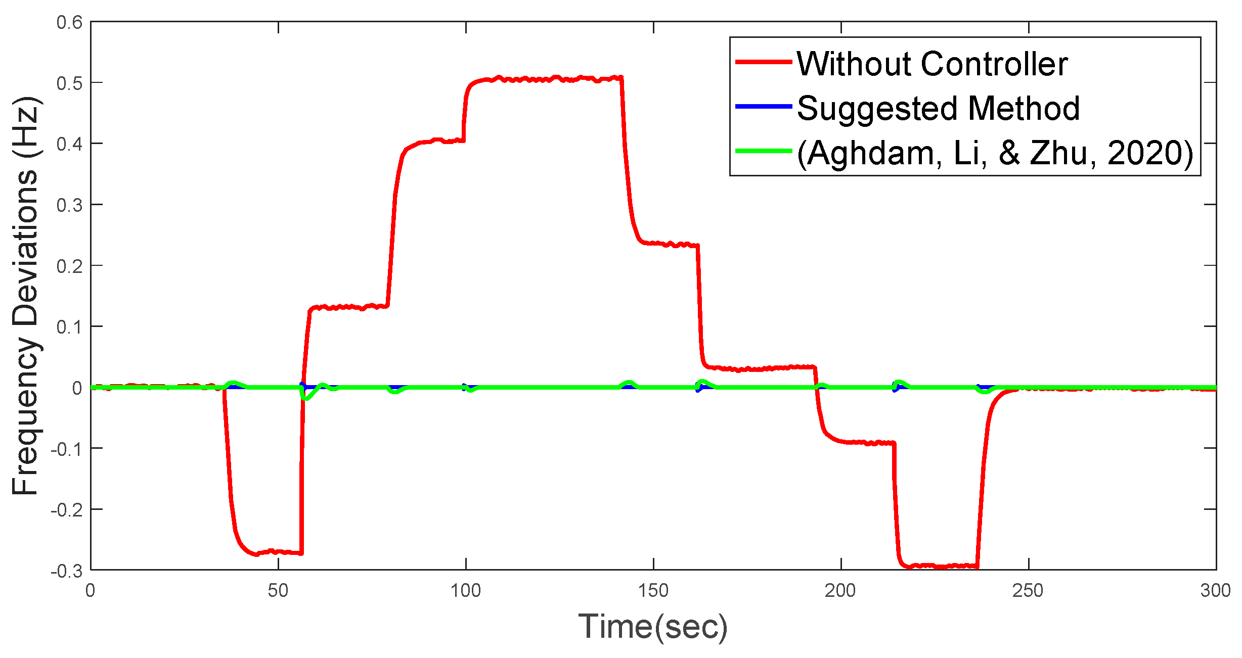
In addition, to demonstrate the performance of the suggested control technique in stabilizing the frequency of the MG system, the suggested control technique is compared with the control method in [55]. According to the Figure 9, it can be seen that the suggested finite time controller operates with less fluctuation and less overshoot and undershoot than controller [55] and was able to stabilize the system frequency well.
Based on the simulations, it can be seen that the proposed controller has a good performance in the presence of scattered energy production and large load changes and has been able to guarantee the stability of nonlinear system Eq. (2). To sum up, the proposed control method has been very effective for nonlinear systems and can be practical and optimal in practical nonlinear systems.

5. Conclusion

In conclusion, the proposed OACBF-TSMC approach has demonstrated its effectiveness and efficiency in stabilizing mathematical model of nonlinear systems in the presence of model uncertainties and external disturbances. The simulation results indicate that the approach provides significant robustness against model uncertainties and external disturbances and converges the state trajectories of the nonlinear system in a finite time to a pre-defined point at the origin. In addition, it was observed that by using the adaptive barrier function, the chattering problem in the control inputs was completely eliminated. These promising results highlight the potential of the OACBF-TSMC approach for real-world applications to enhance the performance and stability of the system. However, further research is necessary to investigate the scalability and robustness of this approach for large-scale systems with multiple sources and loads. Overall, the proposed approach provides a viable solution to the challenges associated with stabilizing disturbed nonlinear systems.

Author Contributions

Conceptualization, S.M., M.A.S., M.H.A. and F.F.S.; formal analysis, S.M. S.Z.A., and F.F.S; funding acquisition, A.S.A., F.F.S.; investigation, S.M., M.H.A. and F.F.S.; methodology, F.F.S., A.S.A., M.A.S., and S.M.; writing—original draft, S.Z.A., M.A.S., M.H.A.; writing—review and editing, and supervision, M.A.S., S.Z.A., S.M, F.F.S. All authors have read and agreed to the published version of the manuscript.

Funding

The authors extend their application to the Deputyship for Research & Innovation, Ministry of Education in Saudi Arabia for funding this research work through the Project number (IF2/PSAU/2022/01/23085).

Institutional Review Board Statement

Not applicable.

Informed Consent Statement

Not applicable.

Data Availability Statement

The data that support the findings of this study are available within the article.

Conflicts of Interest

The authors declare no conflict of interest.

Nomenclature

W T Wind Turbine ϑ States of the system
F C Fuel Cell τ t Control signals
P V Photovoltaic Units D External disturbances
D E G Diesel Engine Generator C 1 Upper bound of D
F E S S Flywheel Energy Storage System A Constant for switching manifold
B E S S Battery Energy Storage System B Constant for switching manifold
M G Micro-Grid C ^ ( t ) Estimation of C 1
σ ( t ) Switching Manifold ρ Constant for adaptation law
α Scaler parameter b Positive odd integer
t s Settling time L The candidate Lyapunov’s function
t 0 Initial time ϱ Constant for barrier function

References

  1. Isidori, A. Nonlinear control systems II; Springer: 2013.
  2. Mohler, R.R. Nonlinear systems (vol. 2) applications to bilinear control; Prentice-Hall, Inc.: 1991.
  3. Sepestanaki, M.A.; Barhaghtalab, M.H.; Mobayen, S.; Jalilvand, A.; Fekih, A.; Skruch, P. Chattering-Free Terminal Sliding Mode Control Based on Adaptive Barrier Function for Chaotic Systems With Unknown Uncertainties. IEEE Access 2022, 10, 103469–103484. [Google Scholar] [CrossRef]
  4. Liang, Y.-W.; Liaw, D.-C.; Lee, T.-C. Reliable control of nonlinear systems. IEEE Transactions on Automatic Control 2000, 45, 706–710. [Google Scholar] [CrossRef]
  5. Baldi, S.; Michailidis, I.; Kosmatopoulos, E.B.; Papachristodoulou, A.; Ioannou, P.A. Convex Design Control for Practical Nonlinear Systems. IEEE Trans. Autom. Control. 2014, 59, 1692–1705. [Google Scholar] [CrossRef]
  6. Zhang, H.; Zhao, X.; Wang, H.; Zong, G.; Xu, N. Hierarchical Sliding-Mode Surface-Based Adaptive Actor–Critic Optimal Control for Switched Nonlinear Systems With Unknown Perturbation. IEEE Trans. Neural Networks Learn. Syst. 2022, 1–13. [Google Scholar] [CrossRef]
  7. Ahmed, N.M.; Ebeed, M.; Alhejji, A.; Refai, A. A Robust Cascaded Controller for Load Frequency Control in Renewable Energy Integrated Microgrid Containing PEV. Int. J. Renew. Energy Res. 2023, 13, 423–433. [Google Scholar] [CrossRef]
  8. Khooban, M.H.; Niknam, T.; Blaabjerg, F.; Dragičević, T. A new load frequency control strategy for micro-grids with considering electrical vehicles. Electr. Power Syst. Res. 2017, 143, 585–598. [Google Scholar] [CrossRef]
  9. Lorenzetti, P.; Weiss, G. Saturating PI Control of Stable Nonlinear Systems Using Singular Perturbations. IEEE Trans. Autom. Control. 2022, 68, 867–882. [Google Scholar] [CrossRef]
  10. Zhao, C.; Guo, L. Towards a theoretical foundation of PID control for uncertain nonlinear systems. Automatica 2022, 142, 110360. [Google Scholar] [CrossRef]
  11. Rerkpreedapong, D.; Hasanovic, A.; Feliachi, A. Robust load frequency control using genetic algorithms and linear matrix inequalities. IEEE Trans. Power Syst. 2003, 18, 855–861. [Google Scholar] [CrossRef]
  12. Giaccagli, M.; Andrieu, V.; Tarbouriech, S.; Astolfi, D. LMI conditions for contraction, integral action, and output feedback stabilization for a class of nonlinear systems. Automatica 2023, 154. [Google Scholar] [CrossRef]
  13. Al Sumarmad, K.A.; Sulaiman, N.; Wahab, N.I.A.; Hizam, H. Energy Management and Voltage Control in Microgrids Using Artificial Neural Networks, PID, and Fuzzy Logic Controllers. Energies 2022, 15, 303. [Google Scholar] [CrossRef]
  14. Bhosale, R.T.; Agarwal, V. Fuzzy logic control of the ultracapacitor interface for enhanced transient response and voltage stability of a DC microgrid. IEEE Transactions on Industry Applications 2018, 55, 712–720. [Google Scholar] [CrossRef]
  15. Son, S.H.; Choi, H.-K.; Moon, J.; Kwon, J.S.-I. Hybrid Koopman model predictive control of nonlinear systems using multiple EDMD models: An application to a batch pulp digester with feed fluctuation. Control. Eng. Pr. 2021, 118, 104956. [Google Scholar] [CrossRef]
  16. Narasingam, A.; Son, S.H.; Kwon, J.S.-I. Data-driven feedback stabilisation of nonlinear systems: Koopman-based model predictive control. Int. J. Control. 2022, 96, 770–781. [Google Scholar] [CrossRef]
  17. Morstyn, T.; Savkin, A.V.; Hredzak, B.; Agelidis, V.G. Multi-Agent Sliding Mode Control for State of Charge Balancing Between Battery Energy Storage Systems Distributed in a DC Microgrid. IEEE Trans. Smart Grid 2017, 9, 4735–4743. [Google Scholar] [CrossRef]
  18. Bagheri, A.; Jabbari, A.; Mobayen, S. An intelligent ABC-based terminal sliding mode controller for load-frequency control of islanded micro-grids. Sustain. Cities Soc. 2020, 64, 102544. [Google Scholar] [CrossRef]
  19. Mu, C.; Tang, Y.; He, H. Observer-based sliding mode frequency control for micro-grid with photovoltaic energy integration. In Proceedings of the 2016 IEEE Power and Energy Society General Meeting (PESGM); 2016; pp. 1–5. [Google Scholar]
  20. Alnuman, H.; Hsia, K.-H.; Sepestanaki, M.A.; Ahmed, E.M.; Mobayen, S.; Armghan, A. Design of Continuous Finite-Time Controller Based on Adaptive Tuning Approach for Disturbed Boost Converters. Mathematics 2023, 11, 1757. [Google Scholar] [CrossRef]
  21. Rouhani, S.H.; Abbaszadeh, E.; Sepestanaki, M.A.; Mobayen, S.; Su, C.-L.; Nemati, A. Adaptive Finite-Time Tracking Control of Fractional Microgrids Against Time-Delay Attacks. IEEE Trans. Ind. Appl. 2023, 1–13. [Google Scholar] [CrossRef]
  22. El Makrini, I.; Guerrero, C.R.; Lefeber, D.; Vanderborght, B. The Variable Boundary Layer Sliding Mode Control: A Safe and Performant Control for Compliant Joint Manipulators. IEEE Robot. Autom. Lett. 2016, 2, 187–192. [Google Scholar] [CrossRef]
  23. Hou, S.; Wang, C.; Chu, Y.; Fei, J. Neural-Observer-Based Terminal Sliding Mode Control: Design and Application. IEEE Trans. Fuzzy Syst. 2022, 30, 4800–4814. [Google Scholar] [CrossRef]
  24. Elmorshedy, M.F.; Selvam, S.; Mahajan, S.B.; Almakhles, D. Investigation of high-gain two-tier converter with PI and super-twisting sliding mode control. ISA Trans. 2023, 138, 628–638. [Google Scholar] [CrossRef]
  25. Liu, J.; Shen, X.; Alcaide, A.M.; Yin, Y.; Leon, J.I.; Vazquez, S.; Wu, L.; Franquelo, L.G. Sliding Mode Control of Grid-Connected Neutral-Point-Clamped Converters Via High-Gain Observer. IEEE Trans. Ind. Electron. 2021, 69, 4010–4021. [Google Scholar] [CrossRef]
  26. Hamayun, M.T.; Edwards, C.; Alwi, H.; Hamayun, M.T.; Edwards, C.; Alwi, H. Integral Sliding Mode Control; Springer: 2016.
  27. Yao, Q.; Jahanshahi, H.; Moroz, I.; Bekiros, S.; Alassafi, M.O. Indirect neural-based finite-time integral sliding mode control for trajectory tracking guidance of Mars entry vehicle. Adv. Space Res. 2022, 71, 3723–3733. [Google Scholar] [CrossRef]
  28. Feng, H.; Song, Q.; Ma, S.; Ma, W.; Yin, C.; Cao, D.; Yu, H. A new adaptive sliding mode controller based on the RBF neural network for an electro-hydraulic servo system. ISA Trans. 2022, 129, 472–484. [Google Scholar] [CrossRef] [PubMed]
  29. Li, R.; Yang, L.; Chen, Y.; Lai, G. Adaptive Sliding Mode Control of Robot Manipulators with System Failures. Mathematics 2022, 10, 339. [Google Scholar] [CrossRef]
  30. Qureshi, M.S.; Singh, P.; Swarnkar, P. Intelligent fuzzy logic-based sliding mode control methodologies for pick and drop operation of robotic manipulator. International Journal of Computational Vision and Robotics 2022, 12, 549–571. [Google Scholar] [CrossRef]
  31. Sepestanaki, M.A.; Bahmani, H.; Ali, M.A.; Jalilvand, A.; Mobayen, S.; Fekih, A. Fuzzy Estimator Indirect Terminal Sliding Mode Control of Nonlinear Systems Based on Adaptive Continuous Barrier Function. IEEE Access 2022, 10, 34296–34305. [Google Scholar] [CrossRef]
  32. Hao, X.; Salhi, I.; Laghrouche, S.; Ait-Amirat, Y.; Djerdir, A. Nonlinear Disturbance Observer-based sliding mode control of interleaved boost converter for fuel cell used in microgrids. IFAC-PapersOnLine 2022, 55, 665–670. [Google Scholar] [CrossRef]
  33. Gao, S.; Ning, B.; Dong, H. Adaptive neural control with intercepted adaptation for time-delay saturated nonlinear systems. Neural Comput. Appl. 2015, 26, 1849–1857. [Google Scholar] [CrossRef]
  34. Rabah, K.; Ladaci, S. A Fractional Adaptive Sliding Mode Control Configuration for Synchronizing Disturbed Fractional-Order Chaotic Systems. Circuits, Syst. Signal Process. 2019, 39, 1244–1264. [Google Scholar] [CrossRef]
  35. Yan, M.; Song, J.; Zuo, L.; Yang, P. Neural Adaptive Sliding-Mode Control of a Vehicle Platoon Using Output Feedback. Energies 2017, 10, 1906. [Google Scholar] [CrossRef]
  36. Swaroop, D.; Hedrick, J.; Yip, P.; Gerdes, J. Dynamic surface control for a class of nonlinear systems. IEEE Trans. Autom. Control. 2000, 45, 1893–1899. [Google Scholar] [CrossRef]
  37. Dou, Z.; Tang, L.; Sun, Y.; Zhang, C.; Yang, W.; Xu, D. Prescribed Performance-Based Adaptive Terminal Sliding Mode Control for Virtual Synchronous Generators. Math. Probl. Eng. 2022, 2022, 1–10. [Google Scholar] [CrossRef]
  38. Yu, X.; Feng, Y.; Man, Z. Terminal sliding mode control–an overview. IEEE Open Journal of the Industrial Electronics Society 2020, 2, 36–52. [Google Scholar] [CrossRef]
  39. Elyaalaoui, K.; Labbadi, M.; Ouassaid, M.; Cherkaoui, M.; Bouzi, M. High-order sliding-mode control using integral terminal sliding manifold for a wind turbine under grid faults. Int. J. Control. 2023, 1–16. [Google Scholar] [CrossRef]
  40. Dong, H.; Yang, X.; Gao, H.; Yu, X. Practical Terminal Sliding-Mode Control and Its Applications in Servo Systems. IEEE Trans. Ind. Electron. 2022, 70, 752–761. [Google Scholar] [CrossRef]
  41. Mu, C.; He, H. Dynamic Behavior of Terminal Sliding Mode Control. IEEE Trans. Ind. Electron. 2017, 65, 3480–3490. [Google Scholar] [CrossRef]
  42. Zhihong, M.; Paplinski, A.; Wu, H. A robust MIMO terminal sliding mode control scheme for rigid robotic manipulators. IEEE Trans. Autom. Control. 1994, 39, 2464–2469. [Google Scholar] [CrossRef]
  43. Kamal, S.; Moreno, J.A.; Chalanga, A.; Bandyopadhyay, B.; Fridman, L.M. Continuous terminal sliding-mode controller. Automatica 2016, 69, 308–314. [Google Scholar] [CrossRef]
  44. Sepestanaki, M.A.; Jalilvand, A.; Mobayen, S.; Zhang, C. Design of adaptive continuous barrier function finite time stabilizer for TLP systems in floating offshore wind turbines. Ocean Eng. 2022, 262. [Google Scholar] [CrossRef]
  45. Nekoukar, V.; Erfanian, A. A Decentralized Modular Control Framework for Robust Control of FES-Activated Walker-Assisted Paraplegic Walking Using Terminal Sliding Mode and Fuzzy Logic Control. IEEE Trans. Biomed. Eng. 2012, 59, 2818–2827. [Google Scholar] [CrossRef] [PubMed]
  46. Obeid, H.; Fridman, L.M.; Laghrouche, S.; Harmouche, M. Barrier function-based adaptive sliding mode control. Automatica 2018, 93, 540–544. [Google Scholar] [CrossRef]
  47. Plestan, F.; Shtessel, Y.; Brégeault, V.; Poznyak, A. New methodologies for adaptive sliding mode control. Int. J. Control 2010, 83, 1907–1919. [Google Scholar] [CrossRef]
  48. Thompson, D.E. Design analysis: mathematical modeling of nonlinear systems; Cambridge University Press: 1999.
  49. Xiu, C.; Guo, P. Global Terminal Sliding Mode Control With the Quick Reaching Law and Its Application. IEEE Access 2018, 6, 49793–49800. [Google Scholar] [CrossRef]
  50. Khalil, A.; Rajab, Z.; Alfergani, A.; Mohamed, O. The impact of the time delay on the load frequency control system in microgrid with plug-in-electric vehicles. Sustain. Cities Soc. 2017, 35, 365–377. [Google Scholar] [CrossRef]
  51. Abazari, A.; Monsef, H.; Wu, B. Coordination strategies of distributed energy resources including FESS, DEG, FC and WTG in load frequency control (LFC) scheme of hybrid isolated micro-grid. Int. J. Electr. Power Energy Syst. 2019, 109, 535–547. [Google Scholar] [CrossRef]
  52. Khooban, M.-H.; Niknam, T.; Blaabjerg, F.; Davari, P.; Dragicevic, T. A robust adaptive load frequency control for micro-grids. ISA Trans. 2016, 65, 220–229. [Google Scholar] [CrossRef]
  53. Khooban, M.-H. Secondary Load Frequency Control of Time-Delay Stand-Alone Microgrids With Electric Vehicles. IEEE Trans. Ind. Electron. 2017, 65, 7416–7422. [Google Scholar] [CrossRef]
  54. Pan, I.; Das, S. Fractional Order AGC for Distributed Energy Resources Using Robust Optimization. IEEE Trans. Smart Grid 2015, 7, 2175–2186. [Google Scholar] [CrossRef]
  55. Aghdam, M.M.; Li, L.; Zhu, J. Comprehensive study of finite control set model predictive control algorithms for power converter control in microgrids. IET Smart Grid 2020, 3, 1–10. [Google Scholar] [CrossRef]
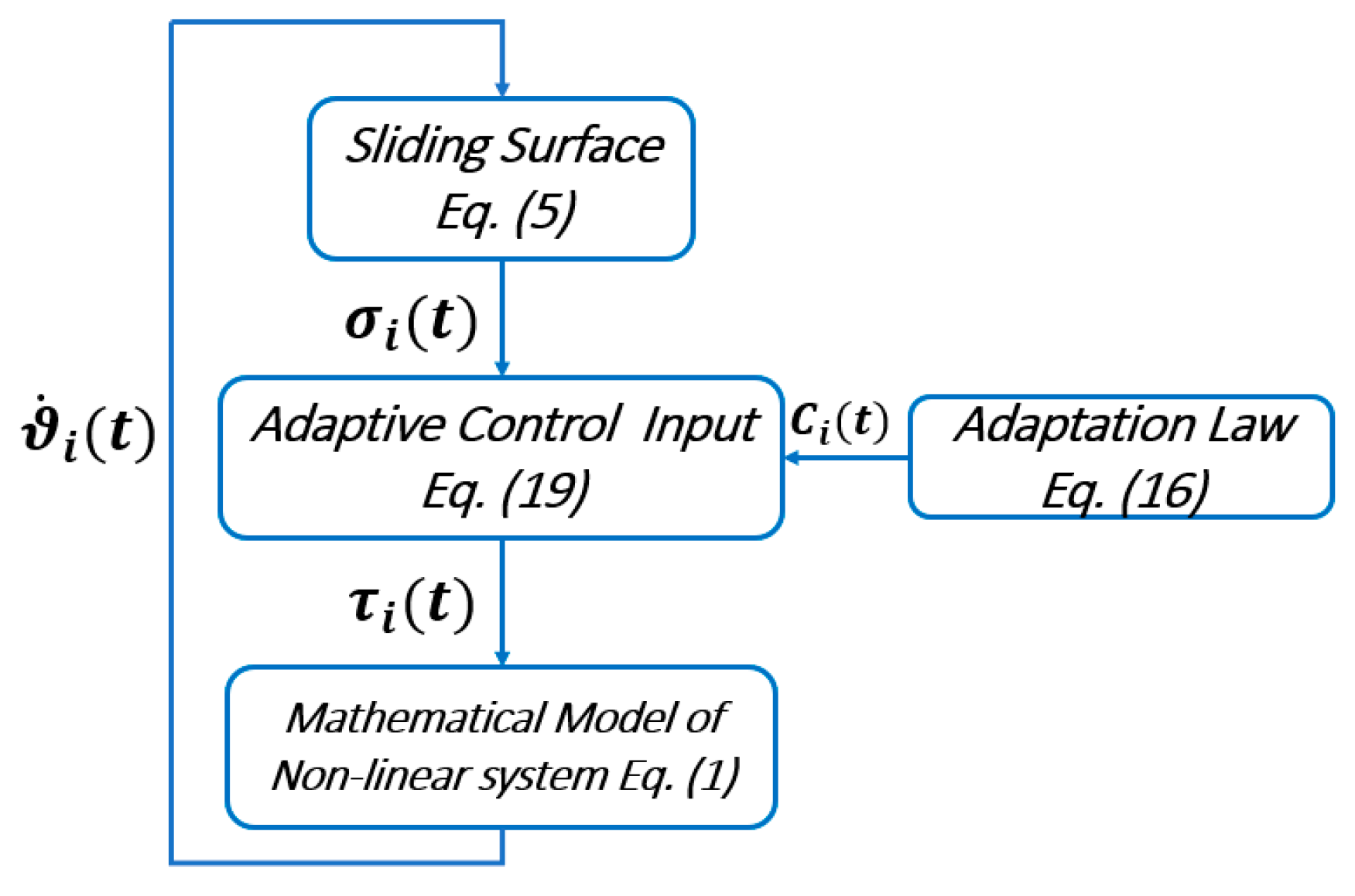
Figure 1. Schematic of the proposed controller.
Preprints 86715 g001
Figure 2. Schame of the suggested MG in this study.
Preprints 86715 g002
Figure 3. Dynamical model of MG.
Preprints 86715 g003
Figure 4. The renewable generations and demand powers which are autonomous of the controller structure.
Preprints 86715 g004
Figure 5. Genetic algorithm diagram.
Preprints 86715 g005
Figure 6. State trajectories of MG system.
Preprints 86715 g006
Figure 7. Control signals.
Preprints 86715 g007
Figure 8. Swtiching surface.
Preprints 86715 g008
Figure 9. Comparison of the suggested method with the controller in [55] in order to stabilize the frequency load.
Preprints 86715 g009
Table 1. Parameter of MG system.
Parameters Values Parameters Values
T g   ( Converter time constant ) 2 T f e s s 0.1
T d e g  (Diesel generator time constant) 1 T b e s s 0.1
T w t g 2 K d e g 1/300
T p v 1.8 K w t g 1
T a e  (The time constant of the aqua electrolyzer) 0.5 K p v 1
T f c 4 K a e 1/500
R  (DG speed regulation) 3 K f c 1/100
J  (Damping coefficient) 0.012 K f e s s -1/100
M  (Inertia constant) 0.2 K b e s s -1/300
Table 2. Control gains of the proposed controller.
Symbol Title Values
A Constants of Eq. (5) 62.316 62.316 62.423
B Constants of Eq. (5) D i a g 0.6512 0.6512 0.6212
ρ 2 1/300
ϱ 1.8 1
Disclaimer/Publisher’s Note: The statements, opinions and data contained in all publications are solely those of the individual author(s) and contributor(s) and not of MDPI and/or the editor(s). MDPI and/or the editor(s) disclaim responsibility for any injury to people or property resulting from any ideas, methods, instructions or products referred to in the content.
Copyright: This open access article is published under a Creative Commons CC BY 4.0 license, which permit the free download, distribution, and reuse, provided that the author and preprint are cited in any reuse.
Prerpints.org logo

Preprints.org is a free preprint server supported by MDPI in Basel, Switzerland.

Subscribe

© 2024 MDPI (Basel, Switzerland) unless otherwise stated