Submitted:
03 October 2023
Posted:
04 October 2023
You are already at the latest version
Abstract
Keywords:
1. Introduction
2. Method for assessment of theoretical safety against freight wagon derailment
- Yja – the total reaction of the rail in contact with the attacking (outer) wheel. The parameter is involved in equations (1) and (2);
- Yji – horizontal load force between the inner (non-attacking) wheel of the examined track axle and the inner rail. The parameter is involved in equation (2);
- Qjk,min – the lowest value of the vertical reaction of the wheel calculated when the frame of the wagon is twisted. The parameter is involved in Equation (1).
2.1. Methodology for theoretical determination of leading forces Ya on axles of railway vehicles with bogies
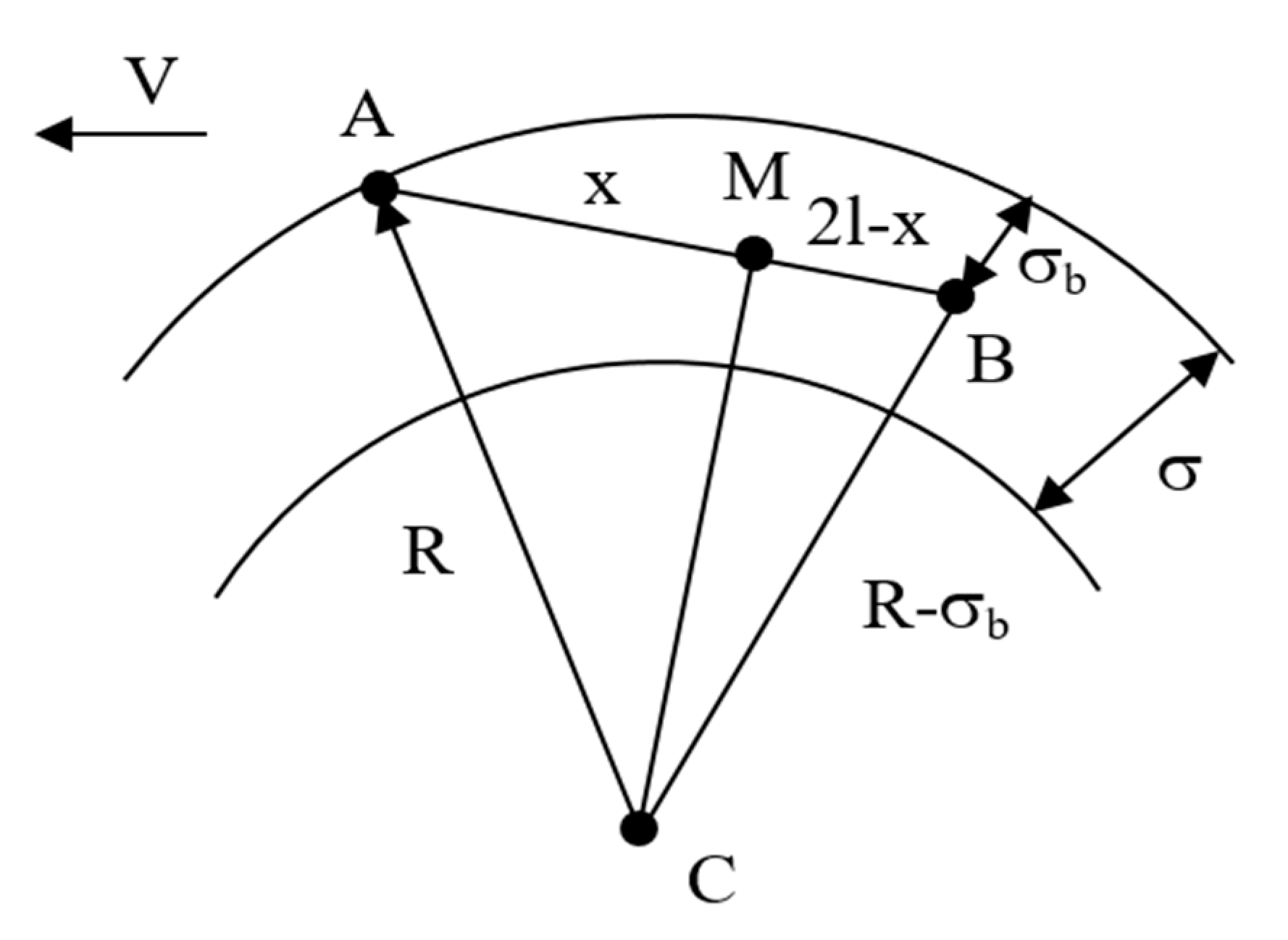
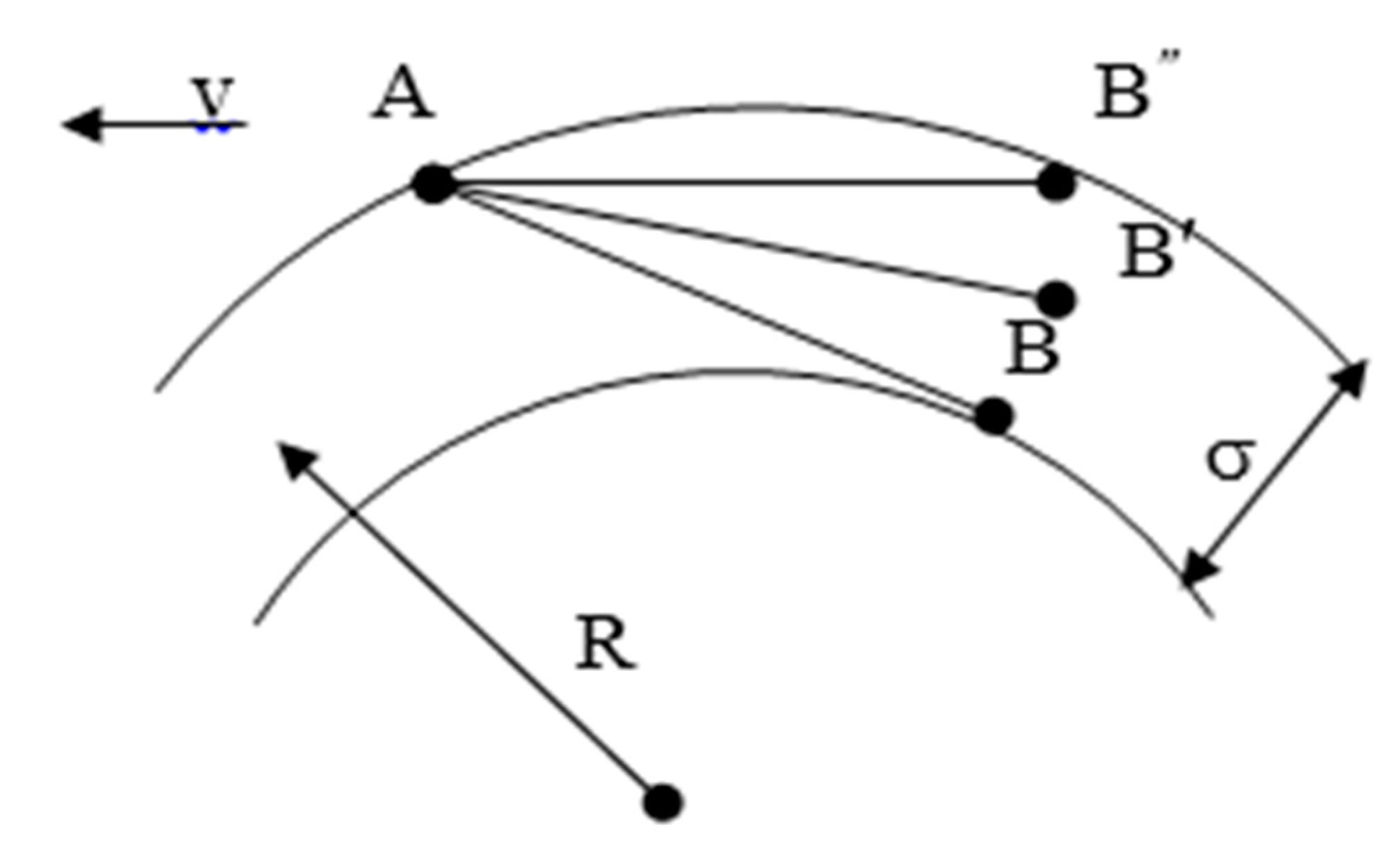
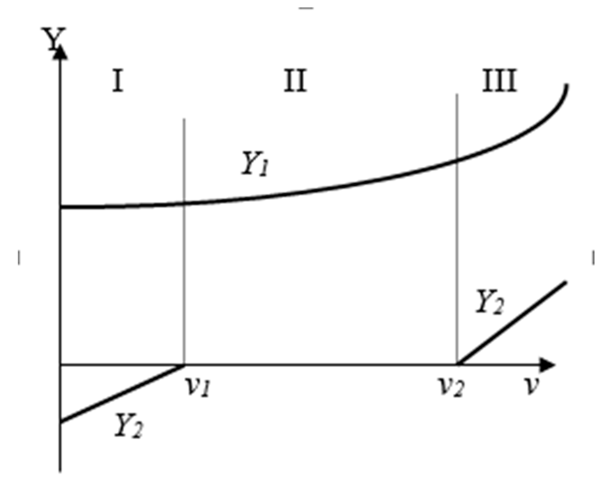
- АB – maximum crossing (σb = σ = Δ + δ);
- AB’ – free settling (0 ≤ σb ≤ δ);
- AB’’– maximum displacement (σb = 0).
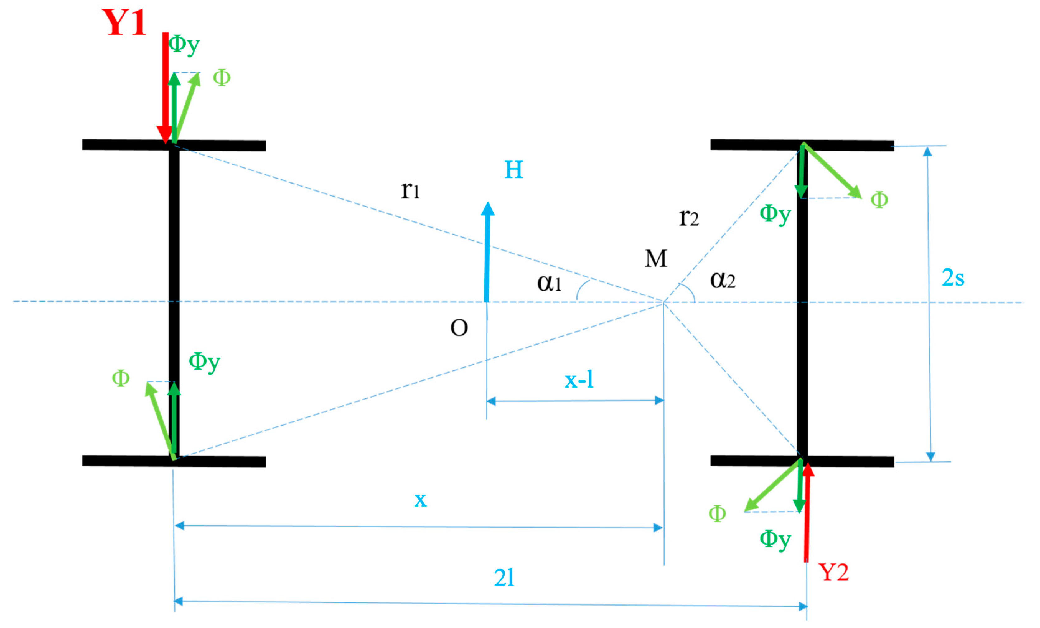
- The transverse force H is induced by the centrifugal (Нc) and wind (Нw) forces. It is applied at the mass center of the wagon and is determined by the equation (5):
- 2.
- The centrifugal force is defined by the Equation (6):
- 3.
- The wind force is determined by Equation (7):
- 4.
- The frictional forces Ф obtained because of the rotation around the pole M are determined by the Equation (8):
- 5.
- The total reactions Yi from rails on the wheelset i are obtained from the equilibrium conditions ΣY=0 and ΣММ=0, according to equations system (10):
2.2. Methodology for theoretical determination of the horizontal load force between the inner (non-attacking) wheel Yji of the investigated wheel axle and the inner rail
2.3. Methodology for theoretical determination of the smallest value of the vertical reaction of the wheel Qjk,,min calculated during torsion of the wagon frame
- 2.
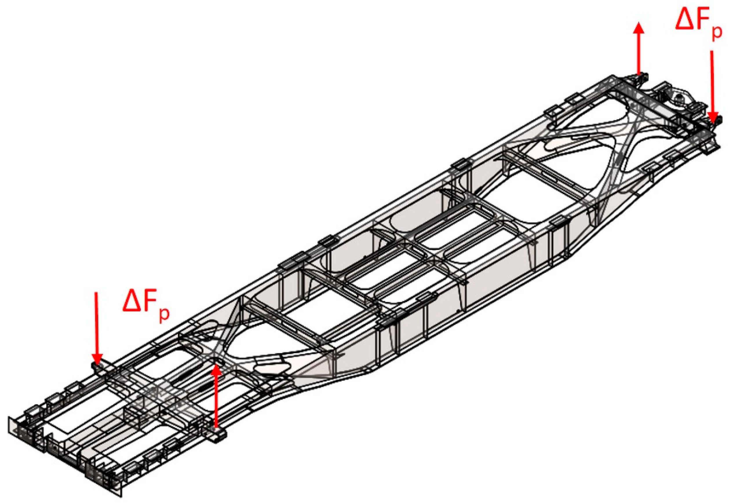
- In accordance with EN 14363 [9], the minimum deflection of the frame Δz* is determined, which should be reached during real (in-situ) testing of the wagon. It is determined by Equation (18) subject to requirement (19). 2a* in this case is valid for wagon frames with pivot distance between 4 and 30 meters.
- 3.
- Recalculation of the force ΔFp from step 1 for loading the wagon frame to achieve the minimum deflection Δz* according to the Equation (20):
- 4.
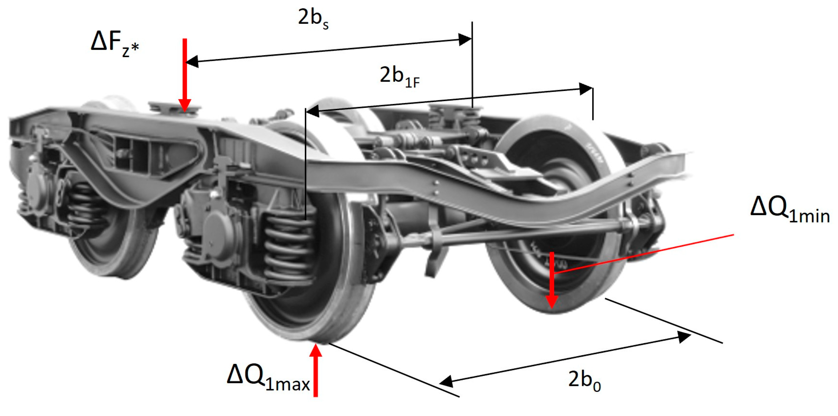
- The force ΔFz* is than transmitted from the lateral support to the side beams of the bogie with a value of ΔF`z*max and ΔF`z*min according to Equations (21) and (22). The corresponding distances b1F and bs are shown in Figure 9.
- 5.
- The minimum value of the wheel reaction Qjk,,min is determined by the Equation (27) and the maximum value by the Equation (28) respectively:
3. Results from the theoretical derailment safety assessment
- Tare weight of the wagon: 27,5 t;
- Curve radius: R = 150 m;
- Clearance between flanges and rail threads in a straight section of the track, equal to δ = 0,01 m;
- Additional tracks widening in a curved section δ = 0,002 m (in accordance with the test data of the wagon [16]);
- Coefficient of friction between the rail and the wheel μ = 0,4;
- Wheel axle distance a+ = 1,8 m;
- Pivot distance (for one wagon section only) a* = 11,995 m;
- Speed of passing through the curve v = 7 km/h (in accordance with the test data of the wagon [16]);
- Wind pressure W = 0 N/m2 (in accordance with the test data of the wagon [16]);
- Distance between the rolling circles of the two wheels of the same axle 2b0 =1,5 m;
- Transverse distance between the axle journals 2bjF = 2,0 m;
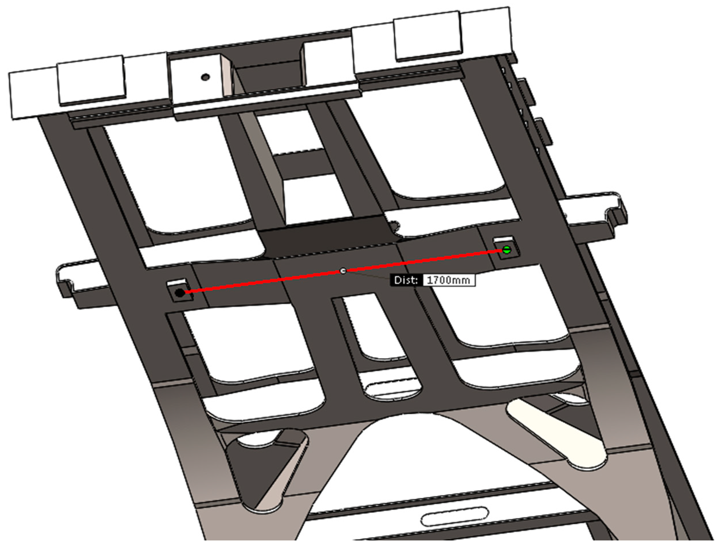
- Distance between the side supports on the bogie 2bs = 1,7 m;
- Overhang of the outer rail h = 0,15 m;
- Earth acceleration g = 9,81 m/s2.
4. Discussion
Author Contributions
Funding
Institutional Review Board Statement
Informed Consent Statement
Data Availability Statement
Acknowledgments
Conflicts of Interest
References
- Wilson, N.; Fries, R.; Wittea, M.; Haigermoser, A.; Wrang, M.; Evans, J.; Orlova, A. Assessment of safety against derailment using simulations and vehicle acceptance tests: A worldwide comparison of state-of-the-art assessment methods. Veh. Syst. Dyn. 2011, 49, 1113–1157. [Google Scholar] [CrossRef]
- Hertz, H. Über die Berührung fester elastischer Körper. Jour. reine angew. Math. 1881, 92, 156–171. [Google Scholar]
- Klingel, W. Über den Lauf Eisenbahnwagen auf Gerarder Bahn. Organ Fortscr. Eisenbahnwesens, 1883, 20, 113–123. [Google Scholar]
- Nadal, M. J. , Locomotives a Vapeur, 1st ed; Collection Encyclopedie Scientifique: Paris, France, 1908. [Google Scholar]
- Kardas-Cinal, E. Selected problems in railway vehicle dynamics related to running safety. Arch. of Trans., 2014, 31, 37–45. [Google Scholar] [CrossRef]
- Zeng, J.; Guan, Q. Study on flange climb derailment criteria of a railway wheelset. Veh. Syst. Dyn., 2008, 46, 239–251. [Google Scholar] [CrossRef]
- Zeng, J.; Wu, P. Study on the wheel/rail interaction and derailment safety. Wear, 2008, 265, 1452–1459. [Google Scholar] [CrossRef]
- Konowrocki, R.; Chojnacki, A. Analysis of rail vehicles’ operational reliability in the aspect of safety against derailment based on various methods of determining the assessment criterion. Maint. and Reliab 2020, 22(1), 73–85. [Google Scholar] [CrossRef]
- EN 14363:2016; Railway applications – Testing and Simulation for the acceptance of running characteristics of railway vehicles – Running Behaviour and stationary tests. European Committee for Standardization: Brussels, Belgium, 2016.
- UIC CODE 518: Testing and approval of railway vehicles from the point of view of their dynamic behaviour – Safety - Track fatigue - Running behaviour. 5th edition, Paris, September 2009.
- Boronenko, Y.; Orlova, A.; Iofan, A.; Galperin, S. Effects that appear during the derailment of one wheelset in the freight wagon: simulation and testing, Veh. Syst. Dyn., 2006, 44, 663–668. [Google Scholar] [CrossRef]
- Evans, J.; Berg, M. Challenges in simulation of rail vehicle dynamics, Int. Jour. Veh. Mech. Mob., 2009, 47, 1023–1048. [Google Scholar]
- Stoliov, V.; Slavchev, S. Wagons (in Bulgarian), 1st ed; ; Technical University Sofia: Sofia, Bulgaria, 2014; pp. 150–156. ISBN 978-619-167-135-9. [Google Scholar]
- UIC CODE 432: Wagons. Running speeds. Technical conditions to be observed. 12th ed. Paris, October 2008.
- UIC CODE 530-2: Wagons - Running safety. 7th ed., Paris, December 2011.
- Test report of safety against derailment of Sggmrss wagon. No: LSV 6/19 14.04.2019. Laboratory of rail vehicles, University of Belgrade, 2019.
- Report “Strength analysis of wagon series Sggmrss”. Project-VS Ltd., Sofia, October 2017.

| Radius R (m) | δ (mm) |
|---|---|
| 125 ÷ 150 | 20 |
| 150 ÷ 180 | 15 |
| 180 ÷ 250 | 10 |
| 250 ÷ 300 | 5 |
| Over 300 | 0 |
| Parameter | Value | Remark |
|---|---|---|
| v1 | 58,3 km/h | Methodology from Section 2.1. |
| Y1=Y1a Y1i g* Δz* ΔFp Δzp ΔFz* ΔF’z*, max ΔF’z*, min ΔF’1z*, max ΔF’1z*, min ΔQ1, max ΔQ1, min Qnom Qjk, min Qjk, max |
24,718 kN -14,024 kN 3,251 ‰ 39 mm 50 kN 0,08265 mm 23,59 kN 21,82 kN 1,769 kN 10,909 kN 0,885 kN 12,58 kN -0,7862 kN 22,48 kN 21,695 kN 35,061 kN |
Methodology from Section 2.1. Methodology from Section 2.2. Equation (19) Equation (18) The selected load value for the torsional stiffness test [17] Deflection of the frame under the load ΔFp, determined in [17] Equation (20) Equation (21) Equation (22) Equation (23) Equation (24) Equation (25) Equation (26) Equation (17) Equation (27) Equation (28) |
Disclaimer/Publisher’s Note: The statements, opinions and data contained in all publications are solely those of the individual author(s) and contributor(s) and not of MDPI and/or the editor(s). MDPI and/or the editor(s) disclaim responsibility for any injury to people or property resulting from any ideas, methods, instructions or products referred to in the content. |
© 2023 by the authors. Licensee MDPI, Basel, Switzerland. This article is an open access article distributed under the terms and conditions of the Creative Commons Attribution (CC BY) license (http://creativecommons.org/licenses/by/4.0/).


