1. Introduction
The continuous stirred tank reactor (CSTR) and the plug flow reactor (PFR) are two commonly encountered idealizations of chemical reactors. These models act as constraining factors for the behavior of numerous operational reactors, although various configurations of chemical reactors exist. Chemical reactors are typically considered as the foremost unit operations in a chemical facility [
1].
Continuous stirred-tank reactors (CSTR) are extensively used in various industries and incorporate numerous characteristics of other reactor types. These models are relatively more uncomplicated when compared to models for alternative continuous reactors such as tubular reactors and packed-bed reactors. As a result, a CSTR model is a useful tool for demonstrating modeling principles for chemical reactors. A CSTR model's simplicity makes it easier to comprehend the fundamental concepts of reactor design and operation [
2].
2. Configuration of CSTR controller models
2.1. Mathematical Model of CSTR
The chemical reaction in the liquid phase is irreversible and is expressed algebraically with reactant A and product B, with the rate of reaction dependent on the concentration of component A, following a first-order reaction rate.
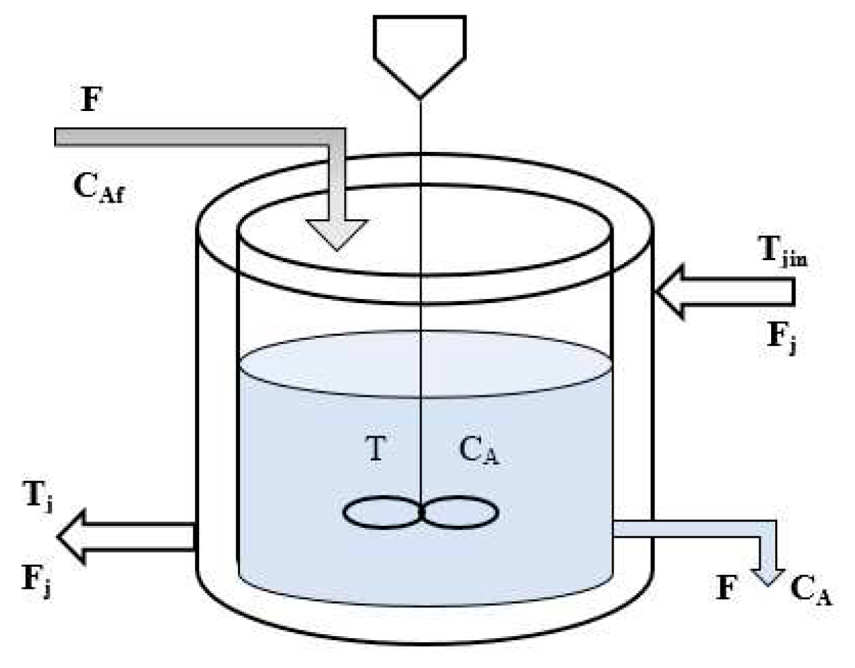
The utilization of a cooling coil in the CSTR schematic diagram (
Figure 1) is shown to control the temperature of the mixture and uphold the desired operating temperature, considering the exothermic reaction and the introduction of pure component A with molar concentration CAi, which is represented using three assumptions.
The CSTR achieves complete mixing.
The mass densities of feed and product streams are equal and constant. They are denoted by .
The liquid volume V in the reactor is kept constant by an overflow line.
Figure 1.
CSTR with cooling jacket.
Figure 1.
CSTR with cooling jacket.
The accumulation rate of material in the reactor is equivalent to the difference between the inflow and outflow rates.
Also, assuming constant volume in the reactor (dV/dt = 0), we find:
If we assume that the density remains constant, then the formula F applies:
The equilibrium in component A, assuming a constant volume reactor, remains unchanged:
The energy balance can be derived by assuming constant volume, heat capacity, and density:
(-ΔH)Vr is the rate of energy contributed by the exothermic reaction. We can write (5) and (6) in the following state variable form:
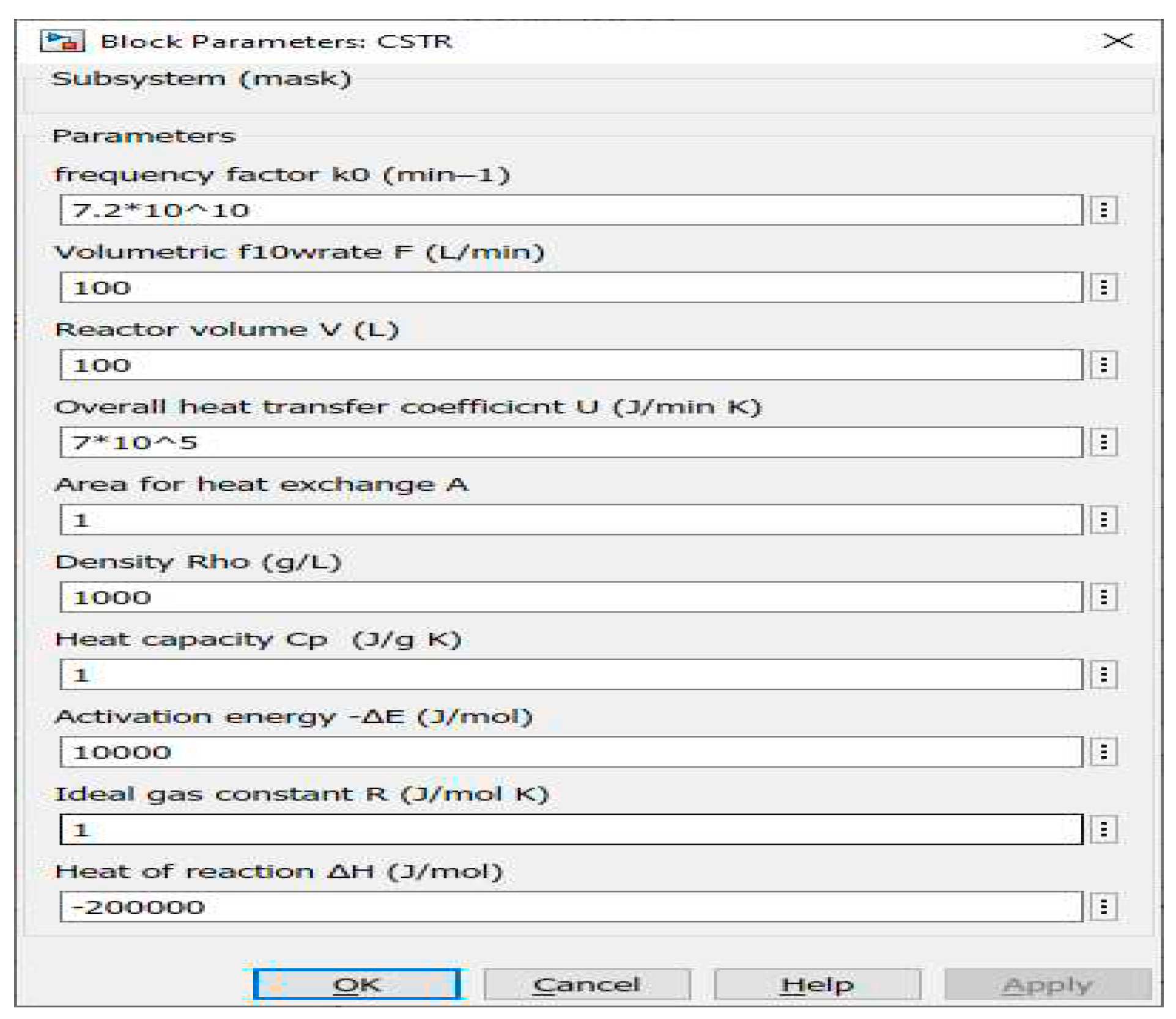
In order to solve equations 7 and 8, it is necessary to specify all the parameters and variables
Figure 2, except for two, namely CA and T. Thus, from the above equations, we can represent a CSTR model by using Simulink and S-function [
1].
Figure 2.
CSTR model Parameters and Values.
Figure 2.
CSTR model Parameters and Values.
2.2. Classical Gain Scheduling
Gain-scheduling, widely used in non-linear control design, has proven effective across various domains including aerospace and process control. Despite the numerous control techniques that are frequently categorized as 'gain-scheduling' approaches, they are typically integrated through a divide-and-conquer design methodology that involves breaking down the non-linear control design task into a series of linear sub-problems. The widespread use of gain-scheduling methods can largely be attributed to the application of the divide-and-conquer approach, which allows for the application of traditional linear design techniques in situations involving non-linear systems. [
3,
4].
Gain scheduling is a methodology utilized to tackle the difficulties presented by non-linear systems, systems distinguished by temporal fluctuations, or circumstances in which control requirements change due to alterations in operational conditions. To utilize this methodology, it is of utmost importance to ascertain quantifiable factors, known as scheduling variables that demonstrate a robust relationship with alterations in the dynamics of the process. These variables may be obtained from different origins, including the measured signal, control signal, or an external signal. Even though gain scheduling can modify parameters other than gain, such as derivative time or integral time, the term "gain scheduling" is still used due to historical reasons. Gain scheduling is an effective approach to controlling systems whose dynamics change due to variations in operating conditions; however, it has been underutilized due to the significant effort required to execute it. When combined with the process of auto-tuning, gain scheduling becomes a simple and efficient technique. [
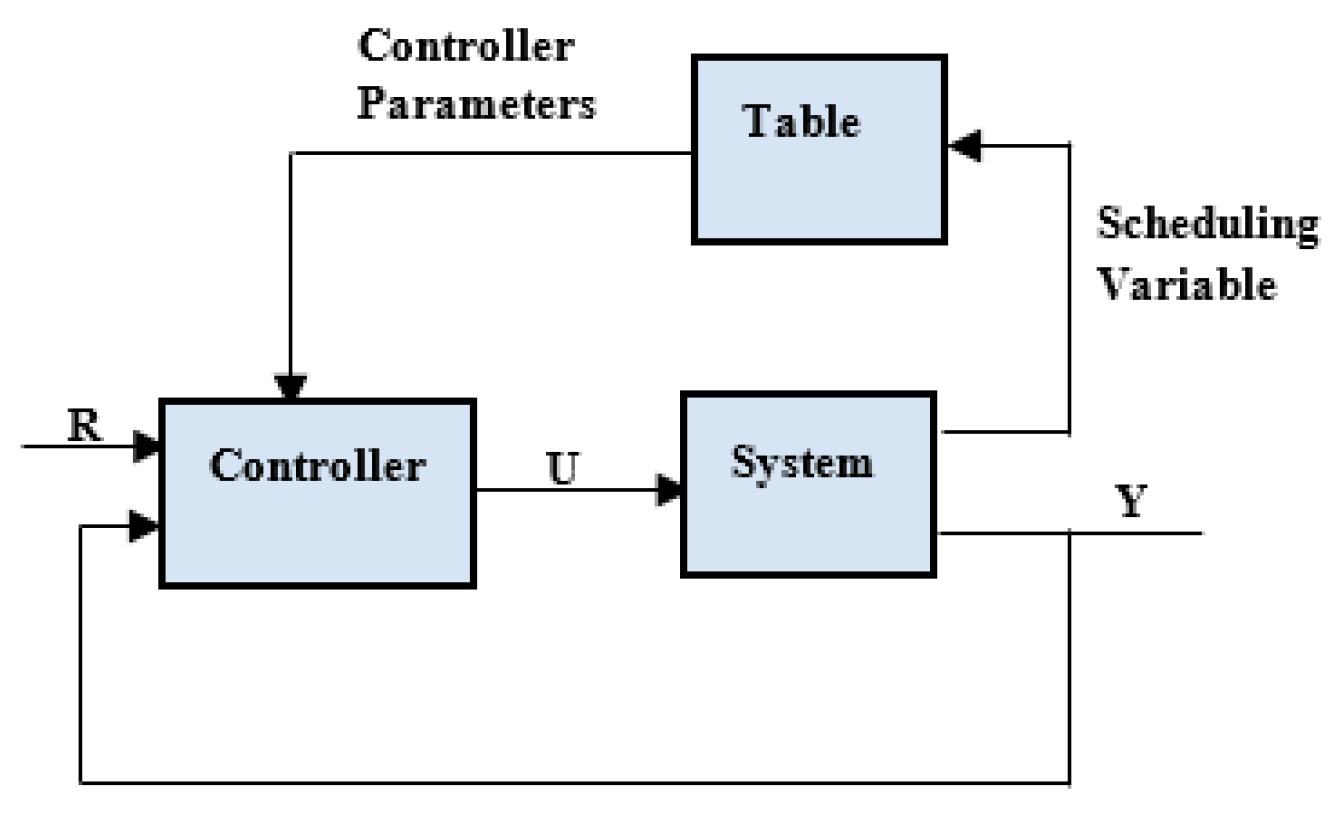
5]. A system that has gain scheduling is depicted in
Figure 3.
Figure 3.
Block diagram of a system with gain scheduling.
Figure 3.
Block diagram of a system with gain scheduling.
The system can be conceptualized as consisting of two loops, namely the inner loop and the outer loop. The former consists of the controller and the process, whereas the latter modifies the controller parameters under the prevailing operating conditions. Although initially utilized for flight control systems, gain scheduling is increasingly being employed in process control, and is now a typical component in some single-loop PID controllers. The utilization of a few sets of controller parameters can lead to significant enhancements in process control applications. In comparison to adaptation, gain scheduling is advantageous since it can adapt to sudden fluctuations in operating conditions. However, the challenge lies in identifying suitable scheduling variables, such as the process variable, external signal, or control signal. In process control applications, the consideration of production rate frequently emerges as a feasible choice, as it is noted that the time constants and delays are generally inversely related to it. The development of a timetable may require a substantial amount of engineering work, however, the presence of automated adjustment can greatly diminish the amount of work that needs to be done. The process of gain scheduling entails identifying a scheduling variable, which is subsequently quantized into various discrete operating conditions. Automatic tuning is then utilized to determine the controller parameters while the process is working under a specific working situation. The previously mentioned parameters are subsequently preserved within a table, and this specific process is repeated until all of the existing operational circumstances have been encompassed. Incorporating gain scheduling into a computer program system is made easy by programming a table to store and recall controller parameters and commands. [
5].
The Classical Gain-Scheduling method involves four primary steps. [
3]:
1. Linear Time-invariant approximations are created for nonlinear plants using Jacobian linearization and LTI control design at a fixed operating point to achieve the desired controller and model properties.
2. The linear system analysis method is used to test the resulting LTI controller and model combinations.
3. The controller coefficients in the gain-scheduling technique are modified in real time based on the current parameter value.
4. Assess and test the overall performance and reliability through simulations on a global level.
Using the gain-scheduling method, the linear system is combined to create the nonlinear CSTR after designing all linear continuous stirred-tank reactors (CSTR) and ensuring system stability despite discretization and delay effects. The gain value for PID is set using a concentration-based look-up table. System stability is assessed through simulation using the nonlinear CSTR model.
2.3. PID Controller
The most widely used control algorithm is the PID controller, which governs the majority of feedback loops and their minor adaptations. The algorithm can be executed independently or as a component of Direct Digital Control software or hierarchical distributed process control systems. [
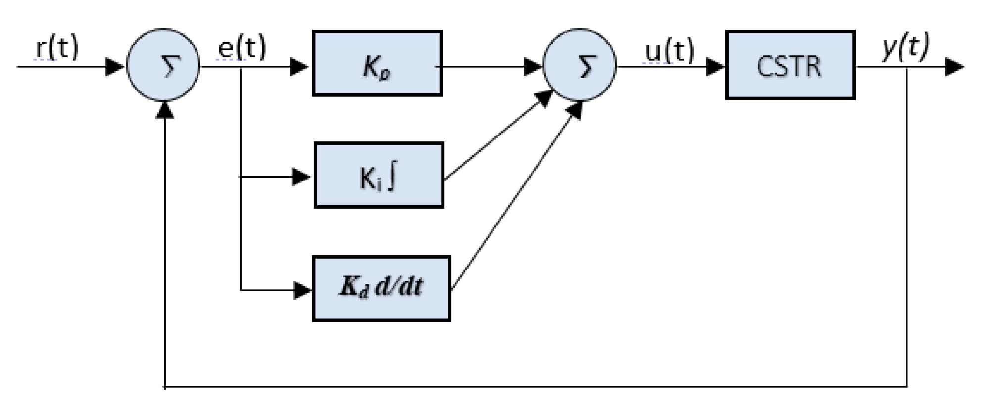
5]. The PID controller is a widely recognized tool in the field of control systems due to its simplicity and ease of implementation. Its output is determined by the following equation.
Where Kp, Ki, and Kd are gains applied to the error signal e(t) and the control signal u(t), respectively:
Where The input signal is represented by r(t) while the output signal is represented by y(t).
The use of PID controllers in industrial process control is common due to their simple design, reliability, and ease of use. Tuning techniques are often applied to improve their efficiency following their widespread adoption,
Figure 4 show PID controller [
6].
Figure 4.
Block diagram of PID control system.
Figure 4.
Block diagram of PID control system.
2.4. Set-Point Weighting PID Controller (SWPID)
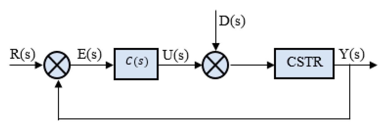
The 1DOF PID controller is used in different industries to modify the steady state and transient response of the closed-loop control system. It accomplishes this by continuously changing the value of U(s) until the difference between the reference input R(s) and process output Y(s) reaches zero, even when there is an external disturbance signal D(s). You can see the structure of this controller in
Figure 5 [
7].
Figure 5.
Shows of 1DOF PID controller.
Figure 5.
Shows of 1DOF PID controller.
The single-degree-of-freedom controller has a coupling between the load disturbance response and a set point response, which results in a poor set point response, but the two-degree-of-freedom controller can decouple these responses effectively through set-point weighting [
10].
The IDOF PID controller performs well in terms of reference tracking and disturbance rejection. However, it may not effectively provide a smooth reference tracking performance for unstable processes due to proportional and derivative kicks. [
10].
To minimize unwanted effects, it is crucial to use a PID structure, particularly the SWPID controller in
Figure 6. It involves tuning five parameters: Kp, Ti, Td, b, and c.
There are three basic forms of 2DOF PID controllers: standard, parallel, and series. The standard and parallel controllers can be designed using three different structures. [
9].
Figure 6.
Structure of set-point weighted PID controller.
Figure 6.
Structure of set-point weighted PID controller.
2DOF PID can be mathematically represented in the following way:
Rewrite equation (12) as:
From equation (13) there are two separate systems in place - one for tracking points and another for rejecting disturbances. Each system can respond independently. The controllers related to the set-point Cs𝑝(s) and output signal Cy(𝑠) are given as follows:
The set-point weights, b, and c, which determine the proportional and derivative actions, are restricted to values between zero and one. Additionally, the integral action error is not assigned any weight to avoid the occurrence of steady-state control error. To obtain various controllers,
Table 1 presents the parameters derived from equation (13).
Table 1.
Set-point weighted PID and modified PID structures.
Table 1.
Set-point weighted PID and modified PID structures.
| Controller structure |
weighting parameter (b) |
weighting parameter (c) |
| PID |
1 |
1 |
| PI-D |
1 |
0 |
| ID-P |
0 |
1 |
| I-PD |
0 |
0 |
| SWPID |
0 < 𝑏 < 1 |
0 < c < 1 |
| SWPI-D |
0 < 𝑏 < 1 |
0 |
| SWID-P |
0 |
0 < a < 1 |
2.5. Fuzzy Gain Scheduling (FGS)
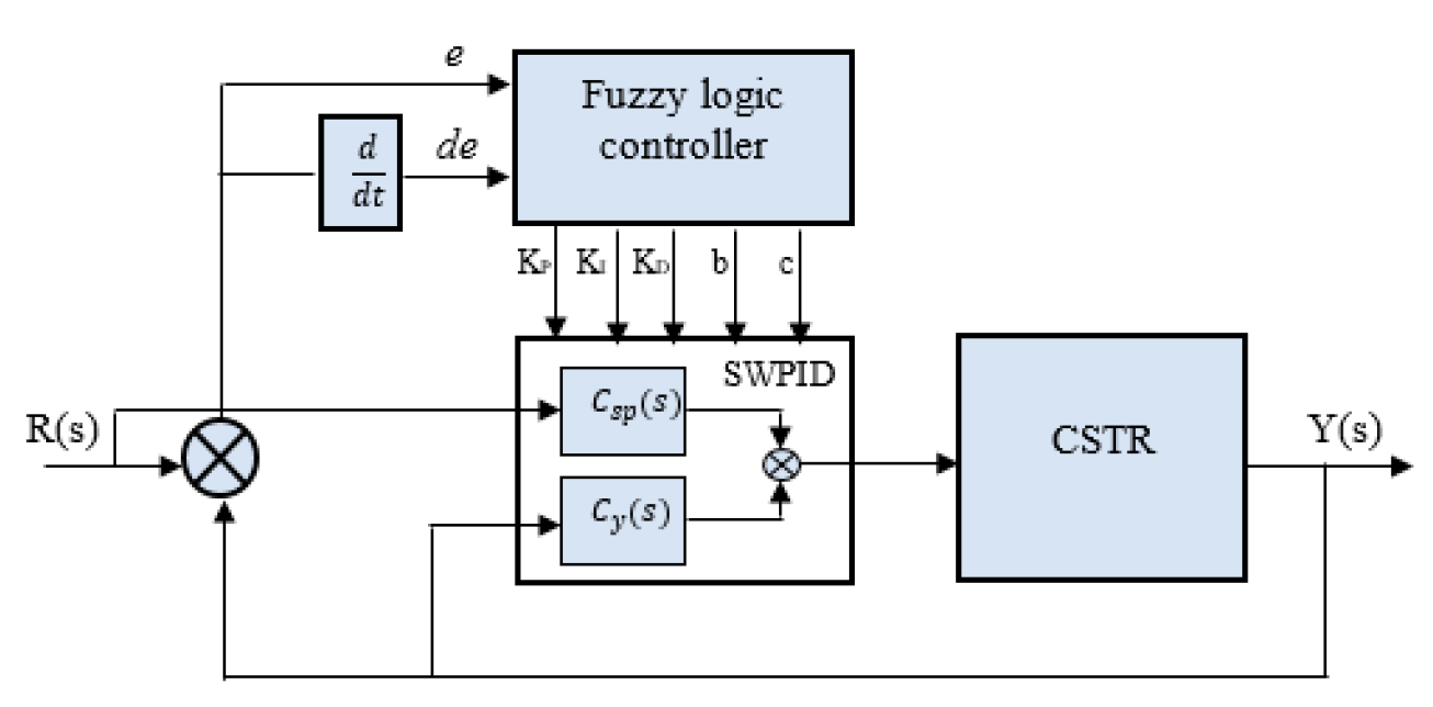
The article presents
Figure 7 to showcase fuzzy logic in SWPID controllers. Table I displays how adjusting the controller parameters affects various aspects such as rise time, settling time, overshoot, steady state error, and stability.
Figure 7.
Structure of set-point weighted PID controller.
Figure 7.
Structure of set-point weighted PID controller.
2.6. Design of the FGS-PID CSTR Controller
The fundamental component of a fuzzy controller is the fuzzy rules, which play a crucial role in dynamically adjusting PID parameters. Therefore, the effectiveness of the entire control system is directly associated with the formulation of these fuzzy rules. Expert designers and engineers draw upon their extensive design experience and accumulated knowledge to develop these rules [
10].
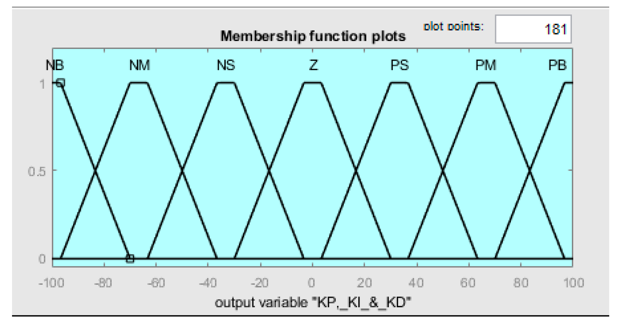
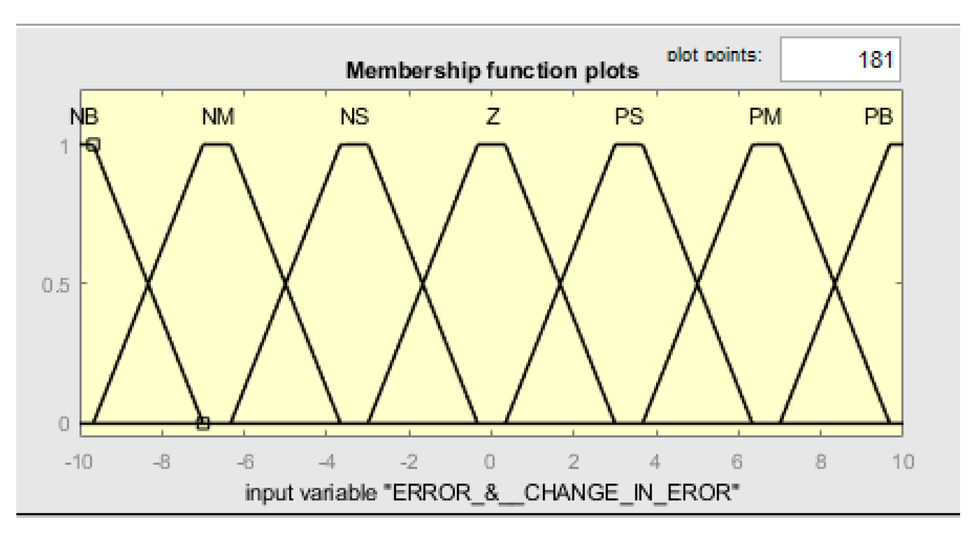
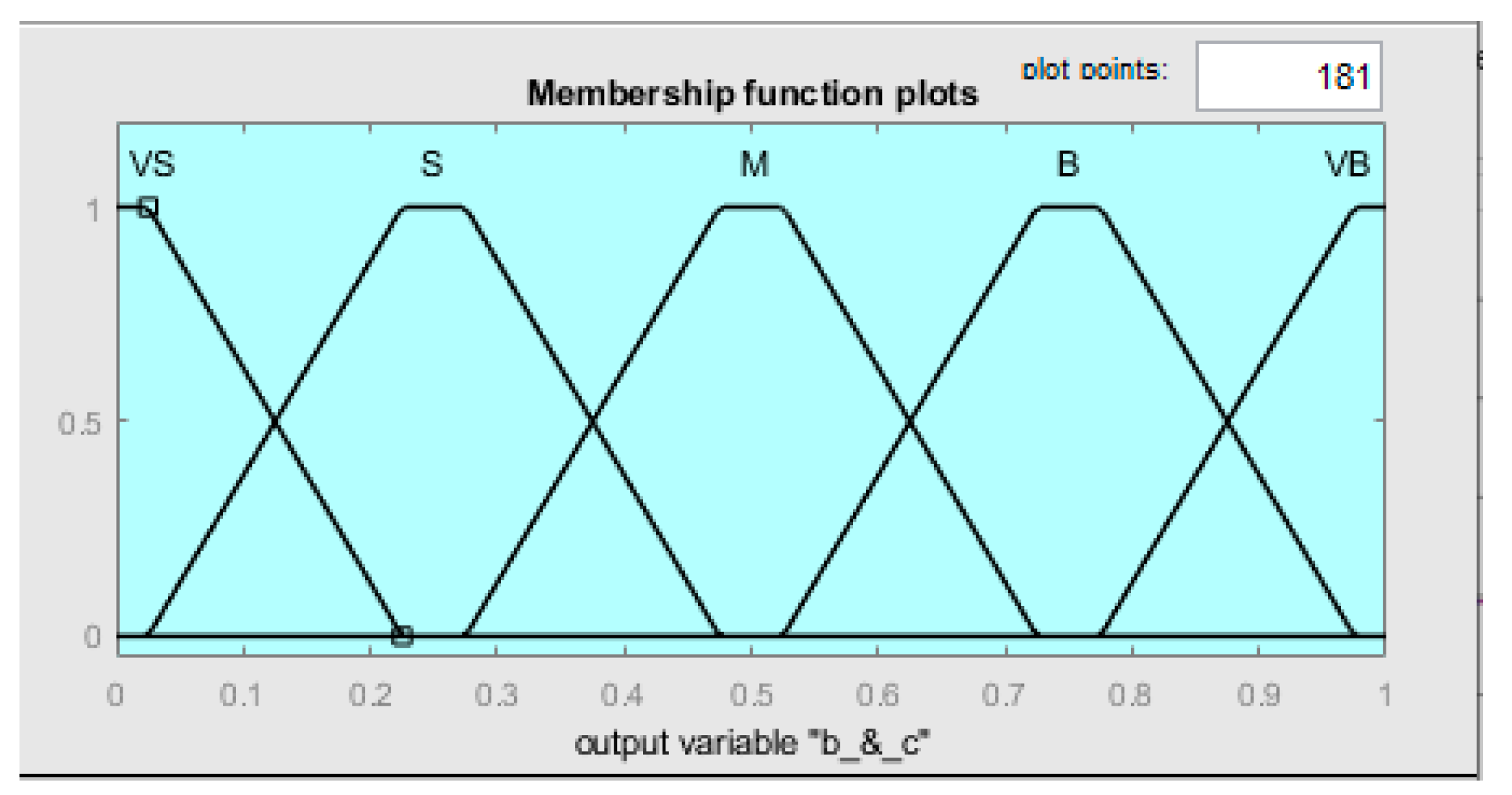
The error e(t) and the change in error ce(t) are utilized as premises in the fuzzy rules to produce multiple outputs, including Kp, Ki, Kd, b, and c. In terms of the input variables, there are a total of seven Gaussian membership functions, while the output variables are described by five and seven triangle membership functions. This information can be observed visually in Figures 8 to 11.
The Mamdani-based fuzzy tuning rules are presented in
Table 3.
Table 2 contains the explanations of the relevance of linguistic variables for the membership function, as illustrated in Figures 8 to 11.
Table 2.
Meaning of the linguistic variables in the fuzzy system.
Table 2.
Meaning of the linguistic variables in the fuzzy system.
| term |
meaning |
term |
meaning |
| Negative Big |
NB |
Very Small |
VS |
| Negative Medium |
NM |
Small |
S |
| Negative Small |
NS |
Medium |
M |
| Zero |
Z |
Big |
B |
| Positive Small |
PS |
Very Big |
VB |
| Positive Medium |
PM |
- |
- |
| Positive Big |
PB |
- |
- |
Table 3.
Fuzzy Control Rules
Table 3.
Fuzzy Control Rules
| e/ce |
NB |
NM |
NS |
Z |
PS |
PM |
PB |
NB
|
PB |
PB |
PM |
PM |
PS |
PS |
Z |
| NB |
NB |
NM |
NM |
NS |
Z |
Z |
| PS |
NS |
NB |
NB |
NB |
NM |
PS |
NM
|
PB |
PB |
PM |
PS |
PS |
Z |
NS |
| NB |
NB |
NM |
NS |
NS |
Z |
Z |
| PS |
NS |
NB |
NM |
NM |
NS |
Z |
NS
|
PM |
PM |
PM |
PS |
Z |
NS |
NS |
| NM |
NM |
NS |
NS |
Z |
PS |
PS |
| Z |
NS |
NM |
NM |
NS |
NS |
Z |
| Z |
PM |
PM |
PS |
Z |
NS |
NM |
NM |
| NM |
NM |
NS |
Z |
PS |
PM |
PM |
| Z |
NS |
NS |
NS |
NS |
NS |
Z |
PS
|
PS |
PS |
Z |
NS |
NS |
NM |
NM |
| NM |
NS |
Z |
PS |
PS |
PM |
PB |
| Z |
Z |
Z |
Z |
Z |
Z |
Z |
| PM |
PS |
Z |
NS |
NM |
NM |
NM |
NB |
| |
Z |
Z |
PS |
PS |
PM |
PB |
PB |
| |
PB |
PS |
PS |
PS |
PS |
PS |
PB |
| PB |
Z |
Z |
NS |
NM |
NM |
NB |
NB |
| Z |
Z |
PS |
PM |
PM |
PB |
PB |
| PB |
PM |
PM |
PM |
PS |
PS |
PB |
Figure 8.
Membership function for outputs KP, KI & KD.
Figure 8.
Membership function for outputs KP, KI & KD.
Figure 9.
Membership function for inputs e & ce.
Figure 9.
Membership function for inputs e & ce.
Figure 10.
Membership function for inputs b & c.
Figure 10.
Membership function for inputs b & c.
The controller parameters in this system are optimized in real time by expert engineers. Conventional PID controller parameters are based on characteristic curves, with corresponding tuning rules. [
10,
12]:
- 1)
When there is a large input error in the controlled object, it can be advantageous to select a larger KP to improve the system's response speed. It is important to be careful when selecting KD to avoid differential saturation caused by an early change in error rate. Selecting KI=0 can help prevent large overshoots.
- 2)
In the case of medium-sized errors and error change rates during normal operation, it is recommended to utilize less control efforts by appropriately decreasing the values of KP, KI, and KD.
- 3)
To ensure stability in a system, increasing KP and KI can be appropriate when the feedback error is small, while the value of KD is crucial to prevent oscillation near the set value, with larger KD being suitable for the low error rate of change and smaller KD for the large error rate of change.
In the situation where factors b and c need to be updated based on performance measures such as peak overshoot, rise time, and amplitude, adjustments can be made according to the values of e and ce,
Table 4. For example,
If e is (PB, PM, or PS) and ce is (NB, NM, or NS), then b is B and c is S.
As a result, the scaling factor Kp increases while the scaling factor Kd decreases.
Alternatively, if e is NB and ce is Z, then b is S and c VB.
Leading to an increase in the input scaling factor Kd. Similar rules can be applied to other scenarios [
11].
Table 4.
Rule base for b and c.
Table 4.
Rule base for b and c.
| e/ce |
NB |
NM |
NS |
Z |
PS |
PM |
PB |
NB
|
VS |
S |
M |
VB |
M |
S |
VS |
| M |
VS |
VS |
VS |
VS |
VS |
VB |
NM
|
VS |
S |
S |
M |
S |
S |
VS |
| M |
M |
VS |
VS |
VS |
M |
VB |
NS
|
VS |
VS |
S |
S |
S |
VS |
VS |
| M |
M |
M |
VS |
M |
VB |
VB |
| Z |
VS |
VS |
VS |
S |
VS |
VS |
VS |
| M |
M |
M |
M |
VB |
VB |
VB |
PS
|
VS |
VS |
S |
S |
S |
VS |
VS |
| VB |
VB |
M |
VS |
M |
VB |
VB |
| PM |
VS |
S |
S |
M |
S |
S |
VS |
| |
M |
M |
VS |
VS |
VS |
M |
VB |
| PB |
VS |
S |
M |
VB |
M |
S |
VS |
| M |
VS |
VS |
VS |
VS |
VS |
M |
3. Results and Discussion
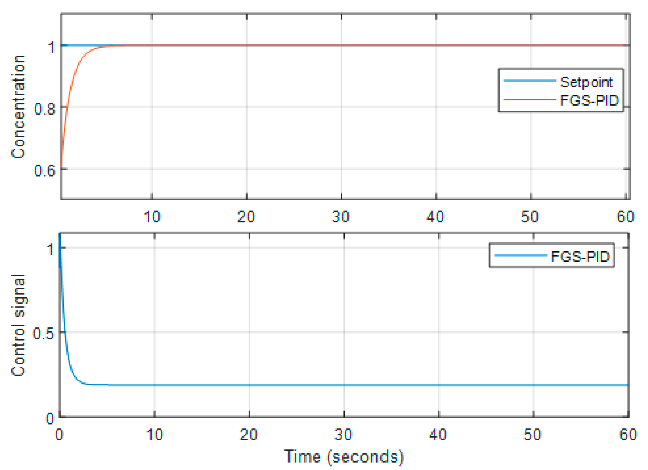
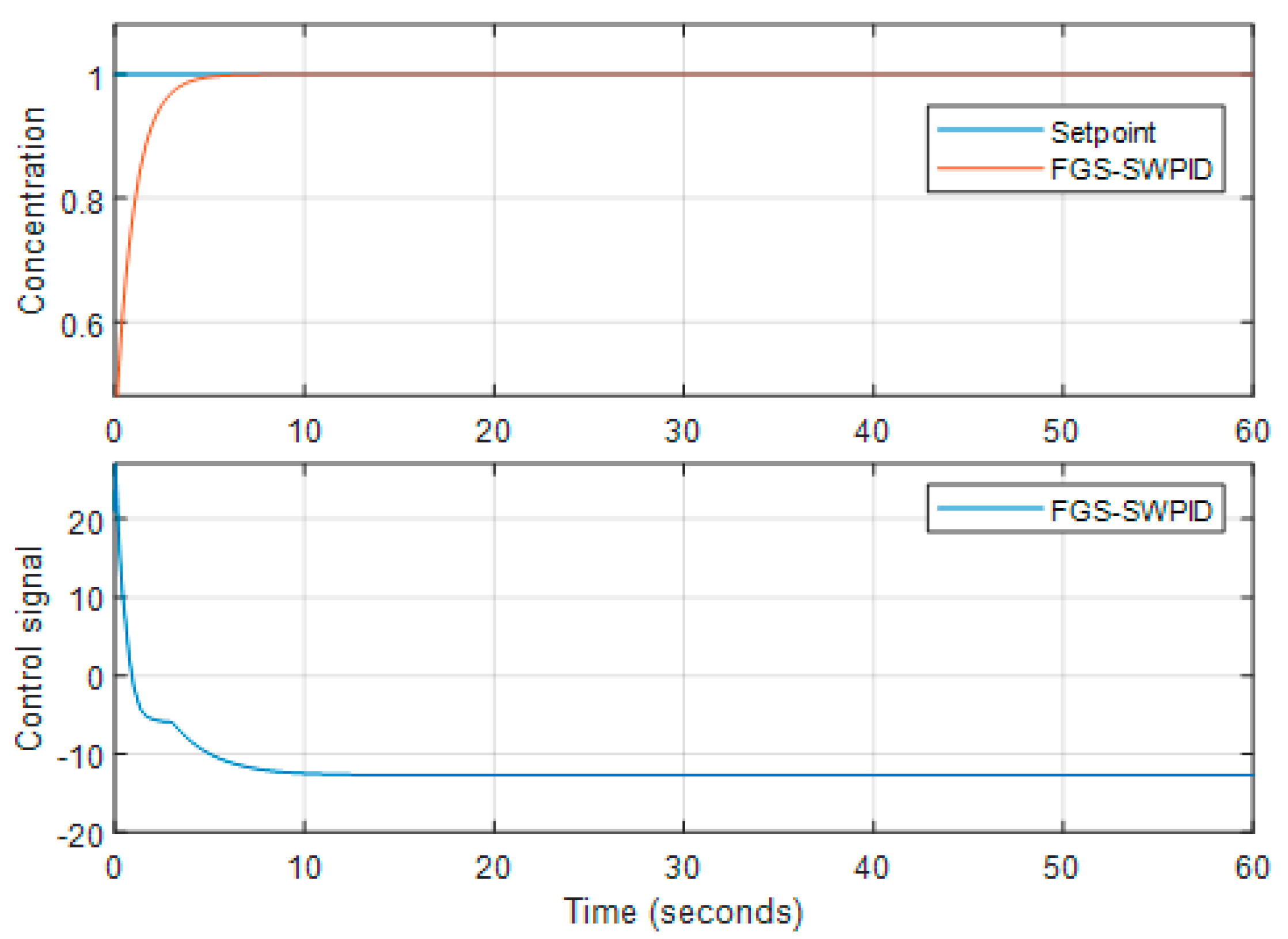
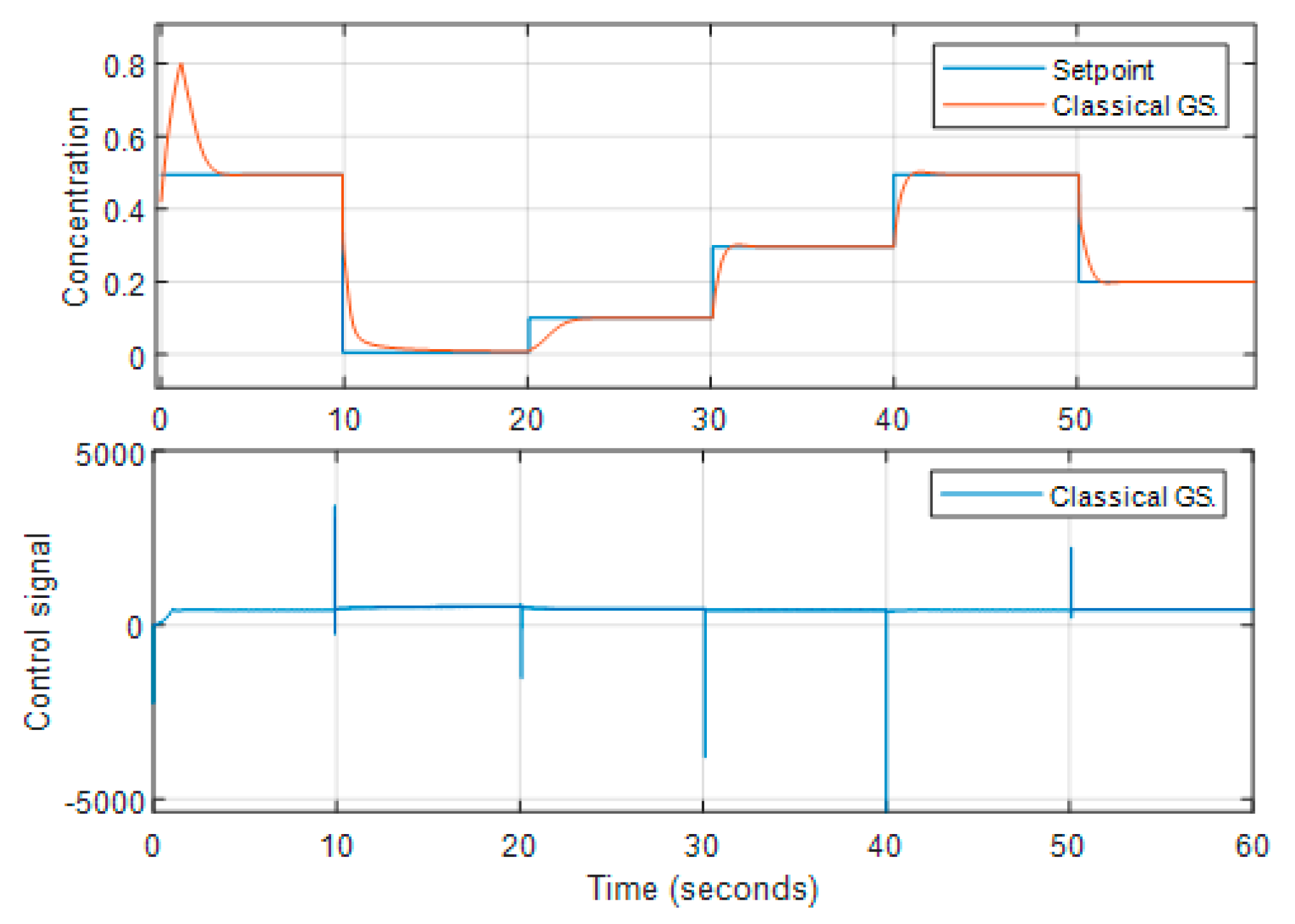
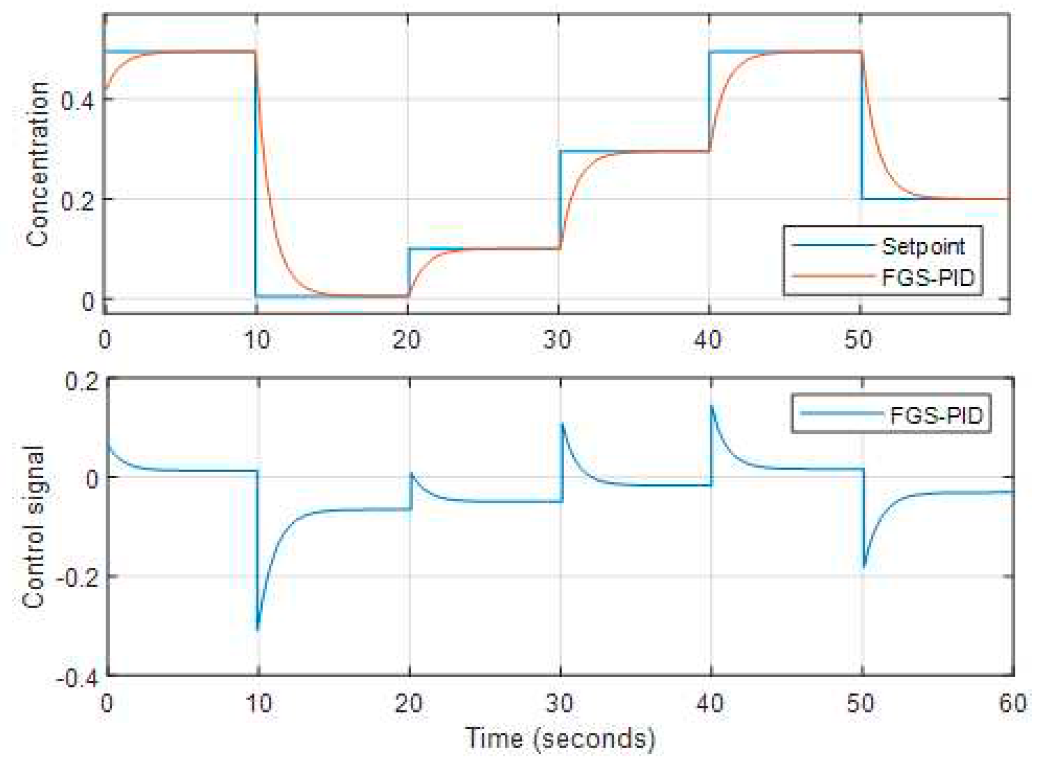
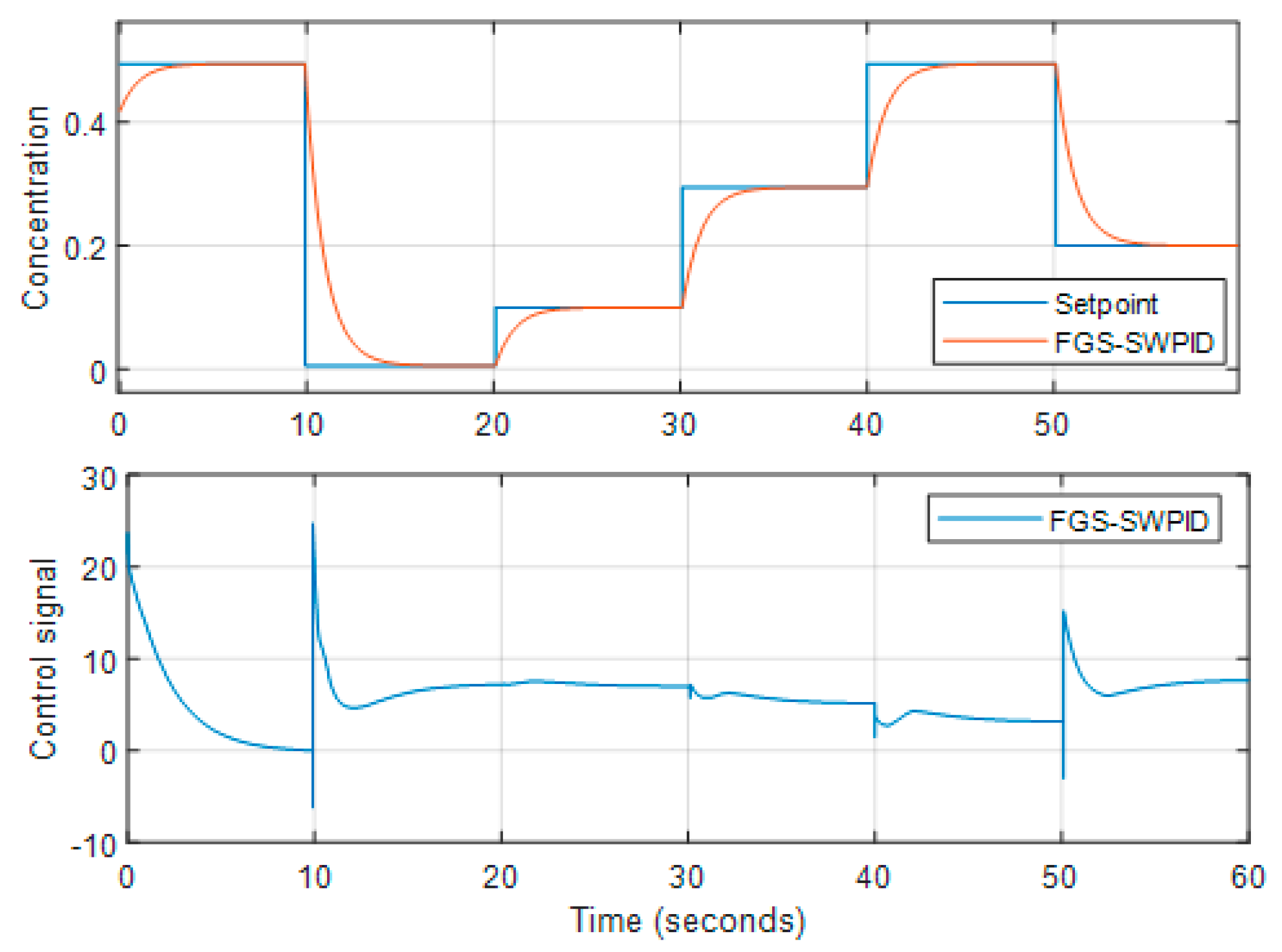
To assess the effectiveness and robustness of the control system, it is imperative to analyze both the performance of set-point tracking as well as disturbance rejection tracking. The observations presented in Figures 11 to 15 demonstrate that the gain scheduling approach is highly effective in tracking changes in set-point, while the PID method exhibits slower response times. These observations provide valuable insights into the control system's ability to adapt to changing conditions and maintain Stable performance.
The control signal for the isothermal CSTR using FGS-based PID and SWPID controllers is shown and analyzed in
Figure 11 and
Figure 12, respectively.
Figure 11.
The unit step performance of the CSTR with FGS-PID.
Figure 11.
The unit step performance of the CSTR with FGS-PID.
Figure 12.
The unit step performance of the CSTR with SWFGS-PID.
Figure 12.
The unit step performance of the CSTR with SWFGS-PID.
The FGS-SWPID shows superior set-point tracking and disturbance rejection in comparison to the FGS-PID.
Table 5 presents the evaluation of rise time and overshoot.
Table 5.
Performance Analysis for Isothermal CSTR.
Table 5.
Performance Analysis for Isothermal CSTR.
| Parameter |
FGS-PID |
FGS-SWPID |
| Rise time |
2.163 s |
2.160 s |
| Overshoot |
0.500% |
0.498% |
Figures 13 to 15 show the set-point tracking performance. From the Figures, we can observe that FGS-SWPID tracks the set-point change very well; FGS-PID is slower; and classical gain shows some overshoots when the set-point is raised.
Figure 13.
The set-point tracking performance of the CSTR with gain scheduling.
Figure 13.
The set-point tracking performance of the CSTR with gain scheduling.
Figure 14.
The set-point tracking performance of the CSTR with FGS.PID
Figure 14.
The set-point tracking performance of the CSTR with FGS.PID
Figure 15.
The set-point tracking performance of the CSTR with FGS.SWPID
Figure 15.
The set-point tracking performance of the CSTR with FGS.SWPID
5. Conclusions
In this paper, a fuzzy gain scheduling mechanism is used to adjust controller gains for isothermal CSTR process models online. The FGS-SWPID controller's effectiveness is evaluated by comparing its set-point tracking and disturbance rejection abilities with FGS-PID and classical gain scheduling PID mechanisms. After analyzing simulation results, it is evident that the FGS-SWPID offers better performance in terms of overshoot and rise time compared to both FGS-PID and classical gain scheduling PID mechanisms. However, the controller's ability to reject disturbances remains consistent and satisfactory.
References
- Dale E. Seborg, Thomas F. Edgar, Duncan A. Mellichamp, Francis J. Doyle III "Process Dynamics and Control", Fourth Edition.
- B. Wayne Bequette "PROCESS DYNAMICS Modeling, Analysis, and Simulation" Rensselaer Polytechnic Institute.
- Made Widhi Surya Atman, Bambang Riyanto Trilaksono, "Gain-Scheduling Design for Three-loop Attitude Control System" 2014 IEEE 4th International Conference on System Engineering and Technology (ICSET) November 24-25, 2014 Bandung – Indonesia.
- D. J. Leith & W. E. Leithead (2000) Survey of gain-scheduling analysis and design, International Journal of Control, 73:11, 1001-1025. [CrossRef]
- Karl J. Astrom and Tore Hagglund, PID Controllers Theory, Design, Tuning, 2nd Edition.
- Sharma, Kartik, and Dheeraj Kumar Palwalia. "A modified PID control with adaptive fuzzy controller applied to DC motor." 2017 International conference on information, communication, instrumentation, and control (ICICIC). IEEE, 2017. [CrossRef]
- Rajinikanth, V., and K. Latha. "Setpoint weighted PID controller tuning for unstable system using heuristic algorithm." Archives of Control Sciences 22.4 (2012): 481-505. [CrossRef]
- Wu, Hang, Weihua Su, and Zhiguo Liu. "PID controllers: Design and tuning methods." 2014 9th IEEE Conference on industrial electronics and applications. IEEE, 2014. [CrossRef]
- Viteckova, Miluse, and Antonin Vitecek. "Standard, parallel and series two degree of freedom PID controllers." 2019 20th International Carpathian Control Conference (ICCC). IEEE, 2019. [CrossRef]
- Youn, Bo, and Dongwei Sun. "Fuzzy PID control technology for synchronous generator excitation." International Journal of Control and Automation 8.10 (2015): 91-98. [CrossRef]
- Chopra, Seema, R. Mitra, and Vijay Kumar. "Autotuning of fuzzy PI type controller using fuzzy logic." International journal of computational cognition 6.1 (2008). [CrossRef]
- Eltag, Khaled, Muhammad Shamrooz Aslamx, and Rizwan Ullah. "Dynamic stability enhancement using fuzzy PID control technology for power system." International Journal of Control, Automation and Systems 17 (2019): 234-242. [CrossRef]
|
Disclaimer/Publisher’s Note: The statements, opinions, and data contained in all publications are solely those of the individual author(s) and contributor(s) and not of MDPI and/or the editor(s). MDPI and/or the editor(s) disclaim responsibility for any injury to people or property resulting from any ideas, methods, instructions, or products referred to in the content. |
|
Disclaimer/Publisher’s Note: The statements, opinions and data contained in all publications are solely those of the individual author(s) and contributor(s) and not of MDPI and/or the editor(s). MDPI and/or the editor(s) disclaim responsibility for any injury to people or property resulting from any ideas, methods, instructions or products referred to in the content. |
© 2023 by the authors. Licensee MDPI, Basel, Switzerland. This article is an open access article distributed under the terms and conditions of the Creative Commons Attribution (CC BY) license (http://creativecommons.org/licenses/by/4.0/).
