1. Introduction
AUV are becoming increasingly important in underwater operations such as seafloor exploration and the inspection of pipelines or cables. Their use not only promises cost savings, but also reduces the risks associated with systems that require a human operator on board [
18]. A major challenge in the development of advanced autonomous systems is to create real-time path planning and obstacle avoidance strategies that can effectively guide the vehicle through unstructured environments.
Research in recent times has seen the development of numerous strategies aimed at addressing the intricacies of path planning. Fundamentally, path planning algorithms can be categorized into pregenerative and reactive types [
8]. The former, often known as global path planning algorithms, determines the path prior to the mission’s commencement. Examples include the Free Space Network, which utilizes a directed graph reflecting environmental properties [
9] and the Cell Decomposition approach, which employs an undirected graph based on subdividing the environment into distinct predefined cellular structures [
10]. Another notable technique is the Octree-based method, optimal for three-dimensional environments, although it requires recursive subdivisions of mixed cells [
11]. A notable limitation of these global algorithms is their rigidity in adapting paths during active missions due to their nonreal-time nature, although they excel in delivering collision-free paths.
However, reactive algorithms predominantly employ differential computational methods. The Potential Field method, for instance, traces the gradient of artificially produced potential field lines in an environment. However, this could lead to local minimum challenges, potentially ensnaring the vehicle or producing suboptimal solutions [
12]. Solutions such as the stream function, a variant of the harmony function, have been proposed to counteract this [
23]. This technique has witnessed its applicability in areas like robot navigation, with instances of using hydrodynamic analysis to develop stream functions for intricate geometries [
17]. In particular, most existing research is focused on terrestrial and aerial vehicles, leaving underwater applications relatively unexplored.
The underwater environment presents unique challenges. Communication is hampered due to the restrictive bandwidth in underwater channels. The domain is susceptible to currents and may span worldwide [
13]. Additionally, torpedo-like vehicles exhibit strong non-holonomic characteristics, with path curvature constraints stemming from vehicle controllability and sonar system limitations. The limited literature focusing on the planning of underwater-specific routes accentuates the need for innovative algorithms tailored for these demanding conditions [
14].
Recently, there has been a heightened interest in examining the path planning capabilities of AUVs through research based on streamline principles. For example, Yongqiang et al. [
4] verified the suitability of the stream function for formation control and path planning within multi-agent frameworks. This paradigm also extends to wireless sensor networks, where Wang et al. [
5] advocated the application of the stream function to enhance the coverage of the network. Delving deeper into marine dynamics, To et al. [
6] advanced a local motion plan for underwater vehicles, employing the stream function to increase their maneuverability. Furthermore, Nan et al. [
7] embarked on a rigorous exploration of the path identification algorithm in conjunction with the stream function. W. Cai and et al [
1] propose a fluid mechanics-based obstacle avoidance method for AUVs in 3D IoUT, enhancing energy efficiency and multi-obstacle avoidance through path deformation and energy models. P. Yao and etal [
2] propose an improved IIFDS-based submerged path planning method for autonomous underwater vehicles in intricate ocean settings. The culmination of these studies underscores the pivotal role of streamline-based methodologies in optimizing the functionality of various automated systems.
In this paper, we propose a two-dimensional path planning algorithm based on stream functions tailored specifically for AUV. Many AUVs separate the control of depth from the control of the path, making a two-dimensional path planning approach more feasible than a three-dimensional one. In particular, FLS sensors are used for three-dimensional navigation, but they usually scan in the lateral directions, usually providing data on the xy plane. Consequently, our study emphasizes the application of a two-dimensional stream function. We introduce a streamline function-based technique for single obstacle avoidance and demonstrate, mathematically, that the generated stream path can bypass obstacles without encountering local minima. Subsequently, we define a streamline function for the creation of paths concerning obstacles N and analyze the generated path using established theorems. Ultimately, to validate the effectiveness of the proposed path creation technique, we performed path planning based on the specifications of the FLS sensor implemented in the developed LIG AUV. The performance of the generated path technique was then assessed by interfacing with the onboard control system through simulations.
This paper presents two contributions. First, mathematical analysis of the streamline-based obstacle avoidance algorithm has been conducted, demonstrating that the proposed technique does not encounter a local minimum. Second, the effectiveness of the path planning algorithm has been validated through simulations based on AUV dynamics, using obstacle detection sensors on an actual AUV model.
The subsequent sections of this paper are structured as follows. Section II delves into preliminaries on the stream function and its path-planning applications. Section III explicates the proposed methodology. Section IV presents a case study accompanied by simulation results. Finally, Section V concludes the paper.
2. Preliminaries
The study of flows of incompressible, inviscid and irrotational fluids hinges on the potential function, a fundamental concept that allows for the formal representation of such flows. The stream function, a broader mathematical construct, encapsulates both spatial coordinates and temporal progression. Its existence is intrinsically tied to the principles of continuity and incompressibility that govern fluid dynamics, with empirical observations indicating its presence even in viscous media [
20].
In the framework of infinitesimal increments, denoted as
and
, velocity components aligned to the respective axes, represented as
u and
v, adhere to the following relation:
Here, the velocities
u and
v pertain to the
x and
y directions, correspondingly. The term
epitomizes the vorticity of fluid flow. An irrotational flow within a domain
satisfies
, rendering
a harmonic function within this domain [
16]. Renowned studies affirm the absence of local extremities in harmonic functions [
22], which implies a similar behavior for the stream function.
This work harnesses the representation of the stream function through complex equations. In this context, the marriage between stream and potential functions yields the following complex equation:
Definition 2.1.
Complex Potential Given ϕ and ψ as the velocity potential and stream function describing the irrotational bidimensional movements of an inviscid fluid, the associated complex potential is given by:
This results in the following velocity components:
This relationship precisely aligns with the Cauchy-Riemann equations, signifying that ω operates as a holomorphic function of the complex variable , in regions where ϕ and ψ are singular.
A fundamental proposition in using stream functions within path planning algorithms stems from the inherent ability of the stream function to depict a continuous, smooth trajectory devoid of local extremes. The crux lies in devising a complex stream function sensitive to the positional nuances of obstacles, thereby facilitating an intricate obstacle avoidance technique in alignment with streamlines.
Upon introducing an obstacle into a flow, the incumbent boundary condition necessitates the flow to be tangent to the obstacle’s surface. This is in tandem with the consistent nature of the stream function on an obstacle surface, as maintains uniformity along a streamline. To identify a streamline that envelopes the specified obstacle, one must calibrate the imaginary component of the complex potential function to be consistent.
The subsequent theorem, known as the Circle Theorem, elucidated in [
19], delves into the dynamics of the complex potential with an integrated boundary condition.
Theorem 2.2.
Circle Theorem [19] Consider an irrotational, bidimensional flow of an incompressible inviscid fluid across the z-plane devoid of rigid boundaries. If the complex potential of the flow is denoted by , and all singularities of lie beyond a distance r from a reference point b, then the introduction of a circular cylinder, characterized by its cross-sectional circle C where , alters the complex potential as:
Proof. A detailed proof is articulated in [
19]. □
Here, signifies the conjugate function and is the corresponding conjugate variable in the complex plane. The complex representation of the obstacle b is given by , with and indicating the coordinates of the obstacle x and y, respectively. Analogously, the location z is given by .
The Circle Theorem proffers the capability to compose the vehicle’s stream function using primitives situated in arbitrary locales. A quintessential primitive, especially relevant for AUV, is the sink, denoted by
:
where
denotes the strength of the associated singularity.
Given that the sink is positioned at the origin and an obstacle is situated at
, the complex potential, by invoking Theorem 2.2, becomes:
The ensuing stream function, derived from the imaginary component of equation (2.6), is expressed as:
In the above relation, and denote the stream function components for the sink and the obstacle, respectively.
3. Stream Function Based Obstacle Avoidance Path Planing for Autonomous Underwater Vehicle
3.1. Design of a new stream function for path planning
In the context of this study, we introduce an innovative path-planning technique for AUVs within a two-dimensional plane. Path planning inherently involves three pivotal coordinates: the starting position, the obstacle location, and the goal position. In particular, the stream function expressed in Equation (2.7) omits details related to the destination location, with the starting point anchored at the origin. Consequently, our aim is to derive a novel stream function that encapsulates the target location.
Drawing parallels with the conventional stream function, where the sink primitive represents the start position, we utilize the source primitive to symbolize the goal location. We extend the complex potential function (2.6) to encompass this additional dimension, as:
Here,
and
denote the coordinates of the starting and goal points, respectively. The resultant stream function is thus computed as:
Here, represents the stream function component for the goal point.
Assumption 3.1.
For the purposes of this paper, we operate under the assumption that all obstacles reside between the start and goal positions, thus satisfying:
Where , , , and .
A crucial challenge in the practical deployment of AUVs is related to the measurement methodologies employed. Typically, AUVs harness sonar sensors to identify obstacles. The acoustic signals emitted from these sensors undergo various signal and image processing transformations before manifesting themselves as images. Although a detailed discussion on image processing or the enhancement of sonar performance lies beyond the scope of this work, it is imperative to consider the implications of these pre-processing steps through certain assumptions:
Every obstacle within the search area is identified post pre-processing.
The discerned data include only the position and magnitude of the obstacles.
The preprocessing procedures are sufficiently rapid to facilitate real-time operations.
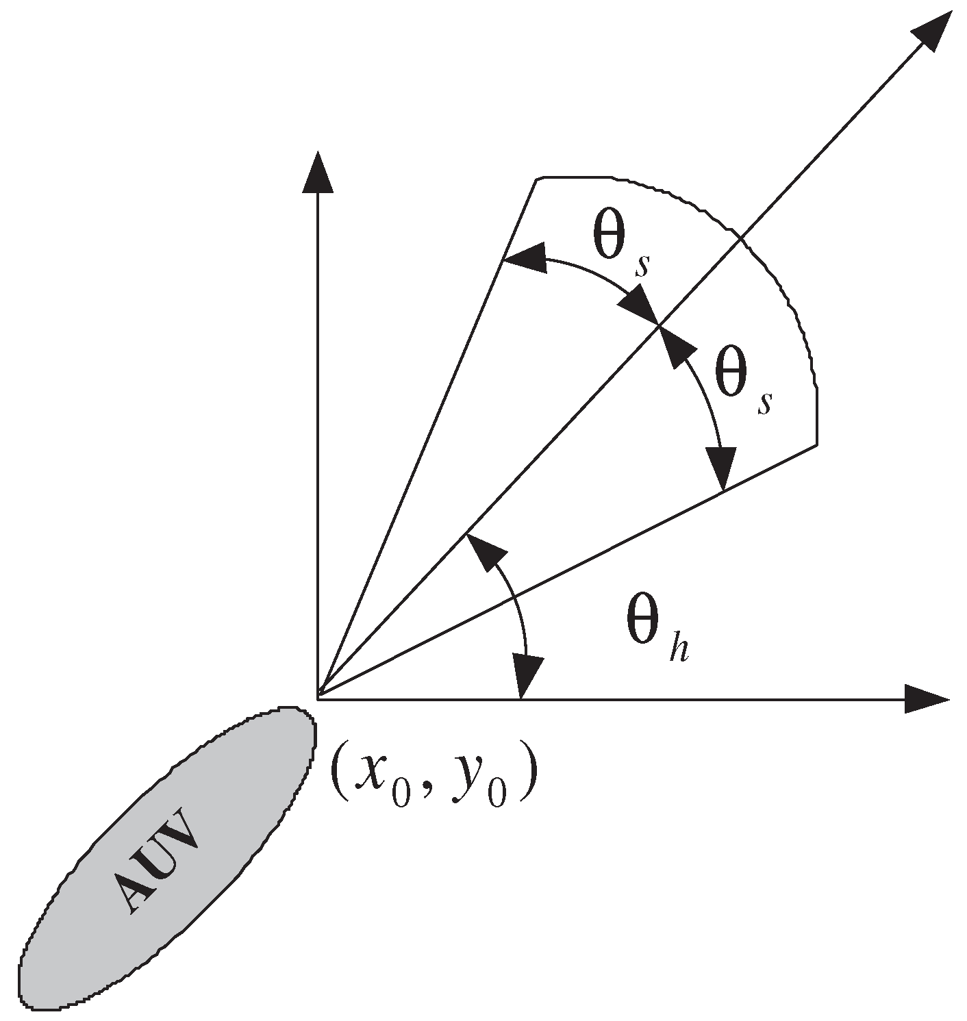
Sonar sensors typically employ a fan-shaped area for their search capabilities. This is pictorially represented in
Figure 1, where the normalized search domain of the sonar is depicted. The fan-shaped zone can be quantitatively characterized by its search range,
and search angle,
. Consequently, the waypoint for an avoidance path can be deduced as:
where
represents the movement step and
is the heading angle. This transformation allows the coordinate elements in the waypoint determination problem to transition from (
x,
y) to (
,
). The primary objective in this study is to determine the optimal heading angle
to ensure that the waypoint
resides in
, given that the movement step
is intrinsically influenced by the vehicle’s speed.
The previously discussed stream function serves as a pivotal determinant of the optimal heading angle. The challenge of determining the heading angle can be mathematically articulated as identifying
:
Here,
is a cost function assigned to evaluate the suitability of each heading angle. An exemplary cost function employing the stream function is:
where
signifies the boundary coordinate of the sonar’s fan-shaped searching zone. This cost function produces the absolute value of the stream function, rendering
as the angle corresponding to the stream function’s minimum value.
To enhance robustness, we propose a histogram-based approach, specifically a radial histogram, for the cost function:
In this equation, represents the radial cluster size, an essential parameter dictating the robustness of the cost function.
3.2. Design of avoidance path planning for single obstacle
Given a scenario in which a single obstacle lies between the starting point (A) and the goal point (B), a multi-waypoint avoidance path can be determined using radial histogram analysis combined with the flow function methodology.
However, employing the stream function presented in equation (2.7) directly as a radial histogram cost function is problematic. The root of the challenge lies in the fact that the cost function outputs the optimal angle that nullifies the stream function’s value. To enhance the radial histogram’s efficacy, we modify the stream function as:
where the function
g is defined as:
Here, denotes the minimum bias value of the obstacle’s stream function.
Theorem 3.2.
Consider an AUV with a maximum radius . Let an obstacle of radius r be positioned at . Let A and B represent the start and goal points with coordinates and respectively. The path avoids obstacles if the following conditions hold:
Here, symbolizes the peak value of the stream function outside the obstacle zone. The waypoints for a collision-free path are given by:
where is as defined below:
Proof. We need to prove two suppositions. The first thing is that there is no collision, and the second thing is that the path starting at A should end at B. Let the cost function
at
has
If
has
,the following relationship is always satisfied,
so, there is no the point
in obstacle region. It means that there is no collision in the obstacle avoidance path. The first proof is done. Let us consider two stream functions in (3.9) such as
where
and
are tangents defined as
Similar to above, obstacle stream function can be rewritten as
where
.Then equation (3.9) is,
The avoidance path is determined by the selecting optimum angle which has minimum value of mean square sum of (3.32). The minimum value of (3.23) is mainly determined by the values of
. which has a minimum value when
. It means that
has minimum at
satisfying,
Equation (3.24) includes the starting point and goal point. Additionally, all streamlines should converge to and because and represent the primitives of the sink and source. Therefore, the second supposition is verified. □
In terms of computational efficiency, it’s pertinent to note that the cost to pinpoint the optimal angle scales with . This implies that the computational overhead is dependent on both the sonar range and the robustness of the chosen path.
3.3. Path Planning Design for Multiple Obstacle Avoidance in Underwater Environments
In underwater environments, AUVs frequently encounter multiple obstacles during mission execution. The stream function-based path planning method, delineated in Theorem 3.2, efficiently handles single obstacle scenarios. By integrating additional stream functions, the approach preserves its properties. Similarly, the representation for multiple obstacles can be deduced as an aggregation of individual obstacle functions.
Theorem 3.3.
Consider an AUV with a maximum radius of . Let its starting point be and the goal point be . Assuming there are n obstacles in the underwater environment, and the k-th obstacle is situated at with a radius . The obstacle avoidance path remains collision-free if the following conditions are met:
The obstacle avoidance path waypoints can then be calculated as:
Proof. The proof strategy is analogous to that of Theorem 3.2. The difference lies in the collision-free condition (3.11) being updated to (3.25) due to a
n-fold increase in the maximum value of
. For a cost function
at a point
, we have:
If
exceeds
, it always satisfies:
This ensures a collision-free obstacle avoidance path. □
4. Simulation Results and Analysis
The proposed streamline-based path planning technique is versatile, with two primary modes of application. First, a global path-planning approach facilitates the generation of obstacle avoidance trajectories in maritime environments teeming with impediments. The salient advantage of paths generated using this technique is their foundation on streamline principles, making them conducive for AUVs to follow with ease. Second, this technique can also be harnessed for local path planning, specifically to create trajectories between waypoints, designed to evade obstacles.
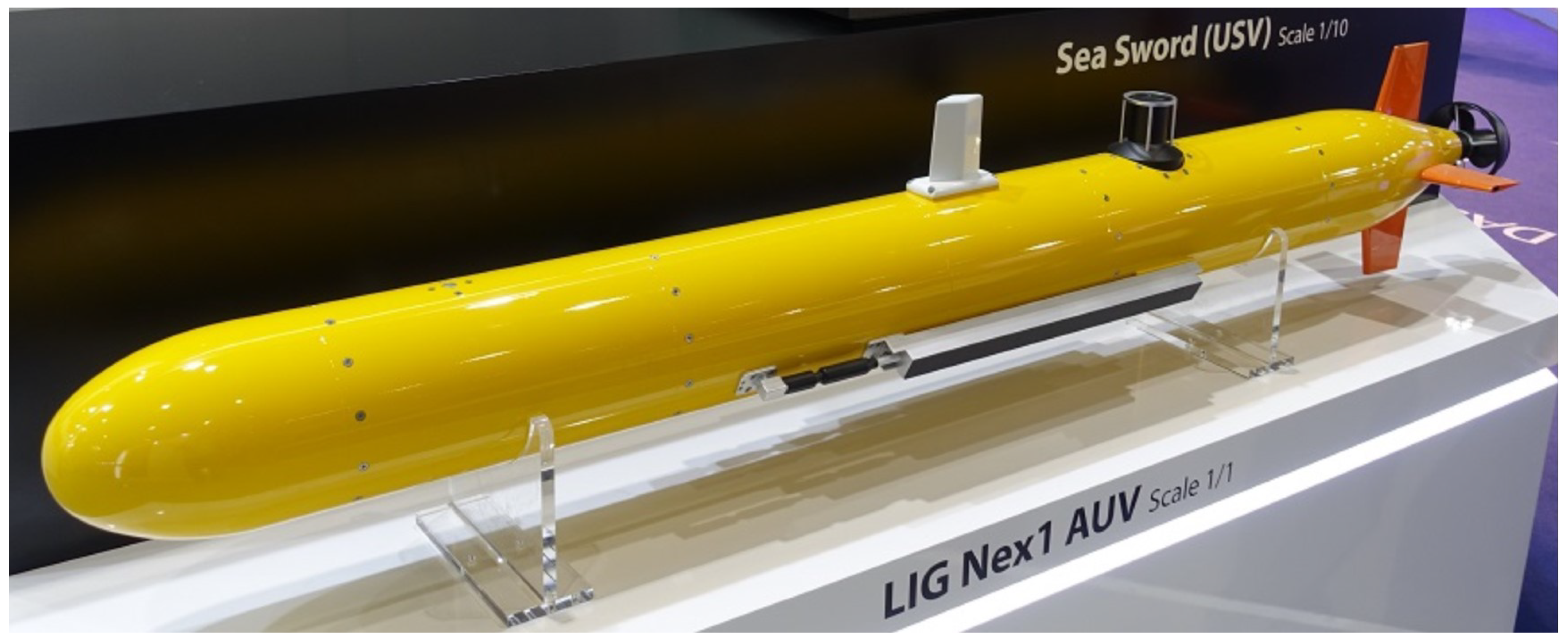
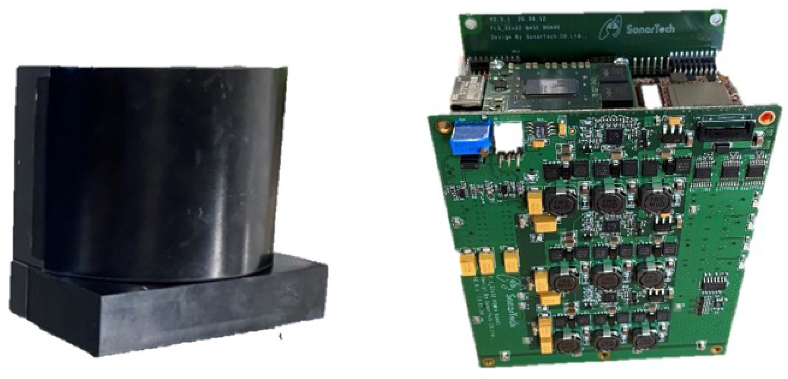
In this study, the characteristics of obstacle avoidance sensors, as developed and integrated into the LIG Nex1 AUV (
Figure 3), were considered. For simulation purposes, obstacle data that mirror real-world conditions was fed, based on these sensors. The employed multi-beam Forward Looking Sonar (FLS) possesses the following specifications:
Feasible operating range: 30m
Horizontal beam width:
Radial cluster size, :
Note that the insonified region of FLS is not included in the simulation results presented. The operational parameters for the AUV are set as a linear velocity of (1 m / s) and an angular velocity cap of .
A comprehensive performance assessment of the path generation algorithm was conducted through simulations. These simulations were designed to both evaluate the algorithm’s efficacy against generic obstacle patterns and test its robustness in overcoming obstacles leading to local minima. The primary objective is to empirically validate its robustness and feasibility. For consistency, each simulation was conducted under the assumption that the dimensions of the underwater environment are (100m × 100m). Furthermore, the AUV is abstracted as a particle with a radius of 2 m. The threshold bias value, , is designated as . This value sufficiently satisfies the condition given by equation (3.11) in Theorem 3.2, particularly as remains below across all underwater environmental points.
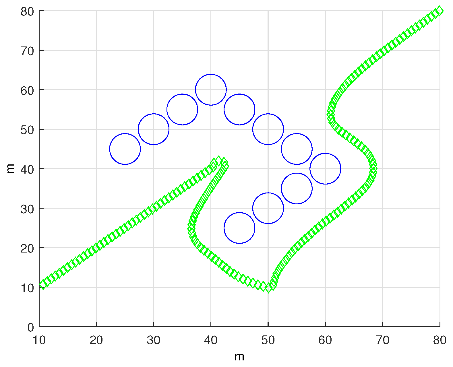
Figure 4 highlights the local minimum dilemma often encountered in potential field methods. Here, the AUV speed is set to (1 m / s) with a sonar operating range of 20m. Traditional potential-field techniques tend to cause the AUV to stall in front of U-shaped obstacles. On the contrary, our proposed stream function-centric approach successfully navigates these challenges, generating smooth paths for obstacle avoidance.
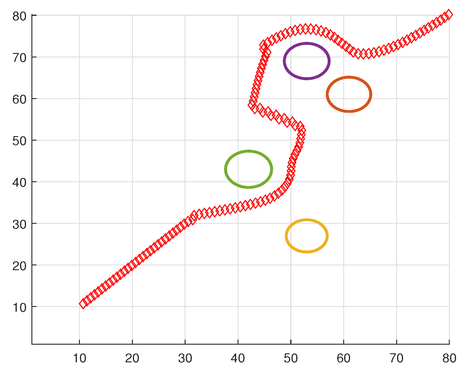
Figure 5 and
Figure 6 represent scenarios with increased navigational complexity. The algorithm consistently produces reliable avoidance paths in the majority of these complicated cases.
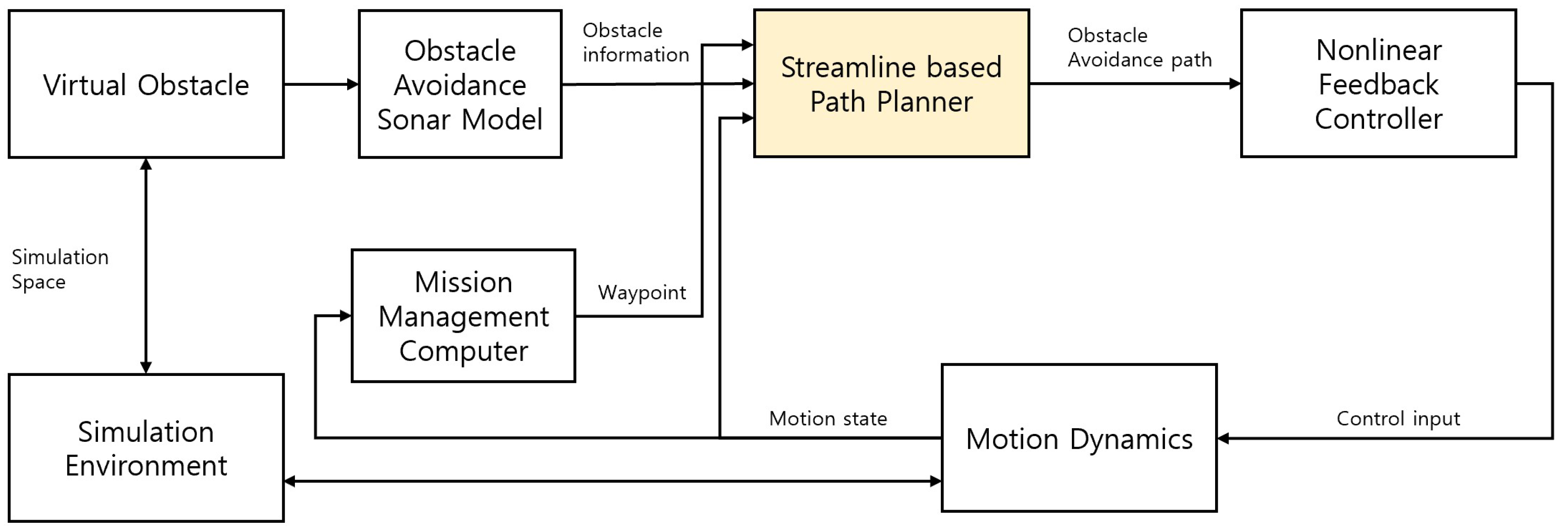
The fidelity of an AUV to adhere to the planned trajectory is crucial. Using the motion model of the LIG Nex1 AUV equipped with an obstacle detection sonar, we analyzed the tracking performance against the obstacles formed in the simulation. This AUV implementation incorporates a nonlinear feedback controller. Although the AUV’s trajectory is three-dimensional, the LIG Nex1 AUV discretely performs depth control and course control. Hence, the proposed streamline control technique was applied exclusively to course control.
Figure 7 shows the entire simulation diagram, including the AUV model and the path planning algorithm.
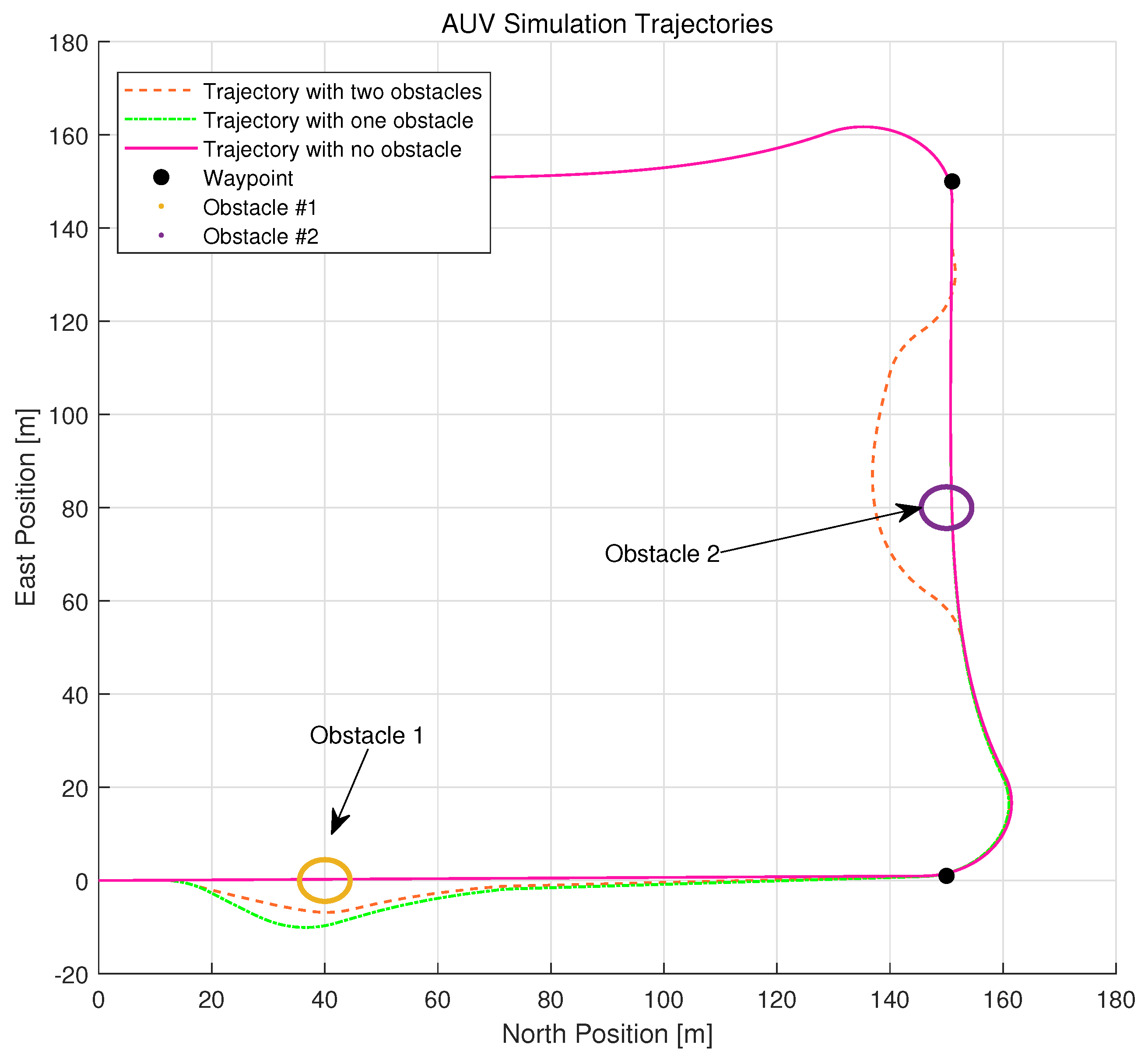
Figure 8 delimits the trajectory comparison in response to incremental obstacle placements. Simulations were executed with the AUV cruising at 4 knots, following waypoints spaced at 150 units. The sonar detection range was set to 30 m, with an FOV of 120 degree. Obstacles were strategically placed between waypoints and consequent trajectory deviations were observed. Another figure (referenced as
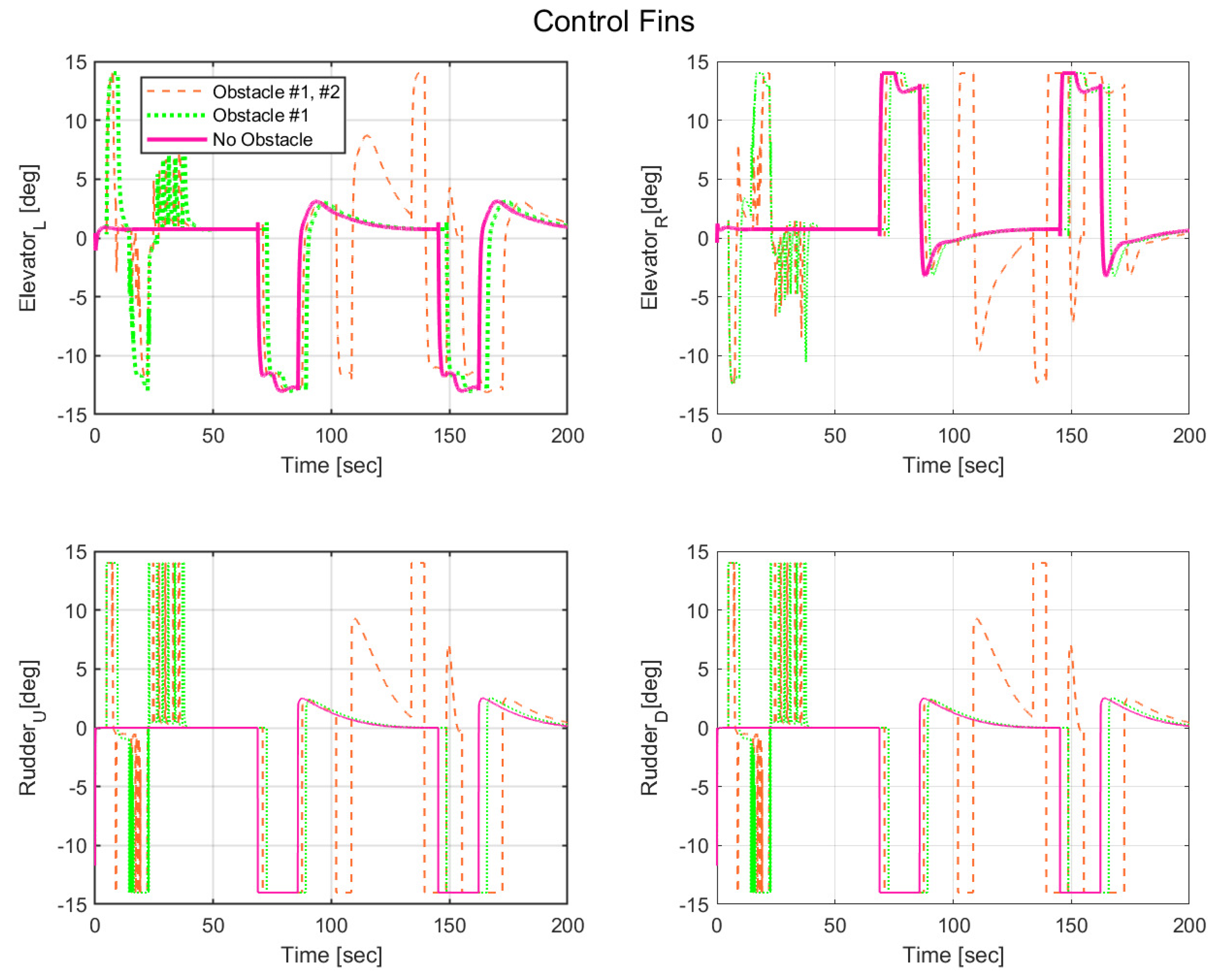
Figure 9) shows the variation in control output based on depth changes due to obstacle avoidance. If a complex path is generated, the control angle is pushed to its limits, potentially resulting in a speed reduction and increased energy consumption. However, the empirical evidence from obstacles 1 and 2 suggests that the proposed streamline-based path planning induces no excessive strain on the AUV’s actual control angle, thereby confirming its potential to produce trajectories that remain within a stable control range.
5. Conclusions
In this study, an improved stream function-based obstacle avoidance algorithm specifically tailored for AUVs has been introduced. Traditional land-based avoidance methods prove insufficient when applied to the complex underwater environment, largely due to the unique constraints presented by marine environments and the specific dynamics of AUVs. Our proposed methodology inherently accounts for these specificities by integrating a comprehensive set of parameters pertinent to both AUVs and their aquatic surroundings. In particular, these parameters encompass factors such as dynamic environments, variable visibility conditions, communication latencies, the presence of multiple AUVs, energy budget constraints, equipment malfunctions, intricate underwater terrains, external disturbances, and varying payload dynamics. Our exhaustive simulation cases validate the robustness and adaptability of the proposed algorithm, demonstrating its ability to produce feasible and optimized avoidance paths across a myriad of scenarios. This reinforces the potential applicability and relevance of our approach in real-world AUV operations.
References
- W. Cai, Q. Xie, M. Zhang, S. Lv and J. Yang, “Stream-Function Based 3D Obstacle Avoidance Mechanism for Mobile AUVs in the Internet of Underwater Things," in IEEE Access, vol. 9, pp. 142997-143012, 2021. [CrossRef]
- P. Yao and S. Zhao, "Three-Dimensional Path Planning for AUV Based on Interfered Fluid Dynamical System Under Ocean Current (June 2018)," in IEEE Access, vol. 6, pp. 42904-42916, 2018. [CrossRef]
- M. L. Cao, H. L. Wang, and X. Liang, ‘‘UAV route planning using improved flow function method,’’ Electro Opt. Control China, vol. 19, no. 2, pp. 1–4, Feb. 2016. [CrossRef]
- B. Yongqiang, X. Wenzhi, F. Hao, L. Jixiang, and C. Jing, ‘‘Obstacle avoidance for multi-agent systems based on stream function and hierarchical associations,’’ in Proc. 31st Chin. Control Conf., Hefei, China, 2012, pp. 6363–6367.
- J. Wang, X. Li, J. Yan, and X. Luo, ‘‘Formation coverage control for mobile directional sensor networks with obstacle avoidance via stream function,’’ in Proc. Chin. Control Conf. (CCC), Guangzhou, China, 2019, pp. 6410–6415. [CrossRef]
- K. Y. C. To, K. M. B. Lee, C. Yoo, S. Anstee, and R. Fitch, ‘‘Streamlines for motion planning in underwater currents,’’ in Proc. Int. Conf. Robot. Automat. (ICRA), Montreal, QC, Canada, 2019, pp. 4619–4625. [CrossRef]
- T. Nan, L. Xue, and J. Wu, ‘‘Efficient identification of preferential flow path in heterogeneous media based on stream function,’’ J. Hydrol., vol. 577, Oct. 2019, Art. no. 123961. [CrossRef]
- Alberto A, Andrea C, and Reiner O,“Evolutionary Path Planning for Autonomous Underwater Vehicles in a Variable Ocean," IEEE Journal of Oceanic Engineering, Vol. 29, No. 2, pp. 418-429, 2004. [CrossRef]
- QiaoRong Zhang, “A Hierarchical Global Path Planning Approach for AUV Based on Genetic Algorithm," IEEE International Conference on Mechatronics and Automation, pp.1745-1750, 2006. [CrossRef]
- Brooks R.A, Lazano-Perez, “A Subdivision Algorithm in Configuration Space for Finding Path with Rotation," in 8th International Conference on Artificial Intelligence, 1983, pp. 799-806.
- Noborio H et al, “A Quadtree-based Path-Planning Algorithm for a Mobile Robot," Robotic System, vol. 7, no. 4, pp. 555-574, 1990. [CrossRef]
- Yoshifumi Kitamura, 113-D Path Planning in a Dynamic Environment Using an Octree and an Artificial Potential Field," in proc. 1995 IEEE International Conference on Intelligent Robots and Systems, pp. 474-481.
- Clment P, Yan P, Pedro P, Yvan P, Jonathan E, and David L, “Path Planning for Autonomous Underwater Vehicles," IEEE Transactions on Robotics, Vol. 23, No. 2, pp. 331-341, 2007. [CrossRef]
- Gianluca A, Stefano C, Roberto F, and Riccardo S, “Real-Time Path Planning and Obstacle Avoidance for RAIS: An Autonomous Underwater Vehicle," IEEE Journal of Oceanic Engineering, Vol. 26, No. 2, pp. 216-227, 2001. [CrossRef]
- Stephen W and Richard M. M, “Vehicle Motion Planning Using Stream Functions," IEEE Conference on Robotics and Automation, pp. 2484-2491, 2003.
- S. Waydo, ¡°Vehicle motion planning using stream functions," CDS Technical Report 2003-001, California Institute of Technology, 2003.
- J.-O. Kim and P. K. Khosla, ¡°Real-time obstacle avoidance using harmonic potential functions,¡±IEEE Trans. on Robotics and Automation, Vol. 8, No. 3, pp. 338-349, 1992.
- G. Antonelli, S. Chiaverini, R. Finotello, and R. Schiavon, “Real-time path planning and obstacle avoidance for RAIS: an autonomous underwater vehicle," IEEE Journal of Oceanic Engineering, Vol. 26, No. 2, pp. 418-429, 2001. [CrossRef]
- A. Alvares, A. caiti, and R. Onken, “Evolutionary path planning for autonomous underwater vehicle in a variable ocean," IEEE Jousrnal of Oceanic Engineering, Vol. 29, No. 2, pp. 216-227, 2004. [CrossRef]
- L. Milne-Thomson, Theoretical Hydrodynamics, Dover Publications, Inc., 5th edition, 1996.
- S. Akishita, S. Kawamura, and T. Hisanobu. ¡°Velocity potential approach to path planning for avoiding moving obstacles¡±. Advanced Robotics, 7(5):463. 478, 1993. [CrossRef]
- S. Axler, P. Bourdon, andW. Ramey. Harmonic Function Theory, pages 1-9. Springer, 2nd edition, 2001.
- C. I. Connolly and R. A. Grupen. ¡°On the applications of harmonic functions to robotics¡±. Journal of Robotic Systems, 10(5):931.946, 1993. [CrossRef]
|
Disclaimer/Publisher’s Note: The statements, opinions and data contained in all publications are solely those of the individual author(s) and contributor(s) and not of MDPI and/or the editor(s). MDPI and/or the editor(s) disclaim responsibility for any injury to people or property resulting from any ideas, methods, instructions or products referred to in the content. |
© 2023 by the authors. Licensee MDPI, Basel, Switzerland. This article is an open access article distributed under the terms and conditions of the Creative Commons Attribution (CC BY) license (http://creativecommons.org/licenses/by/4.0/).
