1. Introduction
Resonators of circular geometry, such as ring, sphere, disc, etc., exhibit the remarkable capability to confine light for many roundtrips within their confines, during which the light can have numerous interactions with the ambient environment. This capability makes them very sensitive sensors. The resonant modes arising in such resonators are commonly referred to as Whispering Gallery Modes (WGMs).
Even though WGM resonators are already a relatively mature concept, ongoing extensive research continues to explore new advancements in terms of fabrication, coupling methods [
1] or application in various fields [
2,
3]. An especially interesting research refers to coating WGM resonators with nanomaterials to tailor and enhance the sensitivity for a specific type of analytes [
4]. Noble metals, such as silver (Ag) or gold (Au), are deposited on surface of WGM resonators to construct an opto-plasmonic WGM microcavities, which provide enhanced capabilities that neither pure silica WGM resonators nor pure plasmonic resonators can individually provide.
The sensing principle in case of resonator-based sensors relies on observing changes in the resonance spectrum they produce, prompted by changes in environment parameters. The resonant frequencies manifest themselves by Lorentzian dips observed in the measured spectrum [
5]. When the parameters of the environment change, a shift of resonant wavelengths can be observed, what constitutes one of the most utilized sensing mechanisms. The desired properties of a resonance-based sensor are:
- -
High sensitivity, meaning as high shift in the resonance spectrum per refractive index unit (RIU) as possible.
- -
High Q-factor – the highest it is, the sharper dips in the resonant spectrum are observed, what allows for more precise measurements. The Q-factor can be expressed as a ratio between the resonant frequency to the linewidth of the dip corresponding to that frequency.
- -
High extinction ration, meaning the difference in power between dips and peaks in the resonant spectrum should be preferably not smaller than 8 dB.
- -
Free Spectral Range (FSR) is another parameter of resonator sensors, expressing the distance between adjacent dips in the spectrum. The FSR must be narrow enough to fit inside the spectral range of the utilized light source, but the narrower it is, the more limited measurement range is - the starting position of the observed dip will be sooner replaced by the subsequent dip.
In general, the condition of light resonance is strictly related to the geometry of the resonator. This relation is described by Equation 1, where m = 1, 2, …,
λm – the resonant wavelength,
n – the effective refractive index,
L – length of the resonator.
nL defines the optical length of the resonator.
It means that the resonant wavelengths are the ones, the integer multiple of which is equal to the optical length of the resonator. Then, the FSR can be expressed by Equation 2.
From an application point of view, changes in a resonant spectrum can be attributed to many factors, like changes in temperature [
6], pressure [
7], refractive index or presence of specific biomolecules [
8]. Refractive index (RI) sensors stand as one of the most popularly constructed and extensively documented sensor types. Among their fundamental applications is determining substance concentration within a given solution [
9]. By measuring the RI of the environment, we can also determine its other parameter, like pressure or temperature, as they influence the refractive index. Furthermore, RI sensors lay a robust foundation for development of biological and chemical sensors after modification of their surface, e.g. by coating with dedicated materials responding to presence of specific biomolecules [
10,
11].
In this paper, a simple micro-ring resonator structure capable of exciting WGMs is presented and tested for application in RI sensing. The proposed sensor comprises a ring resonator and two waveguides attached along the ring’s tangential. It creates a smooth transition between the waveguides and the resonator ring, therefore, the proposed coupling method is the direct waveguide coupling. This approach facilitates fabrication on a standard single-core fiber, what, in general, constitutes a challenge when it comes to applying evanescent wave coupling, which typically yields superior resonance performance but usually requires the resonator structure not to be in contact with the coupling waveguide. The evanescent wave coupling is usually realized by printing the structure on a planar substrate [
12] or in a D-shaped segment of fiber [
13] and precisely fixing it in a package with a coupling waveguide (usually a taper) in an optimal distance [
14,
15]. This solution limits the area of the sensor, which interacts with the environment, as a fraction of it has to be in contact with the substrate. The procedure of cleaning such structures is also less convenient than in case of structures in a form of sensor tip (as presented here), which can be immersed directly into analyte and simply immersed in isopropanol in between subsequent measurements.
Another challenge is that these fibers provide only one channel for both input and output. To overcome this limitation, multi-core fibers has been used [
16], but compared to them, standard single-core fibers have the advantage of easy availability and affordability.
2. Proposed structure and fabrication process
A schematic view of the proposed structure is shown in
Figure 1. The light propagating from the core, after coupling to the structure is split into two arms (for clarity, the schematic view shows the situation for only one arm – only one direction of propagation is depicted), which then couple the light into the resonator ring along its tangential. The resonant frequencies of the injected spectrum will circulate inside of the ring and part of the light spectrum which does not fulfil the resonance conditions will couple back to the arms and propagate back to the core. The structure is gradually tapered down, starting from the thickness of 9 μm (to match the core diameter), down to the thickness of 3 μm, corresponding to the thickness of the ring.
The structures were fabricated via 2PP technique, which is currently widely exploited for nano- and microstructures fabrication [
17]. The fabrication was realized with a commercial device Photonics Professional GT2 provided by Nanoscribe GmbH & Co. KG. As a method for WGM resonators fabrication, 2PP can offer very smooth surface of the structures, what is a vital factor if it comes to effective light confinement, as it limits surface scattering.
The whole structure is very simple and has a small volume, what makes the printing time very short (less than 2 minutes) and no post-processes other than the standard for 2PP printing development and rinsing are required, so the total fabrication time can be less than 20 minutes (for experienced operator).
Three structures of different ring diameters - 40 μm, 34 μm and 28 μm - were printed. The resin used for fabrication was the IP-Dip2 resin supplied by Nanoscribe, which after polymerization has the refractive index of 1.53. The objective with the highest available magnification of x63 was employed. This resin-objective combination constitutes the so called “Small Features Printing Set”. The digital microscope images of the printed structures are presented in
Figure 2.
3. Experimental and numerical analysis
3.1. Characteristics of the structure
In the measurement setup (presented in
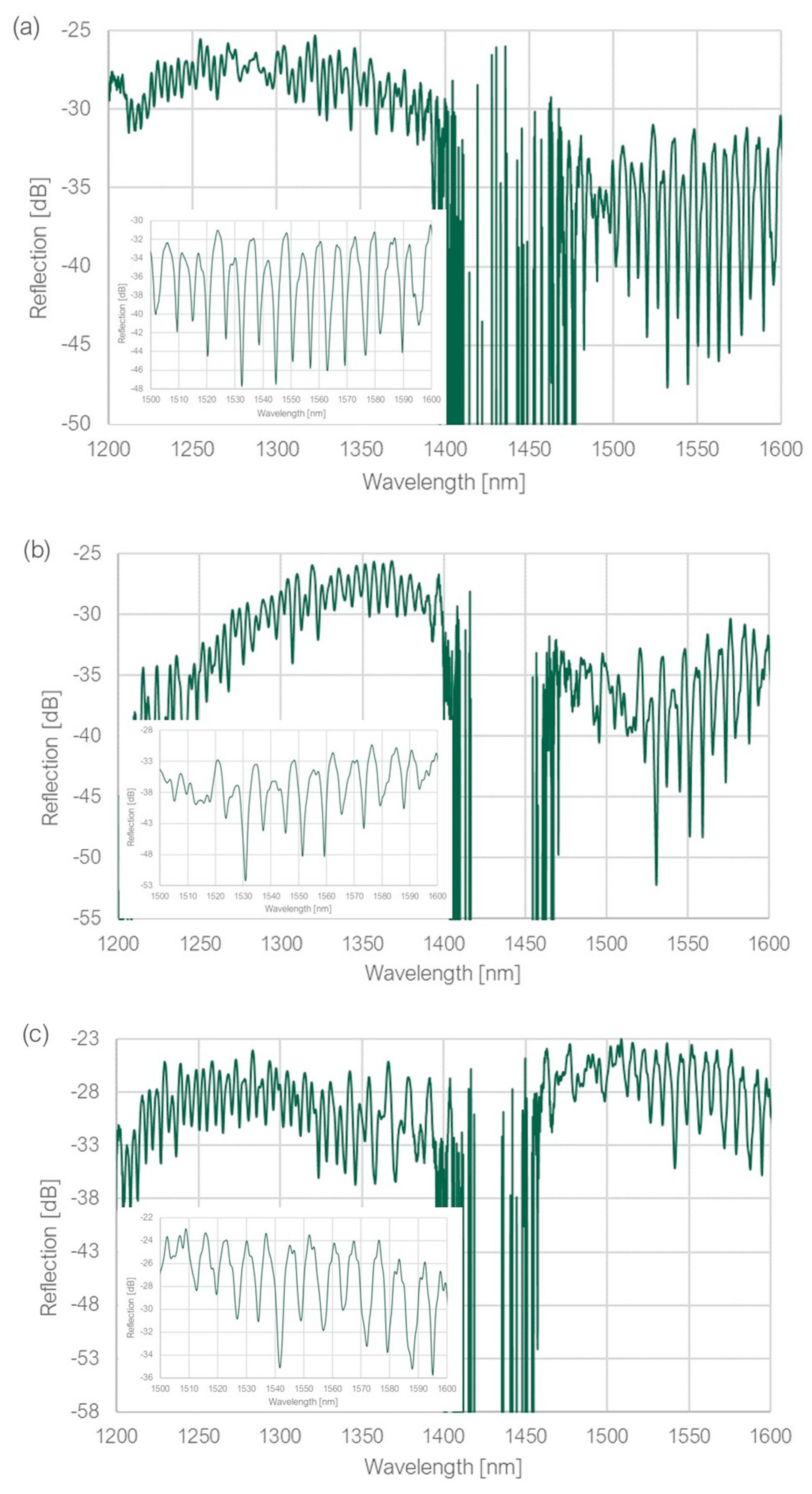
Figure 3), the light was introduced by two SLD sources of central operating wavelengths equal to 1310 nm and 1550 nm. The source signals were transmitted to an optical combiner, where they were combined and transmitted to Port 1 of optical circulator. The tested sample was connected to Port 2, the light after reflecting was traveling back to Port 2, then directly to Port 3 and to an Optical Spectrum Analyzer (Yokogawa AQ 6370C). All elements were connected with standard single-mode patch cords. The measured spectra in the whole wavelength range are shown in
Figure 4, the attached insets give a better look at the region of the best extinction ratio.
All measured structures were capable of exciting resonant modes of a high extinction ratio, particularly in the wavelength range of 1500 – 1600 nm, reaching 16 dB, 18 dB and 11 dB for the structure of ring diameter equal to 40 μm, 34 μm and 28 μm, respectively. However, it was noticed that the measured FSR values were not in agreement with the calculated theoretical values. It was identified, that the observed dips could have their source somewhere else than inside the ring. The path of the uncoupled light (look at
Figure 1), consisting of the coupling waveguide (the base and two tapered arms), together with part of the ring, created a closed loop, along which the light could resonate if the resonance condition from Equation 1 was fulfilled. The calculated FSR values for both paths (along the ring and the “loop”) were compared to the measured values, as shown in
Table 1.
An effort was made to increase the amount of light coupled to the ring. Several numerical simulations were conducted, which provided an insight into the light behavior inside the structure. The Ansys Lumerical FDTD solver was used to simulate the area of waveguide-ring transition and the ring itself. The simulations were performed for the ring diameter of 16 μm – it was reduced to restrain the simulation time.
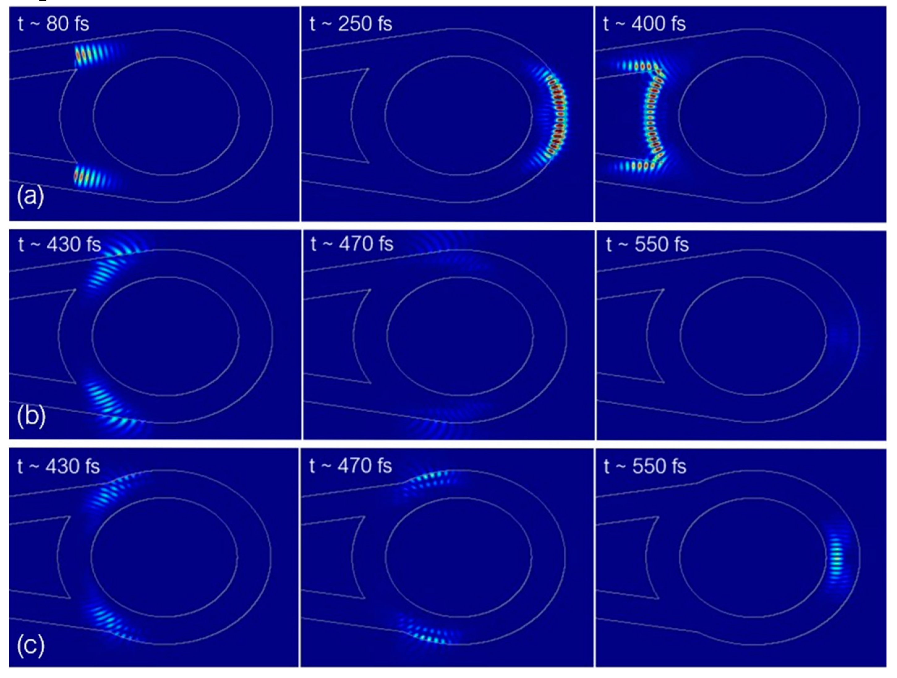
Figure 5(a) illustrates how a beam with the spectral range of around 1500 – 1600 nm behaves in time of the first roundtrip in the ring and
Figure 5(b) illustrates what happens after it. The beams, instead of continuing to propagate along the rim of the ring, encountered a flat surface and the angle of incidence no longer supported the total internal reflection, what resulted in the leakage. The proposed solution was to move the tapers in a way to no longer create this flat segment on sides of the ring. The tapers were moved closer together by a distance equal to 0.4 radians along the ring. The propagation in the second roundtrip after applying this modification is shown in
Figure 5(c).
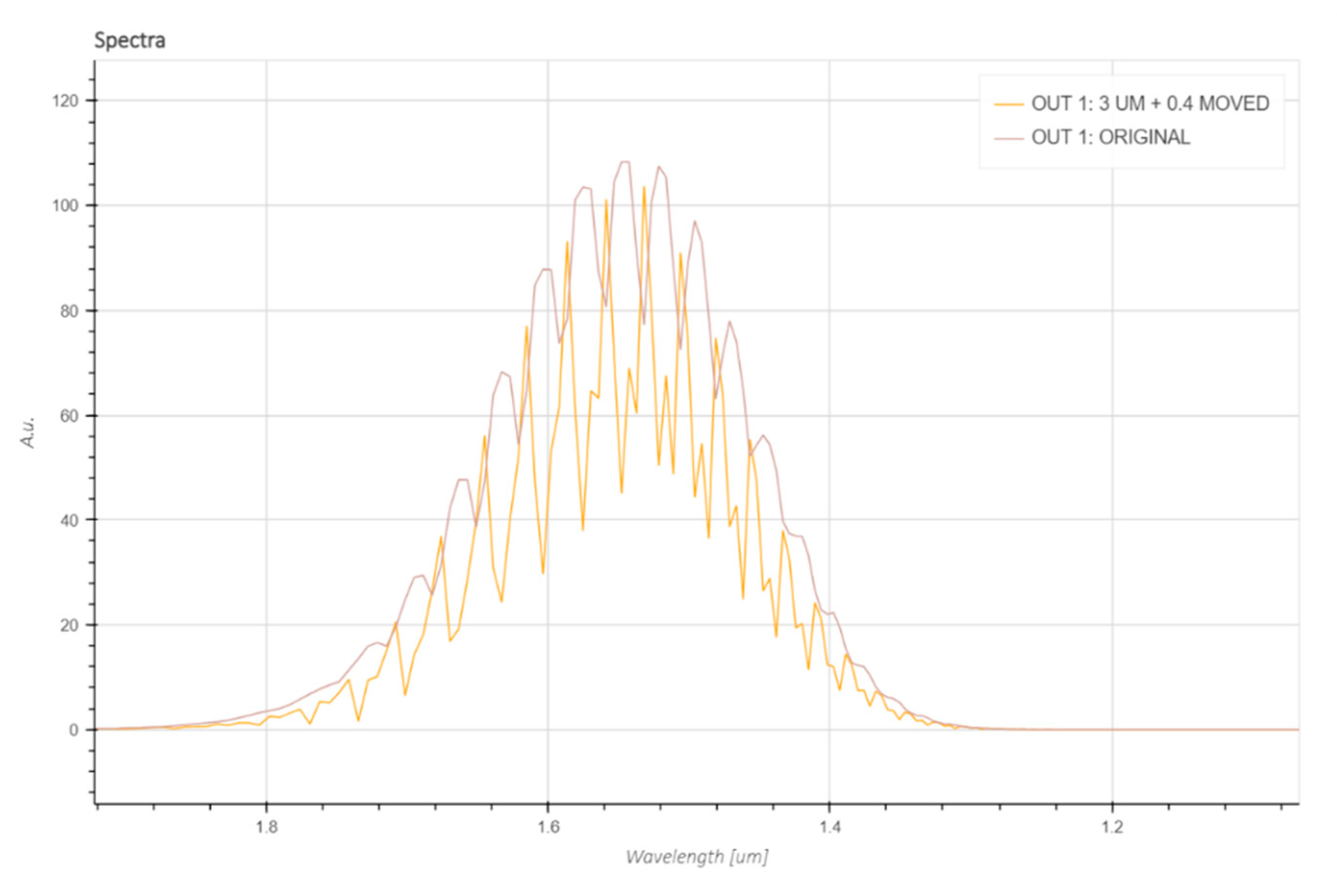
It can be noticed that the intensity of the remaining light in the second roundtrip is much higher than previously, but for more precise comparison, the fields were measured with a “Time” monitor, which gives information about the field in wavelength function for a particular point or plane in the simulation region.
Figure 6 illustrates the comparison between the obtained output fields.
The obtained from simulations spectra show that the extinction ratio increased after moving the tapers, meaning more light stayed in the ring in a form of WGMs. The FSR of the modes was equal to ~ 30 nm in the wavelength region of ~ 1.55 μm. This FSR value is in agreement with the result obtained with Equation 2.
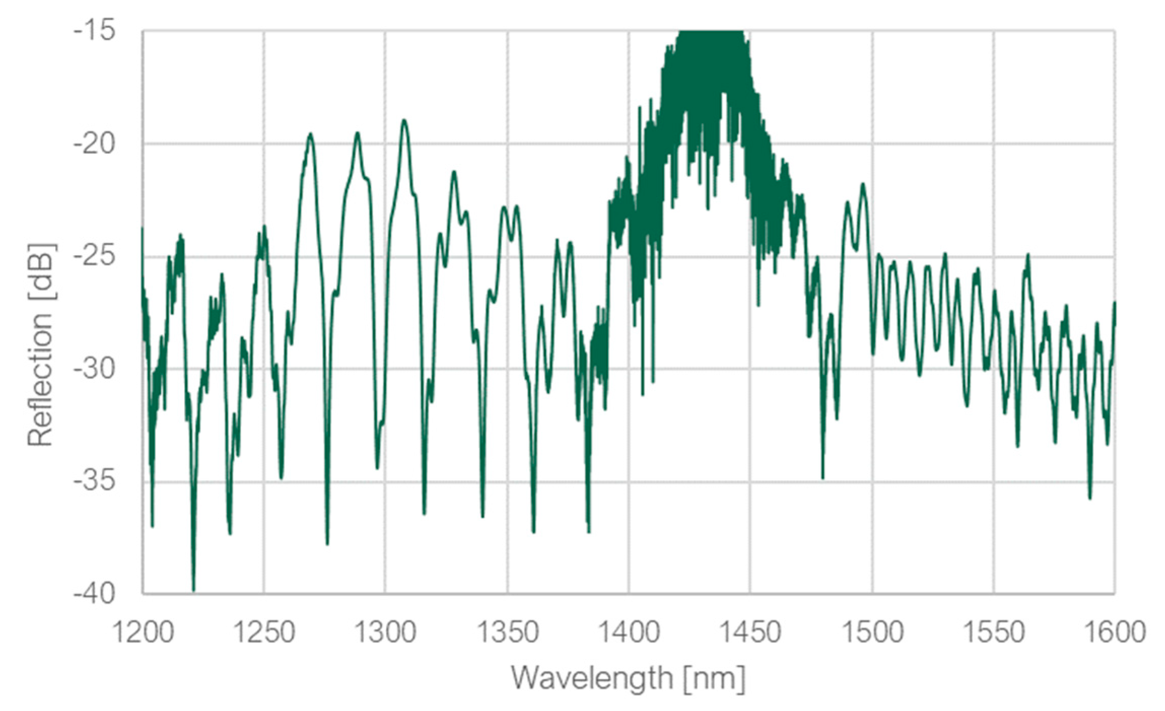
The simulated structure was printed to observe if the simulations can be translated into reality. The ring diameter of 16 μm was maintained, but the distance between the ring and the fiber facet was increased slightly, to increase the taper length, which is reduced each time when the ring diameter is reduced (the tangential is lower). It is important to keep the taper long enough, because if the taper is too short, the power loss on it can be high. The spectrum measured in the optical setup is shown in
Figure 7.
Dips with high extinction ratio of around 18 dB with much wider FSR can be observed in spectral range around 1310 nm, so several FSRs in this range were measured and compared to theoretical values for both ring and loop to determine their source. The comparison is demonstrated in
Table 2.
Basing on the results presented in
Table 2, it may be concluded that the deep dips in the wavelength range around 1310 nm are the result of resonance inside the ring. However, the resonance spectrum in this range is not uniform - narrower resonance modes can be observed inside the ones with FSR equal to ~ 20 nm. These modes can be the result of resonance along the loop. If it comes to the modes in the wavelength range around 1550 nm, it is difficult to distinguish if they are the result of the resonance along the loop or the combination of both resonance spectra.
After these measurements, another adjustment of the structure was proposed with intention to generate both ring and loop resonances. Having two resonance spectra intersecting each other is often desired for reference between one and another to eliminate measurement deviations due to e.g., temperature. Such procedure is being done with use of two WGM resonators of a different diameter [
18] or using two different resonator types [
19].
The concept was to decrease the thickness of the ring to 1 μm, instead of relocating the tapers. If the thickness is reduced, the incidence angle after a roundtrip, which previously caused the leakage, can still be altered in the desired way. At the same time, thanks to not moving the tapers but keeping them at the tangential of the ring, the loop resonance could potentially be observed again. The diameter of the ring was left to be 16 μm. The printed structure is depicted in
Figure 8, together with the measured spectrum. Due to the low thickness of the ring, the structure was printed together with a protective cavity.
In the wavelength range around 1310 nm, the ring dips are much deeper than the loop dips, but in the range around 1550 nm, they have a comparable depth. Nevertheless, both resonances can be clearly distinguished. The FSRs were once again measured and compared to the theoretical values, what is presented in
Table 3 and
Table 4. The extinction ratio is much lower than in the previous structure, but the reason of it may be that the printed structure is slightly tilted.
3.2. Measurements with varying ambient refractive index
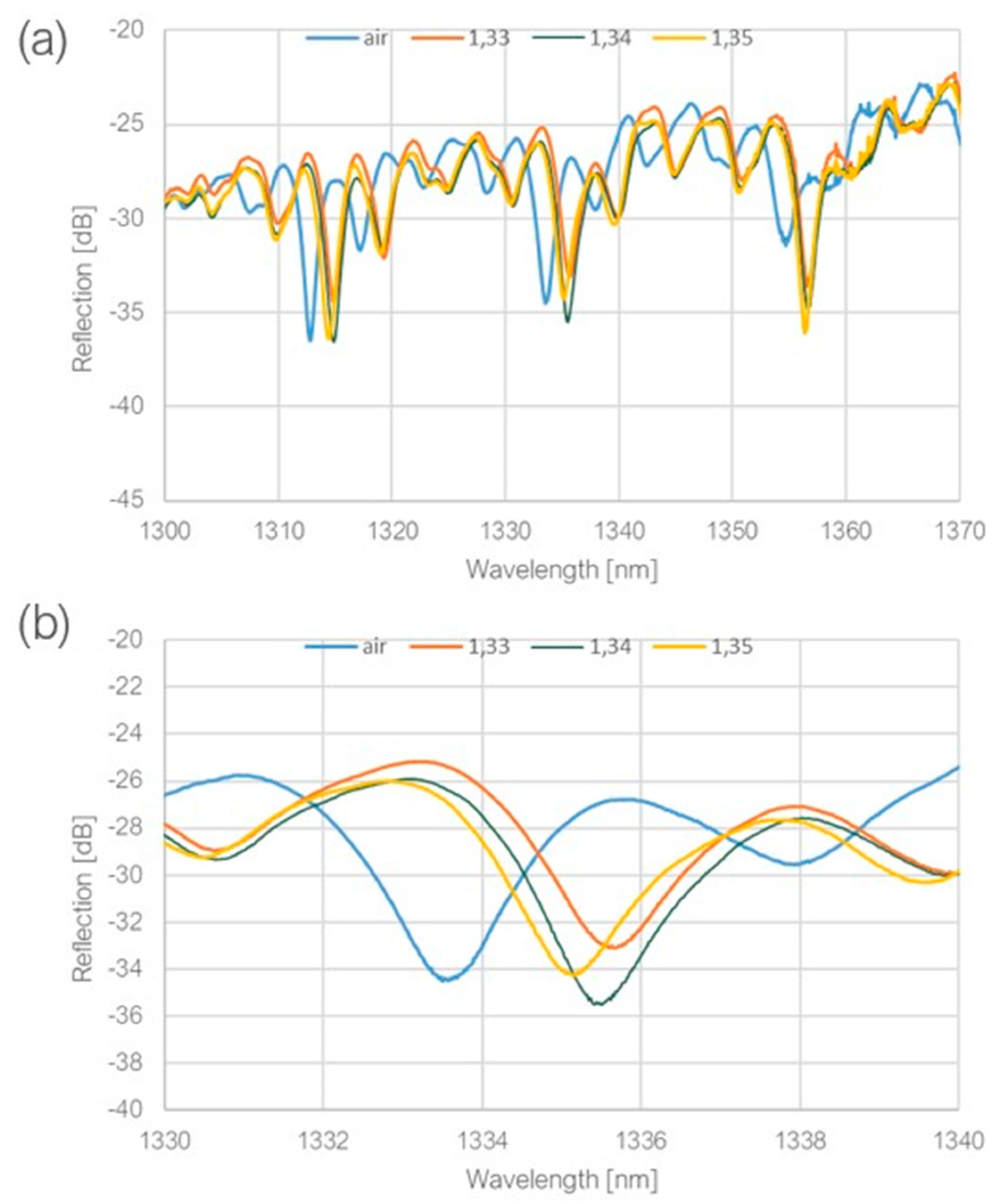
For the RI measurements, a set of liquid solutions was prepared with RI (n
D)values of 1.33, 1.34 and 1.35. The measured spectra are shown in
Figure 9.
After immersion in the liquids, the extinction ratio increased slightly and was equal to around 8 dB, so the resonance dips could be easily discernible, as well as the resonance wavelength shift when the ambient RI was increasing. However, the sensitivity in this RI range was calculated to be rather low, standing at only 25 nm/RIU. Regarding the dip shift between the measurement in the air and in RI equal to 1.33, which amounted to 20.80 nm, the sensitivity within the RI range of 1 – 1.33 can be estimated at a somewhat more favorable rate of 63 nm/RIU. The Q-factor was measured to be above 1000.
4. Discussion and conclusions
The proposed structure shows a great potential for refractive index sensing. A resonance spectrum was successfully achieved with a quite high extinction ratio of the resonance dips (around 8 dB after immersion in RI ~ 1.33) and a quite high Q-factor (above 1000). Two intersecting resonance spectra constitute the output signal, what can be used for self-referencing and eliminating temperature influence on the measurements. The outstanding advantage of the proposed sensor, when compared to other propositions presented in the literature so far, is its simplicity, ease and short time of fabrication and integration with a single tip of a single-core fiber. The measured sensitivity was rather low, what requires further improvements. The Lumerical software provides a possibility of simulating different RIs of the surrounding medium, so simulations of sensor’s behavior after immersion can be performed in future to search for geometrical adjustments, which would improve the sensitivity. One of the possible adjustments is simply increasing the ring diameter – longer distance of the sensing region means more interaction with the ambient medium.
Another, particularly interesting proposition is coating the structure with noble metals to excite Surface Plasmon Polaritons, causing light enhancement and increasing its confinement at the structure surface. In general, in WGM resonators with no coating applied, relatively small amount of light propagates outside of the resonator boundaries and the usually achieved sensitivities are around 100 nm/RIU. Several research have shown that coating with noble metals can increase the sensitivity of such structures significantly [
20], but this procedure introduces a significant problem in structures coupled via evanescent wave coupling - the thicker layer of the material, the larger attenuation of the field during coupling, the less energy enters the resonator. The proposed in this research structure would have a particular advantage in this matter, as it utilizes direct waveguide coupling.
| WGM |
Whispering gallery modes |
| 2PP |
Two-Photon Polymerization |
| RI |
Refractive Index |
| RIU |
Refractive Index Unit |
| Q-factor |
Quality factor |
| FDTD |
Finite Difference Time Domain |
Author Contributions
Conceptualization, M.H. and S.E.; methodology, M.H. and S.E.; numerical simualtions, M.H.; interpretation and validation, MH, SE., sample preparation, measurements and data analysis: MH (with direct supervision of SE); writing—original draft preparation, MH; writing—review and editing, SE, MH.;. All authors have read and agreed to the published version of the manuscript.
Institutional Review Board Statement
Not applicable.
Informed Consent Statement
Not applicable.
Data Availability Statement
The data presented in this study are available on request from the authors.
Acknowledgments
The research were carried out on devices co-funded by the Warsaw University of Technology within the Excellence Initiative: Research University (IDUB) program.
Conflicts of Interest
The authors declare no conflict of interest.
Abbreviations:
The following abbreviations are used in this manuscript:
References
- Cai, L.; Pan, J.; Hu, S. Overview of the coupling methods used in whispering gallery mode resonator systems for sensing. Opt. Lasers Eng. 2019, 127, 105968. [Google Scholar] [CrossRef]
- Loyez, M.; Adolphson, M.; Liao, J.; Yang, L. From Whispering Gallery Mode Resonators to Biochemical Sensors. ACS Sensors 2023, 8, 2440–2470. [Google Scholar] [CrossRef] [PubMed]
- Brooks, A.; Chu, X.-L.; Liu, Z.; Schott, R.; Ludwig, A.; Wieck, A.D.; Midolo, L.; Lodahl, P.; Rotenberg, N. Integrated Whispering-Gallery-Mode Resonator for Solid-State Coherent Quantum Photonics. Nano Lett. 2021, 21, 8707–8714. [Google Scholar] [CrossRef] [PubMed]
- Chen, Y.; Yin, Y.; Ma, L.; Schmidt, O.G. Recent Progress on Optoplasmonic Whispering-Gallery-Mode Microcavities. Adv. Opt. Mater. 2021, 9, 2100143. [Google Scholar] [CrossRef]
- Foreman, M.R.; Swaim, J.D.; Vollmer, F. Whispering gallery mode sensors. Adv. Opt. Photon- 2015, 7, 168–240. [Google Scholar] [CrossRef] [PubMed]
- Wang, M.; Zhao, J.; Wang, X.; Chen, J.; Zhao, Y.; Zhang, Y.-N. Large measurement range temperature sensor based on WGM and MMI in an offset structure fiber coupler. Opt. Fiber Technol. 2023, 80. [Google Scholar] [CrossRef]
- Geints, Y.; Minin, O.; Minin, I. Proof-of-concept of a miniature pressure sensor based on coupled optical WGMs excited in a dielectric microsphere. Opt. Laser Technol. 2022, 151. [Google Scholar] [CrossRef]
- Vollmer, F.; Arnold, S.; Keng, D. Single virus detection from the reactive shift of a whispering-gallery mode. Proc. Natl. Acad. Sci. 2008, 105, 20701–20704. [Google Scholar] [CrossRef] [PubMed]
- Chiang, C.-C.; Chao, J.-C. Whispering Gallery Mode Based Optical Fiber Sensor for Measuring Concentration of Salt Solution. J. Nanomater. 2013, 2013, 1–4. [Google Scholar] [CrossRef]
- Nanjunda, S.B.; Seshadri, V.N.; Krishnan, C.; Rath, S.; Arunagiri, S.; Bao, Q.; Helmerson, K.; Zhang, H.; Jain, R.; Sundarrajan, A.; et al. Emerging nanophotonic biosensor technologies for virus detection. Nanophotonics 2022, 11, 5041–5059. [Google Scholar] [CrossRef]
- Shangguan, Q.; Chen, Z.; Yang, H.; Cheng, S.; Yang, W.; Yi, Z.; Wu, X.; Wang, S.; Yi, Y.; Wu, P. Design of Ultra-Narrow Band Graphene Refractive Index Sensor. Sensors 2022, 22, 6483. [Google Scholar] [CrossRef] [PubMed]
- Wei, H.; Krishnaswamy, S. Polymer micro-ring resonator integrated with a fiber ring laser for ultrasound detection. Opt. Lett. 2017, 42, 2655–2658. [Google Scholar] [CrossRef] [PubMed]
- Shi, L.; Zhu, T.; Huang, D.; Liu, M.; Deng, M.; Huang, W. In-fiber whispering-gallery-mode resonator fabricated by femtosecond laser micromachining. Opt. Lett. 2015, 40, 3770–3773. [Google Scholar] [CrossRef] [PubMed]
- Zhang, Y.-N.; Zhu, N.; Zhou, T.; Zheng, Y.; Shum, P.P. Research on Fabrication and Sensing Properties of Fiber-Coupled Whispering Gallery Mode Microsphere Resonator. IEEE Sensors J. 2019, 20, 833–841. [Google Scholar] [CrossRef]
- Wei, H.; Krishnaswamy, S. Direct Laser Writing Polymer Micro-Resonators for Refractive Index Sensors. IEEE Photon- Technol. Lett. 2016, 28, 2819–2822. [Google Scholar] [CrossRef]
- Zhang, S.; Tang, S.; Feng, S.; Xiao, Y.; Cui, W.; Wang, X.; Sun, W.; Ye, J.; Han, P.; Zhang, X.; et al. High-Q Polymer Microcavities Integrated on a Multicore Fiber Facet for Vapor Sensing. Adv. Opt. Mater. 2019, 7, 1900602. [Google Scholar] [CrossRef]
- Otuka, A.J.G.; Tomazio, N.B.; Paula, K.T.; Mendonça, C.R. Two-Photon Polymerization: Functionalized Microstructures, Micro-Resonators, and Bio-Scaffolds. Polymers 2021, 13, 1994. [Google Scholar] [CrossRef] [PubMed]
- Li, H.; Zhang, H.; Sun, J.; Yu, M.; Zhang, Z.; Ge, Y. Whispering gallery mode splitting on filling-based microresonators for refractive index sensing. Opt. Commun. 2021, 497, 127193. [Google Scholar] [CrossRef]
- Lu, C.; Nikbakht, H.; Karabiyik, M.; Alaydrus, M.; Akca, B.I. A compound optical microresonator design for self-referencing and multiplexed refractive index sensing. Opt. Express 2021, 29, 42215–42224. [Google Scholar] [CrossRef]
- Yin, Y.; Nie, T.; Ding, M. Refractive Index Sensor Based on Gold-Coated Whispering Gallery Mode Microdisk Resonator. IEEE Sensors J. 2020, 20, 9871–9876. [Google Scholar] [CrossRef]
|
Disclaimer/Publisher’s Note: The statements, opinions and data contained in all publications are solely those of the individual author(s) and contributor(s) and not of MDPI and/or the editor(s). MDPI and/or the editor(s) disclaim responsibility for any injury to people or property resulting from any ideas, methods, instructions or products referred to in the content. |
© 2023 by the authors. Licensee MDPI, Basel, Switzerland. This article is an open access article distributed under the terms and conditions of the Creative Commons Attribution (CC BY) license (https://creativecommons.org/licenses/by/4.0/).


