1. Introduction
The rapid evolution of wireless communication technologies has enabled ubiquitous connectivity, transforming our lifestyles and work practices [
1]. This progress has resulted in a wide range of applications, ranging from mobile networks and IoT devices to smart cities and augmented reality [
2]. The base station antenna is a pivotal element in this revolution, ensuring reliable and efficient communication services to handle the exponential growth of data traffic [
3,
4]. As demand grows, the emphasis shifts to developing high-performance antennas, particularly for mobile networks, in order to meet the requirements of modern applications [
4].
Antennas are vital components of wireless communication systems because they enable the transmission and reception of electromagnetic waves [
5]. Their design parameters include bandwidth, polarization, impedance, radiation patterns, gain, and efficiency [
6].
There are several types of antennas, including patch, slot, monopole, dipole, horn, and Yagi-Uda antennas [
7]. Slot antennas, like patch antennas, consist of flat metal plates with slots that allow electromagnetic wave radiation [
8]. They are simple and tunable for better performance by adjusting slot size and cavity design. However, slot antennas have low radiation efficiency and higher cross-polarization levels, which can be improved by reducing substrate thickness [
9].
Circularly polarized (CP) antennas are popular for mobile communications because they allow for flexible orientation of the transmitting and reception antennas, improved mobility, and reduced multipath fading caused by reflections and obstructions [
10,
11]. To generate CP radiation, two orthogonal modes should be excited simultaneously with equal amplitude and 90° phase difference [
12,
13].
The objective of this paper is to present the design and analysis of a circularly polarized broadband slot antenna specifically tailored for base station mobile applications. The proposed antenna aims to address the limitations of traditional narrowband antennas by offering a wide bandwidth while maintaining excellent radiation characteristics. The design incorporates innovative techniques and optimization algorithms to achieve a compact and efficient antenna structure. To achieve the desired performance, the design process involves a comprehensive analysis of the antenna’s electromagnetic characteristics, including impedance matching, radiation pattern, and gain. Advanced simulation tools and numerical methods are employed to optimize the antenna’s parameters and ensure its compliance with the stringent requirements of base station applications.
2. Antenna Design
2.1. Antenna Configuration
The HFSS-designed antenna, which employs an offset microstrip line feeding technique, is a slot antenna with a compositely shaped patch made up of a rectangle with two rectangular and crescent-shaped stubs.
The ground plan has a wide slot that has been geometrically modified, and a smaller circular slot is added later to improve the antenna’s broadband and circular polarization characteristics.
2.2. Antenna Geometry
The antenna, simulated using Ansys High-Frequency Structure Simulator (HFSS), utilizes a square-shaped FR4 Epoxy substrate as the ground and a copper-coated patch.
The substrate’s relative permittivity (𝜀r) is 4.4, and its dielectric loss tangent (δ) is 0.02. With length of 60mm, and a height of 1mm, the square substrate measures 60×60×1 mm³ in total size.
3. Design Procedure
3.1. Antenna without Slot
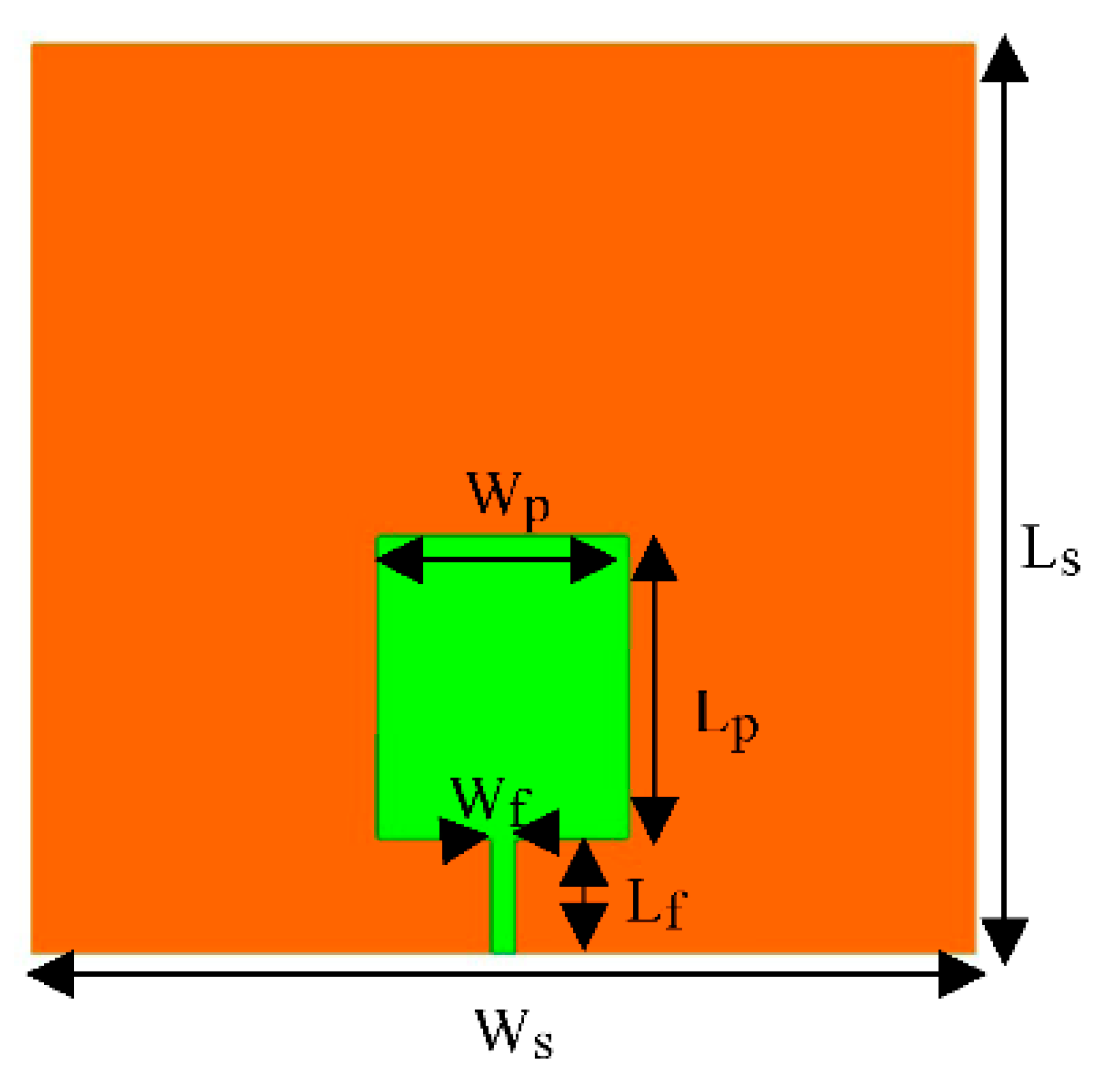
The antenna without a slot is illustrated in
Figure 1. The green color indicates the patch, while the orange color represents the ground visible through the 1mm FR4 Epoxy substrate. The substrate is 60mm in length, square-shaped, and coated with copper on both sides. The antenna’s feeding mechanism consists of a 7.5mm long, 1.5mm wide microstrip feedline placed on top of the substrate. A rectangular copper-coated patch (20mm x 16mm) starts where the feedline ends and is merged with the feedline using the unite function in HFSS. A lumped port is attached at the end of the feedline.
Table 1.
HFSS. A lumped port is attached without slot.
Table 1.
HFSS. A lumped port is attached without slot.
| Parameter |
Ls
|
Ws
|
Lp
|
Wp
|
Lf
|
Wf
|
| Value (mm) |
60 |
60 |
20 |
16 |
7.5 |
1.5 |
3.2. Slot Antenna
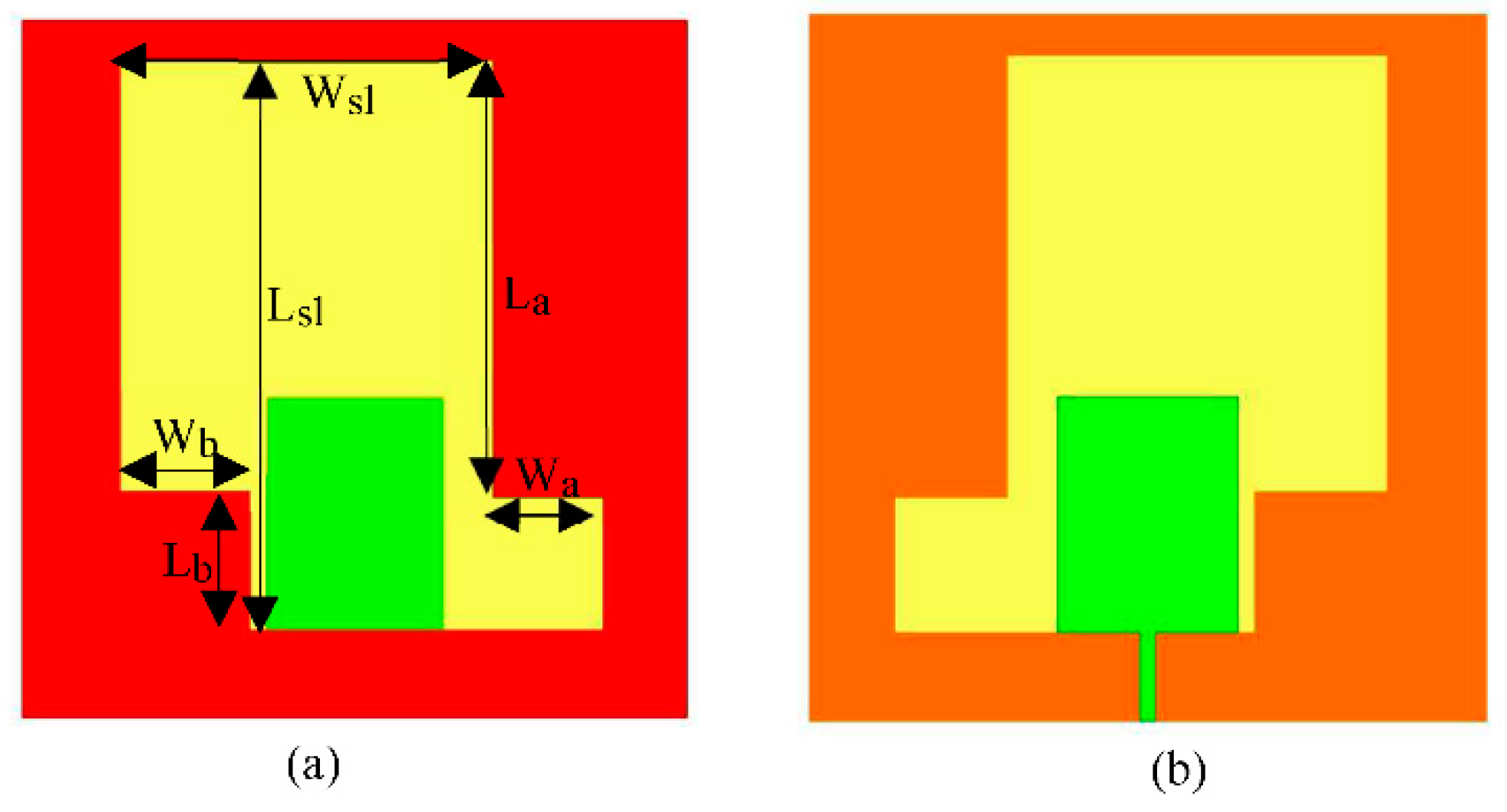
The slot antenna illustrated in
Figure 2. is based on the antenna without a slot. To create the slot, a portion of the ground plane at the bottom of the substrate is etched. The slot has a total length of 49mm and a width of 43.7mm. Additionally, two rectangular stubs are added to the ground: one at the upper right corner (37.5mm × 10mm) and another at the lower left corner (12mm × 11.7mm). These stubs are united to reduce the slot’s size, resulting in a recessed shape.
The introduction of the slot enables circular polarization and significantly improves impedance matching within the antenna’s operating frequency range.
Table 2.
Optimized Parameters for slot antenna.
Table 2.
Optimized Parameters for slot antenna.
| Parameter |
Lsl
|
Wsl
|
La
|
Wa
|
Lb
|
Wb
|
| Value (mm) |
49 |
33.7 |
37.5 |
10 |
12 |
11.7 |
3.3. Slot Antenna with Offset Feeding
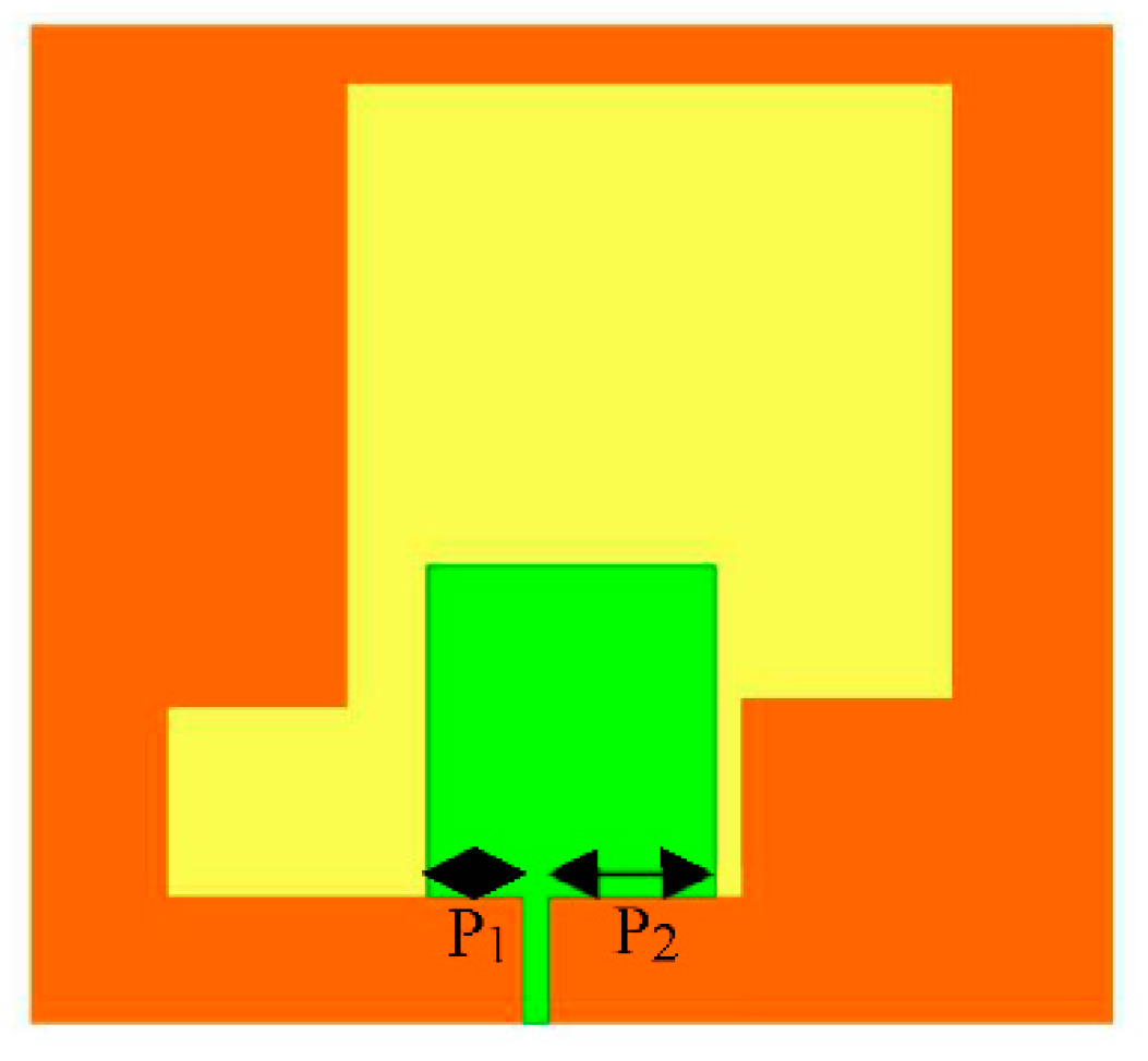
The slot antenna is modified by offsetting the feedline 2mm from the center toward the left with respect to the patch. This modification is visualized in
Figure 3.
Offset feeding improved both the impedance bandwidth and the axial ratio bandwidth.
Table 3.
Optimized Parameters for slot antenna with offset feeding.
Table 3.
Optimized Parameters for slot antenna with offset feeding.
| Parameter |
P1
|
P2
|
| Value (mm) |
5.25 |
9.25 |
3.4. Slot Antenna with One Stub
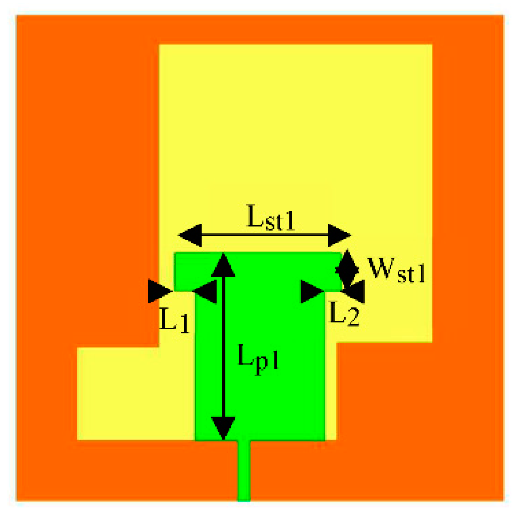
The outlook of the slot antenna with one stub is shown in
Figure 4. It is obtained by adding a rectangular slab to the top of the patch using the unite function. The stub is positioned so it increases the length of the patch by 3.2mm to give the patch a T-shape. The stub is 20.5mm by 5.5mm.
The introduction of this stub increases the Impedance bandwidth of the antenna, allowing for broadband characteristics to be realized.
Table 4.
Optimized parameters for slot antenna with ONE stubs.
Table 4.
Optimized parameters for slot antenna with ONE stubs.
| Parameter |
Lpl
|
Lstl
|
Wstl
|
L1
|
L2
|
| Value (mm) |
23.2 |
20.5 |
5.5 |
2.5 |
2 |
3.5. Slot Antenna with Two Stubs
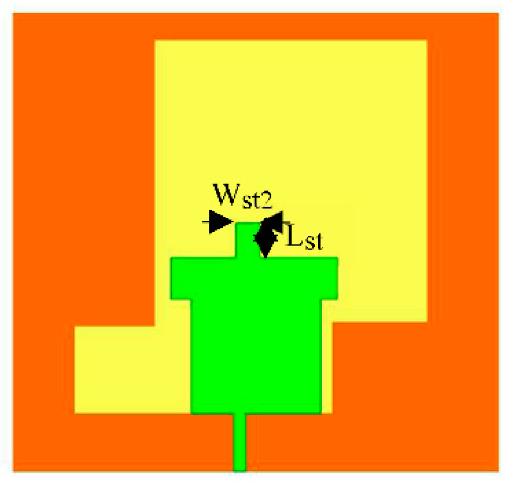
The slot antenna with two stubs is shown in
Figure 5. Another stub is added to the top of the T-shaped patch using the unite function. This stub has a size of 4.5 mm by 3 mm and is centrally placed on the patch. The introduction of this stub improves the impedance matching and greatly enhances the Axial Ratio bandwidth of the antenna, allowing it to be circularly polarized over a greater range of its operating band.
Table 5.
Optimized parameters for slot antenna with two stubs.
Table 5.
Optimized parameters for slot antenna with two stubs.
| Parameter |
Lst2
|
Wst2
|
| Value (mm) |
4.5 |
3 |
3.6. Slot Antenna with Compositely-Shaped Patch
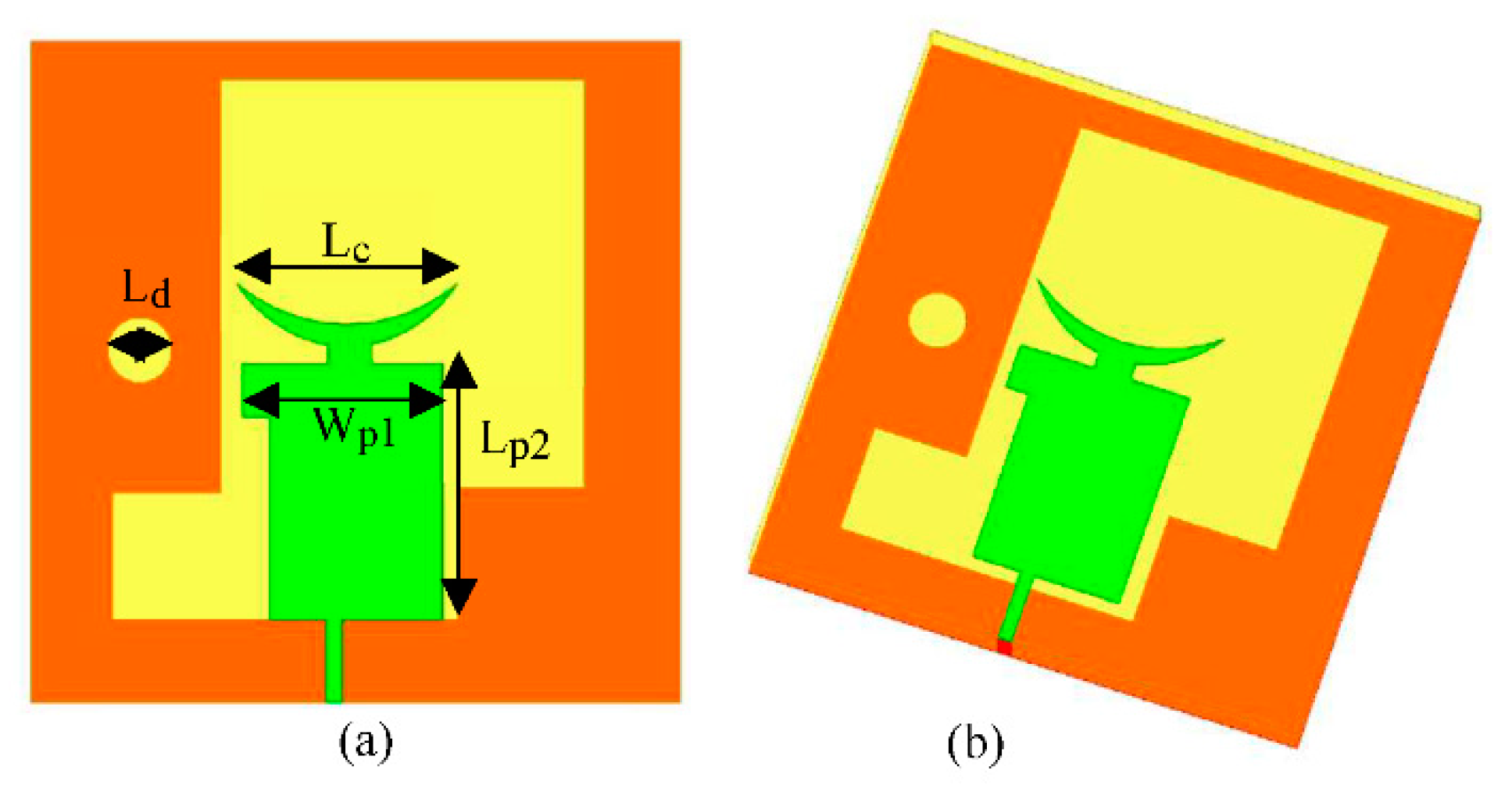
The slot antenna with a compositely-shaped patch is created by modifying the slot antenna with two stubs. In
Figure 6. a crescent-shaped stub is added to the patch. This crescent shape is achieved by subtracting a circle with a radius of 16mm from an ellipse with a major radius of 16mm and a ratio of 0.836. Additionally, a small circular slot with a radius of 3mm is introduced in the ground plane. To refine the design, the first rectangular stub added to the patch is shortened to 18.5mm, no longer protruding at the right side of the patch. Its width is reduced to 4.76mm, and the patch length is increased to 23.25mm, achieving the desired resonating frequency of 1.8 GHz.
Table 6.
Optimized Parameters for slot antenna with compositely-shaped patch.
Table 6.
Optimized Parameters for slot antenna with compositely-shaped patch.
| Parameter |
Lp2
|
Wpl
|
Lc
|
Ld
|
| Value (mm) |
23.25 |
18.5 |
20.48 |
6 |
4. Results and Discussions
4.1. Antenna without Slot
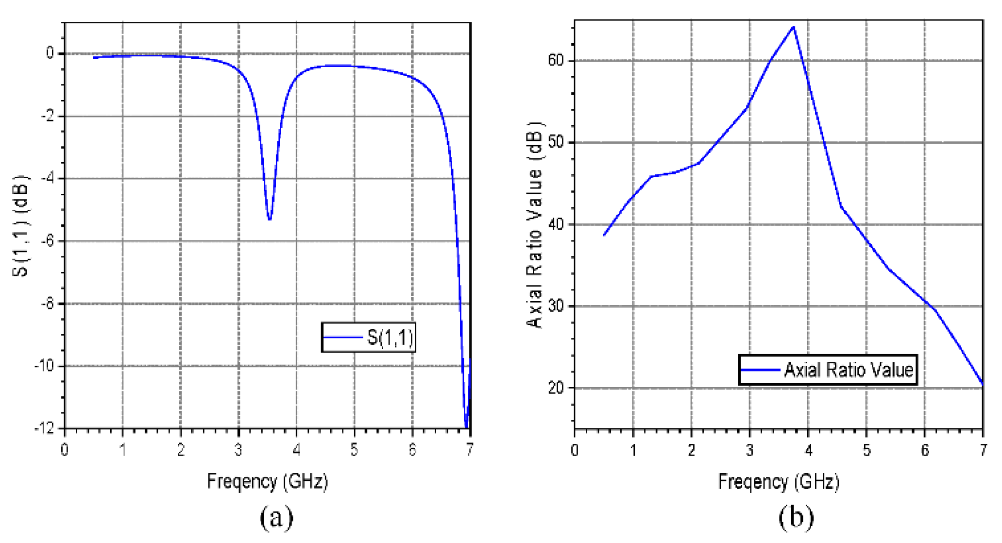
Figure 7 shows the simulated results of the antenna without a slot. The return loss was less than -10 dB at 6.87 GHz to 7.00 GHz, well outside the desired bandwidth. Furthermore, the axial ratio exceeds 44 dB, indicating a lack of circular polarization characteristics. The antenna at this point is unsuitable for the intended design purpose.
4.2. Slot Antenna
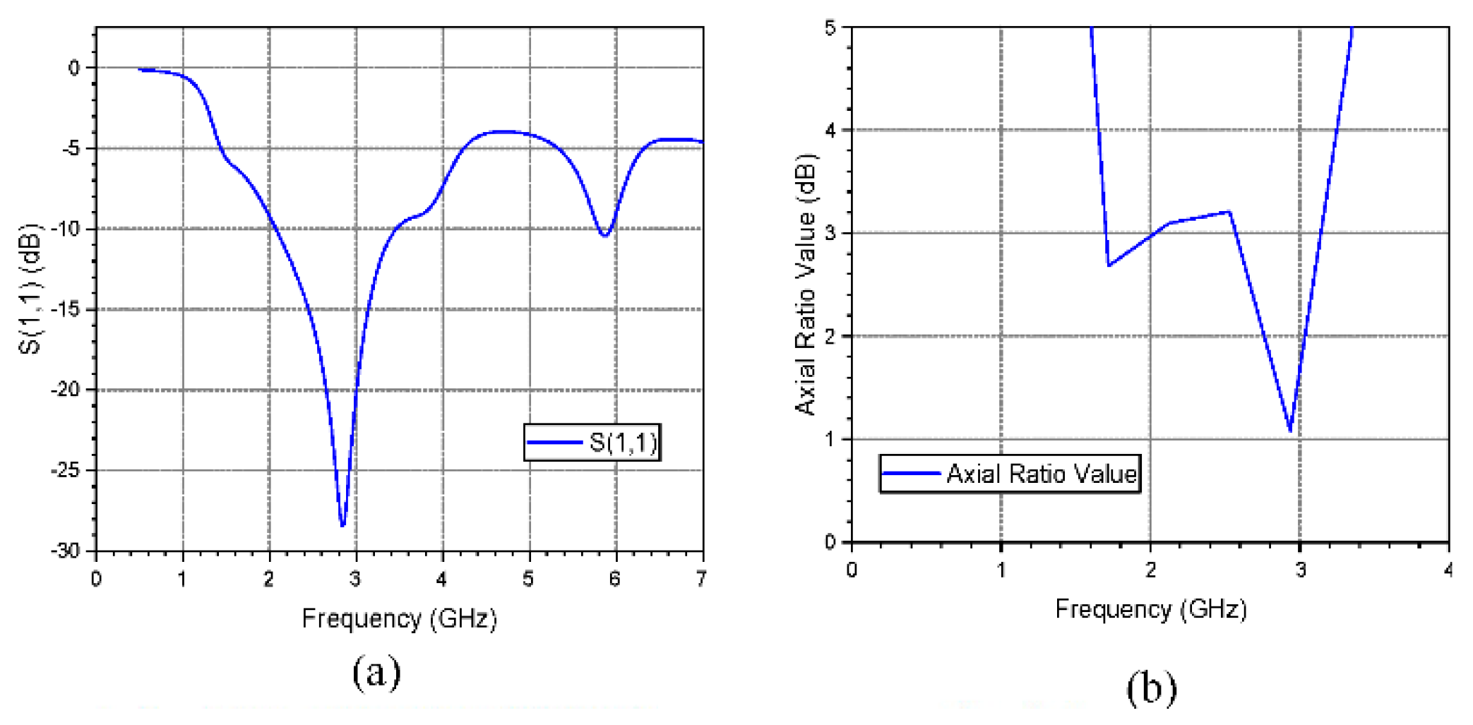
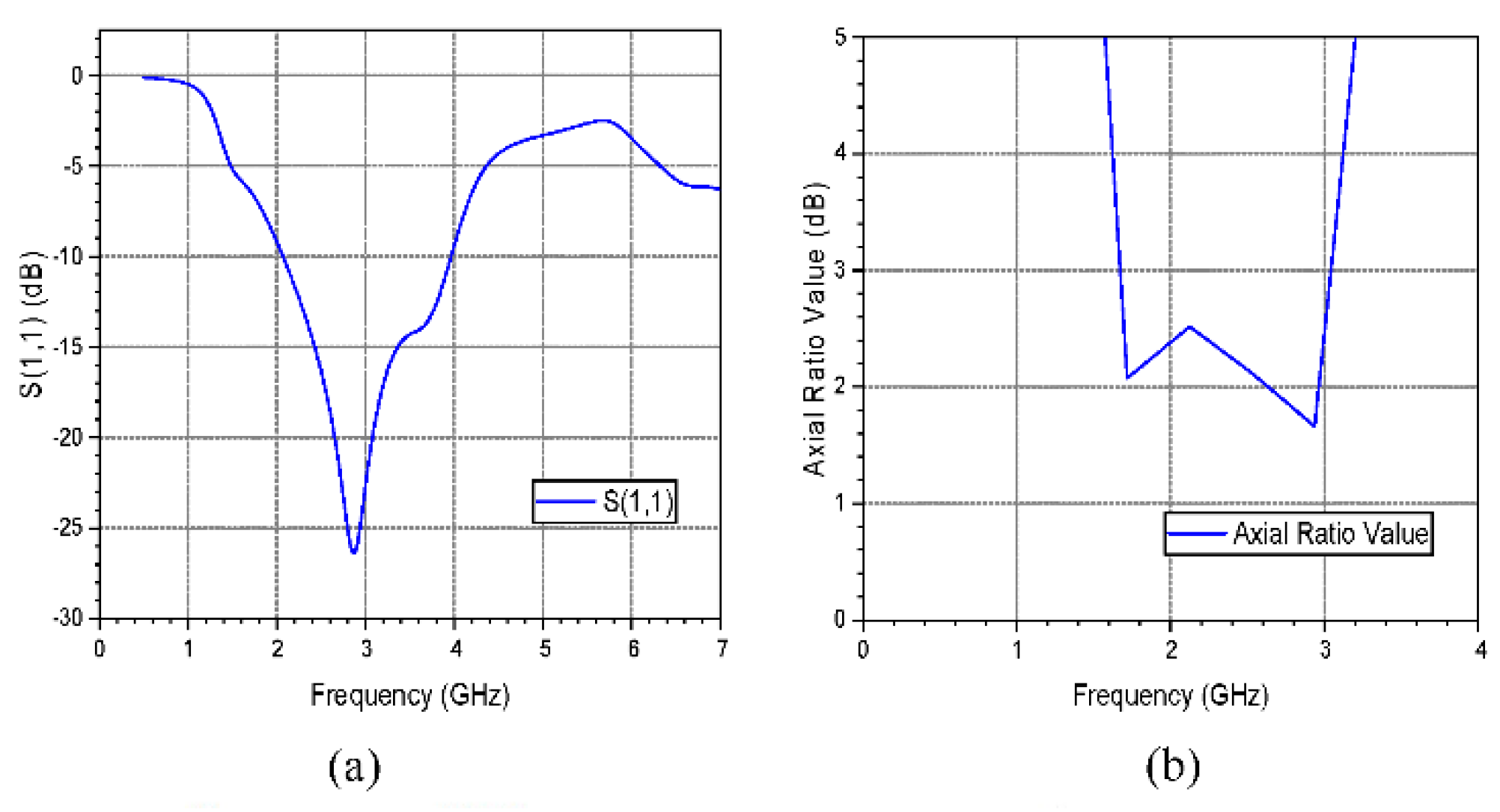
Figure 8 shows the slot antenna simulation results. The Return loss is less than -10dB at 2.07 GHz to 3.46 GHz and 5.80 GHz to 5.93 GHz, indicating good impedance matching in those ranges. The axial ratio value is also less than 3 dB from 1.70 GHz to 2.03 GHz and 2.57 GHz to 3.14 GHz, indicating that the addition of slots introduces circular polarization. The antenna’s resonating frequency, however, is around 2.8 GHz, which does not fit the design purpose.
4.3. Slot Antenna with Offset feeding
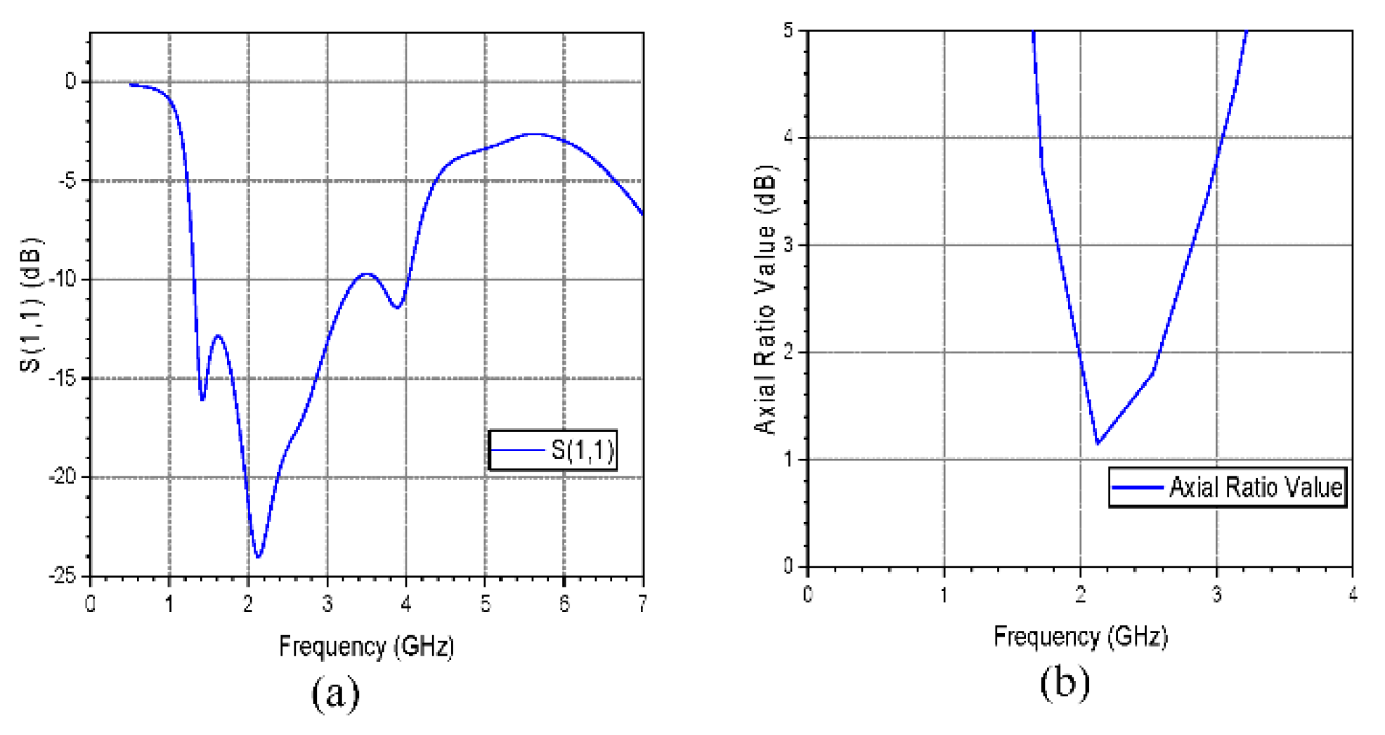
Figure 9 shows the simulated results of the slot antenna with offset feeding. The return loss bandwidth and the axial ratio bandwidth were both increased by offsetting the antenna’s feedline. The return loss bandwidth now spans from 2.07 GHz to 3.97 GHz, while the axial ratio bandwidth is from 1.67 GHz to 3.04 GHz.
4.4. Slot Antenna with One Stub
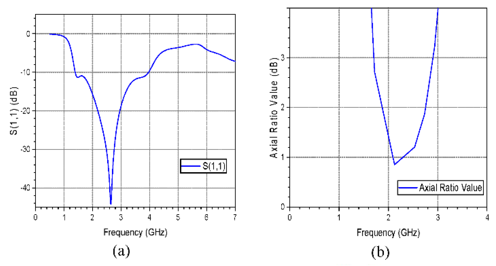
Figure 10 shows the simulated results of the slot antenna with one stub. Adding a stub to the patch slightly increases the return loss bandwidth, which now spans from 1.31 GHz to 3.37 GHz and 3.64 GHz to 4.03 GHz, but not continuously. The resonating frequency was 2.1 GHz. The axial ratio bandwidth, on the other hand, increased from 1.83 GHz to 2.82 GHz.
4.5. Slot Antenna with Two Stubs
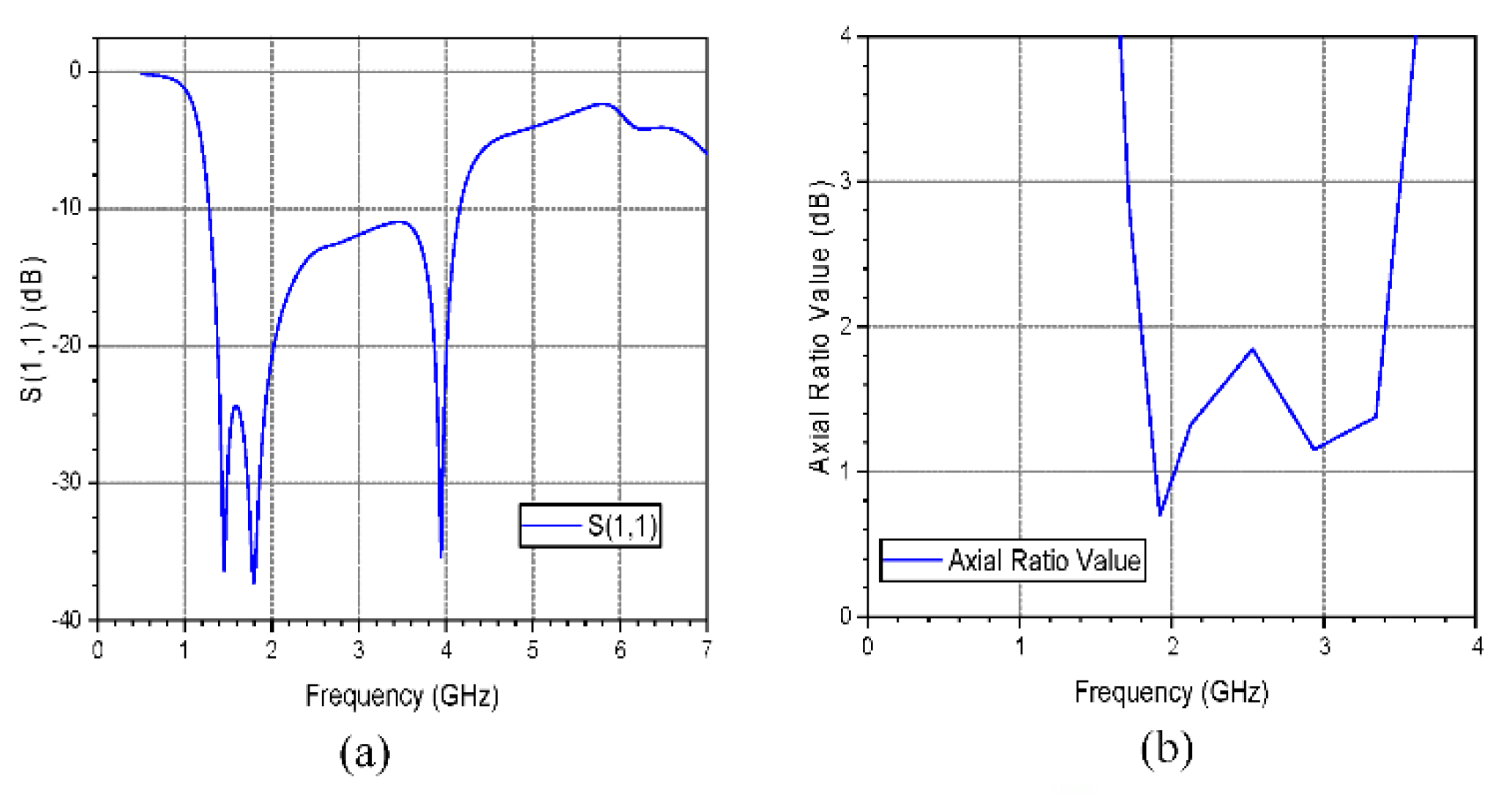
Figure 11 shows the simulated results of the slot antenna with two stubs. The addition of the second stub makes the return loss continuous from 1.39 GHz to 3.96 GHz, but the resonating frequency is shifted away to around 2.65 GHz. The axial ratio bandwidth has been slightly improved and now ranges from 1.70 to 2.90 GHz.
4.6. Slot Antenna with Compositely-Shaped Patch
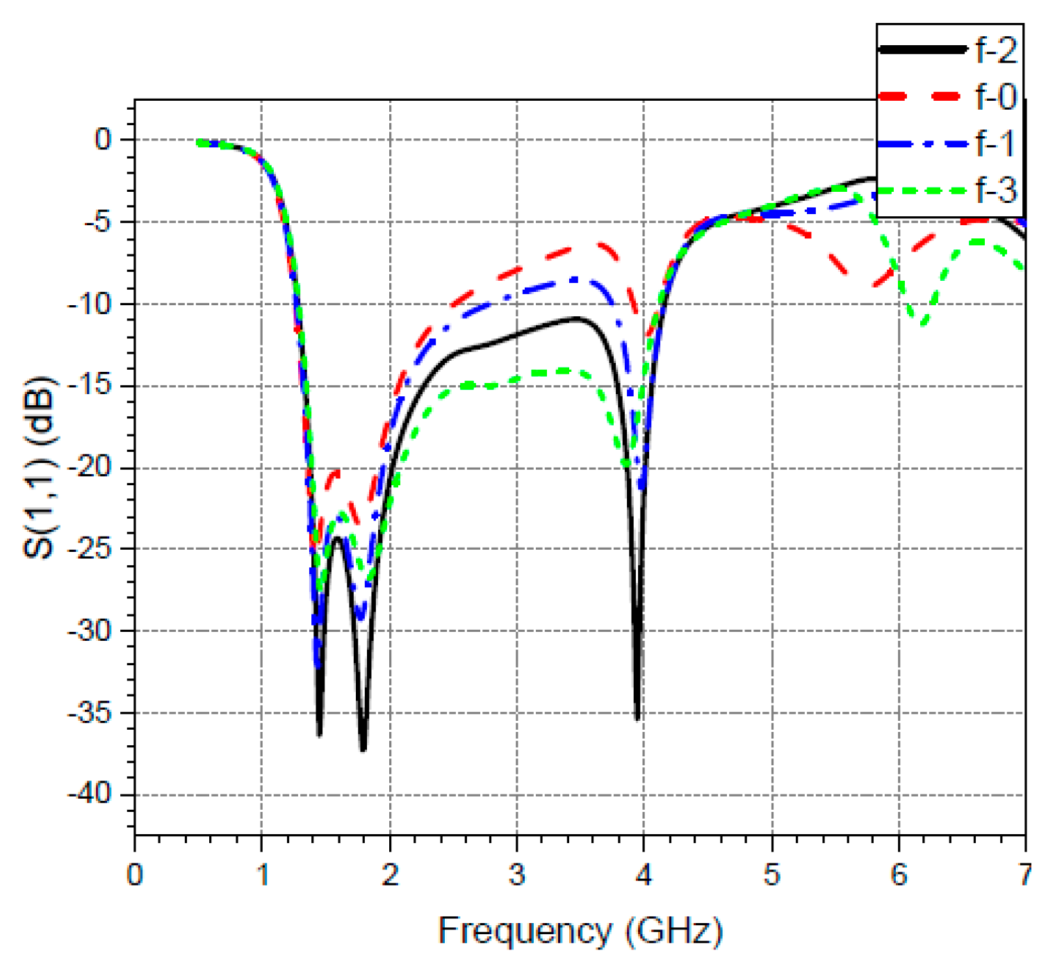
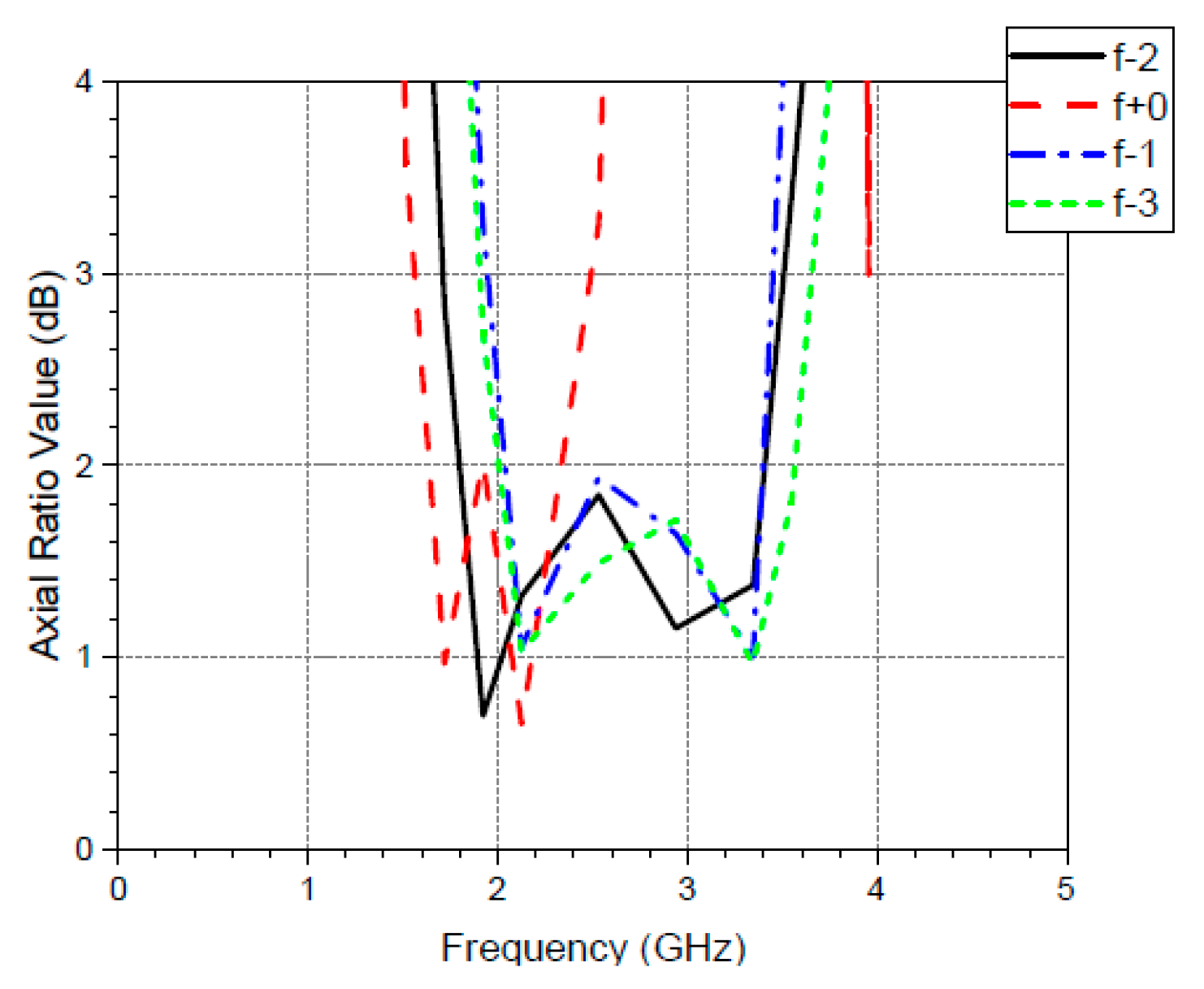
1) S-parameter (S11) and Axial Ratio plot: Figure 12 shows the simulated S-parameter and Axial Ratio results of the slot antenna with compositely-shaped patch. After adding the crescent to the patch and creating a composite shape, the antenna achieves a return loss bandwidth of 1.28 GHz to 4.16 GHz, with the resonating frequency at the desired 1.8 GHz. Additionally, the axial ratio bandwidth significantly increases from 1.71 GHz to 3.51 GHz. This antenna perfectly meets its design requirements.
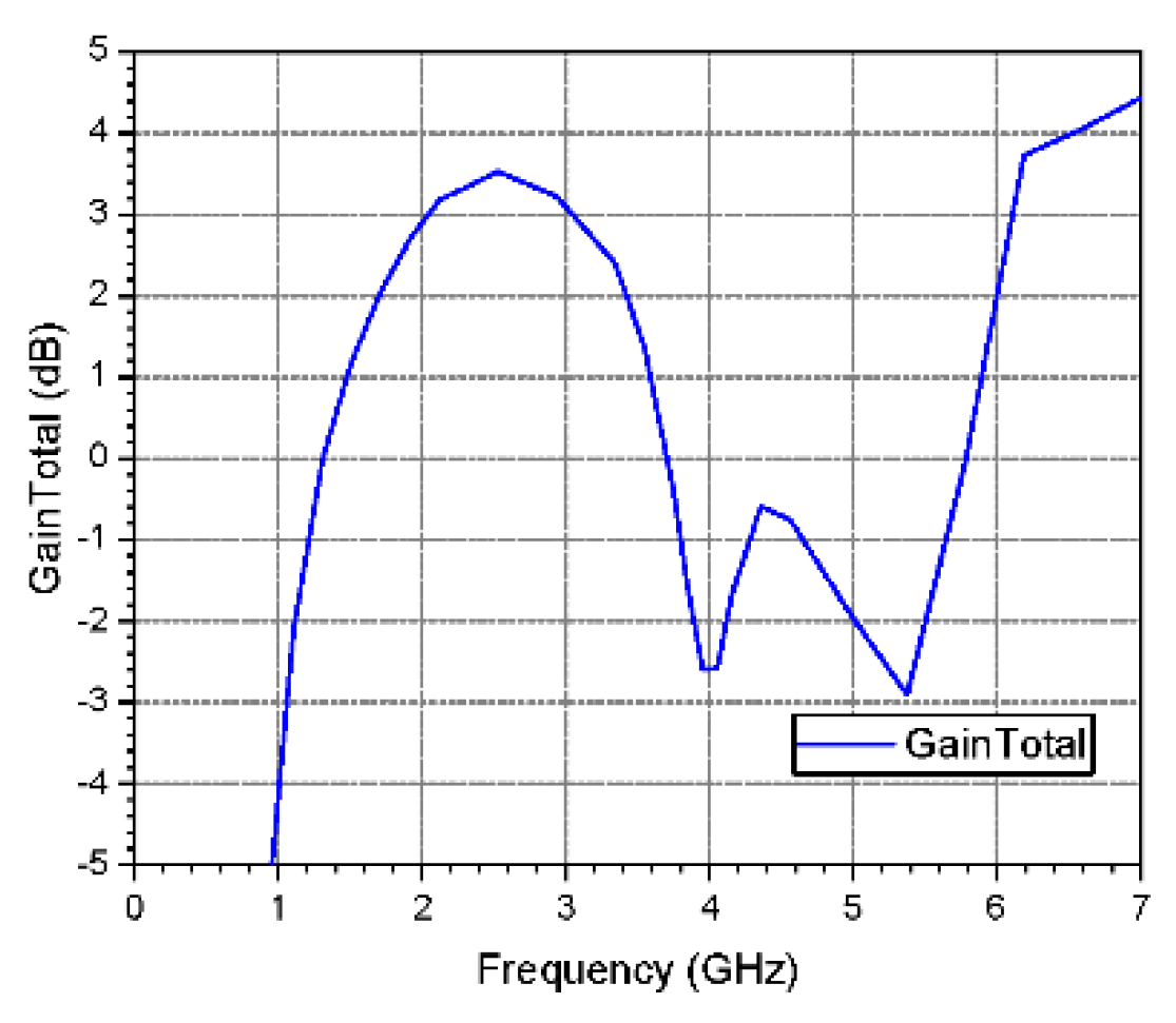
2). Gain plot: Figure 13 shows the simulated Gain results of the slot antenna with compositely-shaped patch. The simulated maximum gain is 3.5 dB, remaining above 2 dB across the antenna’s frequency range with circular polarization
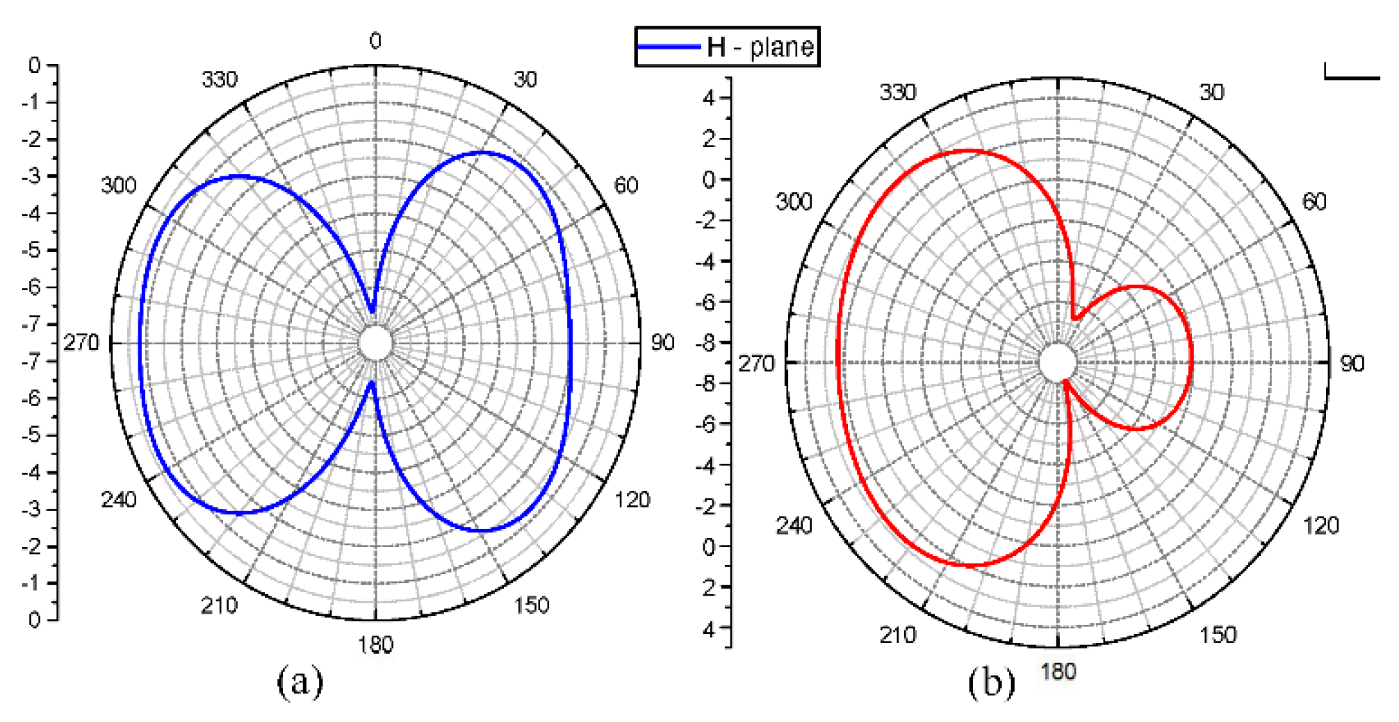
3) Radiation pattern in both the E and H planes:Figure 14 shows the simulated Radiation pattern in both E and H plan of the slot antenna with compositely-shaped patch.
5. Parametric Analysis
5.1. Parametric Analysis on Offset Feedline
1) Parametric analysis on Offset feedline using the simulated S-parameter (S11):Figure 15 shows the result of the parametric analysis on the offset feedline using the S11 plot. Offsetting the feedline improves the impedance bandwidth, and reducing the offset degrades it. An offset length of 2mm yields the optimal impedance bandwidth.
2) Parametric analysis on Offset feedline using the simulated Axial Ratio:Figure 16 shows the result of the parametric analysis on the offset feedline using the AR plot. Increasing the feedline offset improves the axial ratio bandwidth, while decreasing it degrades it.
5.2. Parametric analysis on Crescent stub
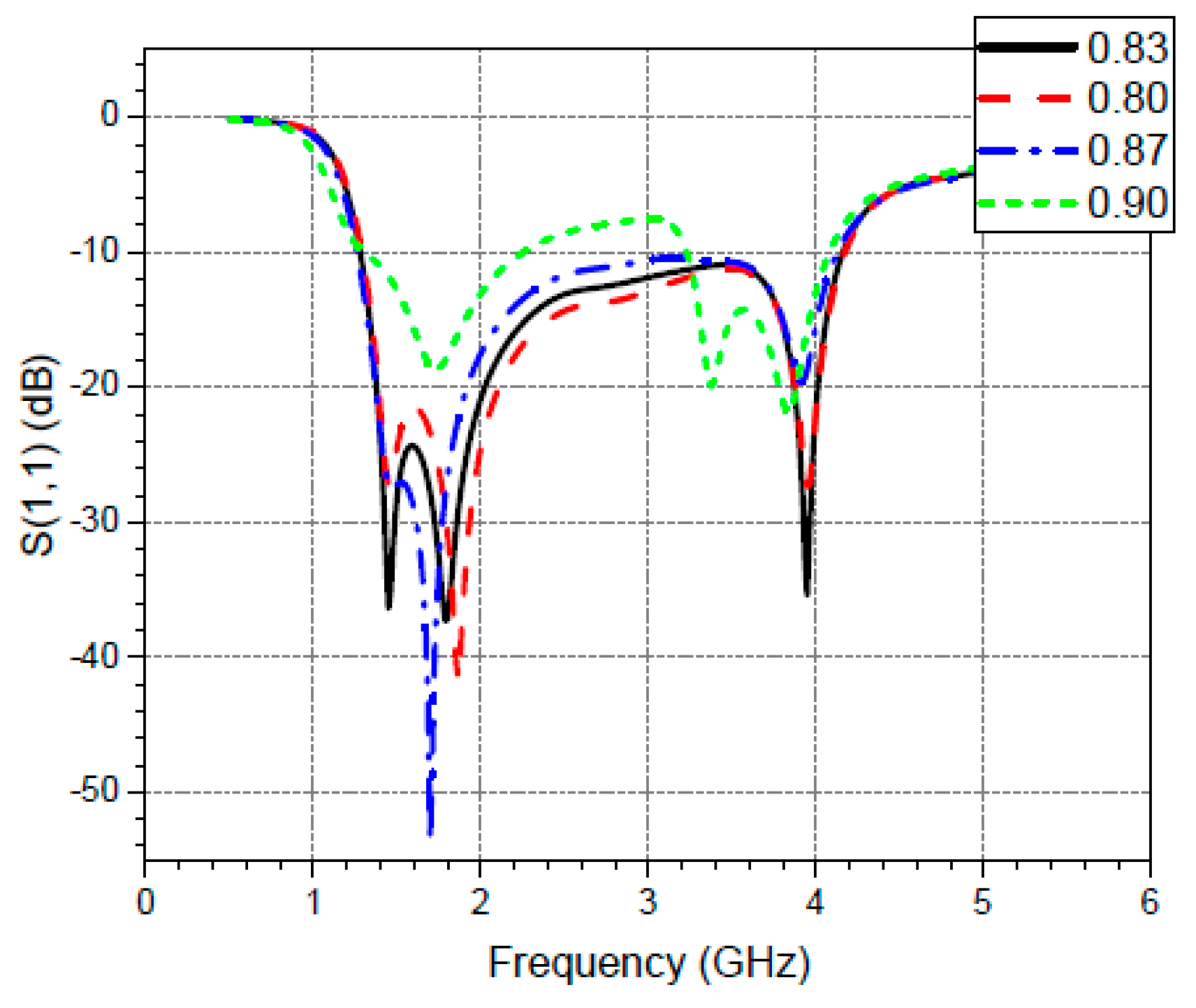
1) Parametric analysis on the Crescent stub using the simulated S-parameter (S11):Figure 17 shows the result of the parametric analysis on the Crescent stub using the S11 plot. Increasing the ratio of the ellipse forming the crescent reduces the impedance bandwidth, causing discontinuity and an increase in reflection coefficient towards the -10 dB mark.
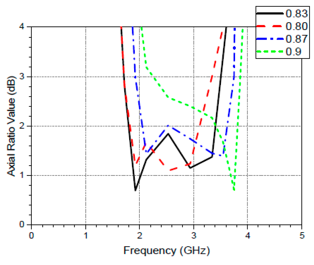
2) Parametric analysis on the Crescent stub using the simulated Axial Ratio:Figure 18 shows the result of the parametric analysis on the Crescent stub using the AR plot. Increasing the ratio of the ellipse forming the crescent significantly reduces the axial ratio bandwidth, causing it to decrease until the antenna loses circular polarization.
6. Conclusion
The antenna’s optimized operation, achieved through the addition of a crescent-shaped stub forming a compositely-shaped patch, resulted in the desired impedance and axial ratio bandwidths, as well as the resonating frequency of 1.8 GHz. The antenna has a wide return loss bandwidth and a lesser axial ratio bandwidth due to the lack of an appropriate phase difference between the excitations. Although the intended design avoids the multiple-feed technique, which can remedy this [
14] for simplicity, the axial ratio bandwidth still allows for circular polarization over a wide frequency range.
With a simulated maximum gain of 3.5 dB and gain above 2 dB across the frequency range with circular polarization, the antenna proves effective for base station applications. Its compositely-shaped patch ensures optimum performance, providing a 2.9 GHz bandwidth and a 1.8 GHz axial ratio bandwidth for circular polarization. Future plans involve fabrication, measurement, and exploring unidirectional radiation patterns using a reflector.
In conclusion, the antenna’s performance, including its gain, bandwidths, and circular polarization, makes it well-suited for base station applications.
References
- Fumiyuki Adachi, “Wireless Past and Future--Evolving Mobile Communications Systems,” IEICE Transactions on Fundamentals of Electronics, Communications and Computer Sciences Vol.E84-A No.1 pp.55-60.
- A. Giuseppe, V. Persico, A. Pescapé, “A Survey on Information and Communication Technologies for Industry 4.0: State-of-the-Art, Taxonomies, Perspectives, and Challenges,” IEEE Communications Surveys & Tutorials, 2019.
- C. Beckman, B. Lindmark, “The Evolution of Base Station Antennas for Mobile Communications,” International Conference on Electromagnetics in Advanced Applications, September 2007.
- Zhi N. Chen, K. Luk, “Antennas for Base Stations in Wireless Communications,” New York: McGraw-Hill Education, 2009.
- J. L. Volakis, “Antenna Engineering Handbook,” 4th ed. New York: McGraw-Hill Education, 2007.
- C. A. Balanis, “Antenna theory analysis and design,” John Wiley and Sons, Inc., Hoboken, New Jersey, 2005.
- Abdul Q. Khan, Muhammad Riaz, Anas Bilal, “Various Types of Antenna with Respect to their Applications: A Review,” International journal of Multidisciplinary Sciences and Engineering, vol. 7, no. 3, March 2016.
- Hanyang Wang, Dawei Zhou, Liang Xue, Steven Gao, Hang Xu, “Mode analysis and excitation of slot antennas,” Loughborough Antennas & Propagation Conference (LAPC), November 2015.
- K. H. Jingjian, Z. Xiaofa, Xie Shaoyi, Wu Weiwei, Yuan Naichang, “Suppression of Cross-Polarization of the Microstrip Integrated Balun-Fed Printed Dipole Antenna,” International Journal of Antennas and Propagation, vol. 2014. [CrossRef]
- Steven (Shichang) Gao, Qi Luo, Fuguo Zhu, “Circularly Polarized Antennas,” John Wiley & Sons Ltd., West Sussex, 2014.
- K.-W. Khoo, Y.-X. Guo, L. C. Ong, “Wideband circularly polarized dielectric resonator antenna,” IEEE Trans. Antennas Propag., vol. 55. [CrossRef]
- Y. R. C. Han, S. S. Zhong, J. Liu, “Broadband circularly polarised dielectric resonator antenna fed by wideband switched line coupler,” Electron. Lett., May 2014. [CrossRef]
- Wong, K.-L. and Chiou, T.-W. “Broad-band single-patch circularly polarized microstrip antenna with dual capacitively coupled feeds,” IEEE Trans. Antennas Propagation, 49(1), pp. 41-44(2001). [CrossRef]
- L. Sun, G. Ou, Y. Lu and S. Tan, “Axial Ratio Bandwidth of a Circularly Polarized Microstrip Antenna,” in Advancement in Microstrip Antennas with Recent Applications, London, United Kingdom: IntechOpen, 2013.
|
Disclaimer/Publisher’s Note: The statements, opinions and data contained in all publications are solely those of the individual author(s) and contributor(s) and not of MDPI and/or the editor(s). MDPI and/or the editor(s) disclaim responsibility for any injury to people or property resulting from any ideas, methods, instructions or products referred to in the content. |
© 2023 by the authors. Licensee MDPI, Basel, Switzerland. This article is an open access article distributed under the terms and conditions of the Creative Commons Attribution (CC BY) license (http://creativecommons.org/licenses/by/4.0/).
