Submitted:
06 October 2023
Posted:
10 October 2023
You are already at the latest version
Abstract
Keywords:
1. Introduction
2. Materials and Methods
2.1. Experimental
2.2. Polarization Characterization of HZO
3.1. Experimental Results
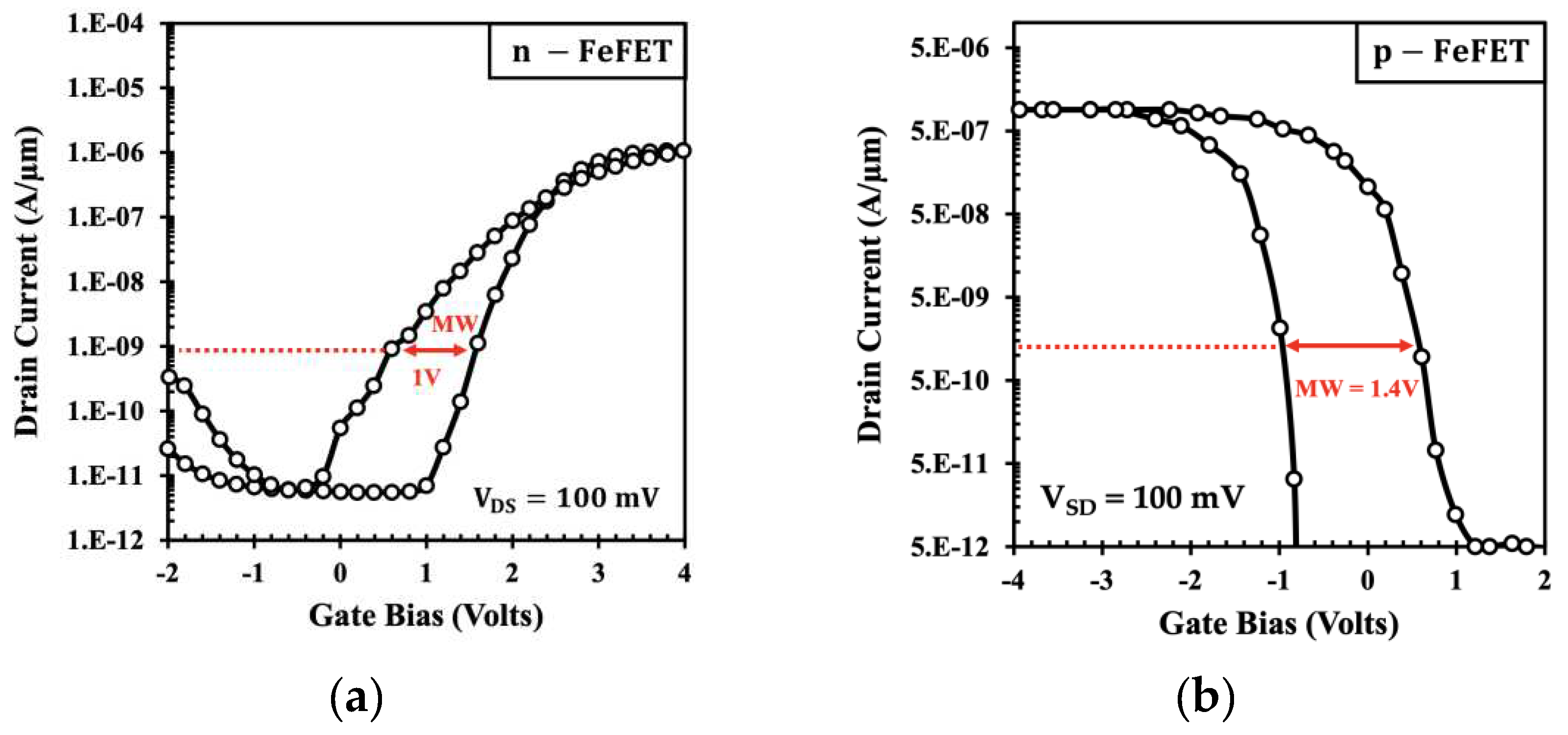
3.1.1. DC Characterization
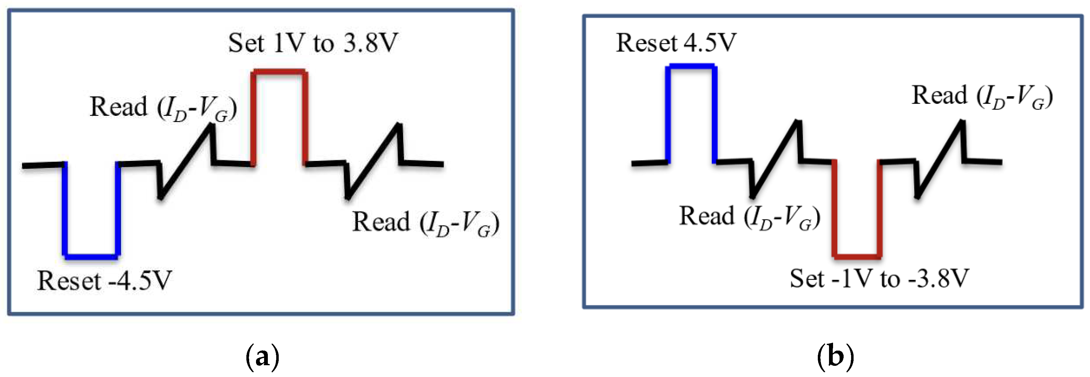
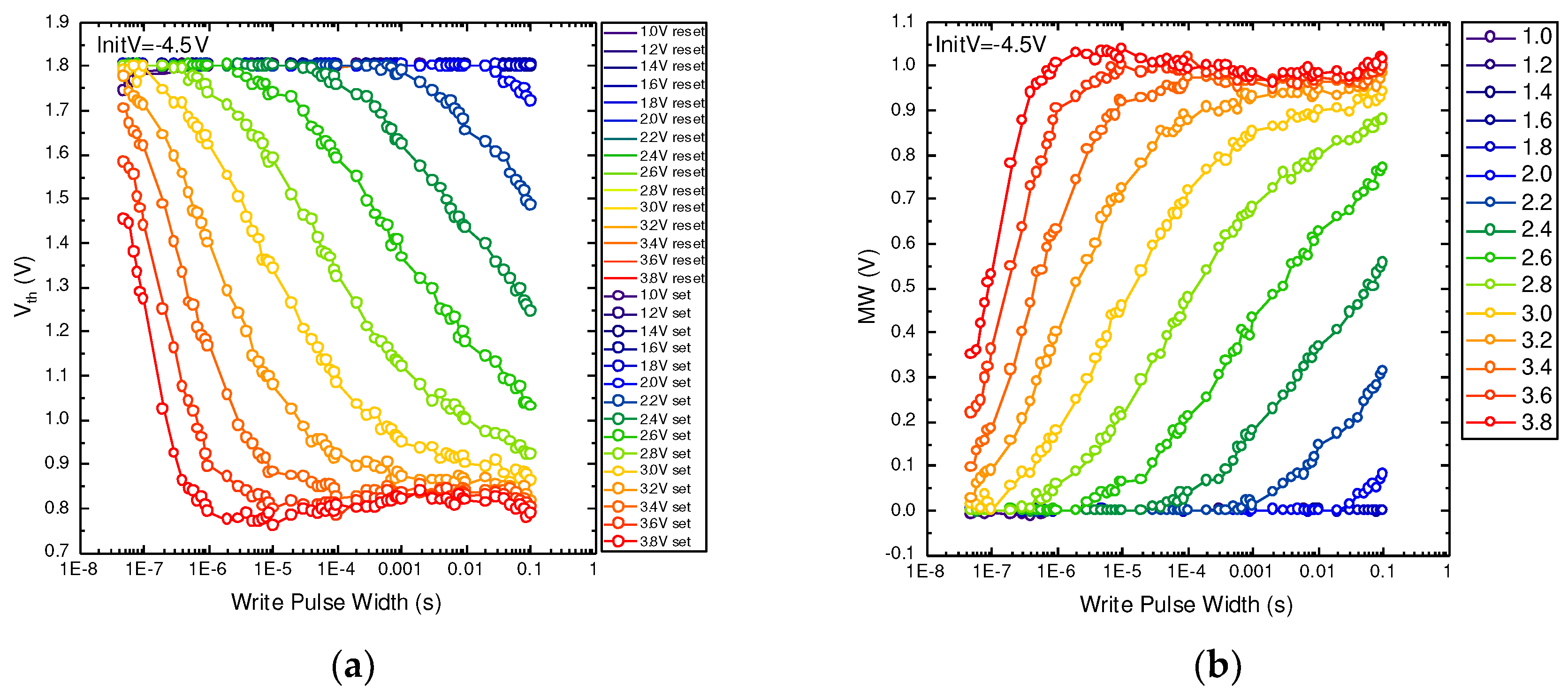
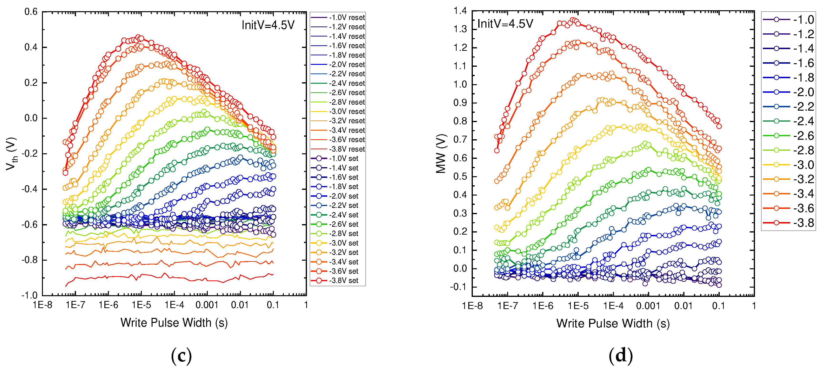
3.1.2. Pulse Characterization
3.2. Simulation Methodology
3.2.1. Calibration of the Fabricated Devices
4. Discussion
Author Contributions
Funding
Data Availability Statement
Acknowledgments
Conflicts of Interest
References
- J. Y. Kim, M. J. Y. Kim, M. -J. Choi, H. W. Jang, APL Materials, 2021, 9, 021102.
- H. Mulaosmanovic, J. H. Mulaosmanovic, J. Ocker, S. Muller, M. Noack, J. Muller, P. Polakowski, T. Mikolajick, S. Slesazeck, IEEE Symposium on VLSI Technology, 2017, T13-3, T176. [CrossRef]
- H. Mulaosmanovic, E. H. Mulaosmanovic, E. Chicca, M. Bertele, T. Mikolajick, S. Slesazeck, Nanoscale, 2018, 10, 21755.
- S. -K. Yoon, Y. -S. Youn, J. -G. Kim, S. -D. Kim, The Journal of Supercomputing, 2018, 74, 5293.
- J. C. Mogul, E. J. C. Mogul, E. Argollo, M. Shah, P. Faraboschi, Proceedings of the 12th conference on Hot topics in operating systems, 2009, 1, 14. [CrossRef]
- T. Ali, K. T. Ali, K. Mertens, K. Kühnel, M. Rudolph, S. Oehler, D. Lehninger, F. Müller, R. Revello, R. Hoffman, K. Zimmermann, T. Kämpfe, M. Czernohorsky, K. Seidel, J. van Houdt, L. M. Eng, Nanotechnology, 2021, 32, 425201.
- R. H. R. Hahnioser, R. R. H. R. Hahnioser, R. Sarpeshkar, M. A. Mahowald, R. J. Douglas, H. S. Seung, Nature, 2000, 405, 947.
- Y. Park, M.-K. Y. Park, M.-K. Kim, J.-S. Lee, Journal of Materials Chemistry C, 2020, 8, 9163.
- P. A. Merolla, J. V. P. A. Merolla, J. V. Arthur, R. Alvarez-icaza, A. S. Cassidy, J. Sawada, F. Akopyan, B. L. Jackson, N. Imam, C. Guo, Y. Nakamura, B. Brezzo, I. Vo, S. K. Esser, R. Appuswamy, B. Taba, A. Amir, M. D. Flickner, W. P. Risk, R. Manohar, D. S. Modha, Science, 2014, 345, 668.
- V. A. Isupov, Ferroelectrics, 2002, 266, 91.
- C. -C. Chung, Ph.D. Thesis, University of Connecticut, 2014, 293. Available at: https://opencommons.uconn.edu/dissertations/293/.
- S. Bhalla, R. S. Bhalla, R. Guo, and E. F. Alberta, Materials Letters, 2002, 54, 264.
- H. Zhu, S. H. Zhu, S. Yamamoto, J. Matsui, T. Miyashita, M. Mitsuishi, RSC Advances, 2018, 8, 7963.
- T. Furukawa, Phase Transitions, 1989, 18(3-4), 143.
- J. Wang, H. J. Wang, H. Li, J. Liu, Y. Duan, S. Jiang, S. Yan, Journal of the American Chemical Society, 2003, 125, 1496.
- J. Lovinger, Macromolecules, 1981, 14, 322.
- S. J. Kim, J. S. J. Kim, J. Mohan, J. Lee, J. S. Lee, A. T. Lucero, C. D. Young, L. Colombo, S. R. Summerfelt, T. San, J. Kim, Applied Physisc Letters, 2018, 112, 172902.
- T. S. Böscke, J. T. S. Böscke, J. Müller, D. Bräuhaus, U. Schröder, U. Böttger, Applied Physics Letters, 2011, 99, 102903.
- S. J. Kim, J. S. J. Kim, J. Mohan, S. R. Summerfelt, J. Kim, The Journal of The Minerals, Metals & Materials Society, 2019, 71, 246.
- K. Ni, P. K. Ni, P. Sharma, J. Zhang, M. Jerry, J. A. Smith, K. Tapily, R. Clark, S. Mahapatra, S. Dutta, IEEE Transactions on Electron Devices, 2018, 65, 2461.
- M. H. Park, Y. H. M. H. Park, Y. H. Lee, H. J. Kim, Y. J. Kim, T. Moon, K. D. Kim, J. Müller, A. Kersch, U. Schroeder, T. Mikolajick, C. S. Hwang, Advanced Materials, 2015, 27, 1811.
- P. Sharma, K. P. Sharma, K. Tapily, A. K. Saha, J. Zhang, A. Shaughnessy, A. Aziz, G. L. Snider, S. Gupta, R. D. Clark, S. Datta, IEEE Symposium on VLSI Technology, 2017, T12-2, T154. [CrossRef]
- P. D. Lomenzo, S. P. D. Lomenzo, S. Jachalke, H. Stoecker, E. Mehner, C. Richter, T. Mikolajick, U. Schroeder, Nano Energy, 2020, 74, 104733.
- J. D. Anderson, J. J. D. Anderson, J. Merkel, D. Macmahon, & S. Kurinec, "Evaluation of Si:HfO2 Ferroelectric Properties in MFM and MFIS Structures," IEEE Journal of the Electron Devices Society, vol. 6, pp. 525-534, 2018.
- S. Deng, Z. S. Deng, Z. Jiang, S. Dutta, H. Ye, W. Chakraborty, S. Kurinec, & K. Ni, "Examination of the interplay between polarization switching and charge trapping in ferroelectric FET," in IEEE International Electron Devices Meeting (IEDM), 2020. [CrossRef]
- E. Yurchuk, J. E. Yurchuk, J. Müller, S. Müller, J. Paul, M. Pešić, R. van Bentum, U. Schroeder, T. Mikolajick, IEEE Transactions on Electron Devices, 2016, 63, 3501.
- H. -T. Lue, C. H. -T. Lue, C. -J. Wu, T. -Y. Tesng, IEEE Transactions on Electron Devices, 2002, 49, 1790.
- RIT Semiconductor & Microsystems Fabrication Laboratory. Available online: http://www.smfl.rit.edu (accessed on September 29th, 2023).
- VICTORY Device User’s Manual, Silvaco Inc., Santa Clara, CA, USA, 2015.
- H. Bae, S. G. H. Bae, S. G. Nam, T. Moon, Y. Lee, S. Jo, D. - H. Choe, S. Kim, K. -H. Lee, J. Heo, IEEE International Electron Devices Meeting (IEDM), 2020, 31.3.1. [CrossRef]
- D. Kuzum, J. D. Kuzum, J. -H. Park, T. Krishnamohan, H. -S. P. Wong, K. C. Saraswat, IEEE Transactions on Electron Devices, 2011, 58, 1015.
- Lombardi, C.; Manzini, S.; Saporito, A.; Vanzi, M. A physically based mobility model for numerical simulation of nonplanar devices. IEEE Trans. Comput. Des. Integr. Circuits Syst. 1988, 7, 1164–1171. [Google Scholar] [CrossRef]
- I. Khan, A. I. Khan, A. Keshavarzi, S. Datta, Nature Electronics, 2020, 3, 588.
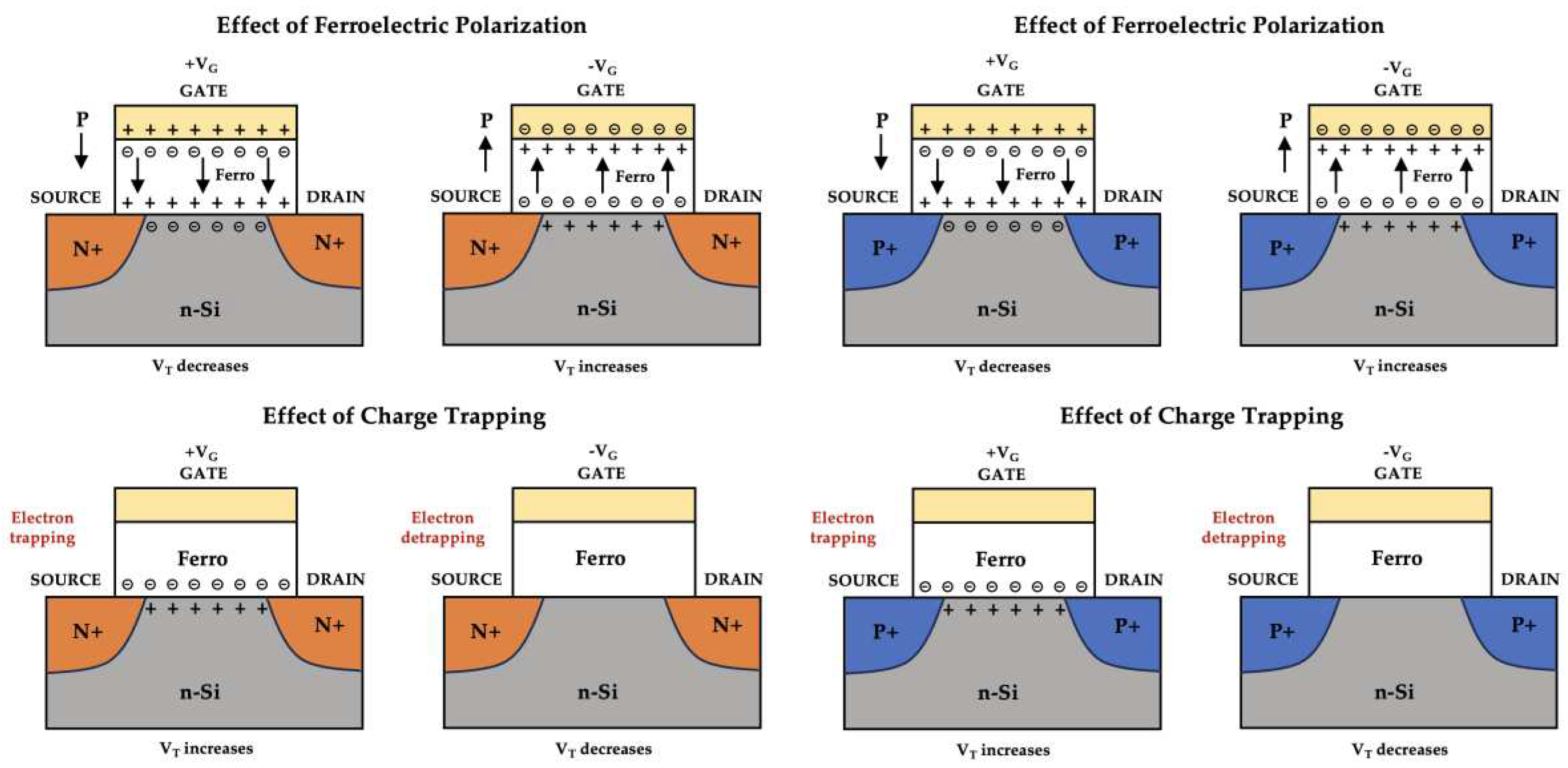
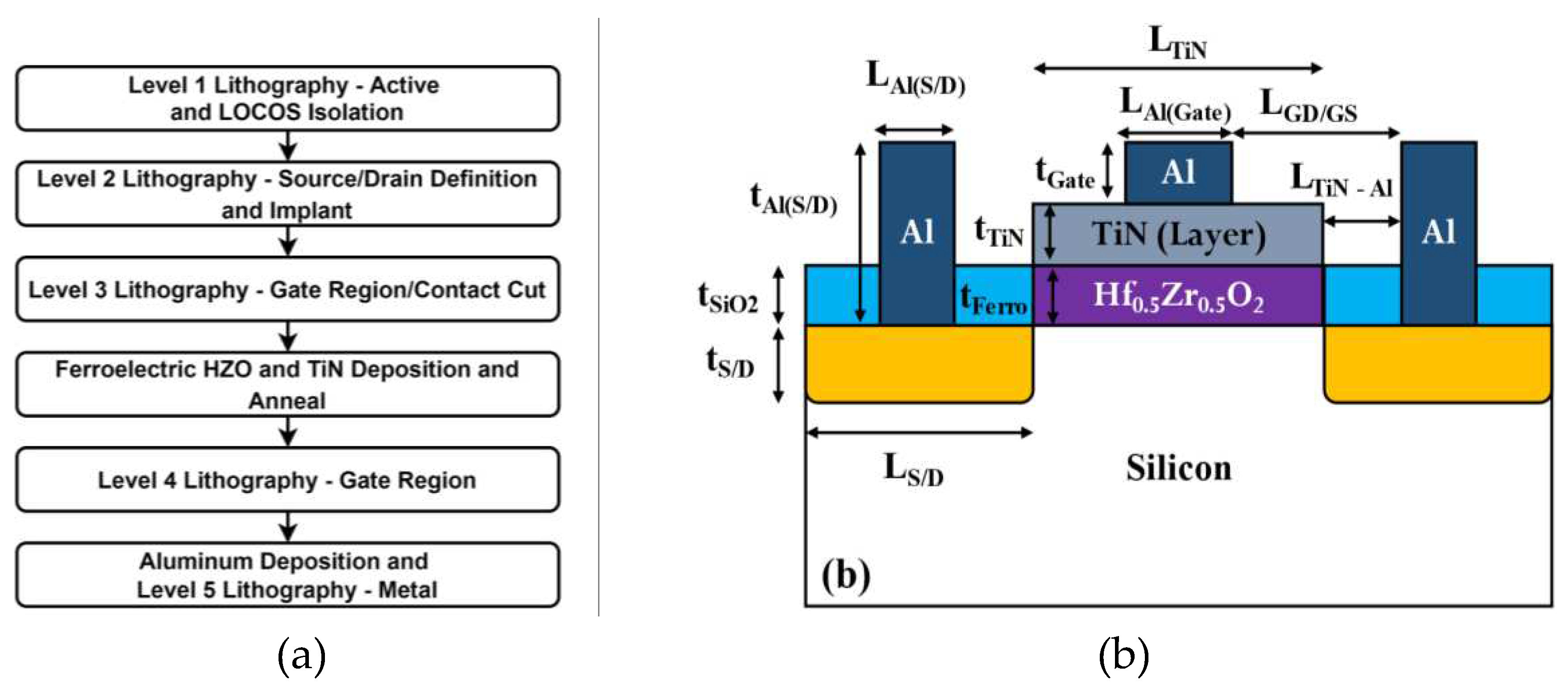
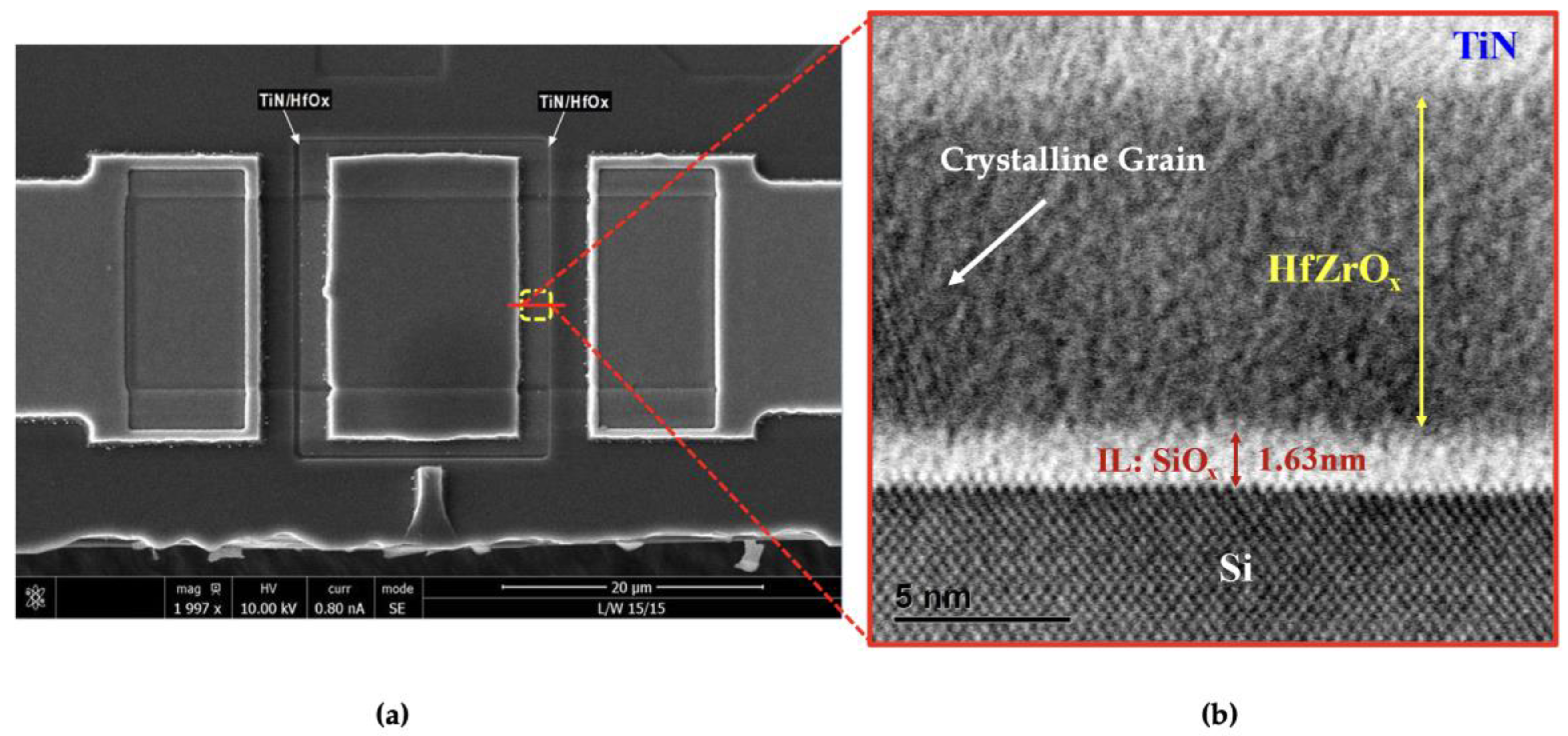
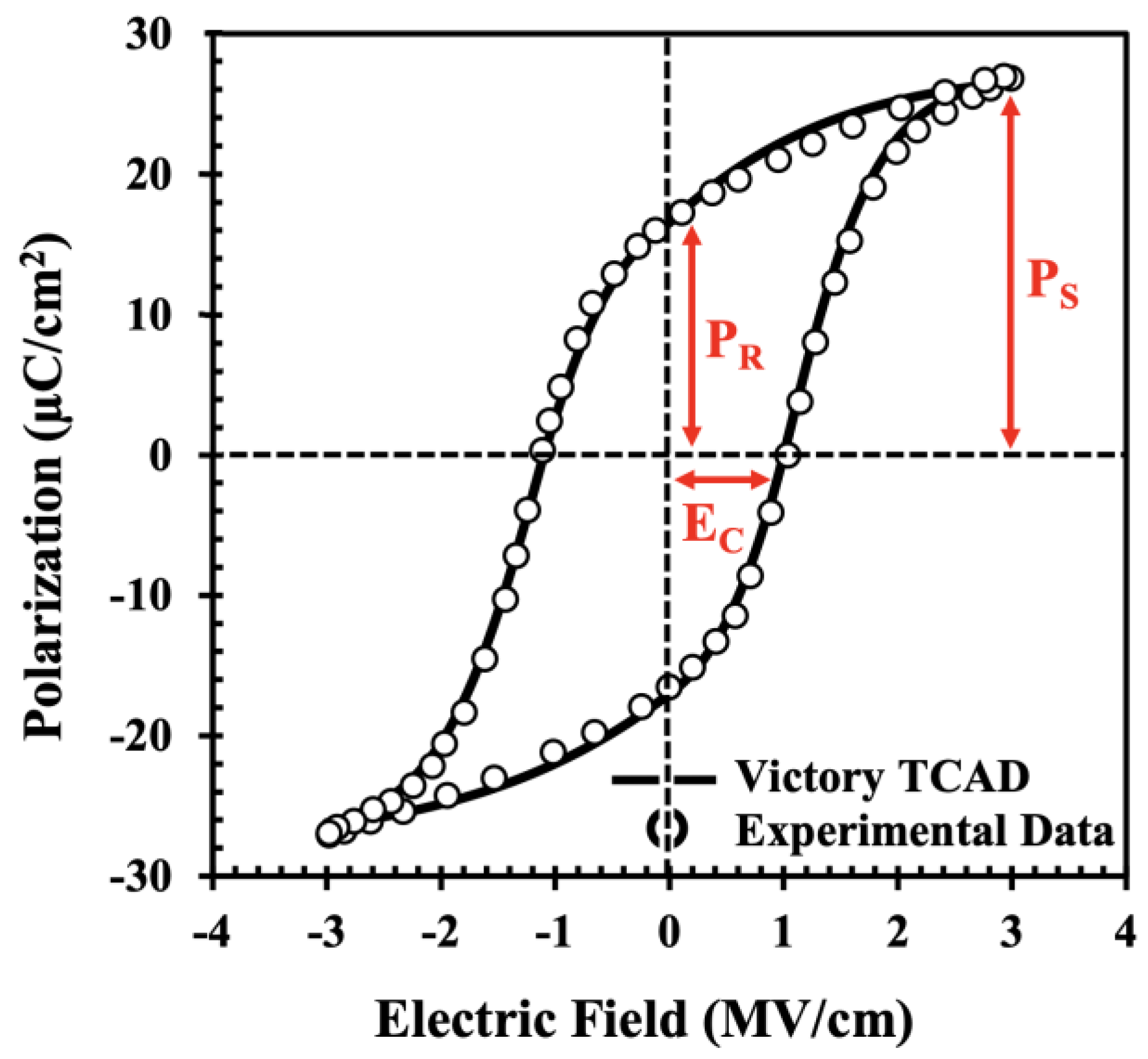
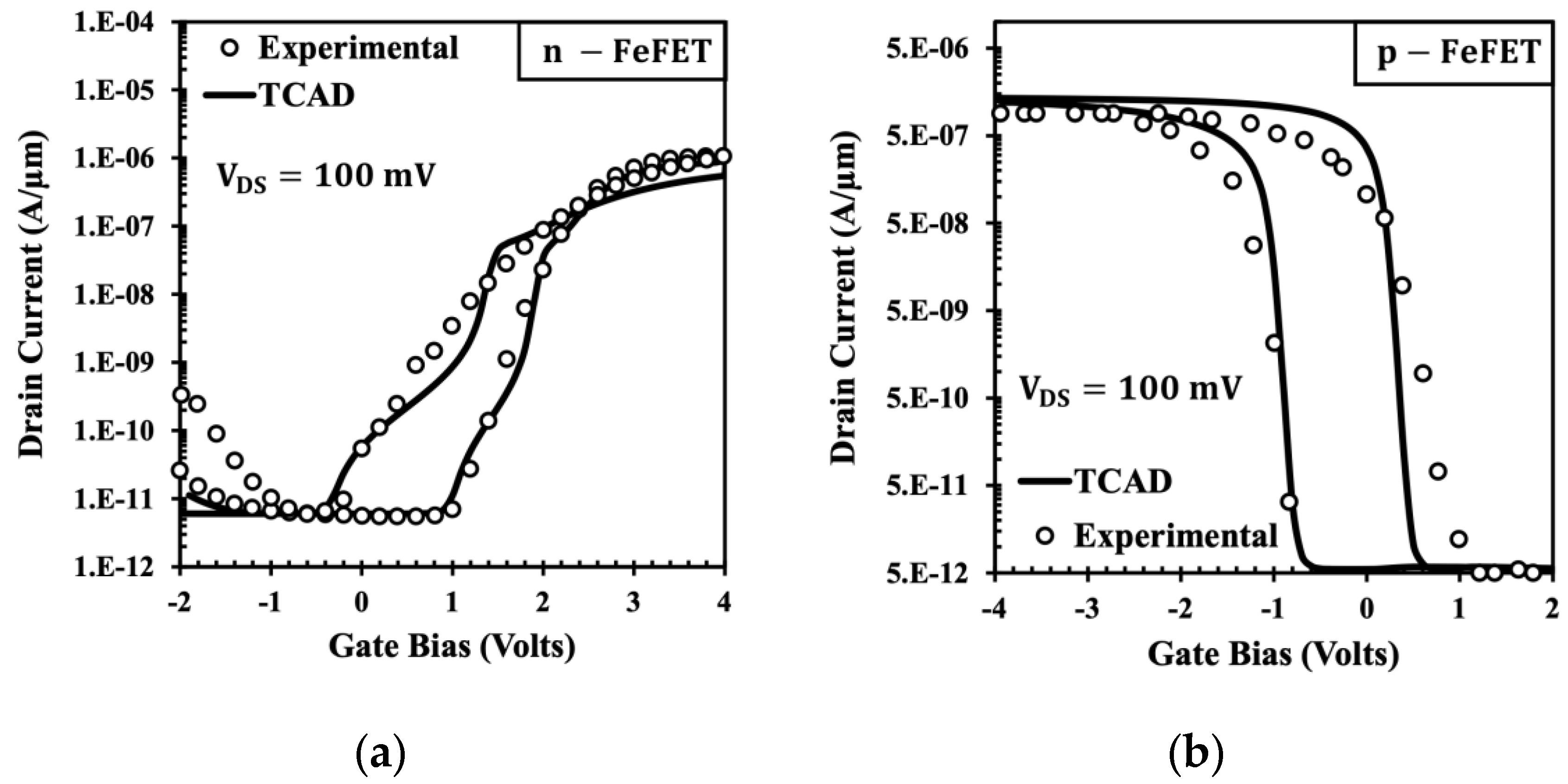
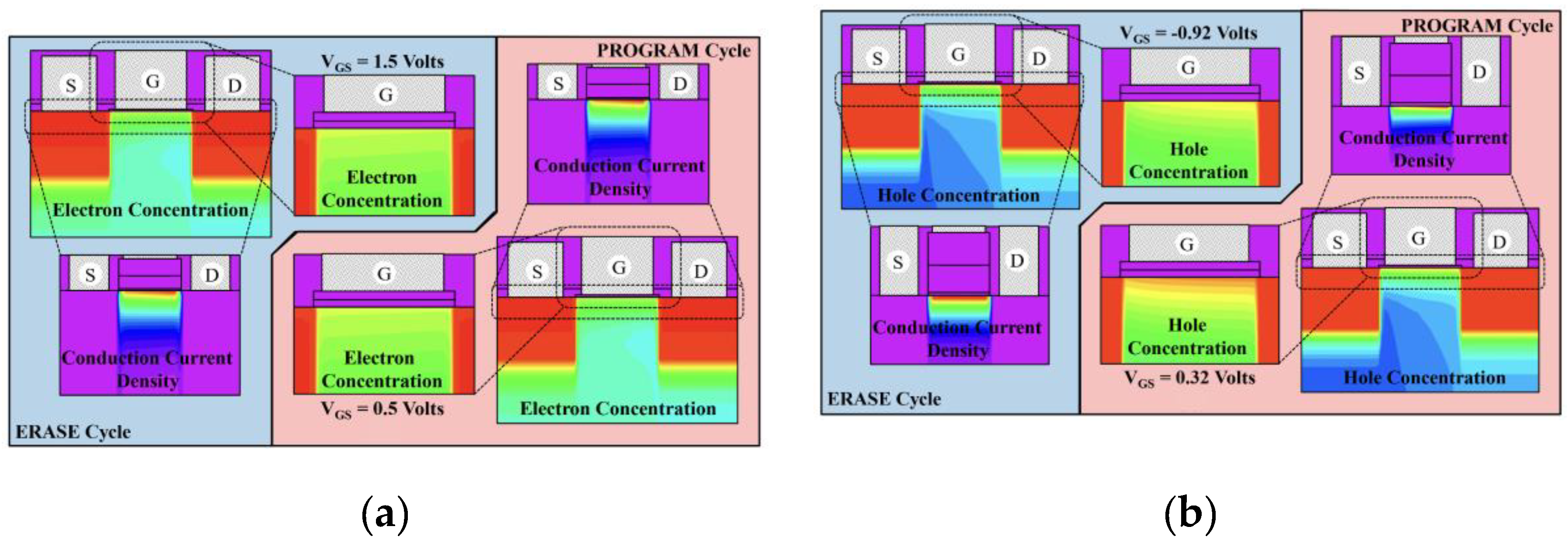
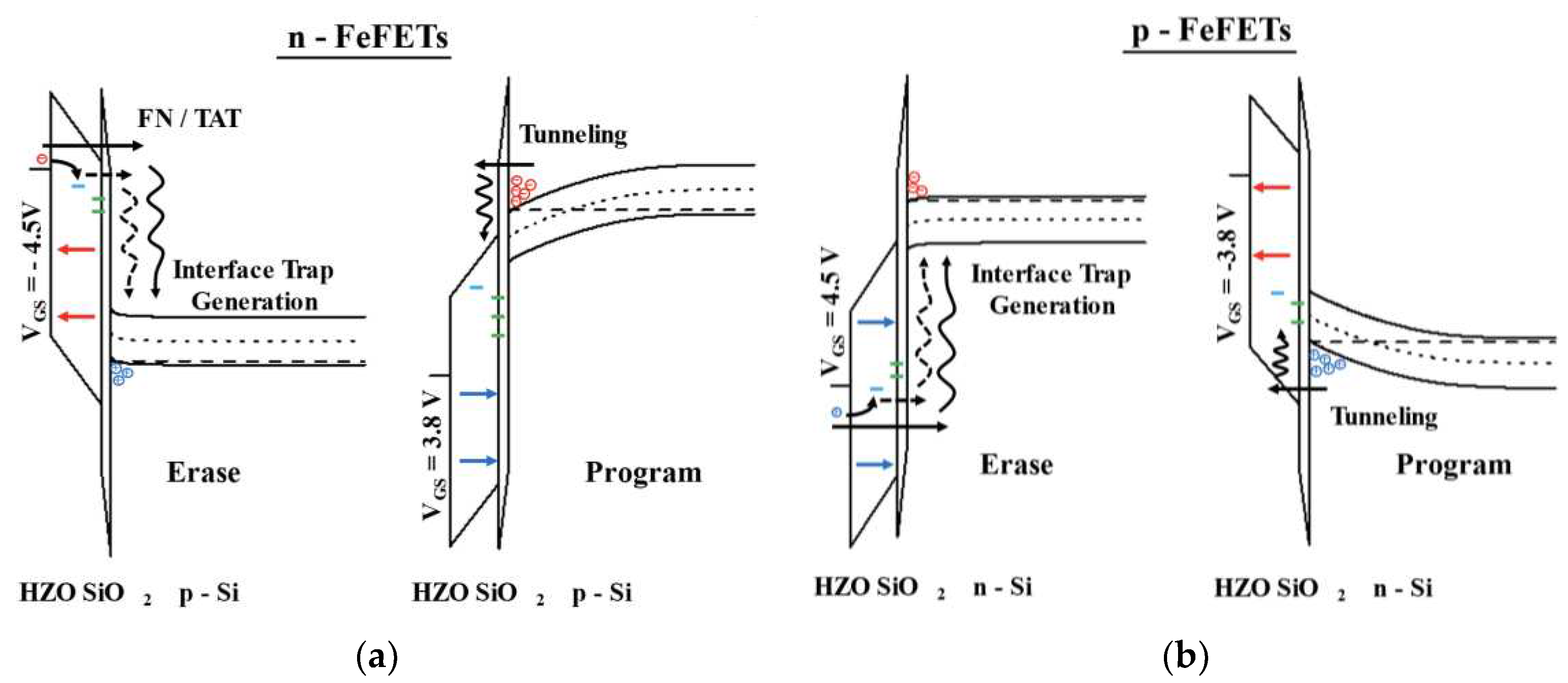
| Symbols | Description | Value |
|---|---|---|
| ND/S | Source/Drain Doping | 2 x 1019 cm-3 |
| NSubs | Substrate Doping | 2 x 1015 cm-3 |
| tS/D | Junction depth of Source/Drain | 0.8 µm |
| LS/D | Lateral Extensions of Source/Drain | 13 µm |
| tSiO2 | Thickness of Silicon Dioxide | 100 nm |
| tFerro | Thickness of Ferro Layer | 10 nm |
| tTiN | Thickness of TiN Layer | 12 nm |
| tGate | Thickness of Al Gate Contact | 750 nm |
| tAl(S/D) | Thickness of Al Source/Drain Contact | 750 nm |
| LAl(S/D) | Length of Al Source/Drain Contact | 9 µm |
Disclaimer/Publisher’s Note: The statements, opinions and data contained in all publications are solely those of the individual author(s) and contributor(s) and not of MDPI and/or the editor(s). MDPI and/or the editor(s) disclaim responsibility for any injury to people or property resulting from any ideas, methods, instructions or products referred to in the content. |
© 2023 by the authors. Licensee MDPI, Basel, Switzerland. This article is an open access article distributed under the terms and conditions of the Creative Commons Attribution (CC BY) license (https://creativecommons.org/licenses/by/4.0/).


