1. Introduction
LiFi (Light Fidelity) [
1,
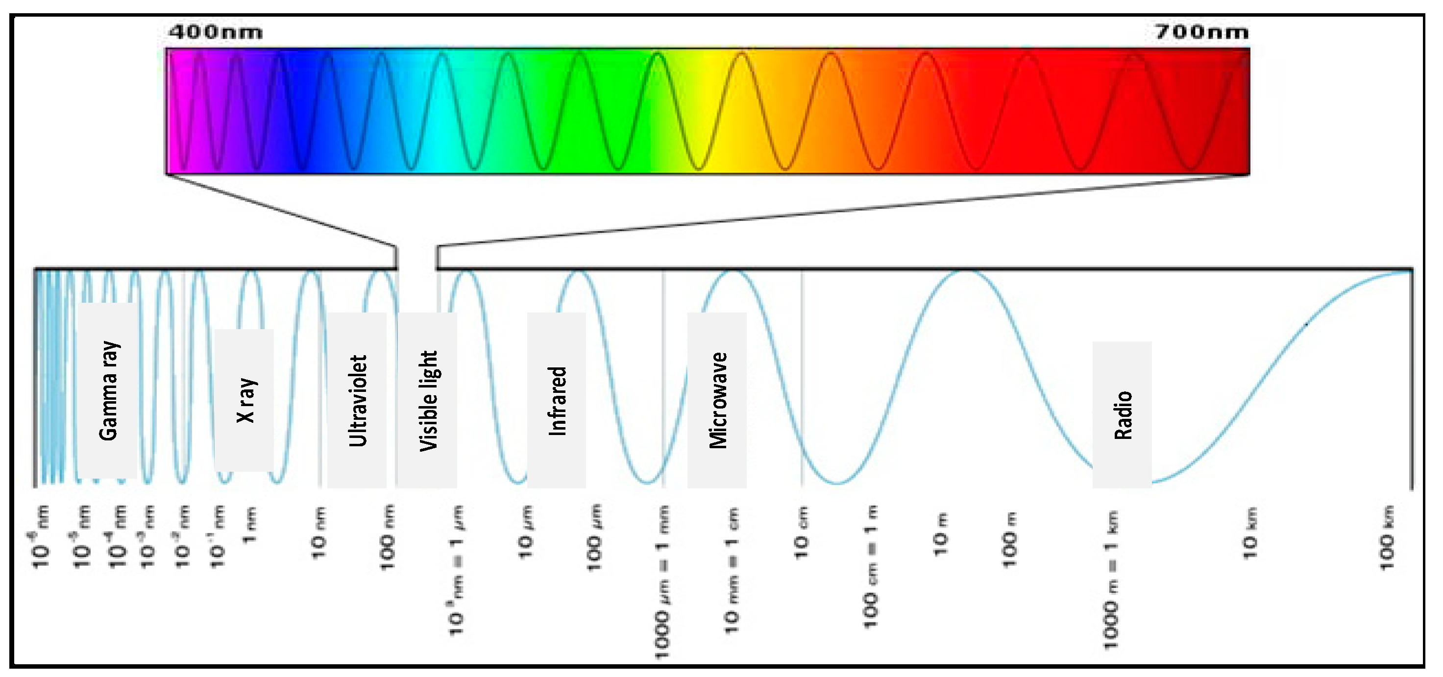
2] is a wireless communication technology based on the use of visible light between 480 nm (670 THz) and 650 nm (460 THz), unlike WiFi which uses the radio part of the electromagnetic spectrum. See
Figure 1. By turning an LED (Light Emitting Diode) on and off several thousand or even millions of times per second, it is possible to transmit sound, video, or even the Internet with speeds that can range from order of 10 Gb/s in theory.
LiFi is used to describe VLC (Visible Light Communication) [
3] which is a high-speed wireless communication technology. It acquired this name due to the similarity with WiFi (Wireless Fidelity), using only light instead of radio waves. LiFi is mainly based on VLC governed by seven working groups of IEEE 802.15 standard, (IEEE 802, part 15, 2011) [
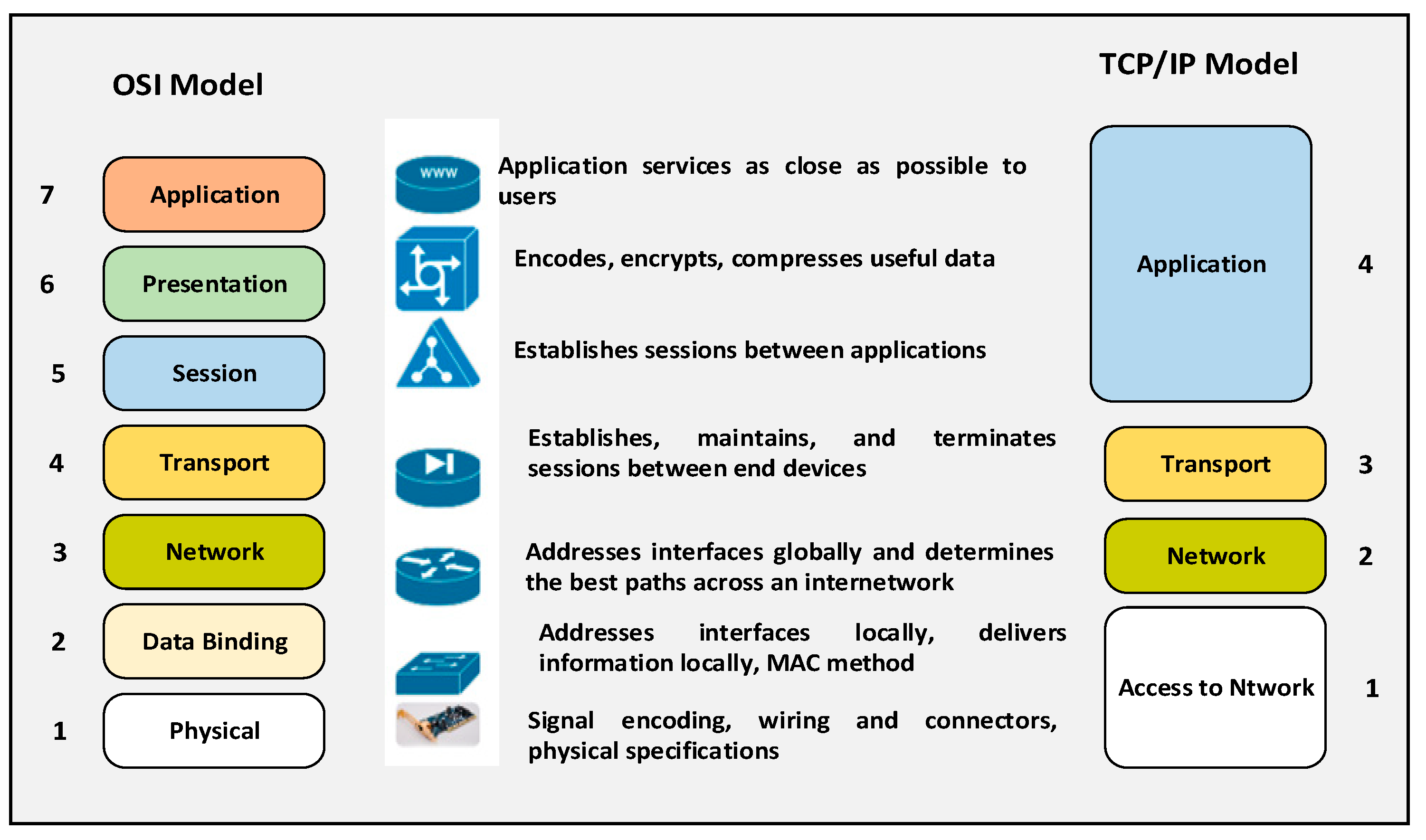
4] standardizing all wireless communications using visible light (450 nm to 760 nm). This standard defines the PHY (physical) and the MAC (Media Access Control) layers. The standard imposes the delivery of sufficient bit rates to transmit audio, video, and multimedia services. It also considers the mobility of optical transmission, its compatibility with artificial lighting present in the infrastructure, and the deficiencies that may result from the interference generated by the ambient lighting. The MAC layer makes it possible to establish the link with the upper layers of other protocols such as TCP/IP (Transmission Control Protocol/Internet Protocol). Finally, the standard complies with current regulations on user eye safety [
5]. See
Figure 2.
The IEEE 802.15.7 [
6] standard, however, still fails to consider the latest technological developments in the field of wireless optical communications, in particular the introduction of O-OFDM (Optical Orthogonal Frequency Division Multiplexing) [
7] which is a technical modulation and optimization of data rate, multiple access, energy efficiency.
The standard [
8] defines three PHY layers according to the speeds considered:
PHY I: Outdoor applications, data rate from 11.67 kb/s to 266.6 kb/s.
PHY II: Indoor applications, throughput from 1.25 Mb/s to 96 Mb/s.
PHY III: multiple transmitting sources, CSK (Color-Shift Keying) modulation, data rate from 12 Mb/s to 96 Mb/s.
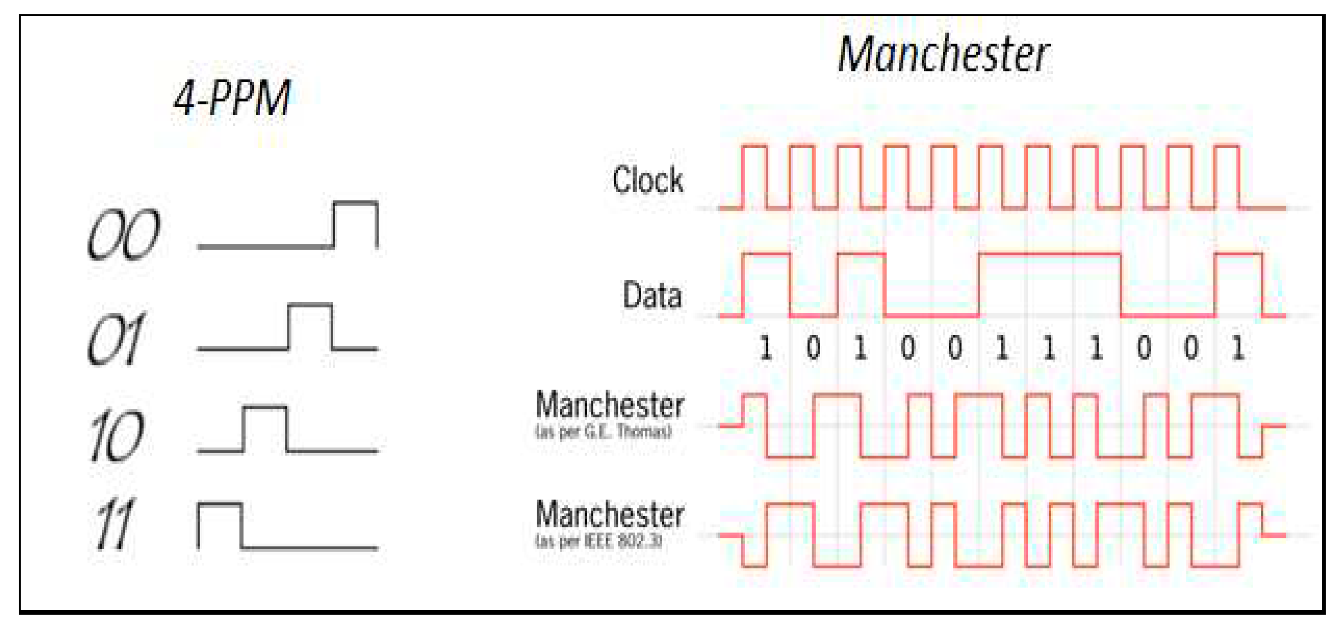
The recommended modulation formats for PHY I and PHY II are OOK (on-off keying) and VPPM (Variable Pulse-Position Modulation) coding [
9]. Manchester coding [
10] used for the PHY I and PHY II layers embeds the clock in the transmitted data by representing a logical 0 by an OOK symbol of “01” and a logical 1 by an OOK symbol of “10” with a DC component. This point is important because the DC component makes it possible to avoid the extinction of the light during a prolonged series of logical 0s.
Based on the visible spectrum (from 400 nm to 750 nm) (see
Figure 1) to transmit and receive information, LiFi operates on an unlimited band and does not require a license to transmit, therefore free band at the current time.
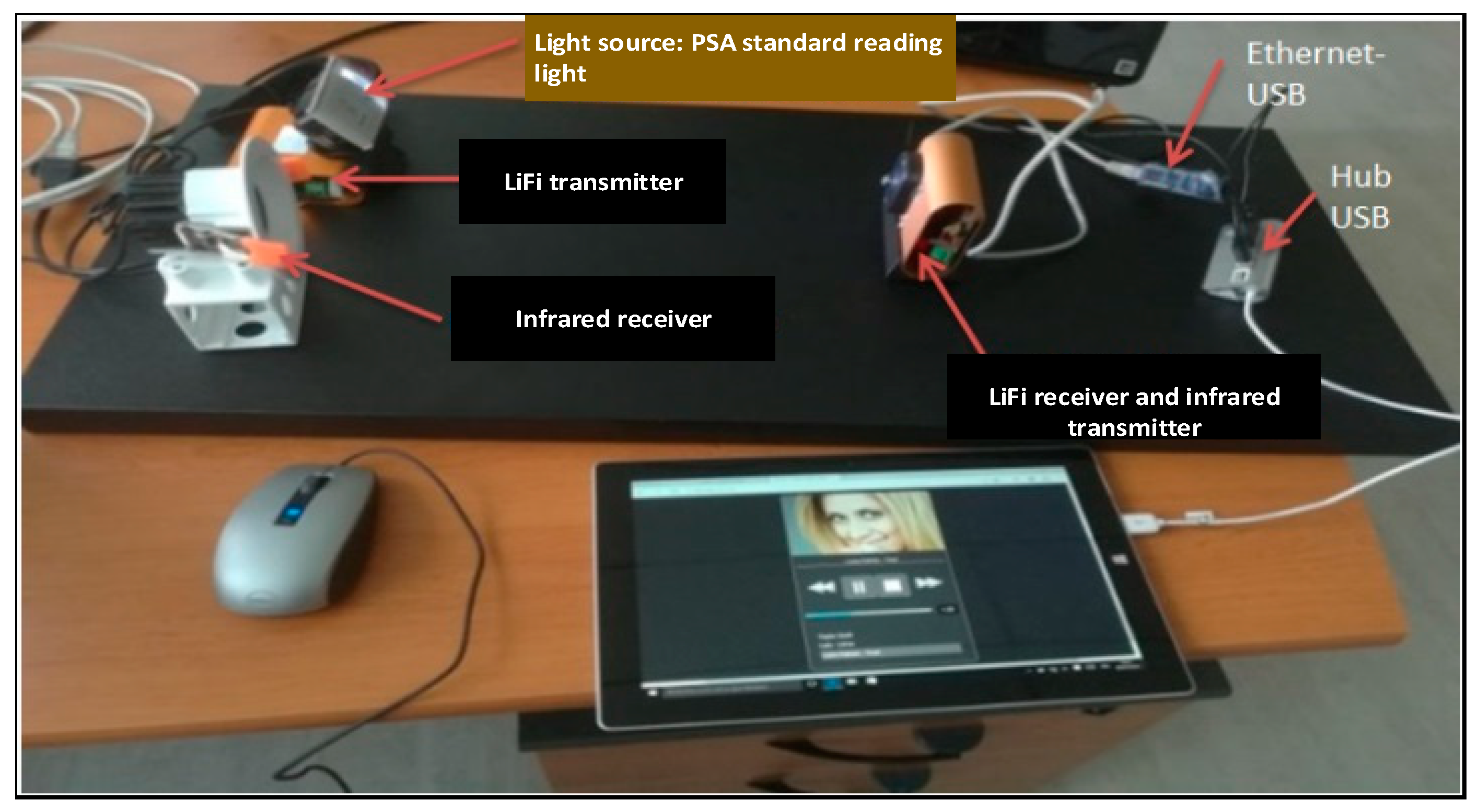
2. Context and Objectives
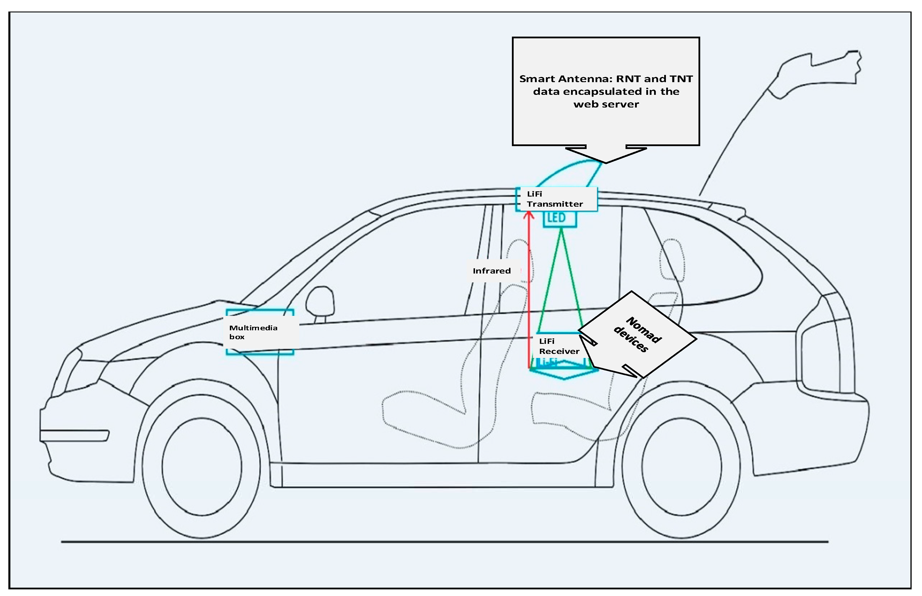
The goal of this research project is within a vehicle, to broadcast data from an antenna to mobile devices such as tablets or smartphones via LiFi for rear passengers via a web application. See
Figure 4.
This project aims to create a functional demonstrator of a two-way LiFi communication between the reading light of a vehicle and a portable device such as a tablet or smartphone. This nomadic device must display, via a dedicated interface, data in real time. The data is RNT (Digital Terrestrial Radio) and TNT (Digital Terrestrial Television) provided by an antenna developed in-house which we will call Smart Antenna. This “information” is encapsulated in web pages hosted in the antenna.
The uplink, which is done in infrared, is used to call these web pages. Note that free internet surfing is also possible (listening to web radio, watching YouTube, etc.). Initially, the study mainly targets a single user. Sometime in the future, a multi-user prototype is to be considered, if the performances of the first one are validated.
As part of this study, the objective of the project is to obtain a functional demonstrator of two-way LiFi communication for the passenger compartment of a vehicle. The purpose of this study is to decide on the feasibility of this type of communication in an automotive context, to characterize its performances (throughput, error rate, influence of environmental conditions, etc.) and to see the complementarity in relation to other types of communication (such as Wi-Fi or Bluetooth, for example). Depending on the results, the demonstrator will be integrated into a PSA Peugeot-Citroen[1] vehicle, which happens to be an integral partner in this research undertaking.
The context in which the study takes place is as follows: this study is carried out as part of a collaboration with the LISV laboratory of the University of Versailles – Paris-Saclay[2]. Thus, the work focuses on the integration of a LiFi module provided by LISV (and developed by the start-up company OLEDCOMM[3]) for intra-vehicle communication, and the characterization of the performance of the prototype. It is carried out mainly on the premises of LISV.
3. Related Works
Various works related to LiFi are available in the literature. For example, the subject of visible light communication to which LiFi was extensively discussed in [
3,
11,
12,
13,
14]. LiFi’s features including capacity, efficiency, safety, deployment, and other issues are discussed in [
15,
16]. Various works discussed the comparison of LiFi against WiFi [
12,
13,
17,
18] as well as the strengths, weaknesses, and application of LiFi in a different environment. Leba et al. [
19] discuss the challenges in the communication and modulation in LiFi. Likewise, [
20] discussed the challenges in various LiFi applications. The LiFi-based IoT architecture was presented in [
21]. In [
22], the authors introduces different LiFi applications for various places (rooms, homes, and supermarkets). Another paper presents LiFi’s application in constructions [
23]. And yet another one discusses the suitability of LiFi in monitoring and billing application [
24]. Another interesting LiFi application in the field of mobility is [
25], which supports blind people by sending them audio feedback. The role of LiFi in safe communication in an intelligent transportation system [
3,
26,
27] is discussed briefly in [
28] and [
29]. A vehicle-vehicle communication using LiFi is discussed in [
30]. The treatment, however, of those papers in intelligent transportation system is, to us, shallow. In this paper, we are offering a profound work on LiFi for intelligent transportation system, in particular for intra-vehicular data transmission application. In particular, we wish to contribute to the domain of exploring the role of LiFi in enhancing autonomous vehicles and intelligent transportation systems.
We believe that LiFi is going to be a game-changer in the realm of autonomous vehicles and intelligent transportation systems, where reliable, high-speed communication is crucial.
In intelligent transportation systems, LiFi will play an important role in vehicle-to-vehicle (V2V) and vehicle-to-infrastructure (V2I) communications. For instance, traffic lights equipped with LiFi technology can transmit data to approaching vehicles, informing them about the status of the light or any upcoming traffic congestion. Similarly, vehicles can communicate their location, speed, and direction to nearby vehicles, preventing collisions and improving road safety.
This paper is a continuation of our previous paper [
31] related to ADAS (advanced driving system) [
32] where we presented a bird’s eye view of LiFi in intra-vehicular data transmission system. Here in this paper, we demonstrate the full details of our work. In concept, this work is functional. It must be noted however that there are still several points for improvement for this research project.
4. Principle of Operation of LiFi
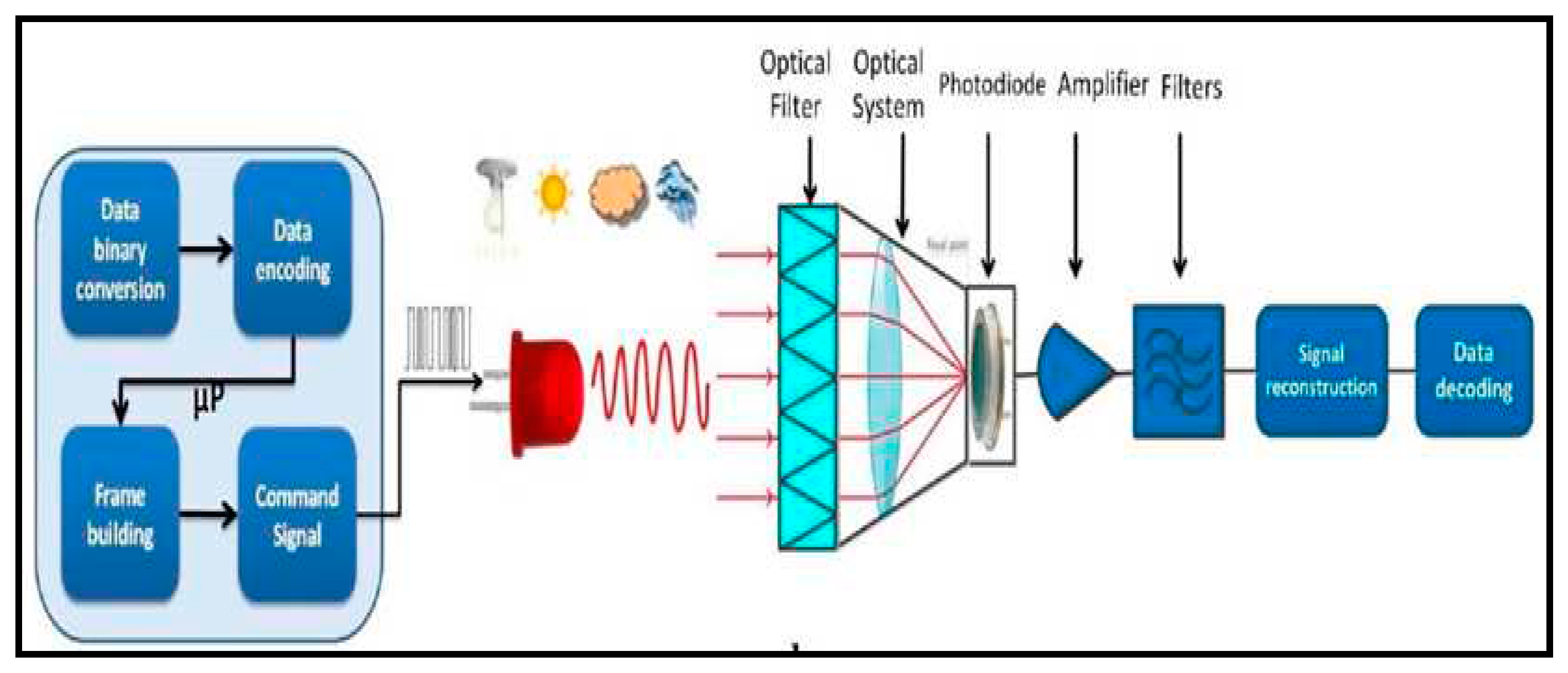
LiFi is a technology that transforms a light source into a broadcaster of digital content. By turning LED on and off several thousand or even millions of times per second, we can be able to transmit sound, video, or even the Internet with speed that can range in the order of 10 Gb/s, in theory. The architecture of a LiFi system includes a transmitter, an LED, and a receiver. See
Figure 5. The transmitter does modulate the data to be sent using a selected coding and then control the LED source. Data is thus transmitted by switching on and off a high-frequency LED. A photodiode encapsulated in the receiver captures the light from the LED and transforms it into an electrical signal [
33]. An optical filter system may be integrated in the photodiode in order to eliminate ambient lights. The electrical signal is then processed by an amplifier and filters it in order to reconstruct the useful signal. And finally, the demodulation of the signal is done to retrieve the sent signal [
34].
It should be noted that a data frame comprising the message information, such as the start bit and the stop bit, as well as the length of the message, is essential for transmission.
4.1. LiFi vs. WiFi
LiFi has many advantages that come from the use of visible light on the one hand, and the use of LEDs on the other. They are given below:
LEDs can be easily modulated at very high speed, which makes it possible to achieve high data rates without using complex techniques.
Visible light, unlike radio waves, cannot pass through walls which ensures the partitioning of data but limits its indoors range.
LEDs consume little energy and have a fairly long lifespan. The interior and exterior lighting of buildings, road infrastructures and automobiles can directly provide a pre-existing mesh for the deployment of LiFi.
Unlike the radio wave that WiFi uses, LiFi’s visible light has no influence on health.
The light spectrum covers a frequency band of about 300 THz. The use of this band is also unregulated and is therefore free. LiFi and its 300 THz spectral band could therefore be used to relieve the radio band.
It should be noted that the noise coming from many sources of ambient light, including the sun and artificial light, is a major drawback of LiFi. It can influence data transmission, even saturate the receiver, and thus block communication. On the other hand, LiFi is originally unidirectional. It must therefore be coupled with another technology (WiFi) or be used in special cases (need only downlink speed). Indeed, we cannot have two light beams that intersect while simultaneously collecting data coming from two beams. Often, the uplink is via infrared. The
Table 1 below clearly illustrates the pros and cons of LiFi over WiFi:
4.2. Applications of LiFi in Various Domains
LiFi has many advantages that come from the use of visible light on the one hand, and the use of LEDs on the other. Having taken note of the advantages of LiFi, various applications are possible:
By taking advantage of the security benefit of LiFi, it can then be installed in companies, banks or in the military in order to ensure security of information.
It can be used in the smart city project, allowing internet access by taking advantage of the existing lighting.
LiFi devices are already installed in some supermarkets for geolocation application.
LiFi could also be used for “connected vehicle” automotive projects. Or, in this paper, it allows you to have connection while travelling.
5. Evaluating the Feasibility of LiFi for Intra-Vehicular Data Transmission
This section provides details about the experimentation on the use of LiFi in intra-vehicular data transmission. The set-up is such that there is a vehicle and passengers at the back seats of the vehicle, and the smart antenna would be transmitting data (i.e., music, audio, video, etc.) towards a mobile device (e.g., laptop, tablet, etc.) using LiFi. This work was made possible through the cooperation of PSA Peugeot-Citroen, OLEDCOMM, and LISV Laboratory.
5.1. Schematic Diagram of Intra-Vehicular Data Transmission System
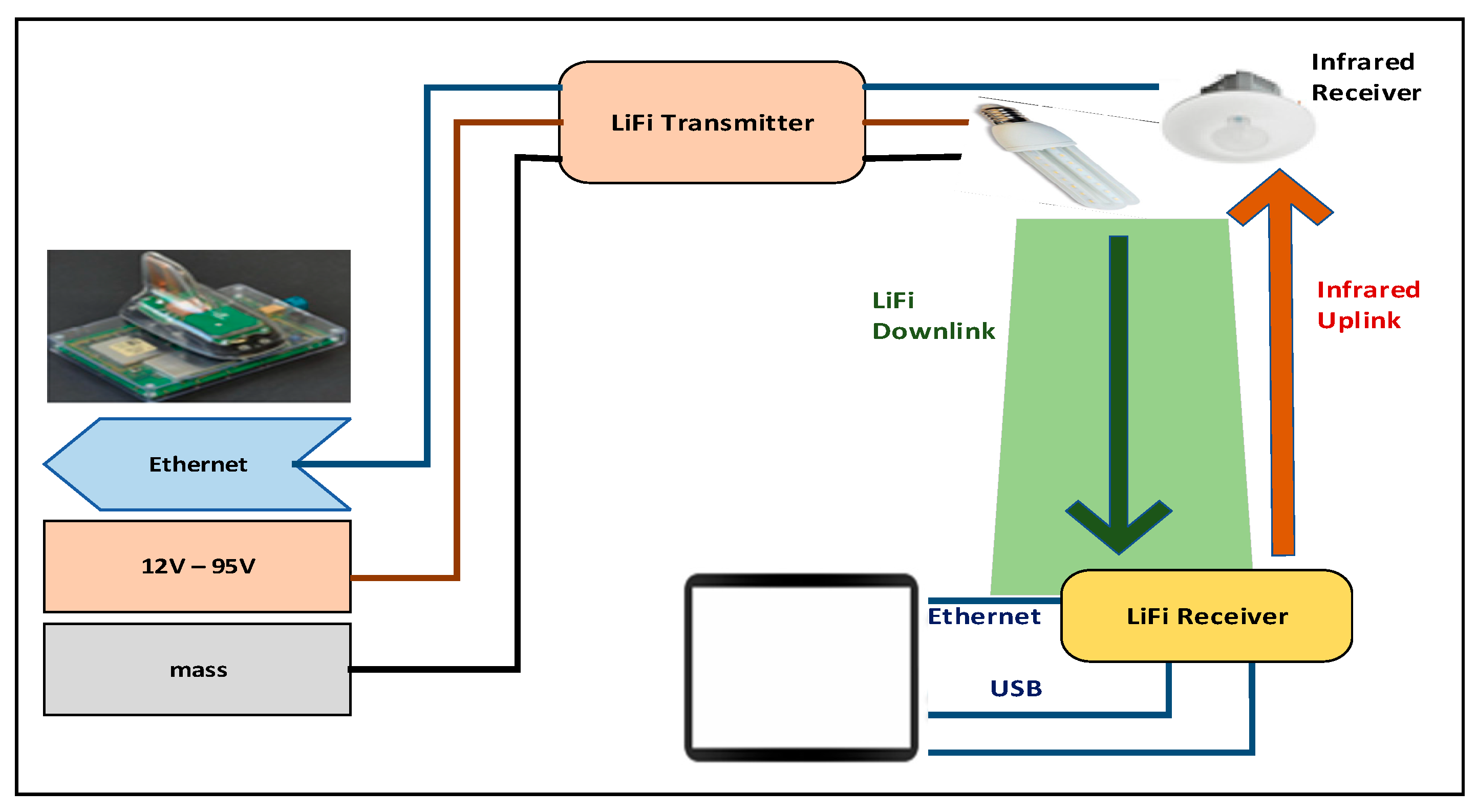
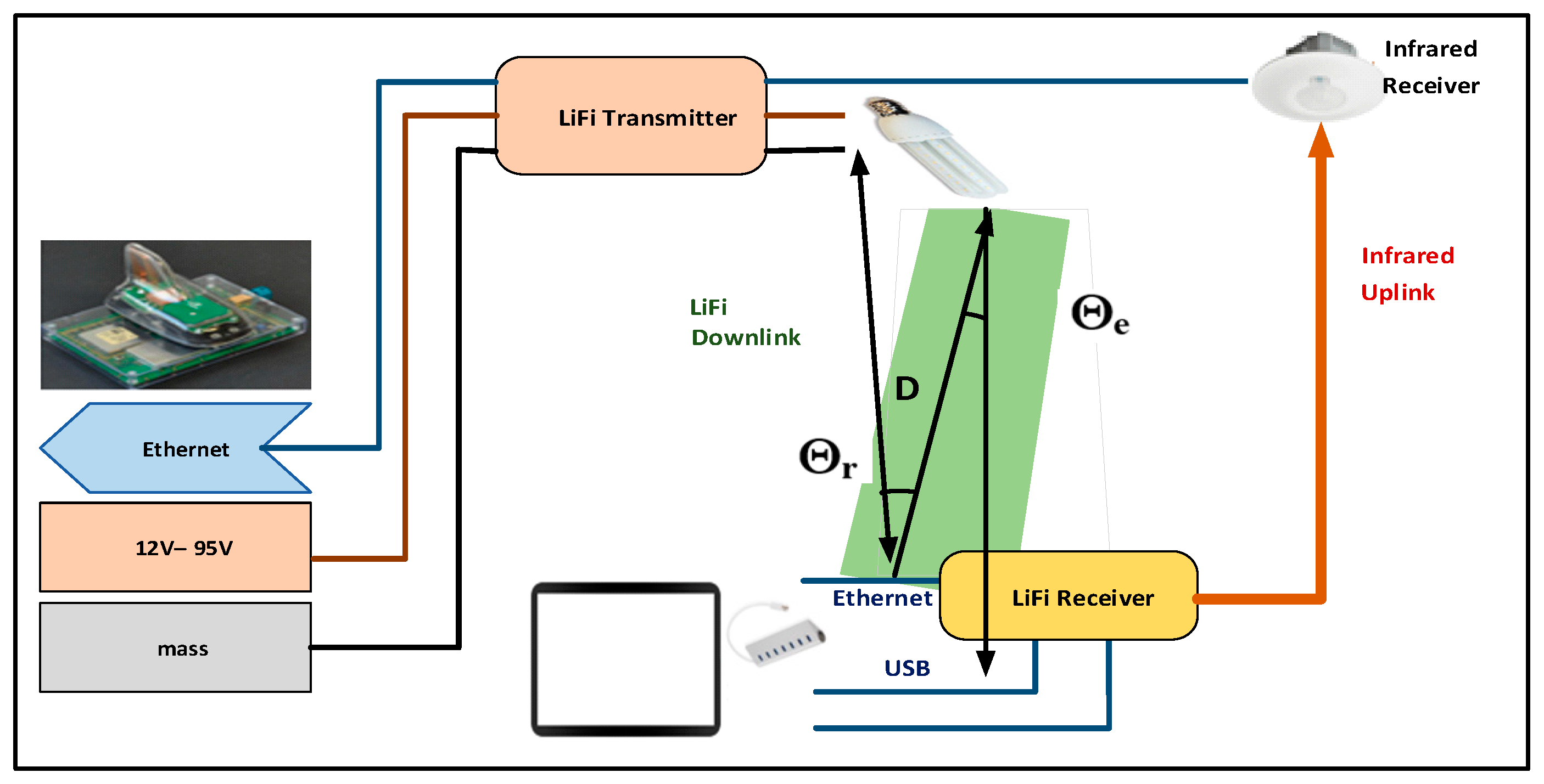
The functional diagram of
Figure 6 presents the different parts of our LiFi intra-vehicular communication system.
Powered by a DC current of 12V to 95V, the LiFi transmitter modulates the data from the Smart Antenna via an Ethernet cable; it then controls a LED (Nichia LED installed in PSA reading light) which lights on and off at a preset frequency. The modulated data in binary format is transmitted according to the flashing speed of the LED. A LiFi receiver is installed in the illumination area of the LED in order to receive and reconstruct the data. The first is powered using two USB cables linked to the mobile device. Data transmission between the receiver and the mobile device is done via Ethernet.
For security reason, the PSA Smart Antenna could not be moved outside the PSA office site. For this reason, it becomes necessary to first model a web server in LISV laboratory by encapsulating the audio/video data and implement it in a Raspberry Pi 3 card. Once the LiFi module works well with the Raspberry Pi 3, actual tests could be done using the Smart Antenna.
The module used in this project is developed by OLEDCOMM for hospital application, allowing internet access to computers using LEDs of more than 20W. To integrate it into this application, a less powerful LED (PSA reader) of 500 mW, instead of 20 W must be used, along with mobile devices, such as tablets or smartphones. Once the module becomes functional, this demonstrator is evaluated using all parameters that affect its performance.
5.2. Modeling of Smart Antenna
A local web server that models the PSA Smart Antenna was developed, and was implemented in a Raspberry Pi 3 board, an ARM-based single-board nano-computer. The local web server was developed using EasyPHP. The web application itself is programmed using HTML, CSS, PHP, JavaScript, MySQL.
The chosen development environment is EasyPHP because of its features. EasyPHP is a Web development platform, allowing PHP scripts to run locally (without connecting to an external server). EasyPHP is not in itself a software, but an environment comprising two servers (an Apache web server and a MySQL database server), a script interpreter (PHP), as well as an SQL administration component, phpMyAdmin. It has an administration interface to manage aliases (virtual folders available under Apache), and the start/stop of servers. It is possible to install everything necessary for the local development of PHP in one go. By default, the Apache server creates a local virtual domain name 127.0.0.1 or localhost. Thus, when choosing “Local Web” in the EasyPHP menu, the browser opens on this URL and displays the index.php page of this site which in fact corresponds to the content of the EasyPHP “www” folder.
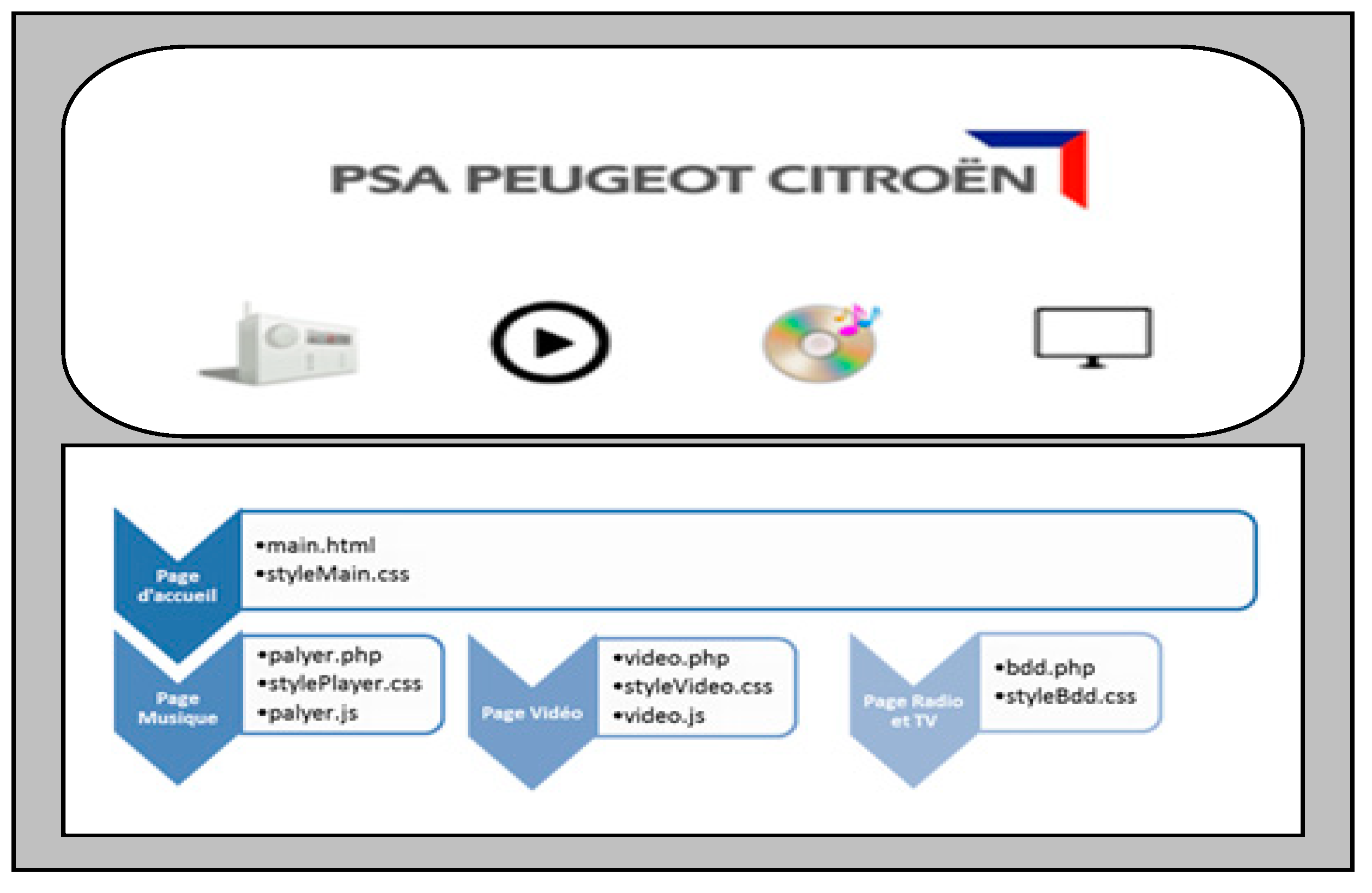
For this application, the content and aesthetics of the server were defined. Four menus (Radio, TV, Music, and Video) and a company logo appeared on the home page. See
Figure 7. When the “Radio” menu is selected, a submenu of three choices (FM, AM, RNT) is displayed. When one of the menus is clicked, another “Playlist” page opens up. If one of the playlists is clicked, the music or video starts. The webpage is programmed using the usual HTML language, along with CSS codes to render style to the webpage. This predefined part is called the static display. For dynamic display, the page content is based on the results of a database query. A database in which each element must have all the characteristics necessary to make a MySQL query was created using the SQL administration component, phpMyAdmin. The PHP language is then used to connect to the database, make some MySQL query and display its result, and finally to disconnect from the database. JavaScript is used for event management, i.e., start, pause, or stop a chosen music/video, adjusting the sound, or even the progress bar.
5.3. The Raspberry Pi 3 Component
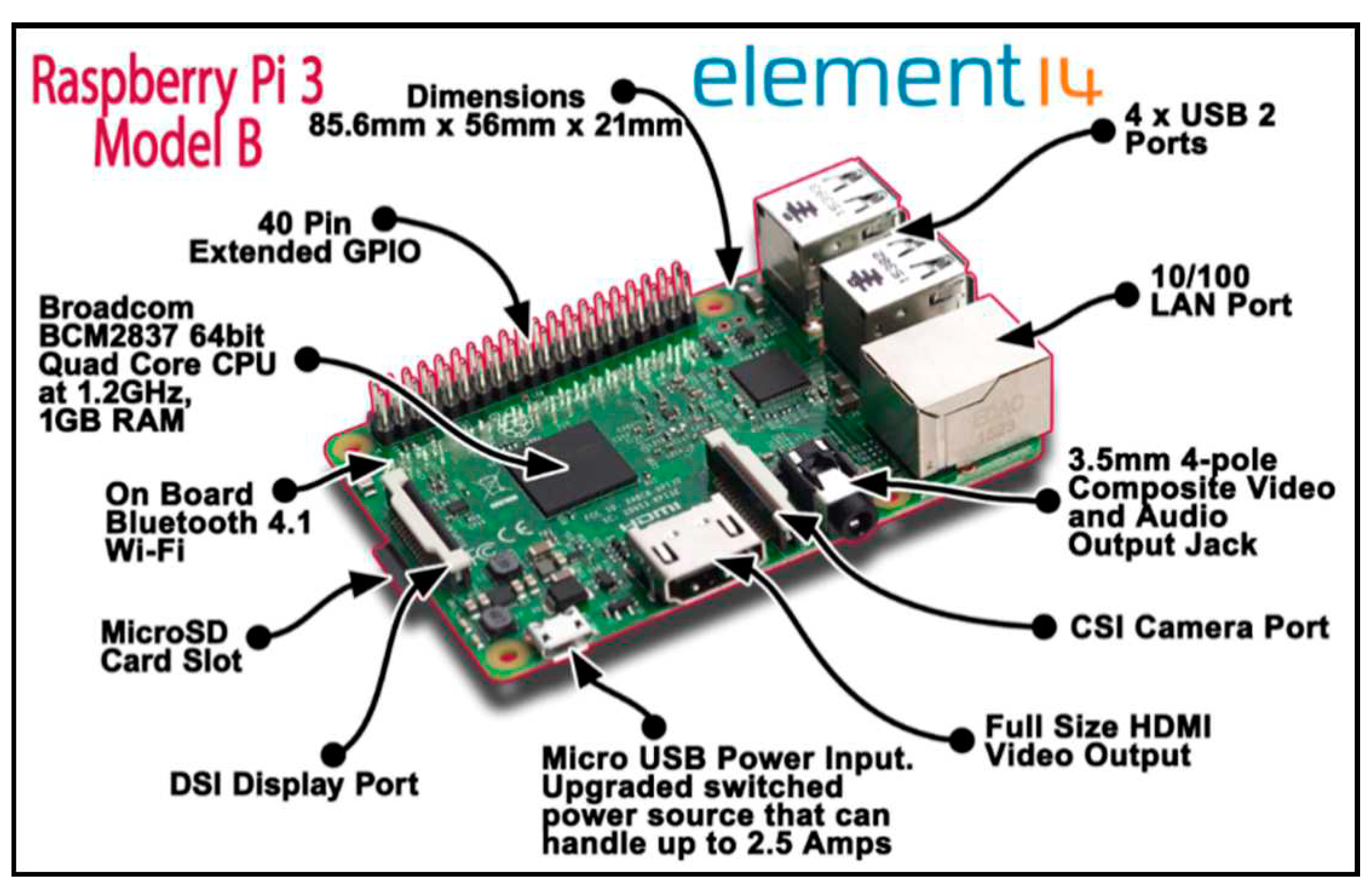
The Raspberry Pi, as shown in
Figure 8, is a single board nano-computer with an ARM processor. This computer, with the size of a credit card, allows the execution of several variants of the free operating system GNU/Linux and compatible software. Several models exist: Model A (A+), Model 1 B (B+), Model Zero, Model 2 B and Model 3 B released in February 2021. The one used in this project is the Raspberry Pi 3 Model B. It has a Broadcom BCM2837 64-bit quad-core ARM Cortex-A53 1.2 GHz processor and an integrated 802.11n WiFi and Bluetooth 4.1 chip. It has the same dimensions and connectors as the Pi 2 and B+64 models. The clock speed is 33% faster than the Pi 2, allowing for around 50-60% performance gain in 32-bit mode. In this work, the Raspberry Pi 3 is used as a web server. In terms of operating system, the Raspberry Pi Foundation recommends using Raspbian, a GNU/Linux distribution optimized for the Raspberry Pi hardware. Raspbian is based on Debian, embedding the LXDE desktop environment and the Midori web browser.
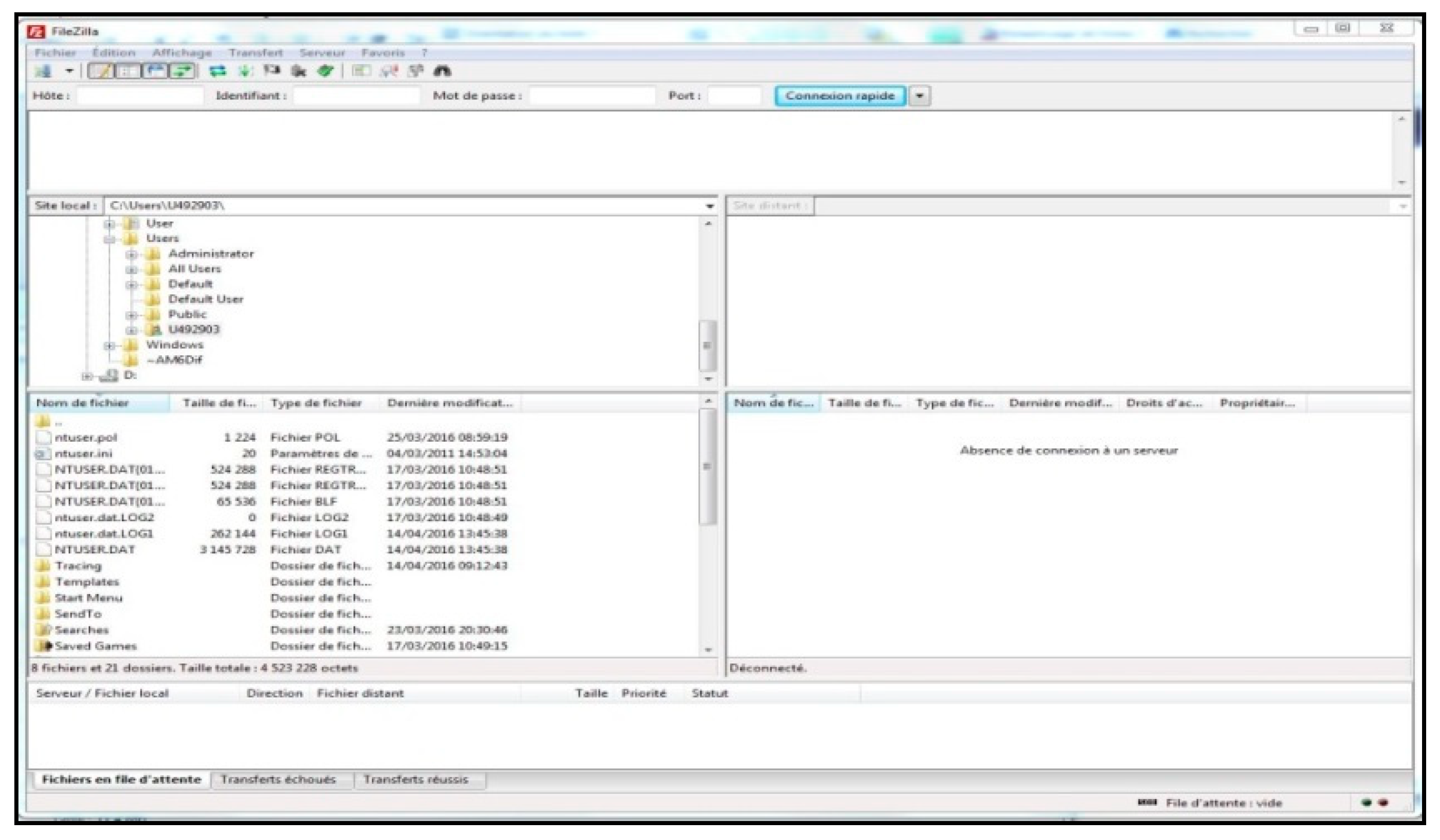
Once the necessary web servers were installed, the previously developed server has to be integrated into the Raspberry Pi. Two approaches are possible:
The local IP address defined by default by the Apache server is 127.0.0.1, while the address of the Smart Antenna is 10.6.5.101, so the server IP address must be changed. Doing that, the local server becomes functional.
5.4. Integration of LiFi Module in the Intra-Vehicle Communication
After finishing the modeling part of the Smart Antenna, the integration of the LiFi module of OLEDCOMM in the intra-vehicle communication is implemented next. As shown in
Figure 6, the LiFi diagram in our application, the LiFi module developed by OLEDCOMM integrates with the PSA reader and different types of mobile devices.
The data transmission between the LiFi receiver and the mobile devices is done by Ethernet. In order to test compatibility with different types of devices, four tablets of different brand are used: the Samsung Galaxy Note 10.1, the Huawei M2, the iPad Pro and the Microsoft Surface 3 as well as a Huawei smartphone. However, the Samsung Galaxy Note 10.1, Huawei M2 tablets and the Huawei smartphone did not have a driver capable of supporting the Ethernet connection. There were also independently developed drivers for accessing Ethernet using an Ethernet-Mini USB adapter, but this was only suitable for dedicated applications. On the other hand, the iPad Pro and the Surface 3 have the Ethernet connection.
5.4.1. Integration of a Nomad Device – Ipad Pro
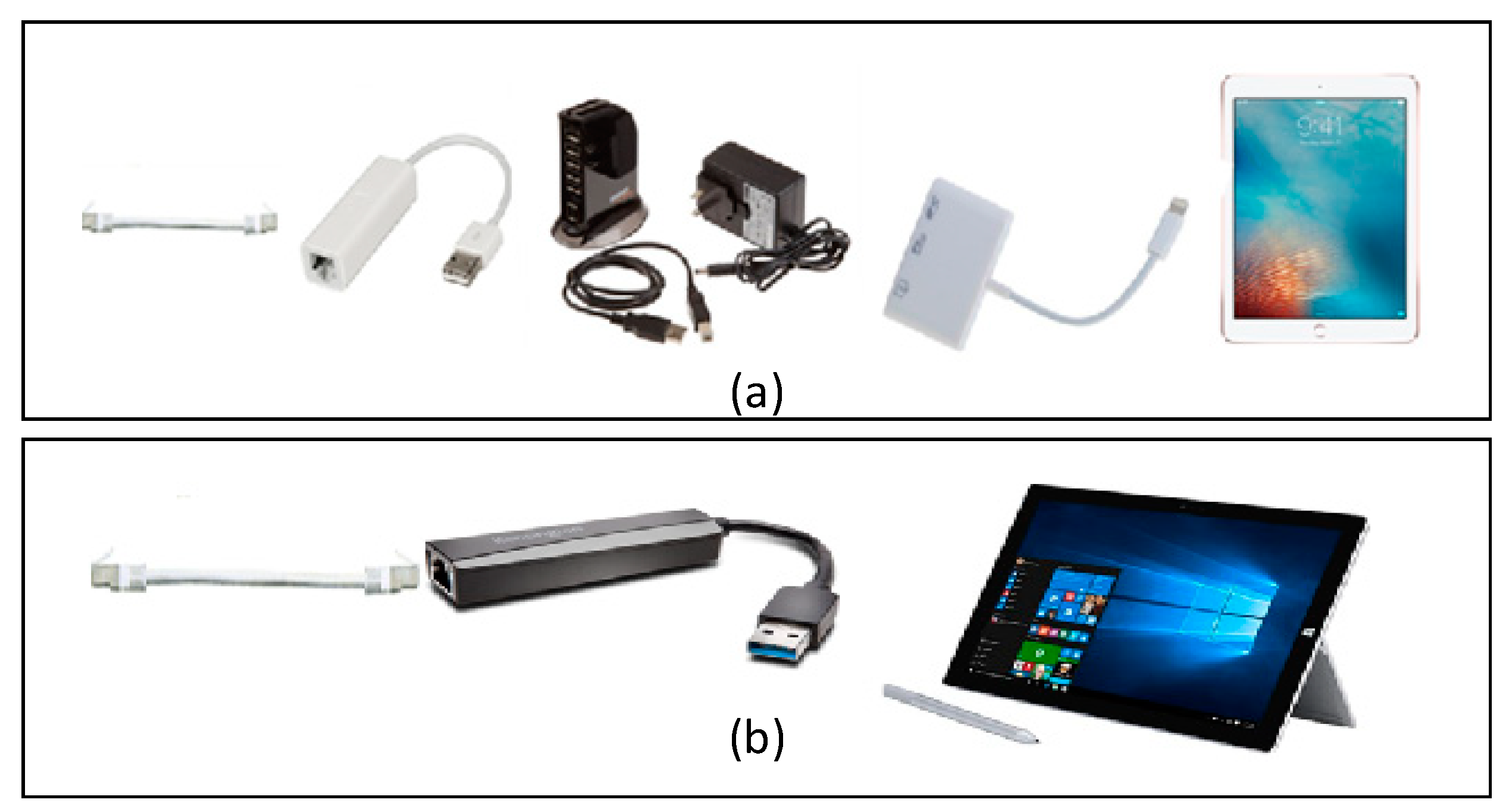
Access to Ethernet for iPad was not so simple. See
Figure 10a. There was the Ethernet driver in the IOS 9 system, but there was no Ethernet – Lightning adapter (power socket for new Apple brand devices). Here are the hardware needed to connect the iPad to Ethernet: (i) Lightning to USB Camera Adapter, (ii) USB-Ethernet adapter, (iii) USB power socket (powered at 220 V and a USB type B - USB type A cable), and (iv) Ethernet cable. It should be noted that the USB Hub is essential to power the Ethernet-USB adapter. On the other hand, the USB Hub had to be powered at 220V, which is impossible in a vehicle. Moreover, the receiver of the LiFi module is powered by two USB cables. This can be easily managed by a USB Hub.
5.4.2. Integration of a Nomad Device – Microsoft Surface 3
Unlike the iPad, the Surface 3 only needs an Ethernet–USB adapter to have the Ethernet connection, because it has by default a USB interface and a driver allowing Ethernet access. See
Figure 10b.
To conclude this sub-section, the module is only compatible with certain mobile devices such as the iPad Pro and the Surface 3. And in this application, given the power supply constraint in a vehicle, the iPad Pro is not embeddable. It may also be compatible with some devices that have not been tested. Given the advancement in LiFi technology, it is very likely that major smartphone and tablet device vendors will integrate a LiFi chip within them in the future. The purpose of this application is above all to make a first demonstrator.
5.5. Integration of the PSA Reader
With the arrival of the LiFi module, it became possible to integrate the PSA reader into the LiFi module. A Citroën C4 Picasso car was chosen to set up the demonstrator. The LED to be integrated is therefore a reading light (composed of an LED, two resistors and an optic) used in the C4 Picasso. This LED is provided by Nichia.
In this part, the specifications of the reading light as well as that of the LED and the work that was carried out are presented. The integration part of the reader makes it possible to test hypotheses, analyze the results, and see if the changes made to the system have been useful. The process repeatedly comes down to analyzing the result and identifying the problem. The work will be presented in the next paragraphs. Only representative measurements will be taken to simplify the analysis of the result.
5.5.1. The Reader’s Specification
Here are the electric specifications of the reader:
Power supply under 13.5 V
Switching position 1: closed circuit AND power supply with +BSI signal
Switching position 2: closed circuit AND power supply with +ACC signal
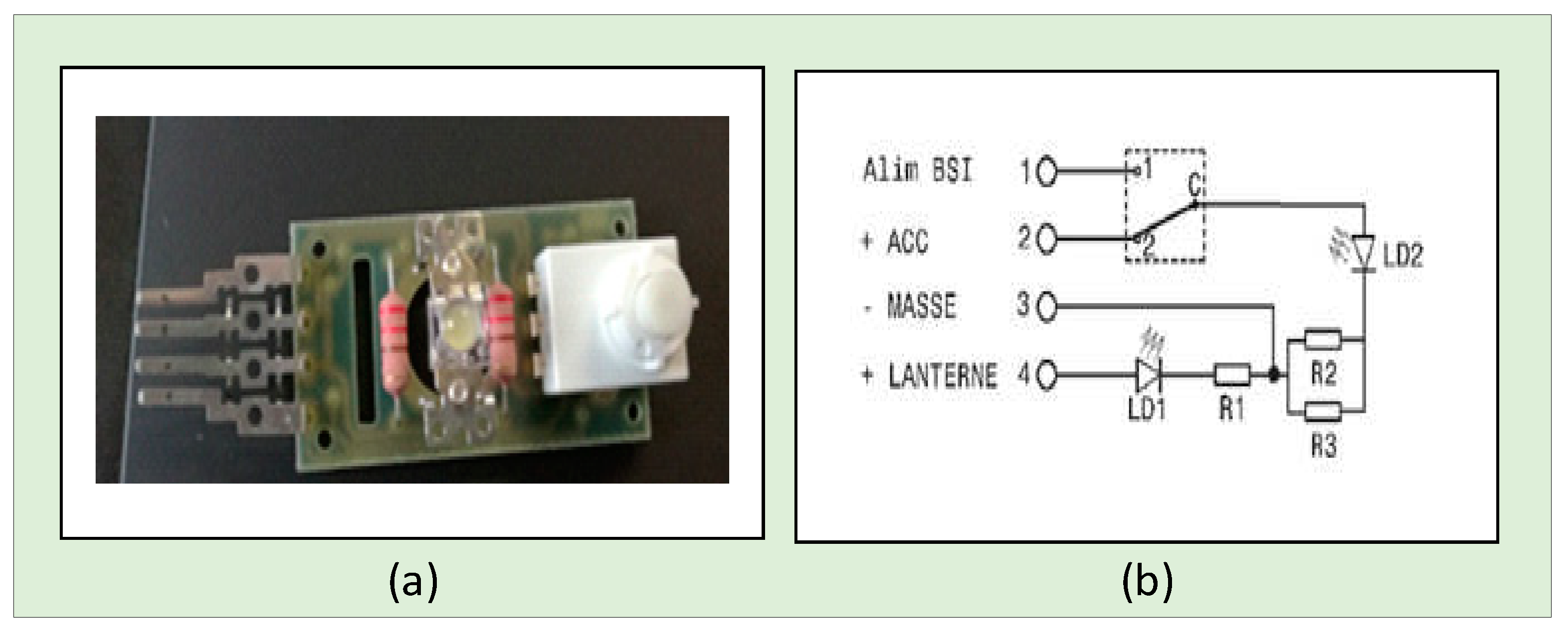
When the reader is supplied with 13.5 V on +ACC and ground, LD2 lights up. The PSA e-reader without housing (case) is shown in
Figure 11a while the electric diagram of the e-reader is shown in
Figure 11b. See
Appendix A for further details.
5.5.2. The Nichia LED Specifications
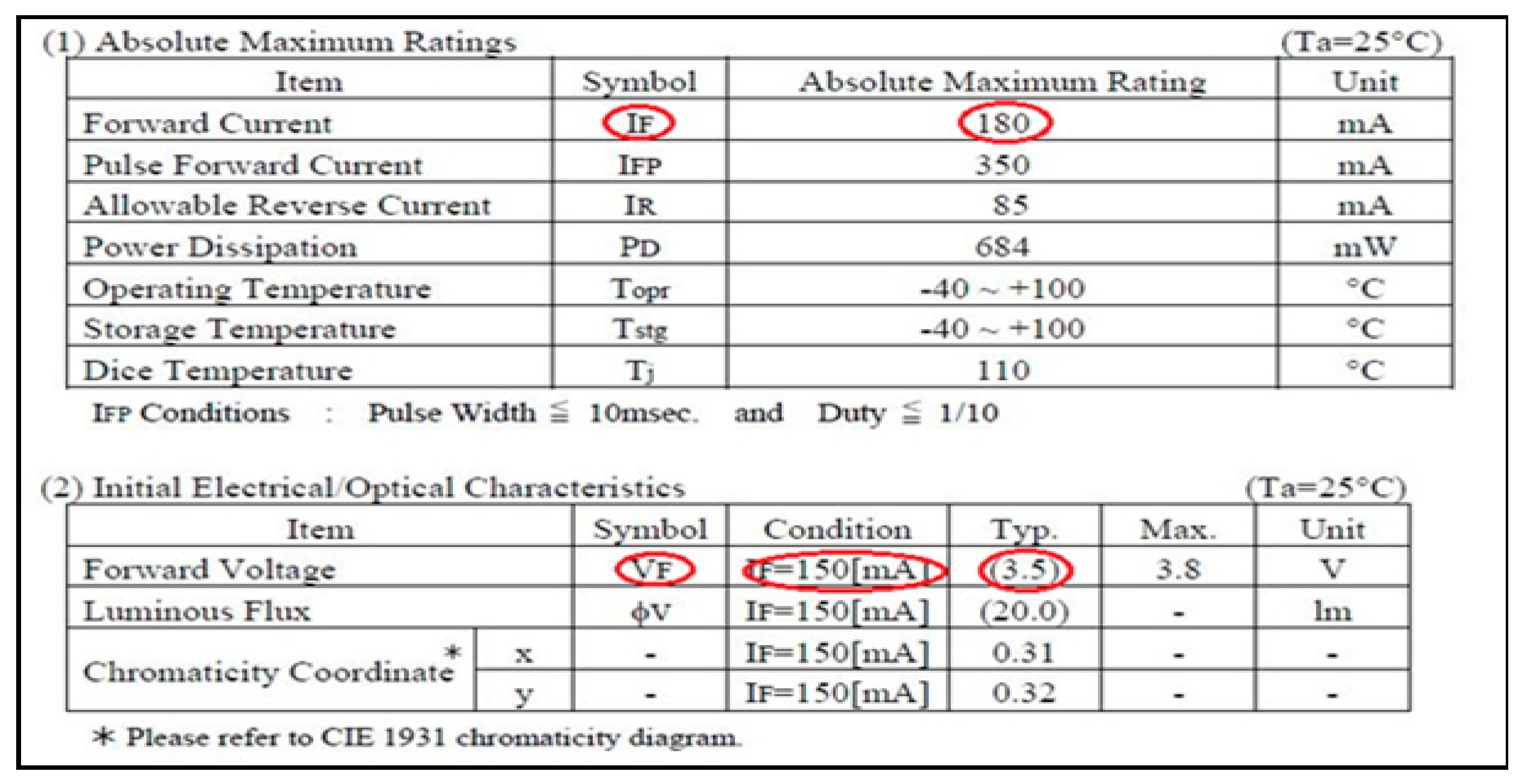
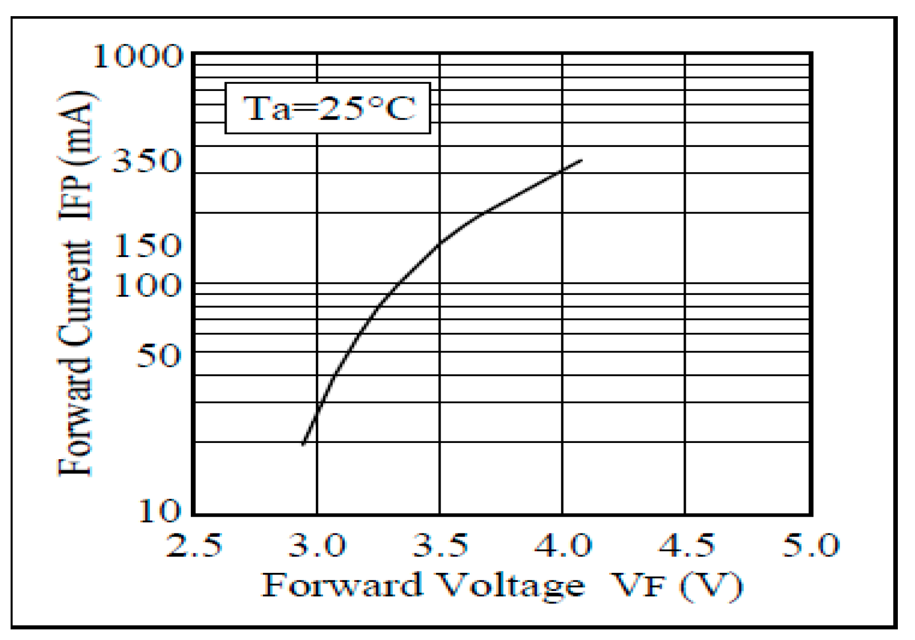
The specification of the LED (see
Figure 12) in this application is given below:
Forward Current (Absolute Maximum Rating) IF: 180 mA
Forward Voltage (IFc = 150 mA) typical VFt: 3,5 V
Forward Voltage (IFc = 150 mA) maximal VFm : 3,8 V
5.6. The Voltage Regulator
The first problem to consider during integration is the power supply of the LiFi receiver. As per specification, the power supply of the transmitter is 12V to 95V, while that of the reader is 13.5V. The power supplied inside the car is 13.5V. If the transmitter of the LiFi module is powered under 13.5V, the output of the transmitter, which will power the reading light, is approximately 9V according to measurements. It is therefore lower than the power supply required for the 13.5 V reader. This can influence the performance of the reader, in particular on the power of the LED and the illumination emitted. To solve this power problem, a voltage regulator (DC-DC converter) has been built into the transmitter, so the regulator settings need to be changed so that the transmitter output is 13.5V. OLEDCOMM modified the parameters of the regulator, obtaining the same output voltage as the input.
5.7. Evaluating the PSA Reader
The first test on the module was carried out by integrating the PSA reader for the transmission of data between the Internet and a Linux computer. It is also necessary to define the terms “downstream flow” and “upstream flow”:
Downstream rate: represents the information flow received from the antenna (internet, DTT, RNT, etc.)
Upstream rate: represents the flow of information sent by devices (tablets, smartphones, etc.) to the antenna.
Based on the measurements conducted, with a 13.5 V power supply, the current flowing through the LED was 0.13 A. There was no downlink throughput by LiFi, and from 8 Kb/s to 24 Kb/ s uplink by infrared.
5.7.1. First Connection
As stated, the original LiFi module of OLEDCOMM is intended for an application in a hospital. The LED used is 20 W, whereas according to the specifications of the Nichia LED:
Comparing this test with the one performed at OLEDCOMM, the most obvious difference was that the power of the Nichia LED (0.525 W in theory) is much lower than that of the LED used by OLEDCOMM (20 W). It is therefore the power of the LED to be studied first.
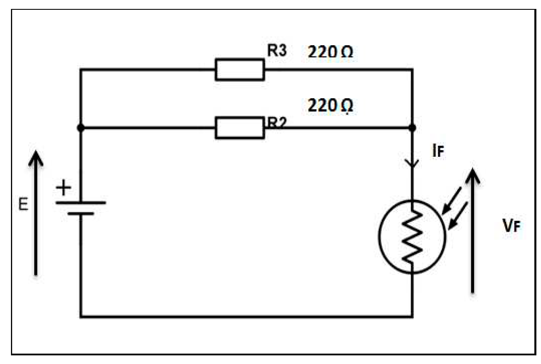
The electric circuit of the reader (see
Figure 13) is simply made up of two resistors in parallel and then with an LED in series, powered by a DC voltage. The current flowing through the LED can be increased by increasing the supply voltage, because IF= 2(E-VF)/R. As per the LED specifications, the maximum current that can flow through the LED at a fixed time (Pulse Forward Current) is 350 mA. The supply voltage can therefore be increased a little in order to improve the power of the LED, and thus to try to have a downward flow via LiFi.
A remarkable download rate of 200 Kb/s at a distance of less than 15 cm was noted, when the transmitter was powered at 15 V and the current flowing through the LED was 0.15 A. This result was not representative of a vehicle environment. However, it showed us the possibility of having a LiFi connection with the standard PSA reading light. The rest of the work was therefore to improve performance such as throughput and distance.
The intra-vehicle communication application implies a minimum speed of 5Mb/s for the RNT (Radio Numérique Terrestre or Digital Terrestrial Radio) to pass correctly. Regarding the distance, it takes at least 60 cm, which is approximately the distance between the roof of the vehicle and the knees of the passenger.
5.7.2. Receiver Modifications
The performance of the LiFi receiver mainly determines that of the LiFi system. They determine, on the one hand, the communication range, and the resistance against ambient light noise, on the other hand. The photosensitive elements of the receiver with high bandwidth offer the possibility of high-speed communication. Our studied photodetector is based on a photodiode, operating in photoconductor mode, which generates a current proportional to the incident light. The value of the photocurrent also depends on the spectral sensitivity of the photodiodes. Then, thanks to the amplifier mounted in transimpedance, the photoelectric current is transformed into a voltage. Digital filters are then applied to eliminate the noise and reconstruct the signal.
5.7.2.1. Changing the filter’s settings
As stated, the power of the Nicha LED is much lower than that of the LED used by OLEDCOMM, the emission flux is therefore much smaller, thus the SNR (signal-to-noise ratio) becomes greater. This can massively disrupt signal reconstruction on the receiver side. There is a need to modify the parameters of the high pass filters in order to eliminate ambient light as much as possible but retain as much of the light coming from the reading light as possible. That being said, it did not provide us any performance improvement.
5.7.2.2. Integration of a transimpedance circuit
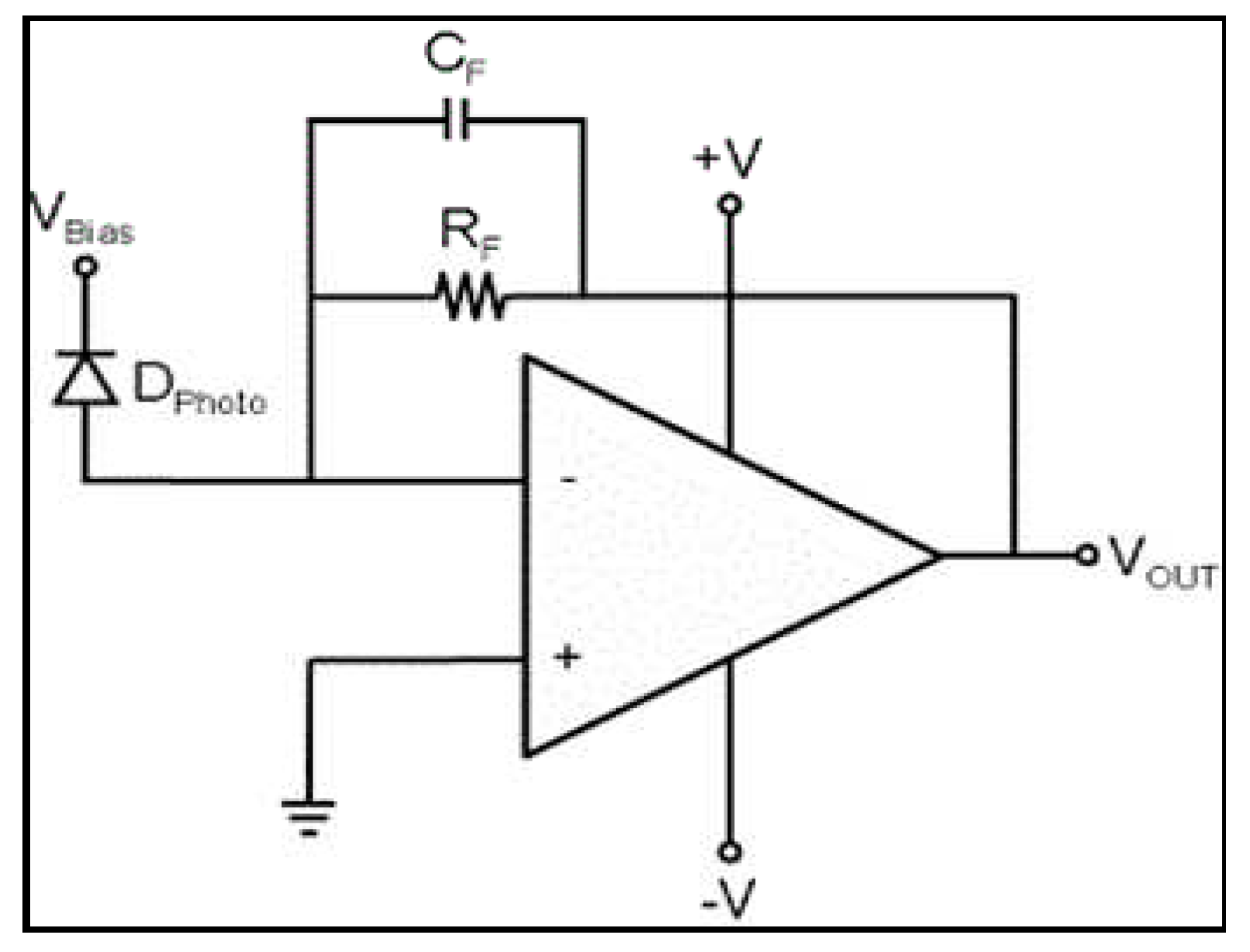
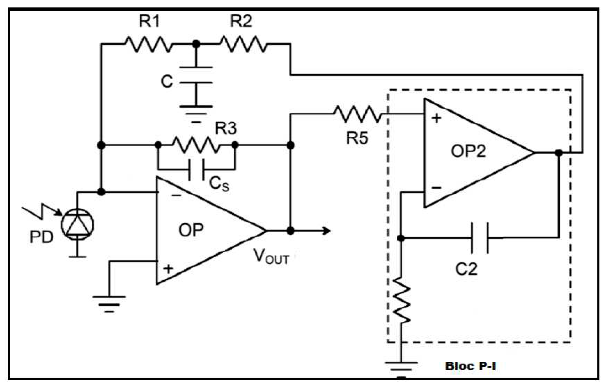
A test on the possibility of integrating a specific transimpedance circuit, published in a scientific article, into the receiver in order to improve the SNR was considered. Indeed, when the photodiode is illuminated by a beam of light, a photoelectric current is generated. In most applications, fluctuations in such current must be amplified and analyzed. The main problem with classic transimpedance (see
Appendix B) is that it creates a very strong shift caused by the addition of DC component. The circuit proposed in this article (see
Appendix B) makes it possible to automatically remove the offset (continuous component) of the output voltage so as to maximize the voltage oscillation of the alternating component while introducing the minimum possible electronic noise.
After studies on the performance of this circuit, it did indeed improve the SNR a lot. However, we noticed a bandwidth of 53 kHz which was lower than that of the classic circuit of 308 kHz. To conclude this part, despite the reduction in noise, this circuit cannot be integrated into the receiver because of its very low bandwidth.
5.7.2.3. Changing the preamplifier power supply
After analysis, we realized that another element which could influence the performance of the receiver came from the fact that the preamplifier was powered asymmetrically (+5 V by USB), whereas it would be more efficient to use a symmetrical +/-5 V (or +/-12 V) power supply, which, in the case of automobiles, can only be manufactured from 12 V batteries. This would involve quite bulky voltage regulators. Modifying the preamplifier circuit is therefore a possible approach but not a priority. It is also possible to add an optical filter before the photodiode, but given the time and cost constraints, this is a feasible option.
5.7.2.4. Increased sensitivity of the photodiode
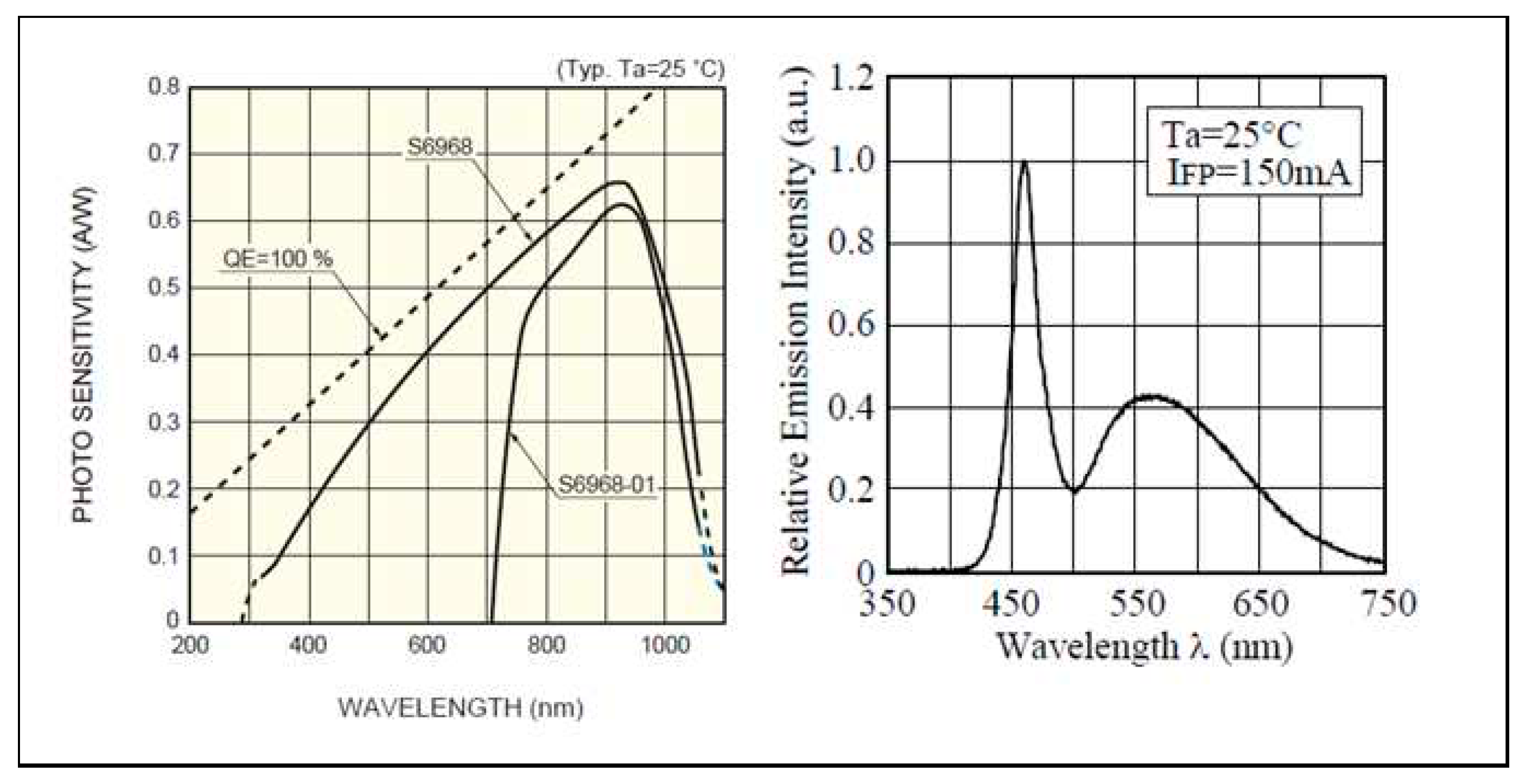
Another element which depends on the value of the photocurrent is the spectral sensitivity of the photodiode (see
Figure 14). The reception principle consists of converging the maximum amount of radiation onto the photodiode using a large lens. This photodiode, which must be as sensitive as possible, ensures the direct conversion of the energy received in the form of a modulated current. This signal can then be processed by a chain of low-noise amplifier stages.
We then studied the photodiode. Indeed, the photodiode used in the LiFi module is ES S6968, which is more sensitive to red light, while the light emitted by the PSA reading light (see
Figure 13) is closer to blue. This meant that little useful light was captured by the photodiode. It is therefore necessary to use a photodiode more sensitive to blue light. According to our research, almost all existing photodiodes on the market are Silicon photodiodes so they all have almost the same spectral sensitivity, which showed us that there was no better choice.
5.7.2.5. Increase in the receiving surface of the photodiode
Increasing the receiving surface of the photodiode, however, would make it possible to capture more light. On the other hand, it could also increase the capacity of the circuit, thus reducing the bandwidth. We still tried with another photodiode of larger size, making a compromise between the amount of light captured and the bandwidth. The result showed us that the communication range was improved by up to 30 cm. However, the reception cone is smaller, and we had difficulty finding the operating point. Considering the fact that the user cannot take the devices in a fixed point in order to have a connection in a vehicle, it is then not possible to address this approach in our application. From the previous analysis and tests, we can conclude that changing the photodiode will not bring any improvement to the performance of the LiFi module.
5.7.3. Measurements and Analysis of the PSA Standard E-Reader
After conducting studies on the receiver, we find almost no approach that will improve the performance of the receiver in the application. We therefore carried out more in-depth studies on the e-reader, particularly in terms of electrical power and light illuminance.
5.7.3.1. Adding a lens
Adding a lens to the reading light would focus the emitted light, thus providing more optical flow upon reception. However, the focus point was very precise, which was not suitable for our application.
5.7.3.2. Electrical measurements and analysis of the e-reader
We then returned to the original problem: the electrical power of the LED. According to the specification, the power of the LED had to be at least 1.5 W for the LiFi module to work well. It is complicated to change the e-reader because the goal is to use LiFi on an already existing source to be able to analyze the adaptability of the system. However, we found a solution that could increase the power of the LED by studying the electrical diagram of the e-reader. See
Figure 15.
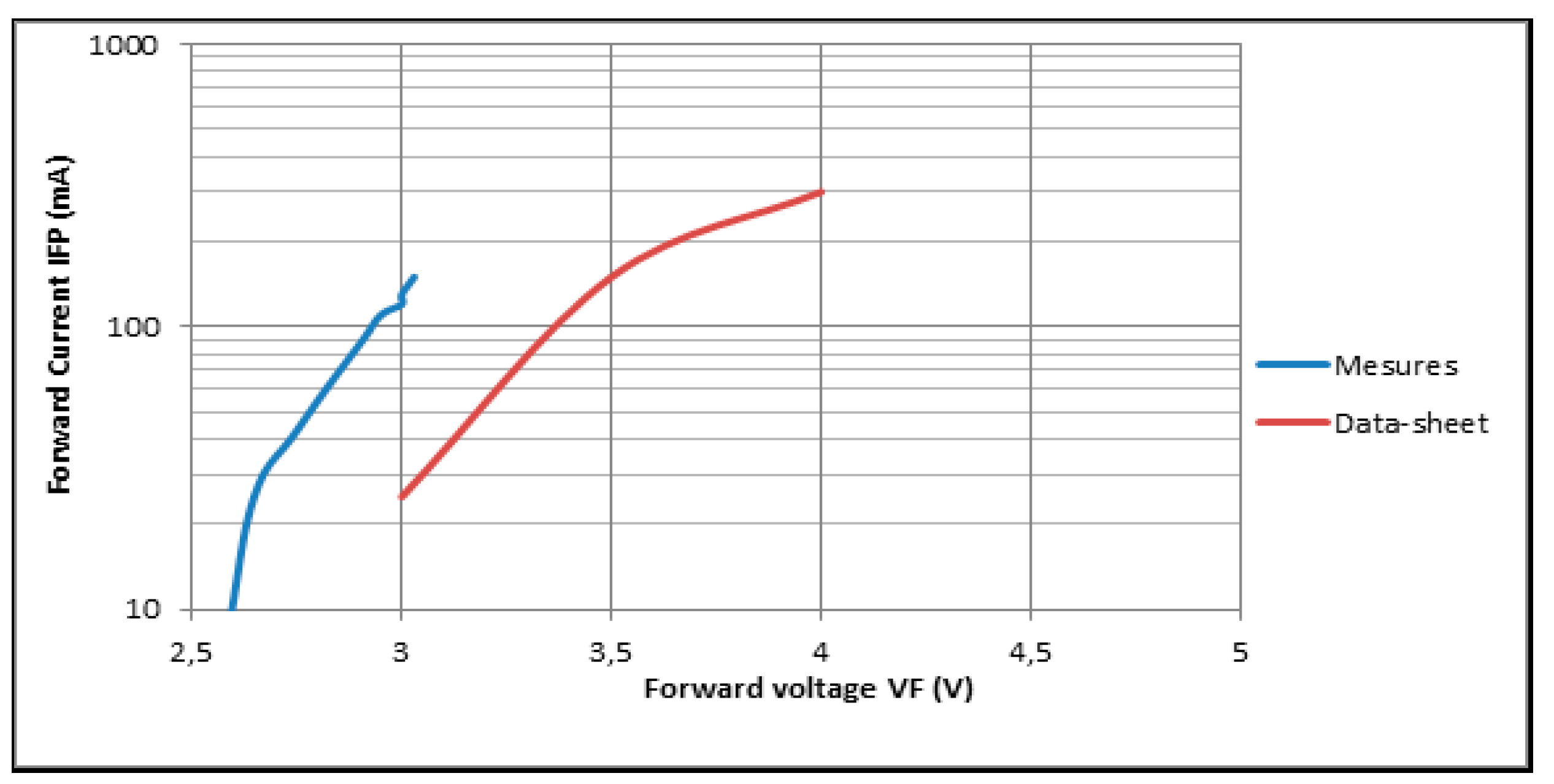
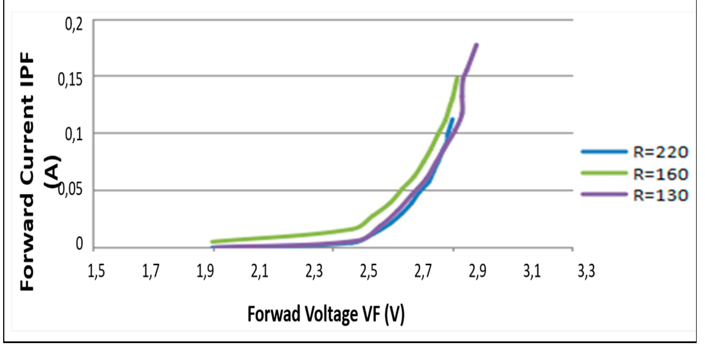
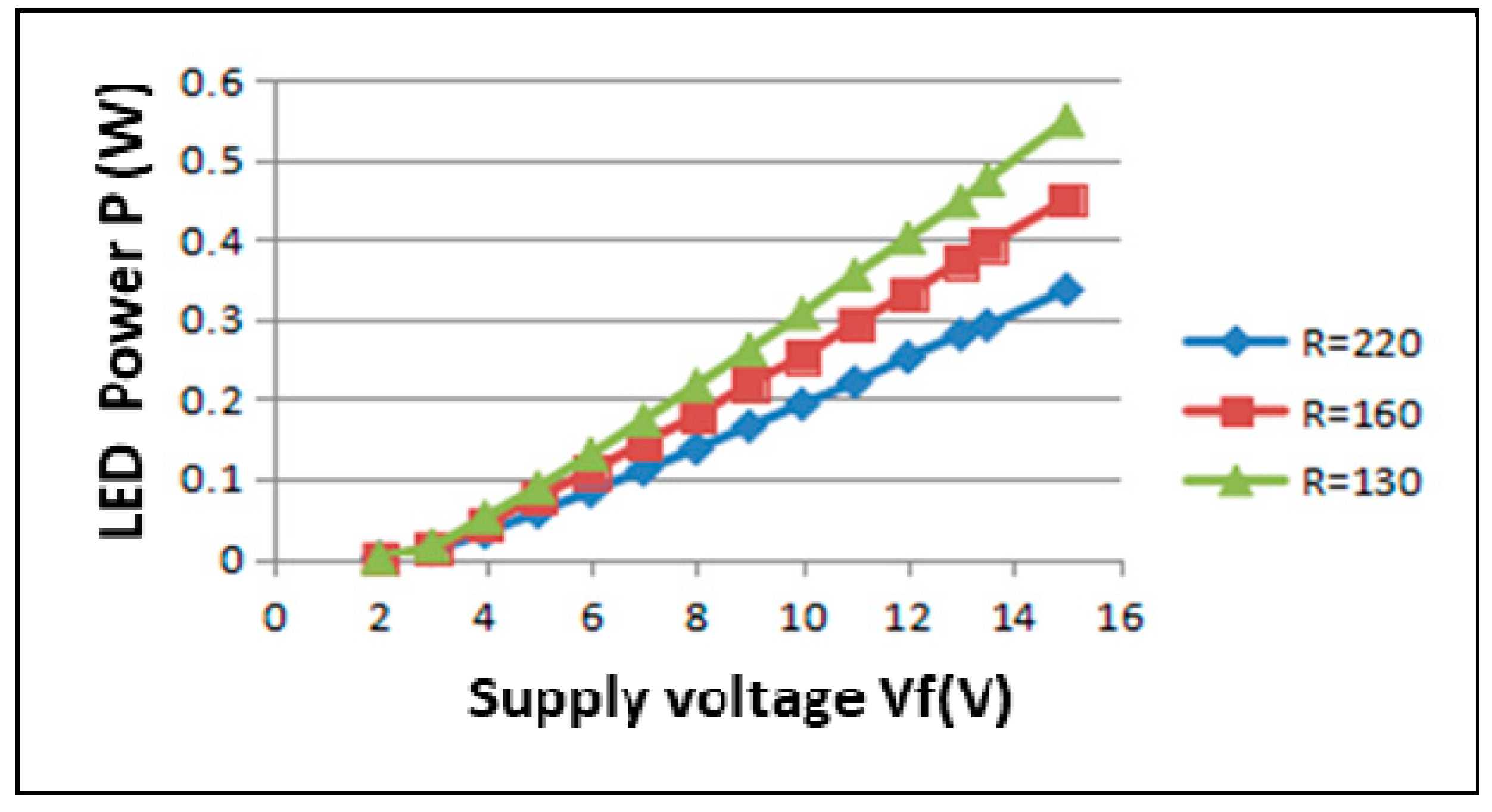
First, we studied the current-voltage characteristic of the original LED. We can notice that the current-voltage relationship does not correspond exactly to that in the specifications. The power was only 292 mW instead of the theoretical 525 mW. This could be caused by many things, including some issues during the manufacturing of the LED. Moreover, according to these measurements, the voltage across the VF LED varies between 2.7 V and 3 V. The current passing through the IF LED increases by decreasing the value of the resistors, the power of the LED thus increases following the increase in current. We decided to change the values of the two resistors to 160 Ω and 130 Ω. The measurements of the current-voltage characteristic (see
Figure 15) as well as the power-supply-voltage relationship (see
Figure 17) are illustrated below:
We noticed that the current-voltage relationship does not change by decreasing the resistance values, which is logical because it is the characteristic of the LED which has no relationship with the value of the resistance with which it is in series in the circuit.
The power of the LED, however, increases by decreasing the resistor values, up to 474 mW with two 130 ῼ resistors when the e-reader is powered at 13.5 V. This showed that the electrical power could be increased by reducing the resistor values, hence, the performance of the LiFi module could be improved.
Another test was then carried out using the modified e-reader with two 130Ω resistors, the result showed that there was very little improvement in communication range as there should have been in theory. This is analyzed below through measuring the optical characteristics.
5.7.3.3. Optical measurements and analyzes on the e-reader
Considering the fact that the photodiode transforms, in effect, the light flux that it detects into an electrical signal, the light illuminance at the position of the photodiode is more representative in relation to the electrical power. We decided to measure and analyze the e-reader from an optical point of view to explore the problem further.
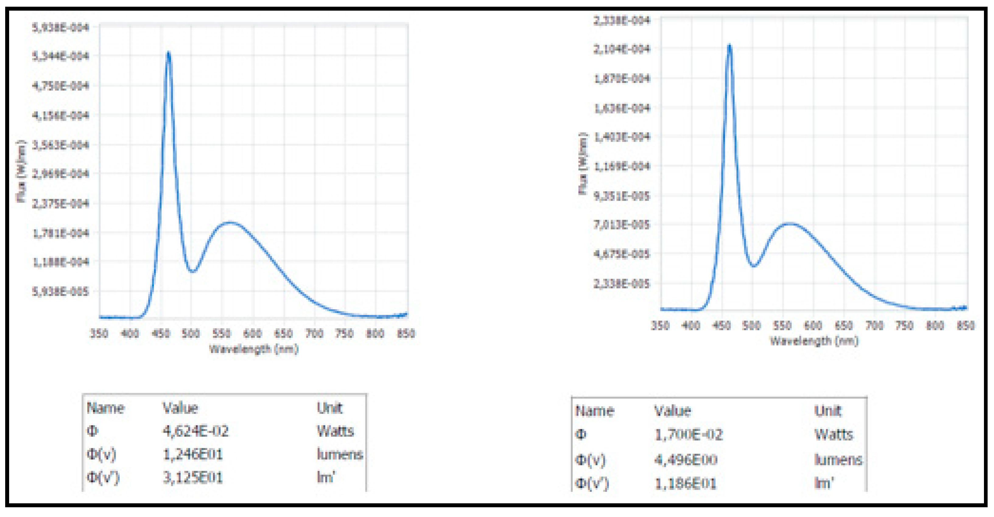
Firstly, the measurements of total flux and spectrum on the LED (with the original reader) were carried out with the integrating sphere (see
Figure 17) in order to compare with the data in the datasheet (see
Figure 13).
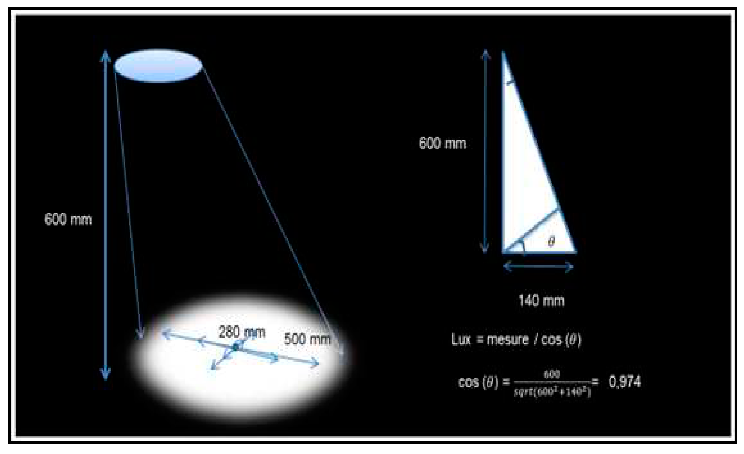
These measurements showed us that the LED complied with the datasheet in terms of spectrum. As per specification, a minimum of 55 lux is required for the module to operate in normal mode. According to the specifications, the functional lighting of the reading light, the illuminance (measured at 600 mm from the source):
Secondly, we carried out illuminance measurements at 600 mm from the source in order to confirm the values in the specifications. The test bench is illustrated in the figure below (see
Figure 19):
The e-reader was powered at 13.5V with a current of 0.098A. During the measurements, the reading light was fixed at the height of 600mm. The center was evaluated by the point which had the highest illuminance (in lux). For each diameter (280mm and 500mm), we made four groups of measurements in four directions (vertical and horizontal). In each group of measurements, we took four measurements in order to calculate the average.
As the light meter sensor has a diameter of approximately 30 mm, its surface cannot be neglected. The measured value has already been divided by the surface of the sensor (surface which receives the light), the actual lux in the vertical direction of the light is therefore the measured value/cos Ө. The final result was obtained by averaging the results of the four groups of measurements.
Some groups of measurements (see
Appendix C) were carried out on the original reading light with the housing/case and without housing/case, also the same measurements on the modified reading light (R= 130 Ω). The results are illustrated in
Table 2.
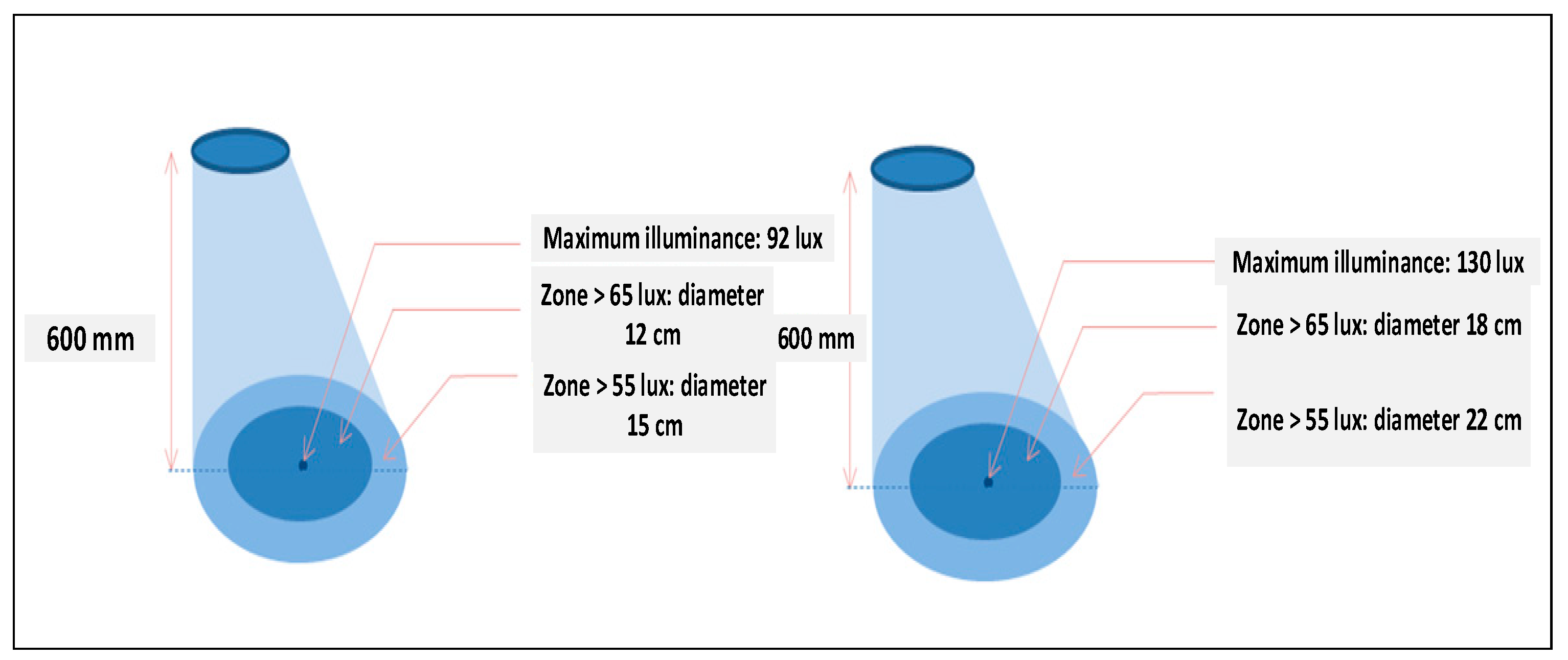
These measurements initially showed us that the illuminance in a diameter of 280 mm and 500 mm did not correspond exactly to what is in the specifications. During the measurements, we noticed that the light illuminance decreased very quickly as we moved away from the source. We therefore decided to take the next measurements on the original reading light in order to determine the zones where the illuminance is greater than 65 lux and 55 lux which should be the operating zones of the LiFi module according to the information.
The results (see
Figure 19) showed us that the e-reader did not comply with the illuminance level. The zones corresponding to the values of 65 lux and 55 lux are more restricted than those in the specifications. But the LiFi module should still work in the 150mm diameter area at a distance of 600mm from the source.
Confirmatory tests were then carried out at a distance of 600mm from the source. This showed us that the LiFi connection was not stable, even in areas where the illuminance was above 100 lux. After evaluation, we decided to use an older version of receiver that was larger but had better EMC (electromagnetic compatibility). With this new receiver, we had a LiFi download rate of 200 Kb/s to 300 Kb/s at a distance of 600 mm from the source.
6. Characterization of the Prototype
By trying all the solutions proposed previously, the performance finally improved a little. To establish the influence on the quality of communication to find the best configuration for maximum throughput, as well as a representative communication range, we decided to carry out high-level performance tests (throughput, distance, emission angle, reception angle, measurement condition, etc.).
6.1. Performance Tests
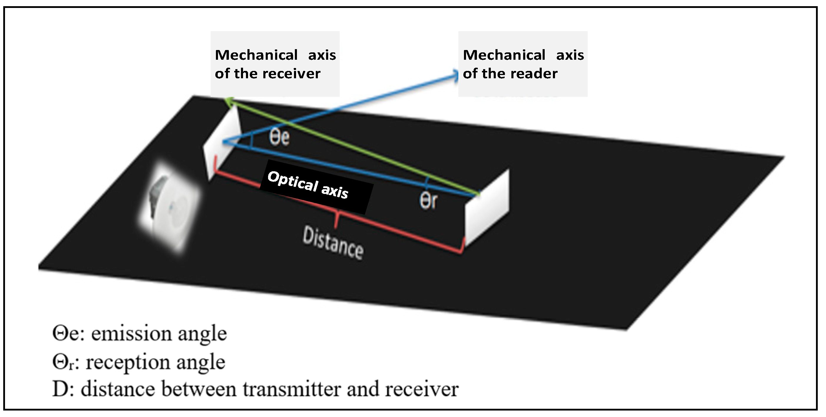
For each measurement, the following parameters were recorded: (i) Distance from source, (ii) Angles between transmitter and receiver, (iii) Brightness, (iv) Speed, and (v) Measurement conditions. The
Figure 21 below represents the measurement diagram:
A first group of measurements was carried out in the laboratory (see
Figure 22), with a closed white curtain, shaded sky. It should be stated that the emission and reception angle will be noted in the test plan, but it was ultimately not possible in practice due to a problem that occurred: it was difficult to find the operating point in order to have the LiFi connection every time the relative position between the e-reader and the receiver changed, even if the light illuminance is greater than 130 lux. Indeed, from subsequent error rate measurements, we noticed that when the reception angle changed, the error rate became very high, so it was difficult to find the connection while moving the receiver, especially the reception angle.
The results presented in
Table 3 show us that at a distance less than 600mm from the source, the speed is between 200 Kb/s and 300 Kb/s. When the distance varies from 600mm to 900mm, the throughput varies from 0 Kb/s to 200 Kb/s.
It was also necessary to do the same tests in the dark. See
Table 4. Furthermore, according to our optical measurements on the modified e-reader with a smaller resistor (R=130Ὼ), the illuminance is higher than for the original e-reader in the same position. It is therefore also interesting to make the same measurements with the modified e-reader.
From the results in the table above, we can also notice that there is little effect on throughput with the modified e-reader. Indeed, according to optical measurements subsequently, we noticed that the communication range was slightly improved up to 80 cm by having a speed of 200-300 Kb/s with the modified e-reader.
From the measurements carried out, we can conclude that the module is functional at a distance of less than 70 cm with the original e-reader and 80 cm with the modified e-reader with a throughput of 200-300 Kb/s.
6.2. BER Test Bench (Error Rate)
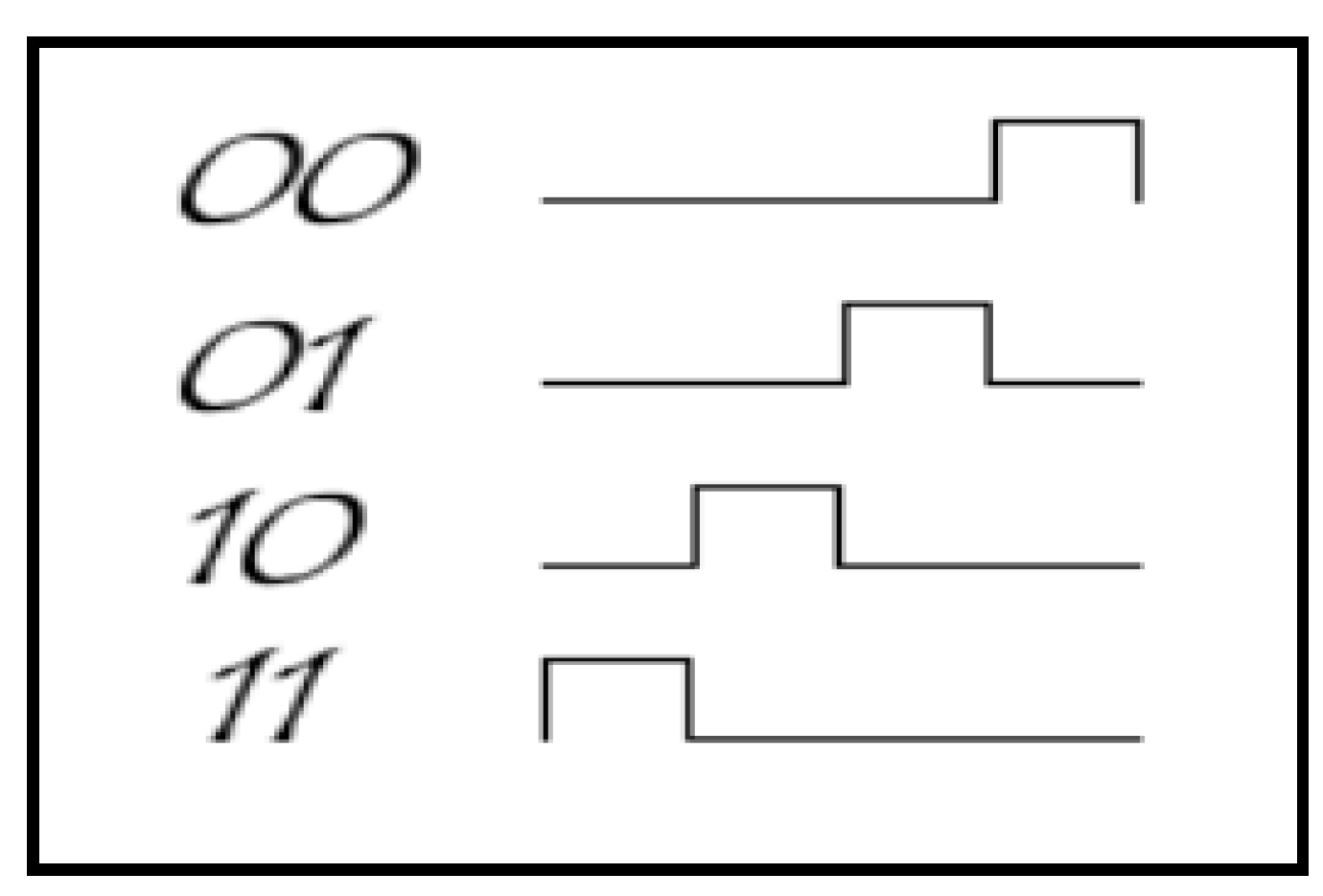
It must be noted that the LiFi module provided by OLEDCOMM uses 4-PPM (Pulse Position Modulation) coding. PPM modulation consists of transmitting pulses at constant amplitude and encoding the information according to the position of the pulse. A 4-PPM modulation allows 2 data bits to be encoded with 4 possible positions:
Figure 24.
Possible positions of 4-PPM coding.
Figure 24.
Possible positions of 4-PPM coding.
One of the difficulties in implementing this modulation technique is due to the fact that the receiver must be perfectly synchronized to adjust its clock at the start of each symbol. As a result, it is often implemented differentially, which means that the coding of each symbol is done relative to the previous one.
The advantage of this type of coding arises from the fact that this implementation is non-consistent. The receiver therefore does not need a phase-locked loop (PLL) to detect the phase of the carrier. This makes this modulation a good modulation technique for optical communications in which phase-coherent modulation and its detection are difficult to guarantee and very expensive.
The disadvantage of this modulation technique is its susceptibility to multipath interference on e-reader surfaces that can occur in the channels. The receiver thus receives several replicas at different times of each transmitted pulse. As the coding follows a differential logic of arrival times, it is very difficult or impossible to determine the correct position of the pulse which corresponds to the one transmitted.
As the SNR is quite large in our case, 4-PPM coding is probably not suitable for our application. It would be interesting to measure the error rate (BER: Bit Error Ratio) in order to analyze the influences of coding on performance, and possibly compare the different types of coding such as 4-PPM coding and Manchester.
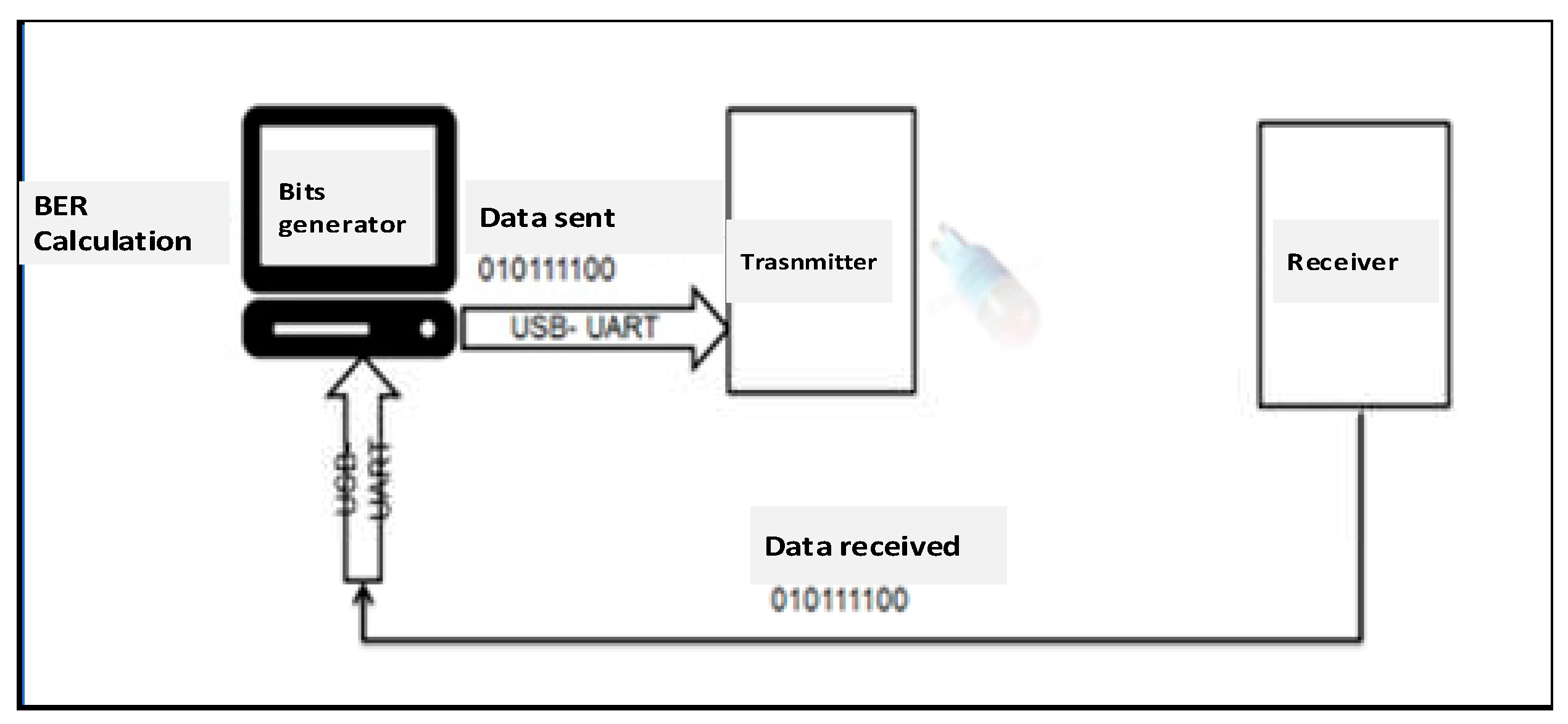
Since Ethernet-transmitter and receiver-mobile devices communication is done via Ethernet, it introduces errors due to the Ethernet link. To make the measured error rate truly due to LiFi communication, we used the UART-USB adapter provided by FTDI (Future Technology Devices International) instead of the Ethernet cable. A BER test bench was developed in C under Linux. The architecture of the bench is represented below. See
Figure 25.
6.2.1. UART-USB Interface
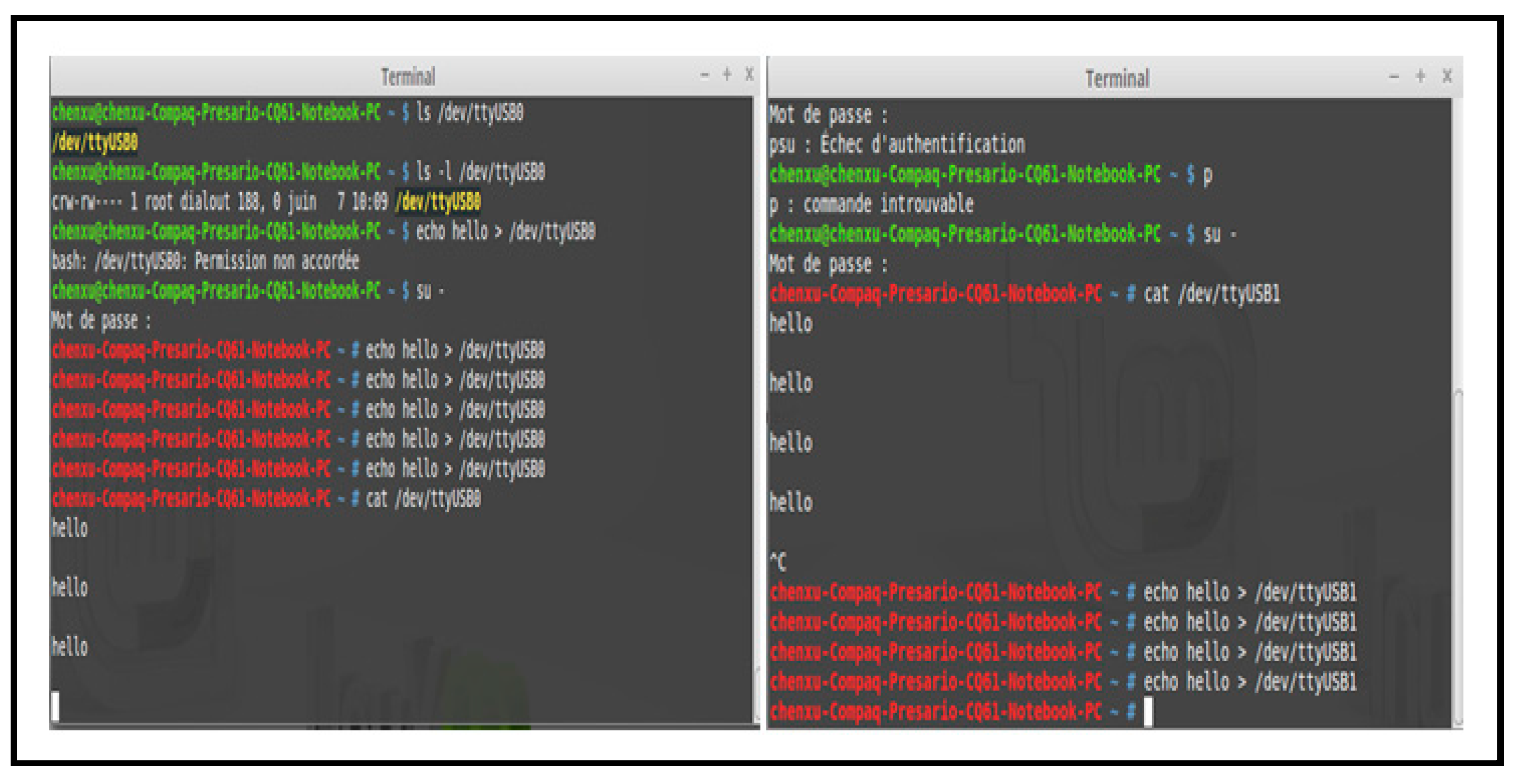
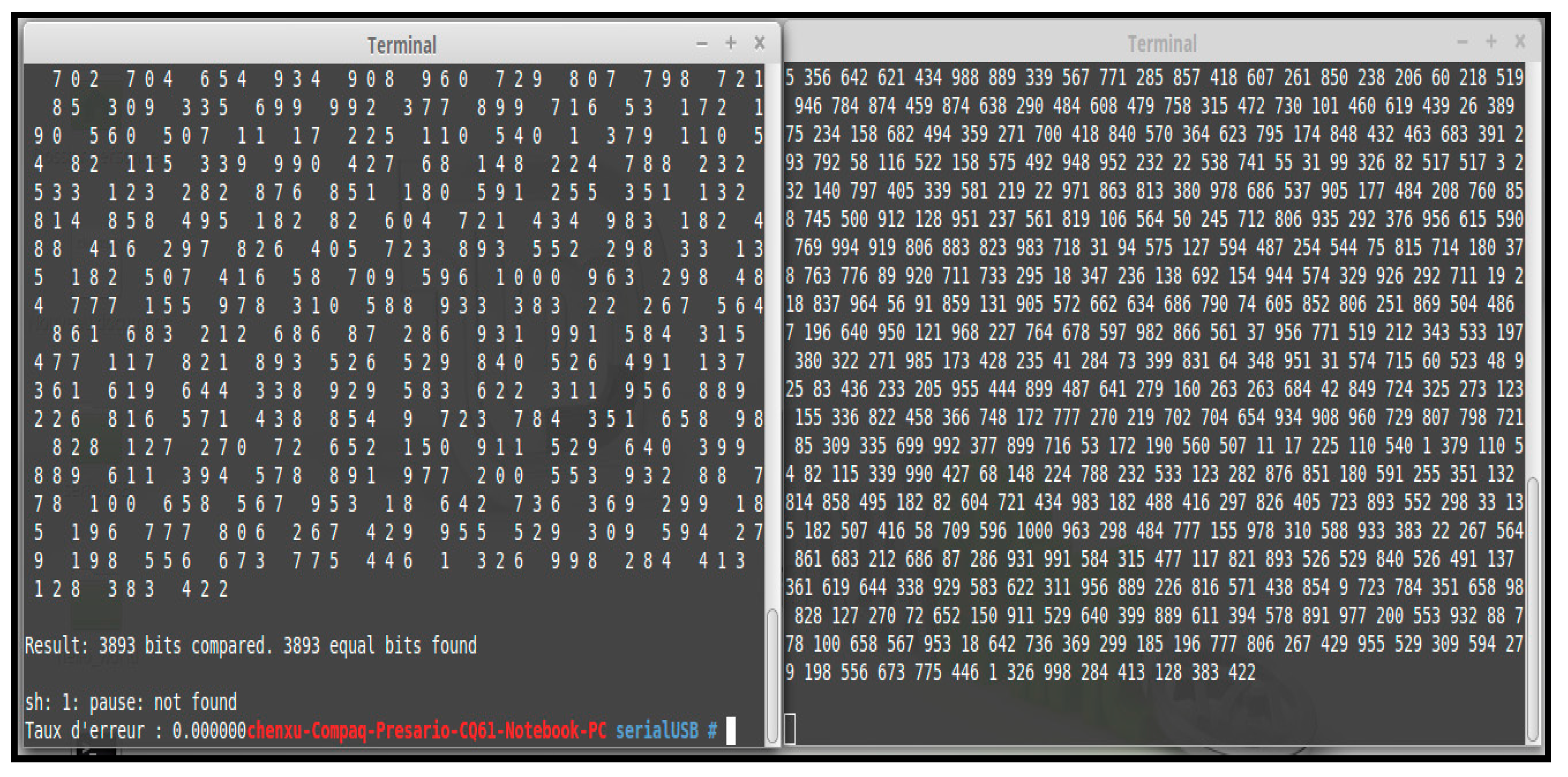
It was first necessary to ensure UART-USB communication between two adapters linked by wired connection instead of the LiFi connection on a Linux computer. The two FTDI adapters were recognized by computer as ttyUSB0 and ttyUSB1 interface. The sending of the message by these interfaces in console is done by the echo command, and the reception is done by the cat command.
Figure 26 represents the sending and receiving of data between the two FTDI adapters.
6.2.2. BER Test Bench Details
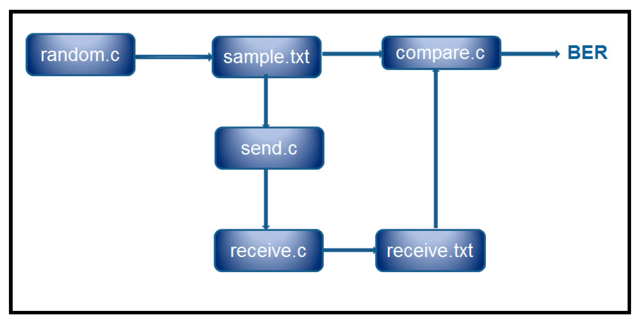
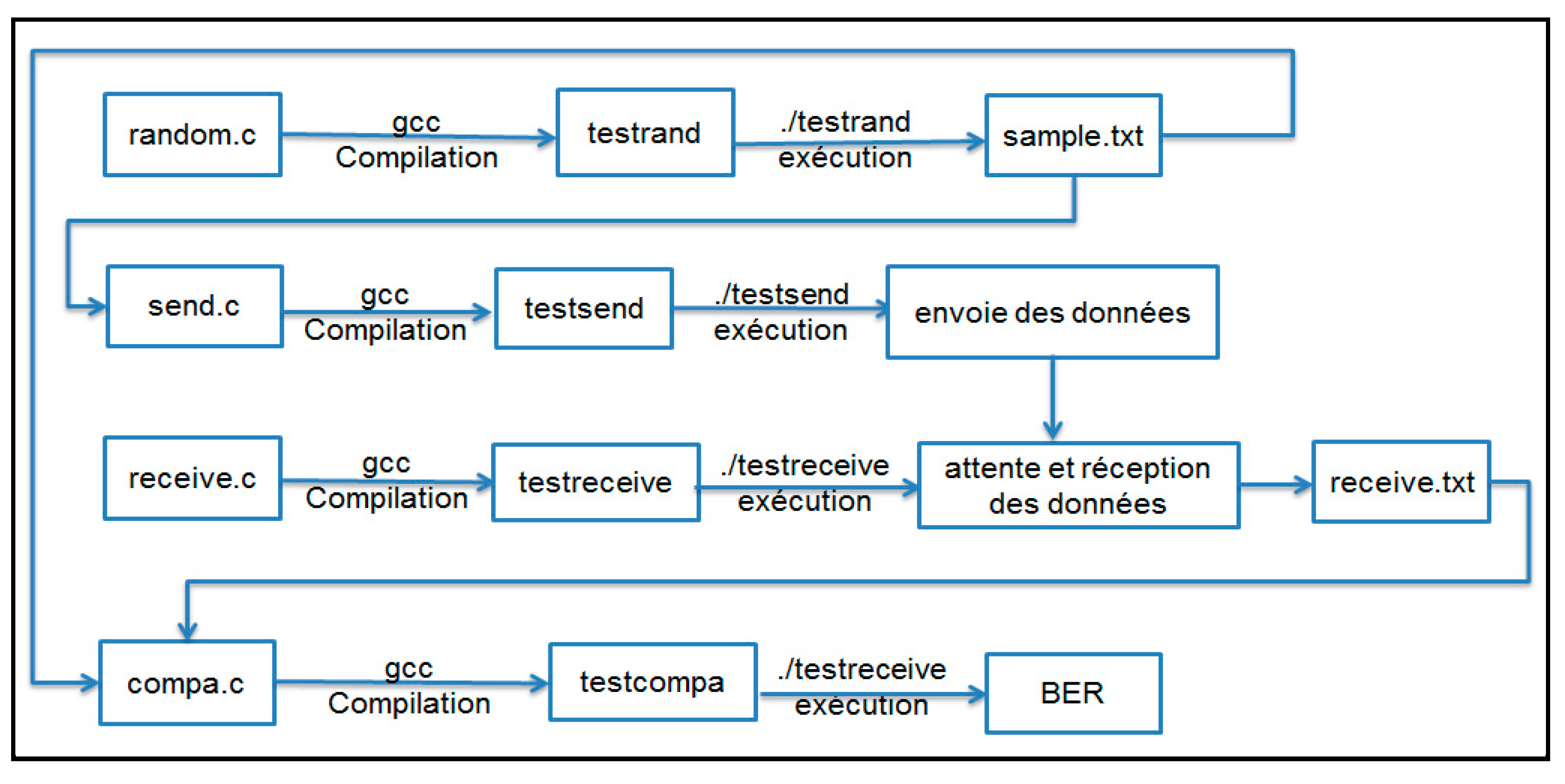
It was then necessary to develop the BER test bench to automatically generate the data and send it through one of the adapters, then receive it through the other, and finally calculate the BER. The program therefore consisted of five parts: (i) the bit generator, (ii) the UART communication setup, (iii) the sending of data, (iv) the receiving of data, and (v) the error rate calculator. The program architecture is represented by
Figure 27.
The random.c program allows us to automatically generate data whose quantity is defined by a variable. In other words, we can generate as much data as we want. The data is saved in a sample.txt file, then read by the send.c program and sent character by character via the properly configured ttyUSB0 port. On reception, the receive.c program allows you to receive the data coming from the configured ttyUSB1 port and save it in a receive.txt file which will subsequently be used to calculate the BER by compare.c.
Compilation is done using the installed gcc compiler, which allows the program to be compiled and the executable to be generated directly. Execution is then started with the
command ./executable_name. The compilation and execution chain in Linux is represented by
Figure 28. As this is done by wired connection, the error rate is 0.
Once the test bench was ready, BER tests were carried out following a test plan whose objectives were firstly to estimate the significant size of data to send. Second, to determine the relationship between the BER and the distance from the source. And finally, to find the acceptable operating zone for each distance.
According to initial tests at 30 cm at the center of illumination of the e-reader, two files of size 1.2 Mbits and 12 Mbits were chosen to measure the BER. Tests were then carried out at the illuminance center of the e-reader at a distance of 30 cm, 40 cm, 50 cm, 60 cm, and 70 cm to determine the relationship between light source distance and BER. The results (see Appendix D) showed us that the BER was lower, which was a very good order of magnitude for wireless communication. BER tests were also carried out to determine the acceptable zone at the distance of 60 cm which was in our specifications. The results showed us that the BER was lower than in a diameter area of 20 cm to 60 cm from the light source with the light of a lamp. Tests with the modified e-reader are to be carried out in order to study the improvement in performance. Other tests must also be carried out by changing the reception angle in order to study the mobility of the module.
To conclude this section, the module is functional at a distance of less than 70 cm with a throughput of 200-300 Kb/s. The communication range will be enough for intra-vehicle application. However, the speed of 200-300 Kb/s only allows low-definition videos to be played. Since April 2021, RNT has moved to HD (High Definition) which implies a speed of 10 Mbit/s, the speed therefore remains to be improved. The reception area is 20 cm in diameter at a distance of 60 cm due to the restricted illumination area of the e-reader. It will be better to also improve the reception area to be connected more easily.
7. Results and Discussion
Being a new technology, LiFi still has many technological challenges whether in the modulation method or in optical elements such as LED and photodiode. For example, the LED used in this project was not homogeneous, and the light received was not direct. This could make the SNR low, and signal reconstruction difficult. Also, the existing photodiodes on the market are Silicon photodiodes. This greatly limits the spectrum of light received. Additionally, it often requires a tradeoff between throughput and communication range. Moreover, LiFi is very sensitive to interference; noise filtering and signal reconstruction becomes essential yet very complex.
LiFi technology depends a lot on optical technology. The optical characteristics have significant influences on those of the LiFi system. Despite the challenges, we managed to carry out various measurements and technical analyses. In this way, we have come to achieving our goal of studying the feasibility of implementing LiFi technology in intra-vehicle communication. In order to improve the performance of the module in terms of throughput, communication range, or reception area, different avenues could be provided. Firstly, replacing the reading light with another lamp that is more powerful and better in optical characteristic can improve the communication range and reception area. Secondly, it will be interesting to test the symmetrical power supply for the preamplifier in order to have a better signal to reconstruct thus a better throughput. In practice, it is too bulky compared to our application, but we can always study its influence. We can also try using optical filters to eliminate noise as much as possible, thus improving throughput. In addition, the order of magnitude of BER shown by the tests for 4-PPM coding is quite good, but the area is very limited, it is also interesting to study Manchester coding or even O-OFDM. According to our research, an infrared part could be integrated in order to increase the flow rate. Moreover, we can continue to carry out tests to study performance and potential causes of problems in order to find other avenues for improvement.
8. Conclusion
In spite of all the challenges encountered throughout this project, this work is able to first, assess the maturity of LiFi technology, and second, to study in more depth the functioning of each part of the LiFi system in intra-vehicle communication, as well as configuring elements that can influence performance in the application. This project is a rediscovery of the world of automobiles and the new LiFi technology which relies on different areas of expertise, whether electronics or on-board systems or even optics.
This exercise demonstrates that there is always a difference between what we imagined and what really happened. This did not mean that things were not going well, it was in fact just a normal phenomenon that we had to accept. At the end of this study, we can conclude that the prototype module is functional at a distance of less than 70 cm with a throughput of 200-300 Kb/s. The communication range will be enough for intra-vehicle application. The bit rate speed of 200-300 Kb/s only allows low-definition videos to be played. This is a step in the right direction. We have demonstrated that LiFi data transmission in the vehicle is feasible and that low-definition videos were successfully transmitted from the source to the destination via LiFi.
As a future work, we have noted that as of April 2021, RNT has moved to HD (High Definition) which implies a speed of 10 Mbit/s, the LiFi transmission speed therefore needs to be improved. It will also be better to improve the reception area for ease of connection, as well.
Acknowledgments
We acknowledge the support provided by PSA Peugeot-Citroen and OLEDCOMM for making this research project possible. We also thank the staff and people of LISV Laboratory for their assistance in all the experiments conducted in the laboratory.
Conflicts of Interest
The authors declare no conflict of interest.
Appendix A: Important characteristics of the Standard PSA E-Reader
Figure A1.
Optical and electrical characteristics of the standard PSA e-reader.
Figure A1.
Optical and electrical characteristics of the standard PSA e-reader.
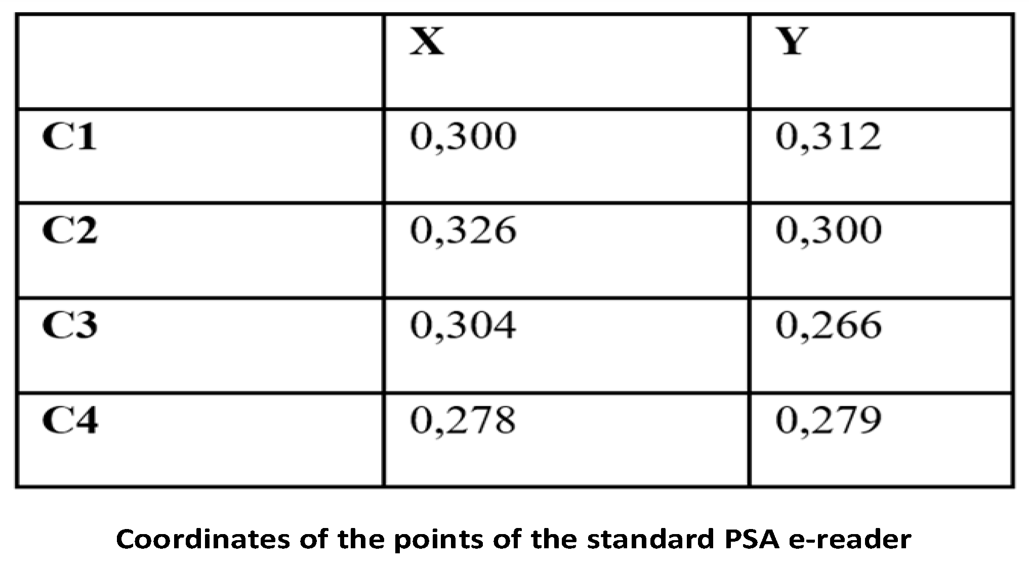
Figure A2.
Coordinates of the points of the PSA e-reader.
Figure A2.
Coordinates of the points of the PSA e-reader.
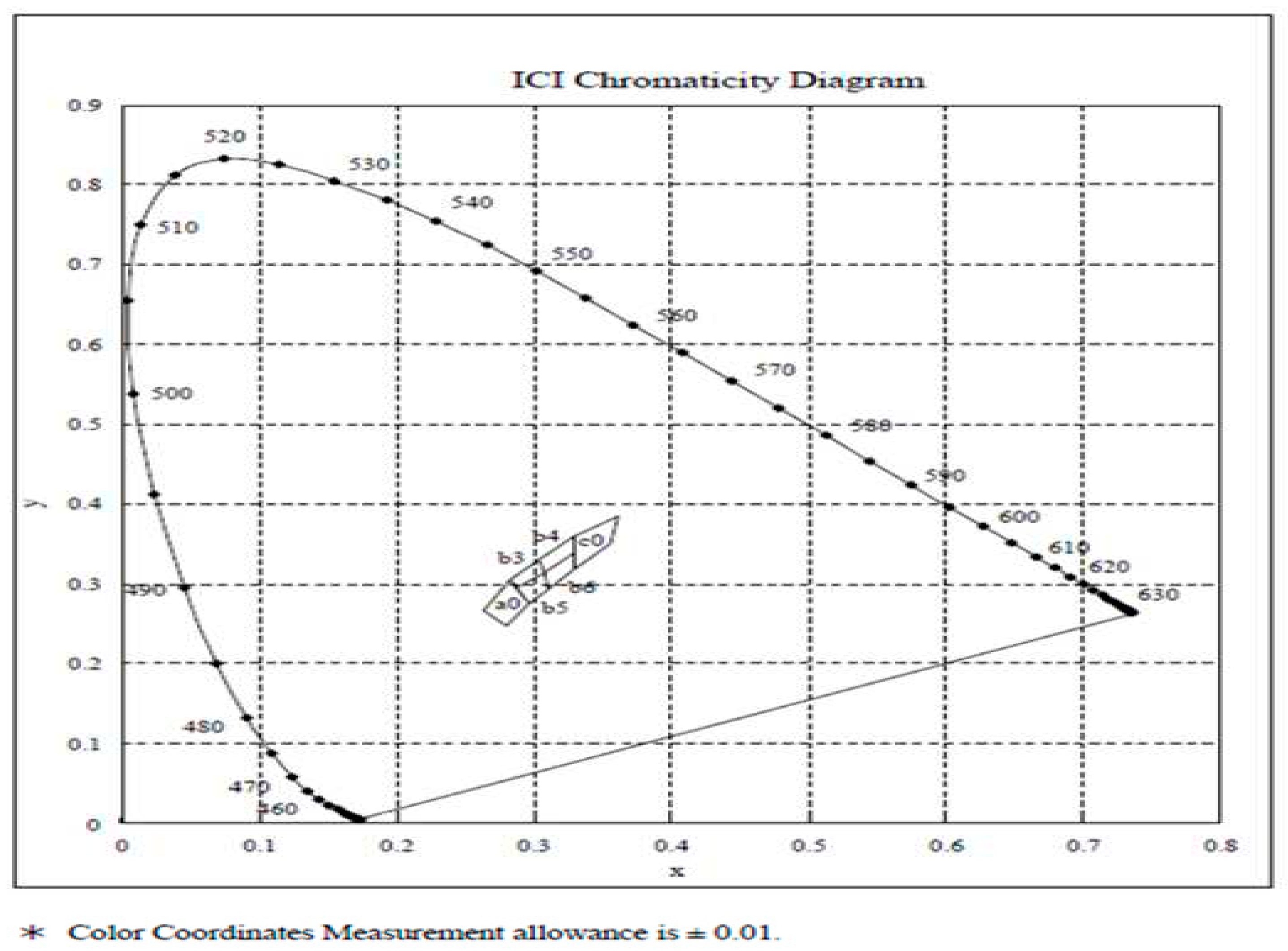
Figure A3.
ICI chromaticity diagram of the PSA e-reader.
Figure A3.
ICI chromaticity diagram of the PSA e-reader.
Appendix B: Classical Transimpedance and Transimpedance Studied
Figure A4.
Diagram of the classical transimpedance.
Figure A4.
Diagram of the classical transimpedance.
Figure A5.
Diagram of transimpedance studied.
Figure A5.
Diagram of transimpedance studied.
Appendix C: Table of Illuminance Measurements
Table A1.
Measurements using reading light with housing/case, distance of 280 mm.
Table A1.
Measurements using reading light with housing/case, distance of 280 mm.
| Lux measurement of the reading light with housing |
|---|
| Distance = 280 mm lux center = 82.8 lux |
| |
Average |
| Measurements Point 1 (lux) |
28.3 |
25.9 |
26.9 |
25 |
26.525 |
The vertical direction of the e-reader |
| Real lux Point 1 |
29.055 |
26.591 |
27.618 |
25.667 |
27.233 |
| Measurements Point 2 (lux) |
25.1 |
26.8 |
25.9 |
25.3 |
25.775 |
| Real lux Point 2 |
25.770 |
27.515 |
26.591 |
25.975 |
26.463 |
| Measurements Point 3 (lux) |
32.9 |
32.1 |
32.4 |
31.7 |
32.275 |
The horizontal direction of the e-reader |
| Real lux Point 3 |
33.778 |
32.957 |
33.265 |
32.546 |
33.137 |
| Measurements Point 4 (lux) |
31.9 |
34.3 |
31.1 |
32.7 |
32.500 |
| Real lux Point 4 |
32.752 |
35.216 |
31.930 |
33.573 |
33.368 |
| Average |
|
29.659 |
Table A2.
Measurements using reading light with housing/case, distance of 50 mm.
Table A2.
Measurements using reading light with housing/case, distance of 50 mm.
| Distance = 50 mm lux center = 82.8 lux |
|---|
| Measurements Point 1 (lux) |
1 |
1.1 |
1 |
1 |
1.025 |
The vertical direction of the e-reader |
| Real lux Point 1 |
1.083 |
1.192 |
1.083 |
1.083 |
1.111 |
| Measurements Point 2 (lux) |
1.2 |
1.1 |
1.3 |
1.2 |
1.200 |
| Real lux Point 2 |
1.300 |
1.192 |
1.408 |
1.300 |
1.300 |
| Measurements Point 3 (lux) |
9.3 |
10 |
10.2 |
8.7 |
9.550 |
The horizontal direction of the e-reader |
| Real lux Point 3 |
10.076 |
10.834 |
11.051 |
9.426 |
10.347 |
| Measurements Point 4 (lux) |
2.3 |
3.7 |
3.3 |
4 |
3.325 |
| Real lux Point 4 |
2.492 |
4.009 |
3.575 |
4.334 |
3.602 |
| Average |
|
3.932 |
Appendix D: BER Measurement Table
Table A3.
BER measurement, data transmission of various sizes.
Table A3.
BER measurement, data transmission of various sizes.
Data size
(Mbit) |
Distance (cm) |
Luminous illuminance (lux) |
Emission angle |
Receiving angle |
Transmission time |
BER (%) |
| 1.2 |
30 cm |
220 |
25° |
15° |
2 min |
0 |
| 12 |
15 min |
0 |
| 25.2 |
30 min |
0 |
| 12 |
10 min |
0 |
| 24 |
20 min |
0 |
| 12 |
2 hr 30 min |
0 |
Table A4.
BER measurement, reading light of various illuminance and various distances.
Table A4.
BER measurement, reading light of various illuminance and various distances.
| Distance (cm) |
Lighting of the reading light in the center (lux) |
Data size (Mbit) |
Emission angle |
Receiving angle |
Transmission time |
BER (%) |
| 30 |
220 |
1.2 |
25° |
15° |
2 min |
0 |
| 12 |
15 min |
0 |
| 40 |
120 |
1.2 |
25° |
15° |
2 min |
0 |
| 12 |
15 min |
0 |
| 50 |
80 |
1.2 |
25° |
15° |
2 min |
0 |
| 12 |
15 min |
0 |
| 60 |
64 |
1.2 |
25° |
15° |
2 min |
0 |
| 12 |
15 min |
0 |
| 70 |
43 |
1.2 |
25° |
15° |
2 min |
0 |
| 12 |
15 min |
0 |
Table A5.
BER measurement, data transmission of fixed sizes, reading light of various illuminance and fixed distances.
Table A5.
BER measurement, data transmission of fixed sizes, reading light of various illuminance and fixed distances.
| Distance (cm) |
Illumination (lux) |
Data size (Mbit) |
BER (%) |
| 60 |
60 |
1.2 |
0 |
| 12 |
0 |
| 50 |
1.2 |
0 |
| 12 |
0 |
| 40 |
1.2 |
0 |
| 12 |
0 |
| 30 |
1.2 |
0 |
| 12 |
0 |
| 70 |
30 |
1.2 |
0 |
References
- Haas, H. and T. Cogalan, LiFi Opportunities and Challenges, in International Symposium on Wireless Communication Systems. 2019: Oulu, Finland.
- Pure LiFi, Shedding Light on LiFi. LiFi White Papers 2016; Available from: http://purelifi.com/news_media/lifi-white-papers/.
- Wang, N., et al., A Visible Light Communication (VLC) based Intelligent Transportation System for lorry fleet, in 16th International Conference on Optical Communications and Networks (ICOCN). 2017: Wuzhen, China. p. 1-3.
- Institute, T.C. Introduction to IEEE 802.15 WPAN and Bluetooth. 2023; Available from: https://blog.oureducation.in/introduction-to-ieee-802-15-wpan-and-bluetooth/.
- Guan, H., LiFi (Light Fidelity): Système de communication par lumière visible à base de l’éclairage à LED. 2015, Université de Versailles - Paris-Saclay: Velizy, France.
- Rajagopal, S., R.D. Roberts, and S.-K. Lim, IEEE 802.15.7 visible light communication: modulation schemes and dimming support. IEEE Communications Magazine, 2012. 50(3): p. 72-82. p: 50(3). [CrossRef]
- F. Wu, et al., Performance comparison of OFDM signal and CAP signal over high capacity RGB-LED-based WDM visible light communication. IEEE Photon, 2013. 5(4): p. 7901507-1-7907507-7. [CrossRef]
- IEEE, IEEE802 Part 15.7: PHY and MAC standard for short-range wireless optical communication using visible light. 2010.
- Budinger, J.M., et al. Combinatorial pulse position modulation for power-efficient free-space laser communications. in SPIE. 1993. Los Angeles, CA.
- ATMEL, Manchester Coding Basics. 2009.
- Hammouda, M., et al. Hybrid RF/LC Systems under QoS Constraints. in 25th International Conference on Telecommunications. 2018. Saint-Malo, France.
- Singh, S., G. Kakamanshadi, and S. Gupta. Visible Light Communication - an emerging wireless communication technology. in 2nd International conference on recent advances in engineering & computational sciences 2016. Chandigarh, India.
- Ayyash, M., et al., Coexistence of WiFi and LiFi toward 5G: Concepts, opportunities, and challenges, in IEEE Communications Magazine. 2016. p. 64–71.
- Soudgar, A.I., A.U. Kulkarni, and A.R. Surve. Li-Fi: An infallible standard for future indoor communication. in International Conference of Electronics, Communication and Aerospace Technology. 2017. Coimbatore, India.
- Kulkarni, S., A. Darekar, and P. Joshi. A survey on Li-Fi technology. in International Conference on Wireless Communications, Signal Processing and Networking. 2016. Chennai, India.
- Kuppusamy, P., S. Muthuraj, and S. Gopinath. Survey and challenges of Li-Fi with comparison of Wi-Fi. in International Conference on Wireless Communications, Signal Processing and Networking. 2016. Chennai, India.
- Murawwat, S., et al. An Overview of LiFi: 5G Candidate Technology. in International Symposium on Recent Advances in Electrical Engineering. 2018. Islamabad, Pakistan.
- Ramadhani, E. and G.P. Mahardika. The Technology of LiFi: A Brief Introduction. in International Conference on Information Technology and Digital Applications. 2017. Yogyakarta, Indonesia.
- Leba, M., S. Riurean, and A. Lonica, LiFi—The path to a new way of communication, in 12th Iberian Conference on Information Systems and Technologies. 2017: Lisbon, Portugal.
- Adwani, A. and S. Nagtode. LIFi Information transferring through LED’s. in International Conference on Electrical, Electronics, and Optimization Techniques. 2016. Chennai, India.
- Albraheem, L.I., et al., Toward Designing a Li-Fi-Based Hierarchical IoT Architecture. IEEE Access, 2018. 6: p. 40811–40825. [CrossRef]
- Ali, K., et al. IoRL Indoor Location Based Data Access, Indoor Location Monitoring & Guiding and Interaction Applications. in IEEE International Symposium on Broadband Multimedia Systems and Broadcasting. Valencia, Spain.
- Johri, R. LiFi, complementary to WiFi. in International Conference on Computation of Power, Energy Information and Commuincation. 2016. Melmaruvathur, India.
- Kumar, N.V.R., et al. Comparison of LIFI and WIFI and study of smart meter-survey. in International Conference on Information Communication and Embedded Systems. 2017. Chennai, India.
- Isabella Mariya, A., et al. Li-Fi Based Blind Indoor Navigation System. in 5th International Conference on Advanced Computing & Communication Systems. Coimbatore, India.
- Jha, V., Study of machine learning methods in intelligent transportation systems, in Electrical Engineering. 2015, University of Nevada: Las Vegas, Nevada, USA.
- Fernandez, S., et al., Ontology-Based Architecture for Intelligent Transportation Systems Using a Traffic Sensor Network. Sensors, 2016. 16(8). [CrossRef]
- Jamuna, R., et al., LIFI for Smart Transportation: Enabling Secure and Safe Vehicular Communication. Journal of Xi’an Shiyou University, Natural Science Edition, 2023. 19(5): p. 1-8.
- Santhosam, B., D. Divya, and R. Priyanka, VANET based Intelligent TransportationSystem using LiFi technology. IOSR Journal of Electronics and Communication Engineering. 12(2): p. 30-32.
- Saravanan, M., J. Ajayan, and P.Mamikandan. Li-Fi Technology for Vehicle-to-Vehicle Communication. in International Conference on Edge Computing and Applications. 2022. Tamilnadu, India.
- Hina, M.D., et al., CASA: An Alternative Smartphone-Based ADAS. International Journal of Information Technology & Decision Making. 21(1): p. 273-313. [CrossRef]
- Seymour, T. ADAS technology contributes to 32% rise in vehicle repair costs. 2017; Available from: https://www.fleetnews.co.uk/news/manufacturer-news/2017/06/28/adas-technology-contributes-to-32-rise-in-vehicle-repair-costs.
- Pullia, A., et al., A low-noise large dynamic-range readout suitable for laser spectroscopy with photodiodes. 2012, Department of Physics, University of Milano: Milan, Italy.
- Cailean, A., Etude et réalisation d’un système de communications par lumière visible (VLC/LiFi), Application au domaine automobile, in Optics/Photonic. 2014, Université de Versailles Saint-Quentin en Yvelines: Velizy, France.
| 1 |
PSA Peugeot-Citroën is a French vehicle company, maker of Peugeot and Citroën vehicles. |
| 2 |
LISV (Laboratoire d’ingénierie des systèmes de Versailles) is a research laboratory of the University of Versailles – Paris-Saclay in Vélizy, France. |
| 3 |
|
Figure 1.
The electromagnetic spectrum.
Figure 1.
The electromagnetic spectrum.
Figure 2.
Functionality of different network layers.
Figure 2.
Functionality of different network layers.
Figure 3.
PPM and Manchester Coding.
Figure 3.
PPM and Manchester Coding.
Figure 4.
Design of LiFi Intra-vehicular data transmission system.
Figure 4.
Design of LiFi Intra-vehicular data transmission system.
Figure 5.
Principle of operation of LiFi.
Figure 5.
Principle of operation of LiFi.
Figure 6.
Schema of data flow in the intra-vehicular data transmission system.
Figure 6.
Schema of data flow in the intra-vehicular data transmission system.
Figure 7.
Visualization of the application’s interface and its program implementation.
Figure 7.
Visualization of the application’s interface and its program implementation.
Figure 8.
Composition of a Raspberry Pi.
Figure 8.
Composition of a Raspberry Pi.
Figure 9.
FileZilla interface.
Figure 9.
FileZilla interface.
Figure 10.
Connecting nomad devices to Ethernet (a) IpadPro, (b) Microsoft Surface 3.
Figure 10.
Connecting nomad devices to Ethernet (a) IpadPro, (b) Microsoft Surface 3.
Figure 11.
The PSA e-reader: (a) – physical sample without housing or case, (b)its electric diagram.
Figure 11.
The PSA e-reader: (a) – physical sample without housing or case, (b)its electric diagram.
Figure 12.
Current-voltage characteristic of the Nichia LED.
Figure 12.
Current-voltage characteristic of the Nichia LED.
Figure 13.
Electrical diagram of the e-reader.
Figure 13.
Electrical diagram of the e-reader.
Figure 14.
Comparison of spectrum diagrams of a photodiode and an e-reader.
Figure 14.
Comparison of spectrum diagrams of a photodiode and an e-reader.
Figure 15.
Comparison of the measured current-voltage relationship and that in the datasheet.
Figure 15.
Comparison of the measured current-voltage relationship and that in the datasheet.
Figure 16.
Measured current-voltage relations of the original and modified e-readers.
Figure 16.
Measured current-voltage relations of the original and modified e-readers.
Figure 17.
Electrical power of the original e-reader and modified e-readers.
Figure 17.
Electrical power of the original e-reader and modified e-readers.
Figure 18.
Spectrum diagram measured on the original e-reader with and without the case.
Figure 18.
Spectrum diagram measured on the original e-reader with and without the case.
Figure 19.
Reading light illuminance test plan.
Figure 19.
Reading light illuminance test plan.
Figure 20.
Illumination zone measured for 65 lux and 55 lux.
Figure 20.
Illumination zone measured for 65 lux and 55 lux.
Figure 21.
Assembly diagram.
Figure 21.
Assembly diagram.
Figure 23.
Flow measurement with ambient light.
Figure 23.
Flow measurement with ambient light.
Figure 25.
Architecture of the BER test bench.
Figure 25.
Architecture of the BER test bench.
Figure 26.
Data transmission between two FTDI’s.
Figure 26.
Data transmission between two FTDI’s.
Figure 27.
Architecture of the test bench program.
Figure 27.
Architecture of the test bench program.
Figure 28.
Program compilation chain.
Figure 28.
Program compilation chain.
Figure 29.
Program compilation chain BER test for wired link.
Figure 29.
Program compilation chain BER test for wired link.
Table 1.
Comparison between LiFi and WiFi.
Table 1.
Comparison between LiFi and WiFi.
| |
LiFi |
WiFi |
| Meaning |
Light Fidelity |
Wireless Fidelity |
| Invented by |
Invented by Prof. Harald Haas in 2011 |
Invented by NCR Corp. in 1991 |
| Standard |
Uses IEEE 802.15.7 standard |
Uses IEEE 802.11 standard |
| Working Environment |
Highly dense environment where VSL (visible light spectrum) is less susceptible to external interference |
Less dense environment due to interference-related issues |
| Transmission Speed |
Very Fast, compared to WiFi |
Very slow, compared to LiFi |
| Security |
More secure data transfer since light cannot pass through walls |
Radio frequency signals pass through walls. Secured data transfer is a challenge |
| Operation |
Uses visible light spectrum for data transmission |
Uses radio waves for data transmission |
| Coverage |
Based on the medium of propagation; area of around 10 meters |
An area of up to 32 meters away |
| Frequency Bands |
Between 380 nm and 780 nm in the wavelength range |
Operates on two frequency bands, 2.4 GHz, and 5 GHz |
| Bandwidth |
Unlimited bandwidth is available |
Limited bandwidth is available |
| Components |
Uses light signals and LED bulbs for wireless data transmission |
Uses modems and radio frequency signals |
| Cost |
Installation cost is a bit high but lower than WiFi overall |
Comparatively higher than LiFi |
| Effect on Health |
No side effect |
Radio wave side effect |
| Application |
Used in healthcare, underwater communication, high-speed internet via streetlights, smart power plants, and Airlines |
Used to browse the Internet via WiFi hotspot |
Table 2.
Measurements from original reading light (with and without housing/case).
Table 2.
Measurements from original reading light (with and without housing/case).
| Distance from source (mm) |
Zone diameter (mm) |
Resistance |
Average illuminance measured with housing (lux) |
Average illuminance measured without housing (lux) |
| 600 |
280 |
R = 220 Ω |
29,659 |
18,686 |
| R = 130 Ω |
35,638 |
32,171 |
| 500 |
R = 220 Ω |
3,932 |
14,345 |
| R = 130 Ω |
3,378 |
22,657 |
| 200 |
200 |
R = 220 Ω |
39,504 |
132,231 |
| R = 130 Ω |
6,225 |
177,343 |
Table 3.
Measurements obtained from the prototype under closed curtain condition.
Table 3.
Measurements obtained from the prototype under closed curtain condition.
| V=12V, R= 220(, Closed white curtain, nuanced sky, Room R214 LISV, July 21, 2023 |
|---|
| Light meter Test 545 (OLEDCOMM) |
| Distance (mm) |
300 |
600 |
900 |
| Reading light on (lux) |
466 |
230 |
186 |
| Illuminance ambient light (lux) |
316 |
182 |
157 |
| Reading light (lux) |
150 |
48 |
29 |
| Bit Rate (kb/s) |
200-300 |
200-300 |
0-200 |
| Video effect |
Format 1280 * 720, a little blocked |
Format 1280 * 720, a little blocked |
Format 1280 * 720, quite blocked |
| Format 480 * 360, no blocking |
Format 480 * 360, no blocking |
Format 480 * 360, a little blocked |
| Music effect |
No blocking |
No blocking |
A little blocked |
Table 4.
Measurements obtained from the prototype under a dark condition.
Table 4.
Measurements obtained from the prototype under a dark condition.
| V=12V, In the dark with lamp light, LISV Storage Room, July 21, 2023 |
|---|
| Light meter Testo 545 (OLEDCOMM) |
| Distance (mm) |
300 |
600 |
900 |
| original reading light (lux) |
140 |
46 |
27 |
| Bit Rate (kb/s) |
200-300 |
200-300 |
0-200 |
| Modified reading light (lux) |
170 |
65 |
40 |
| Bit Rate (kb/s) |
150-320 |
150-300 |
0-200 |
| Video effect |
Format 1280 * 720, a little blocked |
Format 1280 * 720, a little blocked |
Format 1280 * 720, quite blocked |
| Format 480 * 360, no blocking |
Format 480 * 360, no blocking |
Format 480 * 360, a little blocked |
| Music effect |
No blocking |
No blocking |
A little blocked |
|
Disclaimer/Publisher’s Note: The statements, opinions and data contained in all publications are solely those of the individual author(s) and contributor(s) and not of MDPI and/or the editor(s). MDPI and/or the editor(s) disclaim responsibility for any injury to people or property resulting from any ideas, methods, instructions or products referred to in the content. |
© 2023 by the authors. Licensee MDPI, Basel, Switzerland. This article is an open access article distributed under the terms and conditions of the Creative Commons Attribution (CC BY) license (http://creativecommons.org/licenses/by/4.0/).
