Development
Skipping the introduction, materials and methods, and results, we go directly to the discussion of these obtained results. The design consists of an inductive-capacitive type circuit.
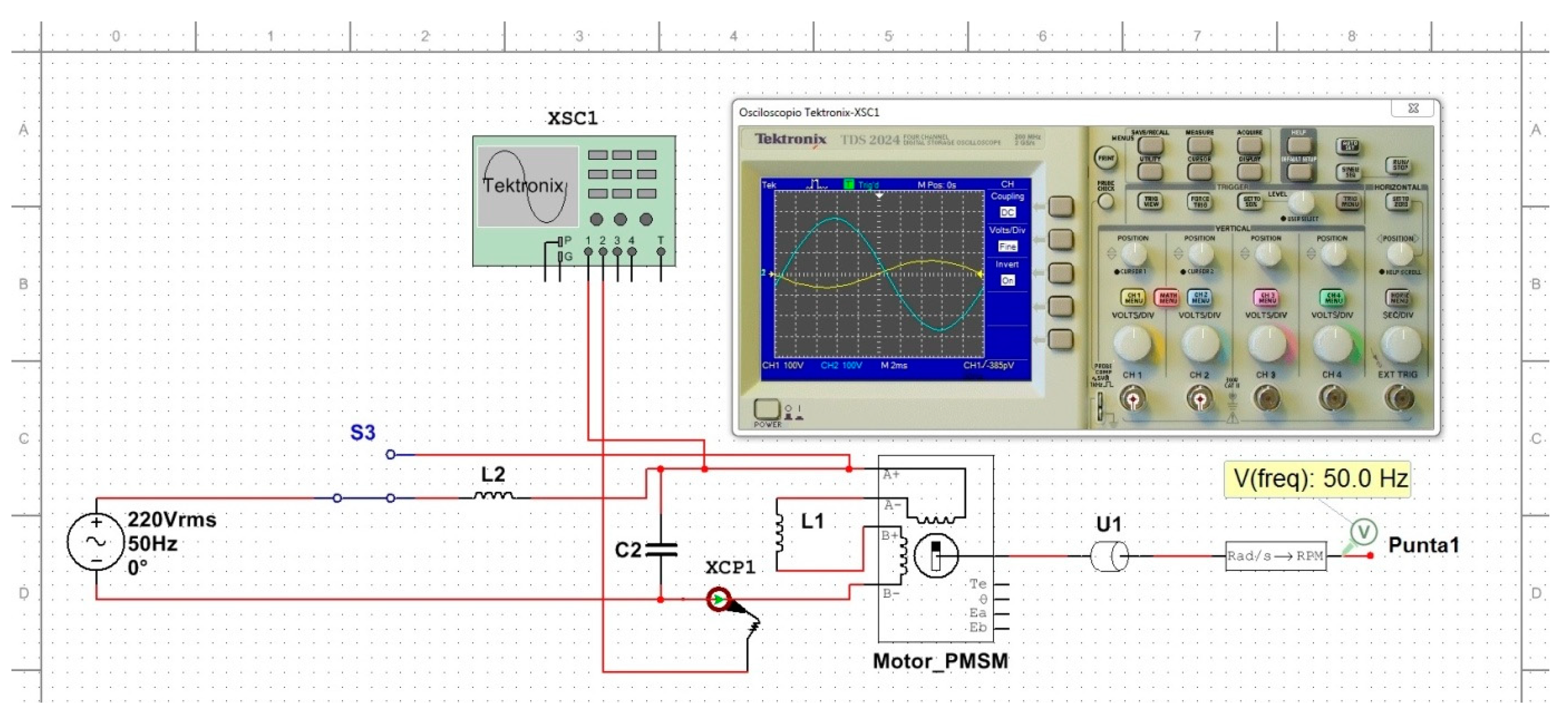
The oscilloscope displays the phase shift between the total voltage and total current of the LC circuit. It is an inductive circuit with a phase shift of 79.82 degrees (with the energy efficiency circuit “off”), where the voltage leads the current. When the energy efficiency circuit is “on,” the phase shift between voltage and current is 90 degrees, and the voltage (Volts) continues to lead the current (Amperes). It is clearly observed how the voltage of 220 (V) and current of 0.45 (A) decrease to 110 (V) and 0.10 (A). What’s important is what happens in both cases - the SPDT switch “off” or “on” - at the probe (Point 1), which records the detail of the analyzer tip, converting radians per second (Rad/s) to revolutions per minute (RPM), and then to frequency (Hertz) of the mechanical work performed by the rotor on the centrifugal radial blades (load). It is observed that it always rotates at 3000 (RPM), which is equivalent to 50 (Hz), a result of the synchronous motor’s frequency. Regardless of whether the SPDT switch is “off” or “on” in energy efficiency (EE) mode, in both cases, the alternating current frequency is always 50 (Hz). For this reason, the motor, even if its torque decreases, does not decrease its speed.
Figure 1.
Design of the LC circuit simulated by computer software NI Multisim 14.0. The circuit is turned on and off through the SPDT switch (S3), powered by a single-phase alternating current (AC) voltage source of 220 (VAC) and 50 (Hz). It consists of a capacitive reactance (C2) and an inductive reactance (L2), which are responsible for processing the binomial expression of impedance. The capacitive reactance is obtained from a 3 (μF) capacitor connected in parallel to the two phases, and its function is power factor correction (cosine of phi). The 1.5 (Henry) inductance is connected in series to one of the phases of the AC voltage source, and its function is to limit the flow of current or amperage to reduce single-phase active energy consumption. Although the permanent magnet synchronous motor (PMSM) is simulated with a bipolar stepper motor (which would require a half-step controller for two phases), it still behaves similarly to a PMSM when powered by single-phase AC electrical current. It has an internal resistance (L1) since it is a coil, so the entire system behaves like an RCL circuit (simultaneously filtering current and voltage harmonics). The system is connected to a load (U1) representing the impeller blades, and there is a converter from (Rad/s) to (RPM) at Tip (1) displaying the speed (or frequency) in Hertz. Source: Own elaboration.

Figure 2.
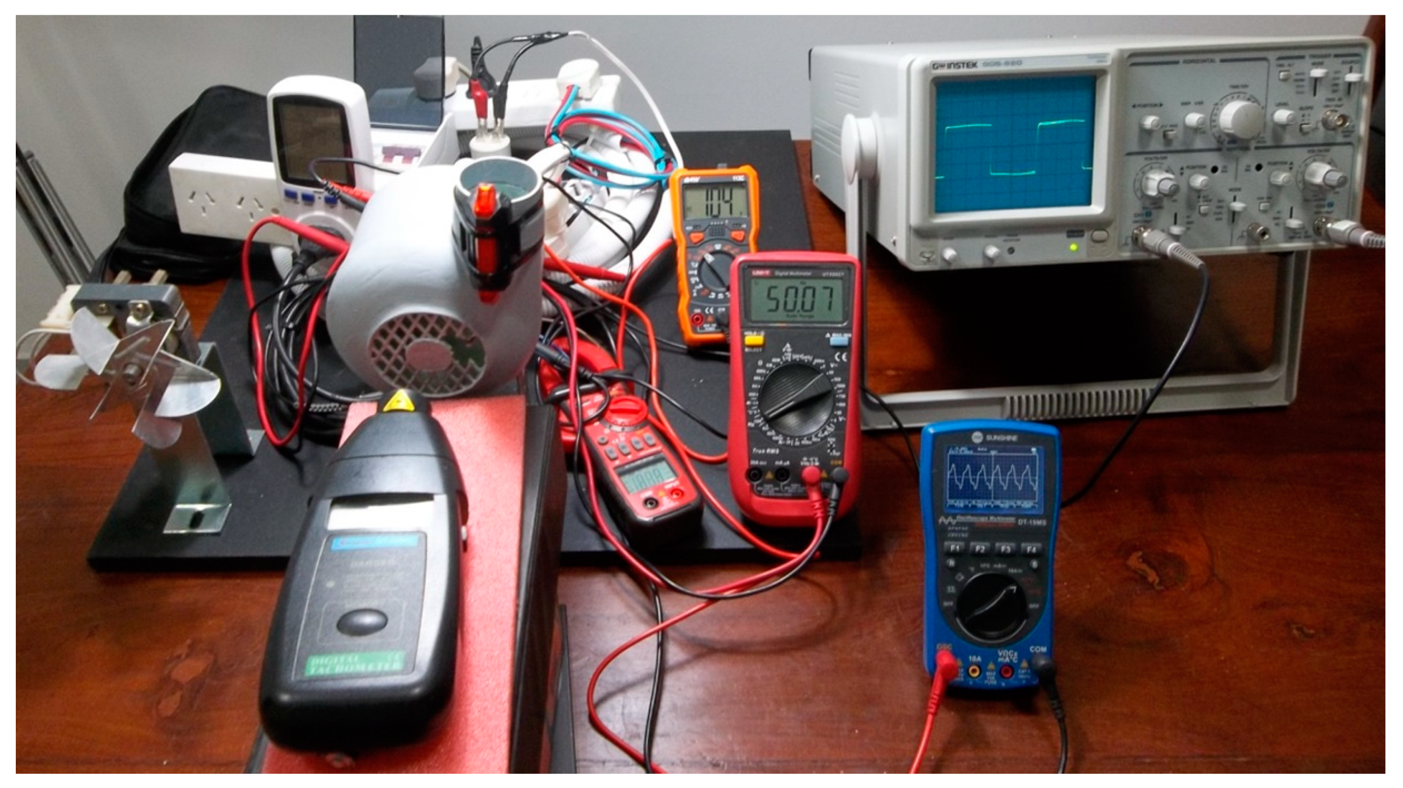
Test bench connected to the PMSM type synchronous motor (as an example). With digital multimeter (volt meter in AC), amperometric clamp (current intensity meter in AC), frequency meter (Hertz meter), laser photocometer (speed meter in RPM), digital oscilloscope waveform meter the alternating current in voltage (Vpeak -peak, Vavg, Vrms), for calculation of the crest factor of harmonic distortion, analog oscilloscope for qualitative observation of the THD (harmonic distortion of alternating current), wattmeter (active power meter in watts or watts), power factor (cosine of fi), power -meter (meter of active energy consumption in kilowatt-hours: kWh). Source: self made.
Figure 3.
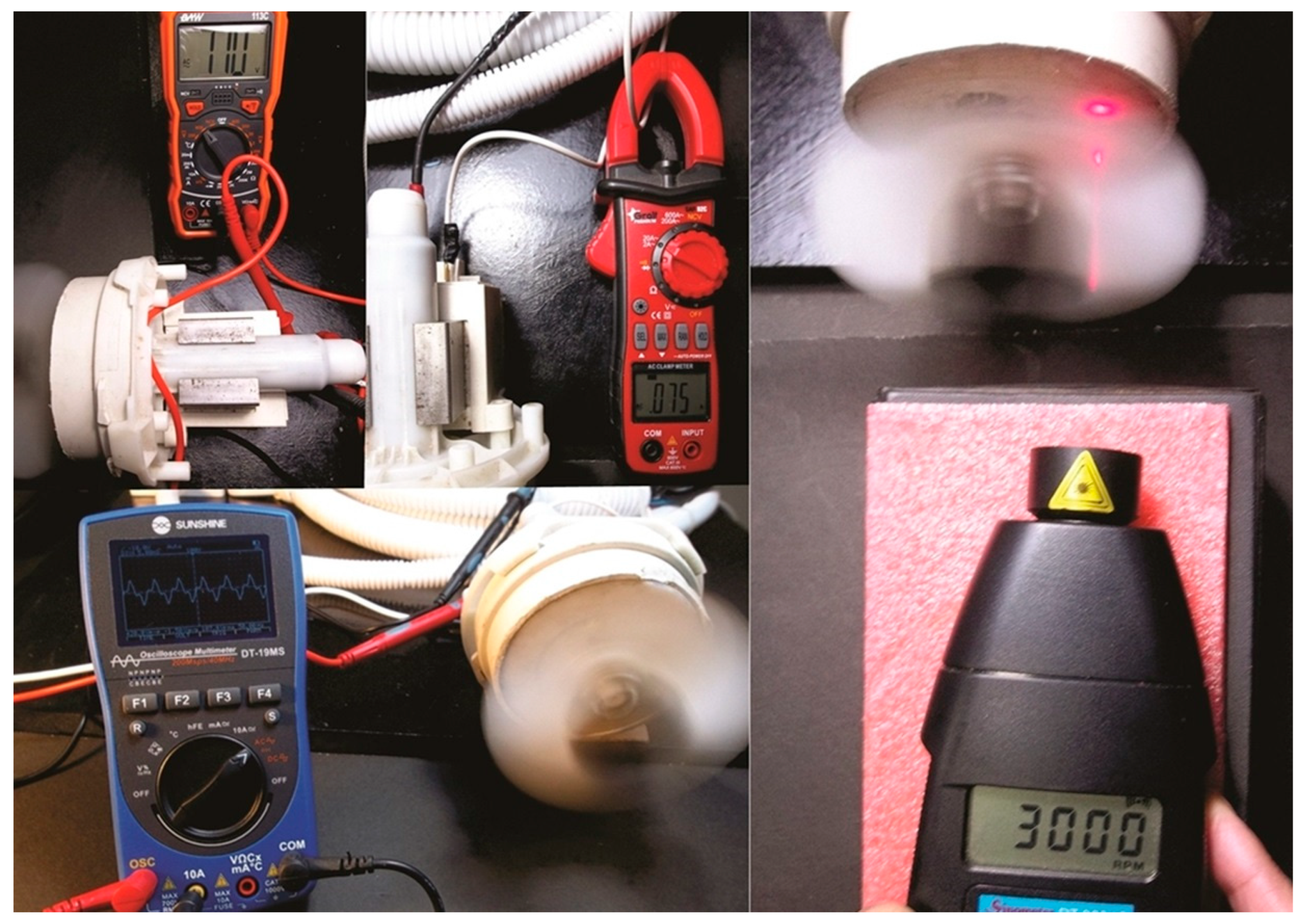
PMSM/IPM type synchronous motor (with the energy efficiency system “on”) connected to the oscilloscope showing the non-linear voltage waveform, also connected to the digital multimeter showing the voltage drop of 110 (Volts), and the amperometric clamp evidencing the drop in the circulation of the electric current at 0.075 (amperes) and the constant in the speed of the blade at 3000 (RPM). Source: self made.
Figure 5.
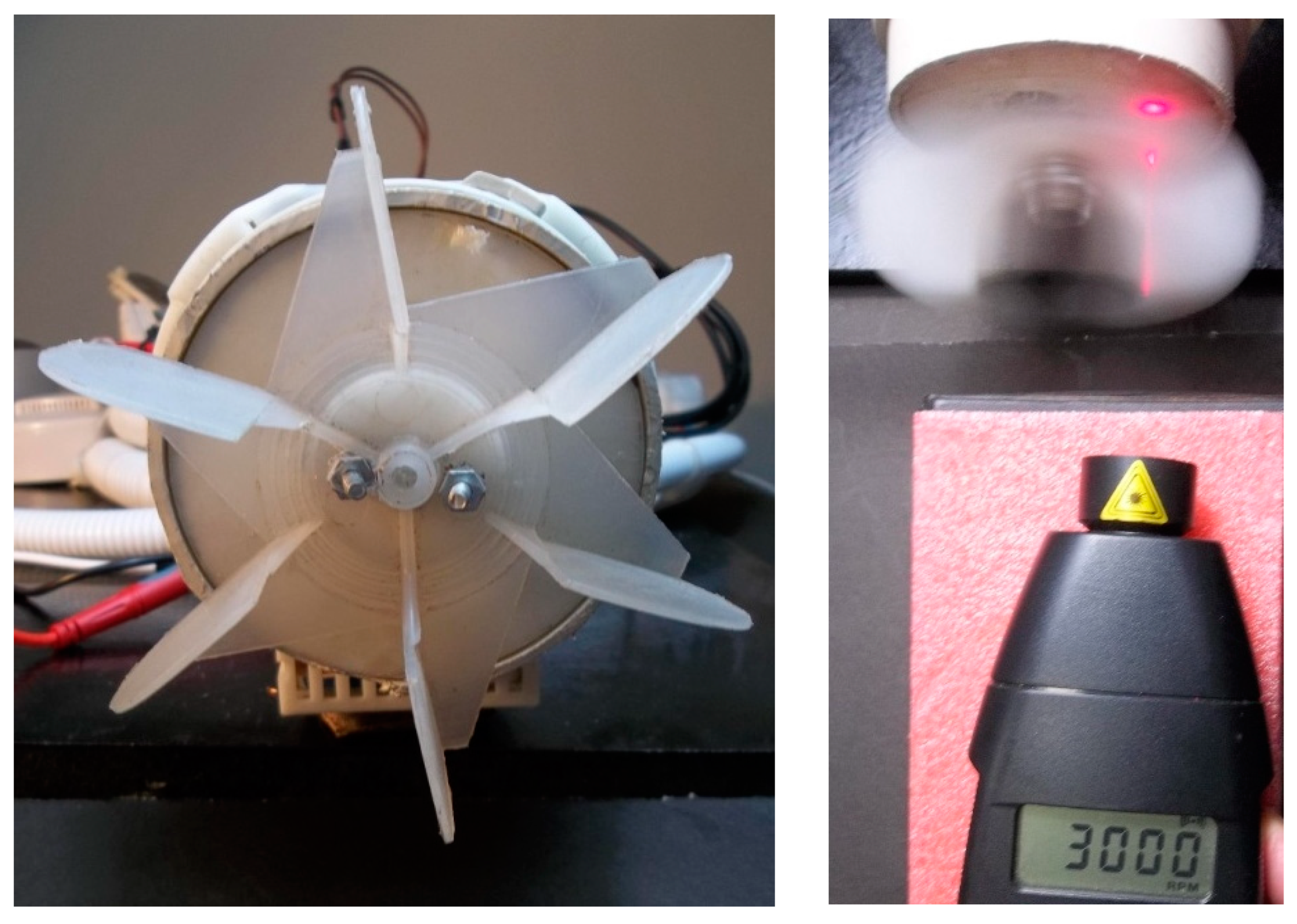
(a) PMSM type synchronous motor (obtained from the electric pump of a washing machine with a nominal power of 50 watts) stopped with the 10.5 (mm) blades used in the experiment; (b) it rotating at 3000 (RPM) at maximum power of 6.3 (Watts). Source: self made.
Figure 5.
(a) PMSM type synchronous motor (obtained from the electric pump of a washing machine with a nominal power of 50 watts) stopped with the 10.5 (mm) blades used in the experiment; (b) it rotating at 3000 (RPM) at maximum power of 6.3 (Watts). Source: self made.
According to the “Fan Affinity Law” specified in Standard UNE 100-230-95, the power absorbed by a fan with an asynchronous motor varies with the cube of its speed. Testing one of the so-called “fan affinity laws,” with the impeller diameter (blades) constant, the electrical power absorbed by the blower motor is proportional to the cube of the shaft speed, according to the following equation:
“Where “P” is power (in Watts) and “N” is speed (in RPMs).
This means that for a small change in rotational speed, the power changes significantly. This has significant implications from an energy efficiency (EE) perspective.
For all the comparisons presented below, it has been taken into account that the density of the air does not vary in any case (it is always the same): approximately 1.204 kg/m3 (0.0752 lb/cu ft), according to the International Standard Atmosphere (ISA), at 101.325 kPa (abs) and 15 °C (59°F).”
Siendo “P” potencia (en Watts) y “N” velocidad (en RPMs).


