Submitted:
12 October 2023
Posted:
13 October 2023
You are already at the latest version
Abstract
Keywords:
1. Introduction
2. Materials and Methods
2.1. Data Structuring
- First loop over the timesteps to identify the maximum number of concurrent IDs in a single timestep (maximum instantaneous "size" of the self-injected beam).
- Identification of the array of unique IDs , with size .
- Creation of temporary arrays with dimensions or .
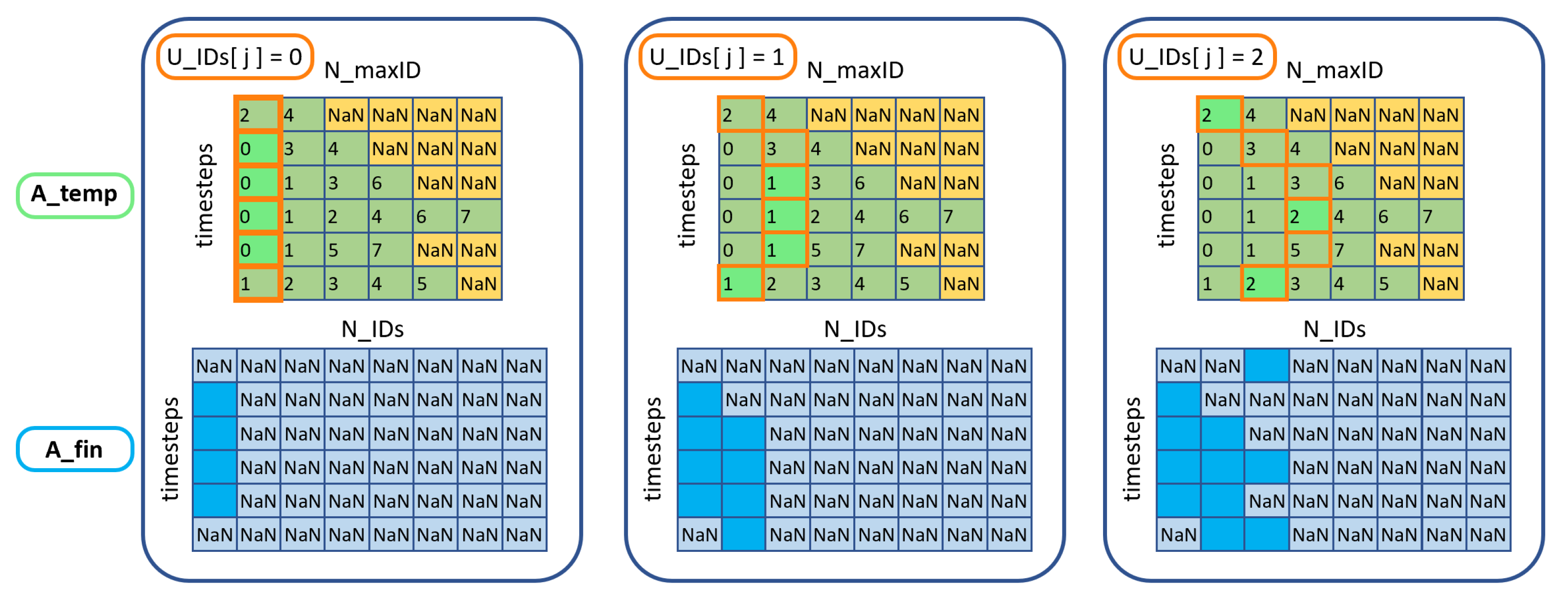
- Second loop over the timesteps, sorting the variables by ID values, and inserting them into the arrays. Note that in a timestep (row of ), the number of present IDs may generally be . In these cases, the variables sorted by ID will be accumulated in the leftmost columns of , while NaNs will be left in the free cells. (see leftmost block in Figure 1, green/yellow array matrix)
- Creation of final arrays filled with NaN values, with dimensions or (see leftmost block in Figure 1, blue array matrix).
- ID alignment: a single loop with index (j) over . A counter array with size is incremented only at positions i where . The same indices for which this condition is satisfied are used to extract the variables from and insert them into . A visual representation of the loop is presented in Figure 1, going from left box to the right one.
2.2. Spectrum calculation
- 1.
-
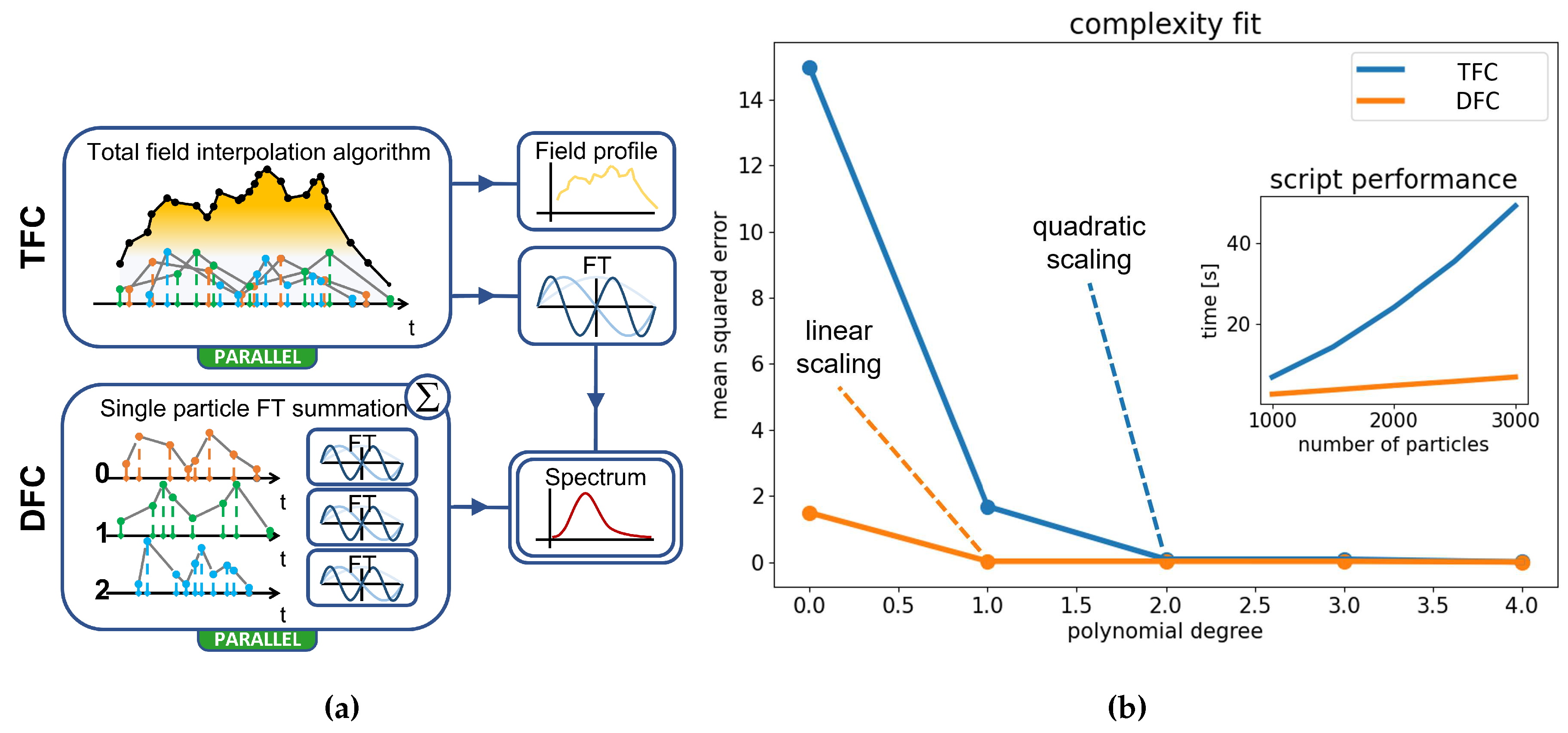
Total Field Calculation (TFC): To proceed in this manner, it is necessary to interpolate the fields produced by each particle on the detector. This is done using a specifically designed algorithm where:
- all the fields on the detector are combined into a single array, which is then sorted based on
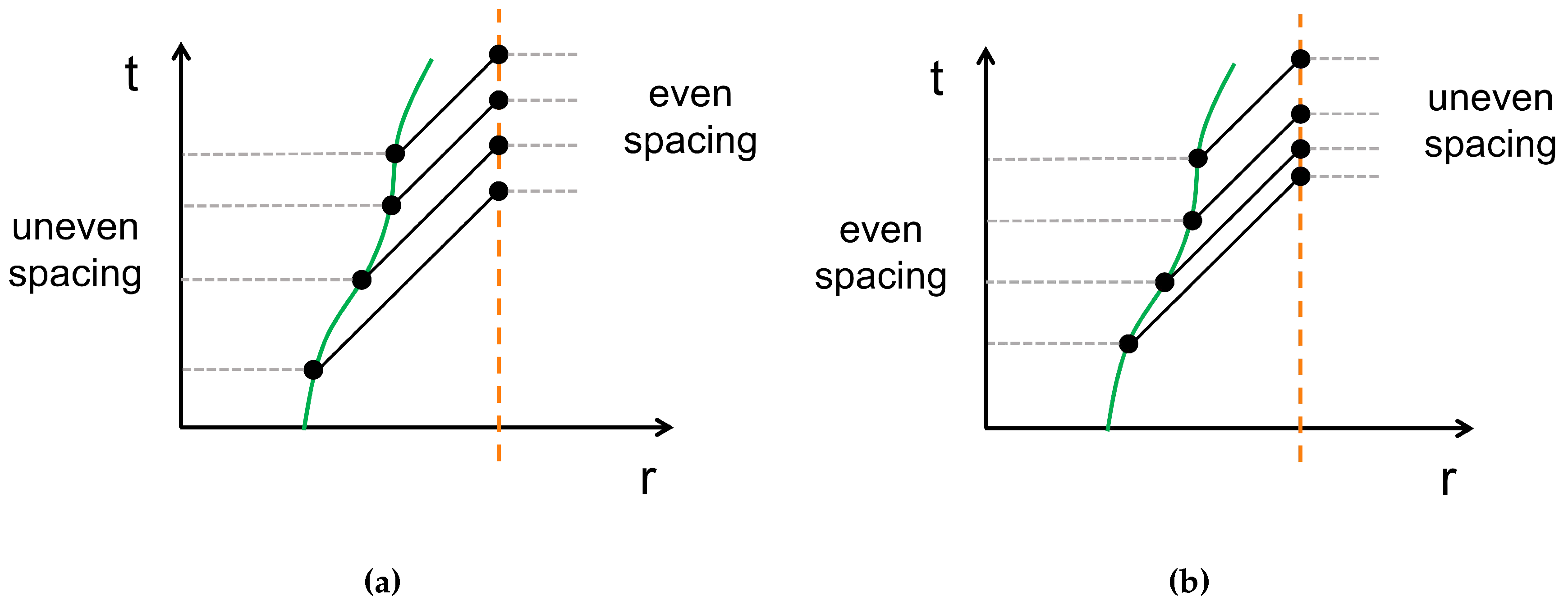
- concurrently, a container of size is filled by interpolating the field of each particle i at all the missing time points
- finally, the ordered fields from the first step are directly summed into the container, providing the temporal profile of the total field
Then to compute the spectrum it is possible to perform a Fourier Transform (FT) directly on the total field on the detector, using as the array of times. - 2.
- Direct FT Calculation (DFC): In this faster approach, we exploit the principle of superposition of fields to decompose a single FT of the total field into a sum of FTs on the fields of individual particles. The obtained spectrum is identical to the TFC case, but the information about the temporal profile of the field is lost.
3. Results
3.1. Validation
3.2. Betatron radiation analysis: a peculiar case
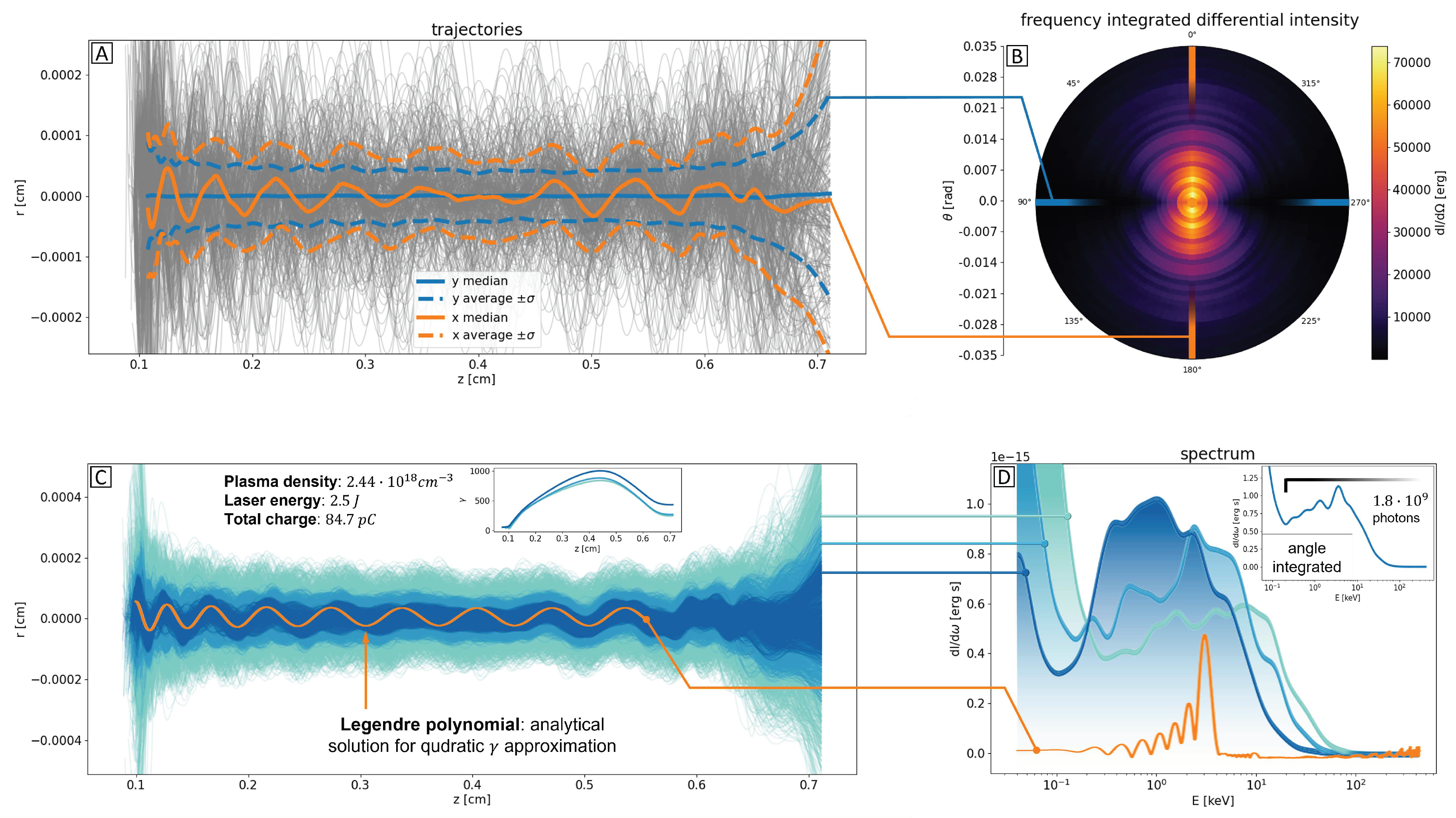
- Decrease in the cutoff energy.
- Decrease in the extension of the low-energy background (left).
- Increase in peak intensity.
4. Conclusions
Funding
Data Availability Statement
References
- Assmann, R. W.; Ferrario, M. et al. EuPRAXIA Advanced Photon Sources PNRR_EuAPS Project, 2023.
- Assmann, R. W.; Ferrario, M. et al. EuPRAXIA Conceptual Design Report; Springer Science and Business Media LLC, 2020. [CrossRef]
- Esarey, E.; Shadwick, B. A.; Catravas, P.; Leemans, W. P. Synchrotron radiation from electron beams in plasma-focusing channels; APS, 2002. [CrossRef]
- Kostyukov, I.; Kiselev, S.; Pukhov, A. X-ray generation in an ion channel; AIP, 2003. [CrossRef]
- Paroli, B.; Potenza, M. A. C. Radiation emission processes and properties: synchrotron, undulator and betatron radiation; Editor: Informa UK Limited, 2017. [CrossRef]
- FBPIC (Fourier-Bessel Particle-In-Cell) documentation: https://fbpic.github.io/.
- Lehe, R.; Kirchen, M.; Andriyash, I. A.; Godfrey, B. B.; Vay, J. A spectral, quasi-cylindrical and dispersion-free Particle-In-Cell algorithm; Computer Physics Communications, 2016. [CrossRef]
- Jackson, J. D. Radiation from Moving Charges. In Classical electrodynamics, 2nd ed.; Editor: Wiley, 1975.
- Smilei documentation: https://smileipic.github.io/Smilei/.
- Ciocci, F. ; Dattoli, G.; Renieri, A.; Torre, A. Generalities on Synchrotron Radiation. In Insertion Devices For Synchrotron Radiation And Free Electron Laser; Editor: World Scientific Publishing Company, 2000.
Disclaimer/Publisher’s Note: The statements, opinions and data contained in all publications are solely those of the individual author(s) and contributor(s) and not of MDPI and/or the editor(s). MDPI and/or the editor(s) disclaim responsibility for any injury to people or property resulting from any ideas, methods, instructions or products referred to in the content. |
© 2023 by the authors. Licensee MDPI, Basel, Switzerland. This article is an open access article distributed under the terms and conditions of the Creative Commons Attribution (CC BY) license (http://creativecommons.org/licenses/by/4.0/).


