1. Introduction
The robotics research community has a strong focus on autonomous navigation in dynamic environments, particularly for the development of intelligent autonomousguided robots with significant industrial applications. The use of mobile robots in manufacturing, warehousing, and construction is on the rise. Real-world scenarios pose challenges when robots and humans share the same environment, necessitating effective human-robot interaction mechanisms. For example, in manufacturing, autonomous guided vehicles may encounter human obstructions and need to implement collision avoidance measures. Researchers in this field have explored a range of methodologies incorporating various sensor types, including laser measurement systems [
1], Lidar sensors [
2,
3], cameras [
4], among others.
Artificial intelligence (AI) techniques show significant potential in tackling complex challenges within dynamic and uncertain environments. Robots able to demonstrate complex behaviors by interpreting their environment and adapting their actions through sensors and ANFIS control mechanisms are commonly referred as behavior-based systems. The application of fuzzy logic and neural networks has demonstrated effectiveness in the domain of autonomous robot navigation [
5,
10].
Al-Mayyahi et al. [
5] present a novel approach that utilizes an Adaptive Neuro-Fuzzy Inference System (ANFIS) to address navigation challenges encountered by an Autonomous Guided Vehicle (AGV). The system is comprised of four ANFIS controllers; two regulate the AGV's angular velocities for reaching the target, while the remaining two focus on making optimal heading adjustments to avoid obstacles. For low-level motion control, the velocity controllers receive input from three sensors, including front distance, right distance and left distance. Meanwhile, the heading controllers consider the angle difference between the AGV's current heading and the angle needed to reach the target in order to determine the best direction.
Miao et al. [
6] presented a novel obstacle avoidance fuzzy controller utilizing fuzzy control algorithms. This controller utilized operational data to establish an AGV adaptive neuro-fuzzy network system, capable of providing precise behavioral commands for AGV's dynamic obstacle avoidance.
Haider et al. [
7] introduced a solution that leverages an Adaptive Neuro-Fuzzy Inference System (ANFIS) in conjunction with a Global Positioning System (GPS) for control and navigation, effectively addressing these issues. The proposed approach automates mobile robot navigation in densely cluttered environments, integrating GPS and heading sensor data fusion for global path planning and steering. A fuzzy inference system (FIS) is employed for obstacle avoidance, incorporating distance sensor data as fuzzy linguistics. Furthermore, a type-1 Takagi–Sugeno FIS is utilized to train a five-layered neural network for local robot planning, with ANFIS parameters fine-tuned through a hybrid learning method.
Farahat et al. [
8] focuses on an extensive analysis and investigation into AI algorithm techniques for controlling the path planning of a four-wheel autonomous robot, enabling it to autonomously reach predefined objectives while intelligently circumventing static and dynamic obstacles. The research explores the viability of employing Fuzzy Logic, Neural Networks, and the Adaptive Neuro-Fuzzy Inference System (ANFIS) as control algorithms for this intricate navigation task.
This paper [
9] explores a vision guidance system for Automated Guided Vehicles (AGV) that leverages the Adaptive Network Fuzzy Inference System (ANFIS). The vision guidance system is founded on a driving method capable of recognizing salient features such as driving lines and landmarks, providing a data-rich alternative to other induction sensors in AGVs. However, the camera's sensitivity to varying light conditions necessitates the creation of a controlled dark-room environment to mitigate disturbances. Despite the reduced viewing angles resulting from the dark-room design, conventional PID control struggles with swift maneuvers on driving lines. Consequently, this paper introduces a vision guidance approach employing ANFIS. The AGV model is constructed through kinematic analysis of the camera and the dark-room setup. Steering angle adjustments are facilitated through Fuzzy Inference Systems (FIS), with the data being trained via a hybrid ANFIS training method to facilitate driving control.
Khelchandra et al. [
10] introduced a method for path planning considering mobile robot navigation within environments with static obstacles, which combines neuro-genetic-fuzzy techniques. This approach involves training an artificial neural network to select the most suitable collision-free path from a range of available paths. Additionally, a genetic algorithm is employed to enhance the efficiency of the fuzzy logic system by identifying optimal positions within the collision-free zones.
Mohammed Faisal. [
11] presented a technique for fuzzy logic-based navigation and obstacle avoidance in dynamic environments. This method integrates two distinct fuzzy logic controllers: a tracking fuzzy logic controller, which steers the robot toward its target, and an obstacle avoidance fuzzy logic controller. The principal aim of this research is to demonstrate the utility of mobile robots in material handling tasks within warehouse environments. It introduces a notable departure from the traditional colored line tracking approach, replacing it with wireless communication methods.
Within our methodology, we employ a combination of four Adaptive Neuro-Fuzzy Inference Systems (ANFIS) to facilitate mobile robot navigation towards a designated destination while ensuring collision avoidance capabilities for both stationary and mobile obstacles. The approach focuses on the application of a path planning algorithm to establish an efficient route from the starting point to the target, ensuring a smooth path within a static environment. During this initial phase, two ANFIS controllers are dedicated to tracking and guiding the robot towards its objective. However, if the robot encounters a mobile obstacle during its trajectory, we activate another pair of ANFIS controllers specifically tailored for obstacle avoidance maneuvers. Once the obstacle avoidance action is executed, the robot smoothly resumes its original planned path.
2. Autonomous Guided Vehicle Kinematics
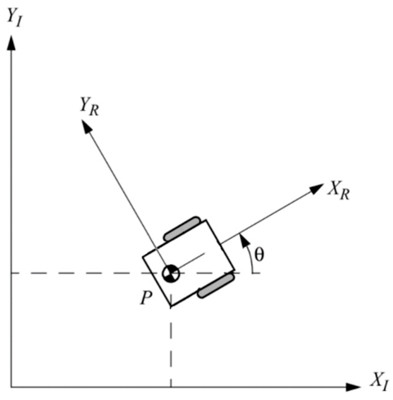
The main scopus is to devise a control system that guarantees the safe navigation of a mobile robot in a dynamic environment, while considering its kinematic and geometric characteristics. This is accomplished by defining two essential frames for depicting the mobile robot's motion as a rigid body: the global reference frame, which remains stationary relative to the world, and the local reference frame, which is fixed to the robot itself. This approach sets the foundation for robust control in dynamic environments.
Figure 1.
The kinematic model of the wheeled robot's motion is grounded on three foundational assumptions and two constraints. First, it assumes that each wheel remains perpendicular to its respective plane. Second, a single point of contact exists between the wheel and the plane. Third, it presumes rolling without slippage. Additionally, two crucial constraints are integrated into this model. The first constraint pertains to the rolling of the wheels, where the translational motion component along the wheel plane aligns precisely with the wheel's rotational velocity. The second constraint addresses slippage, enforcing that there is no translational motion component along the orthogonal direction. This model serves as the cornerstone for characterizing robot motion.
In accordance with reference [
12], the differential drive configuration is characterized by two wheels placed on the same axis, each independently driven by separate motors. The motion of the robot is a collective outcome of the contributions from each of these wheels. Consequently, to provide a comprehensive description of the robot's motion, it is imperative to calculate and consider the contribution of each individual wheel.
3. Strategy for Path Planning
3.1. Path planning concepts
Path planning is a crucial and essential issue in autonomous mobile robot navigation. Over the past two decades, extensive research, as presented in [
13], has been dedicated to the domain of path planning for mobile robots in various environments. This procedure involves the identification of a collision-free path that connects two points while minimizing the associated route cost. In online path planning, the robot utilizes sensor data to gather information about its surroundings and construct an environmental map. Conversely, offline path planning entails the robot independently acquiring environmental information without dependence on sensors. This process plays a crucial role in enabling effective autonomous navigation.
3.2. The Bump-Surface concept
In this paper, we implement the Bump-Surface concept as a strategic approach to path planning. The introduction of the Bump-Surface concept [
14] offers a solution to the path-planning challenges encountered by mobile robots operating within 2D static environments. The development of the Bump-Surface method involves the utilization of a control-point network, the density of which can be adjusted to fulfill specific path-planning precision requirements. In summary, increased grid density results in enhanced precision. Moreover, leveraging the flexibility of B-Spline surfaces enables us to achieve the desired level of accuracy, utilizing their features for both local and global control. Subsequently, a genetic algorithm (GA) is employed to explore this surface, aiming to find an optimal collision-free path that aligns with the objectives and constraints of motion planning.
4. ANFIS (Adaptive Neuro-Fuzzy Inference System)
4.1. Basic concepts on ANFIS
Adaptive Neuro-Fuzzy Inference System [
15], represents a versatile computational framework that integrates the merits of fuzzy logic and neural networks. This fusion equips ANFIS to handle intricate problems that might pose challenges for conventional mathematical methodologies. Essentially, ANFIS combines the human-like, intuitive reasoning of fuzzy logic with the data-driven capabilities of neural networks. It serves as a valuable tool for tasks involving modeling, prediction, and rule-based decision-making. ANFIS models encompass fuzzy logic membership functions that collaborate with adaptive neural network nodes. These nodes undergo learning and enhancement through training. The integration of fuzzy and neural components renders ANFIS adaptable and robust, making it a powerful tool for addressing real-world issues, ranging from system control to pattern recognition.
The ANFIS method features a structure that combines a fuzzy inference system with a neural network, utilizing input and output data pairs. This configuration acts as a self-adapting and flexible hybrid controller with embedded learning algorithms. Fundamentally, this method enables fuzzy logic to dynamically adjust the parameters of membership functions, aligning the fuzzy inference system with the input and output data of the ANFIS model. Adapting neural networks to manage fuzzy rules necessitates specific modifications in the conventional neural network structure, enabling the integration of these two vital components.
4.2. MATLAB ANFIS Toolbox
The MATLAB ANFIS Toolbox offers a comprehensive suite of tools that simplifies the creation, training, and deployment of Adaptive Neuro-Fuzzy Inference Systems (ANFIS) within the MATLAB environment. This toolbox simplifies the implementation of ANFIS models, making it accessible to researchers and engineers, regardless of their level of expertise in fuzzy logic or neural networks. Users can easily design and train ANFIS models by defining input and output variables, specifying fuzzy membership functions, and adjusting training parameters. Furthermore, the toolbox provides utilities for data preprocessing, model validation, and performance assessment. MATLAB's ANFIS Toolbox serves as a valuable resource for both newcomers and experienced practitioners, enabling them to leverage ANFIS's capabilities across a spectrum of applications, from predictive modeling to control system design.
4.3. Designing the ANFIS Controllers for the Automated Guided Vehicle
In this section, we initiate a detailed examination of the proposed ANFIS controllers. Notably, we have devised four individual ANFIS controllers, each serving a distinct role: initially, two ANFIS controllers are designed to facilitate reaching the target by following a predefined path, while the remaining two ANFIS controllers are created to manage obstacle avoidance tasks.
4.3.1. ANFIS Tracking Controller
The primary goal of the robot is to reach a specified target location within its environment, guided by sensor data. The tracking controller's role is to align the robot's orientation with the target direction. It operates based on two inputs: the position error (distance to the target) and the heading error (angle between the robot's velocity and the target direction).
To achieve the goal of reaching the target, two ANFIS controllers are introduced. One controller manages the right motors' velocity, while the other is responsible for the left motors. Both controllers have two inputs: the position error and the heading error, which collectively determine the motor's velocity.
In this research, 228 data sets were chosen, based on expert knowledge, to be used in implementing the target-reaching controller, specifically for training the ANFIS system. The range for the position error is set to [0, 1], while the range for the heading error is [-1, 1].
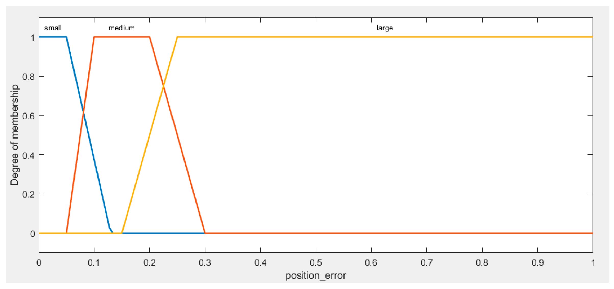
Position Error fuzzy sets (
Figure 2): trapezoid membership functions are used to define linguistic terms denoted as "Small Position Error," "Medium," and "Big." These terms are employed to represent position error values as follows:
For a more detailed analysis of position error within the [0, 1] range, we have organized it into three linguistic terms: "Small Position Error," "Medium Position Error," and "Large Position Error." "Small Position Error" encompasses values from 0 to 0.13, denoting precise positioning. "Medium Position Error" ranges from 0.05 to 0.3. Lastly, "Large Position Error" encompasses values from 0.15 to 1, representing situations where the level of positioning inaccuracy becomes more significant. This categorization enhances the accuracy of our analysis within the defined range and provides a more detailed understanding of position errors.
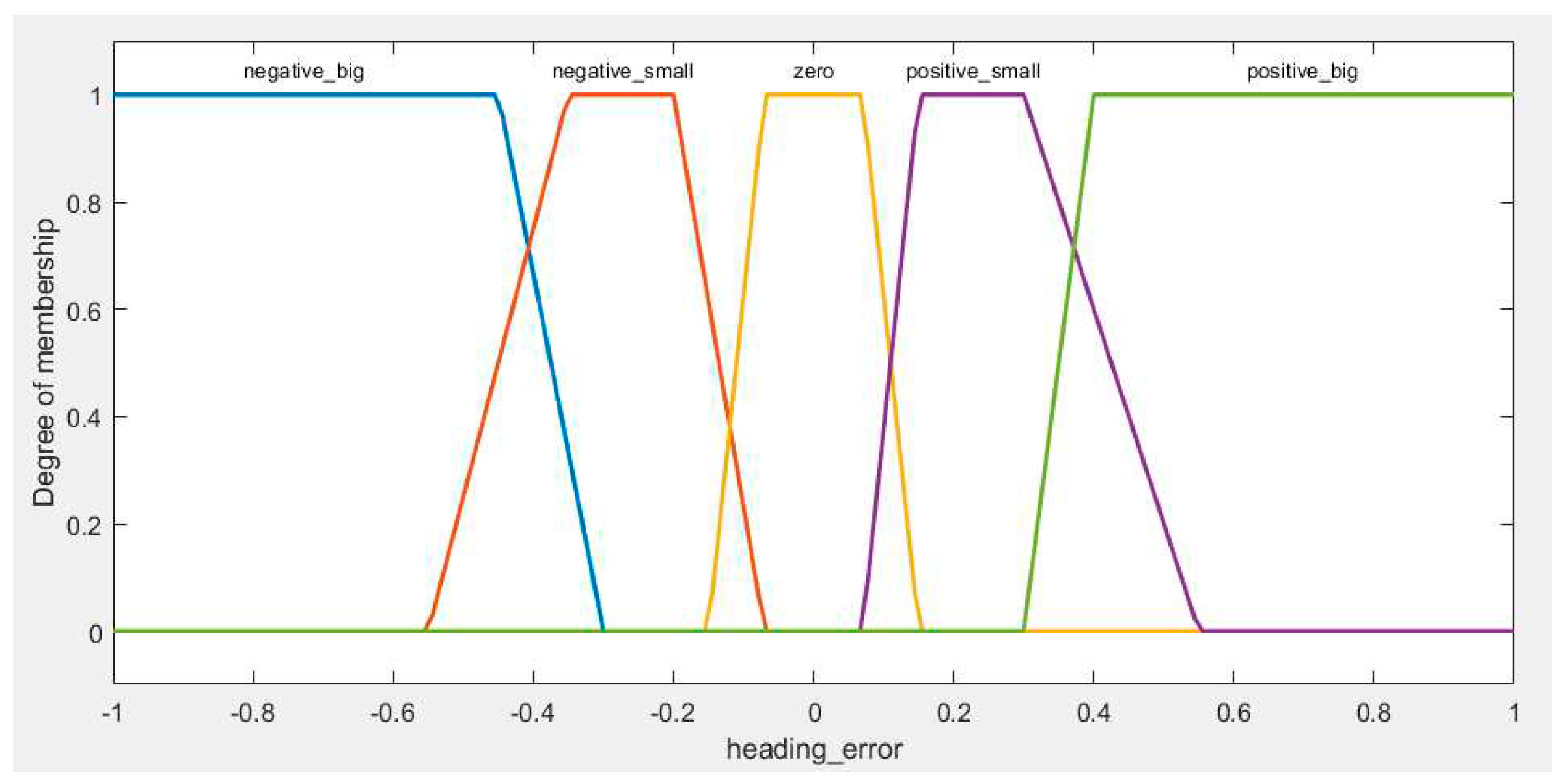
The same approach is applied to Heading Error, as shown in
Figure 3:
Within the scope of our research focused on AGV (Automated Guided Vehicle) navigation, we have taken a precise approach to categorizing the heading error range. These fuzzy sets are as follows: "Negative Big Heading Error" (ranging from -1 to -0.3), "Negative Small Heading Error" (spanning from -0.55 to -0.07), "Zero Heading Error" (encompassing values from -0.15 to 0.15), "Positive Small Heading Error" (extending from 0.07 to 0.55), and "Positive Big Heading Error" (ranging from 0.3 to 1).
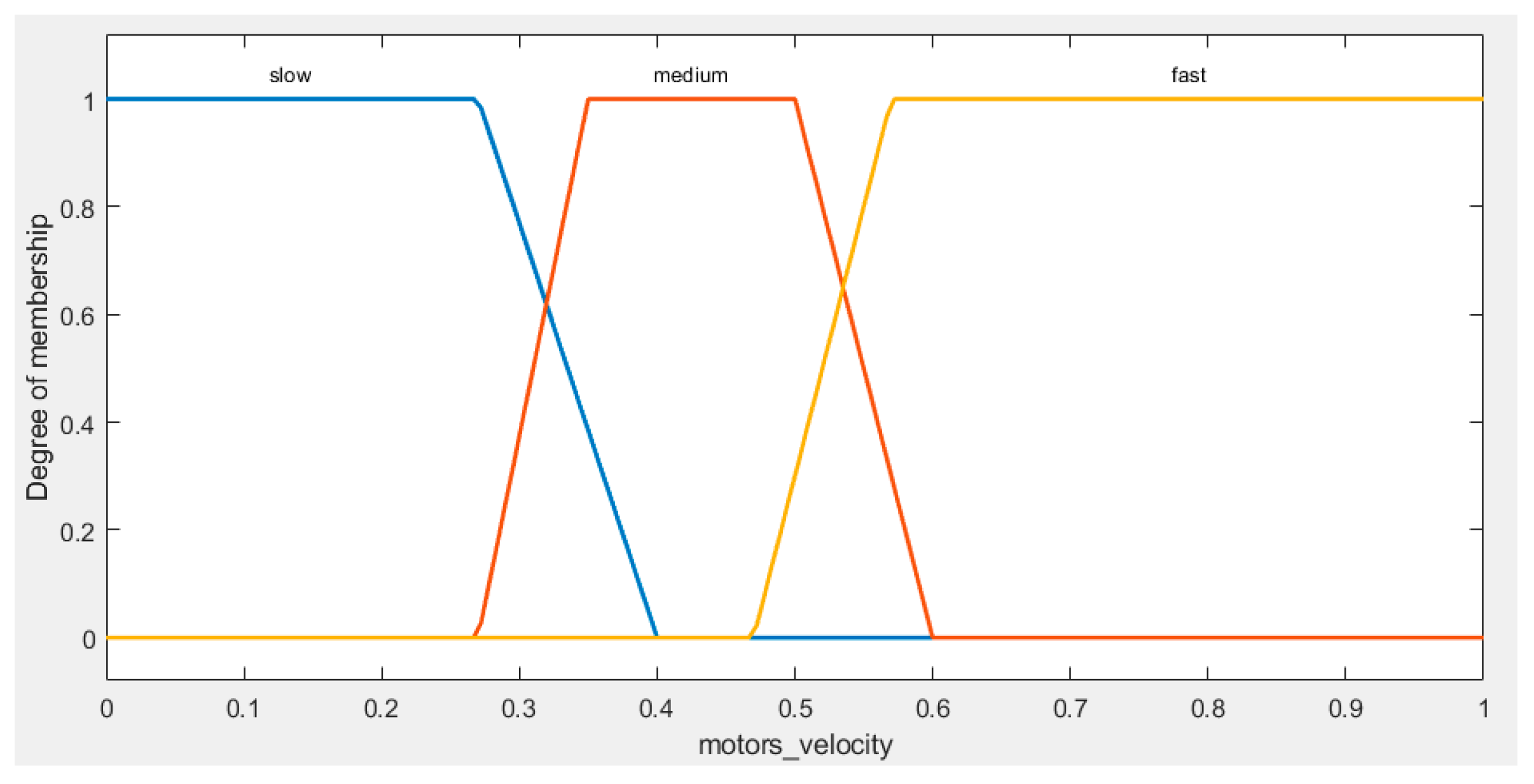
Figure 4 illustrates the fuzzy sets for the output (Velocity):
In our study, the output velocity of both the left and right motors play a crucial role in the performance of our AGV navigation system. For better understanding of the velocity output, we have categorized this range into three fuzzy sets: "Slow Velocity," covering values from 0 to 0.4, which represents slower motor speeds, "Medium Velocity," ranging from 0.27 to 0.6, indicating intermediate motor speeds, and "Fast Velocity," extending from 0.47 to 1, denoting higher motor speeds.
Based on our knowledge of the AGV navigation system, we have established a collection of expert rules that dictate the AGV's actions in diverse scenarios. This rule set serves as a crucial component of our navigation control strategy (
Table 1):
The training dataset has been generated in accordance with the expert logical rules described previously. These rules define the connections between position error, heading error, and motor velocities within the AGV navigation system. By following these rules, we have guaranteed that the training data comprehensively represents a wide spectrum of scenarios and behaviors, accurately capturing the AGV's responses to diverse error conditions. This dataset is fundamental for training the AGV navigation system and optimizing its performance. A sample of training data for the ANFIS tracking controller presented below in the
Table 2.
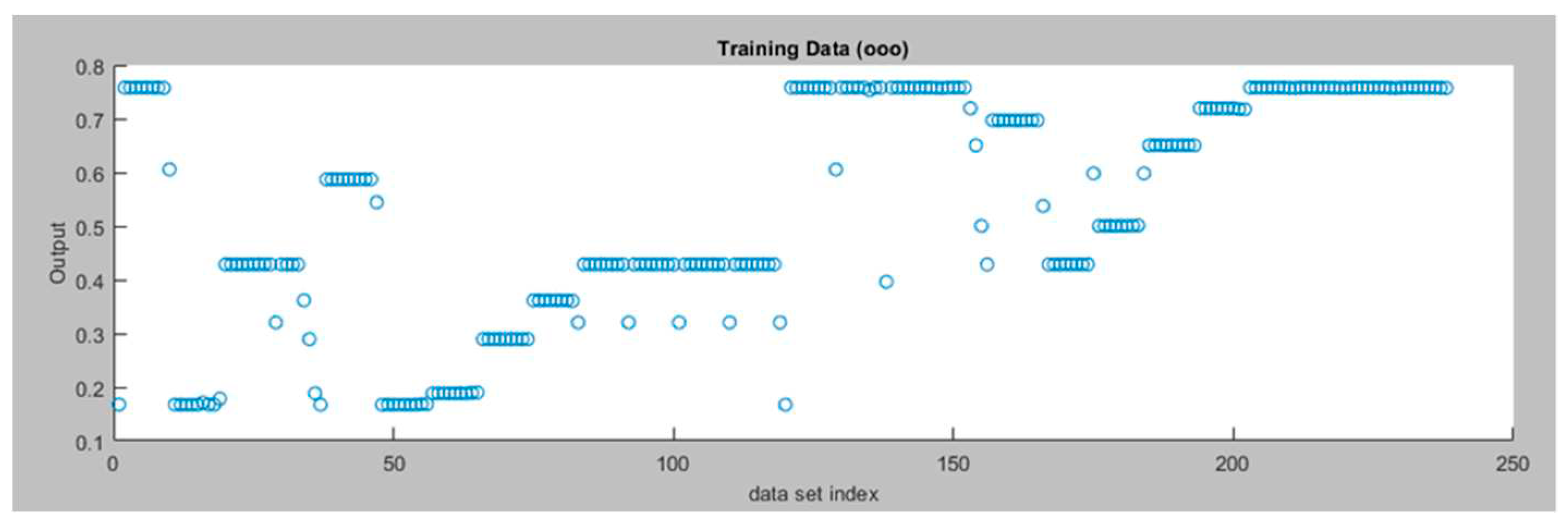
Figure 5 presents the Training Data for the Left Motor ANFIS tracking controller.
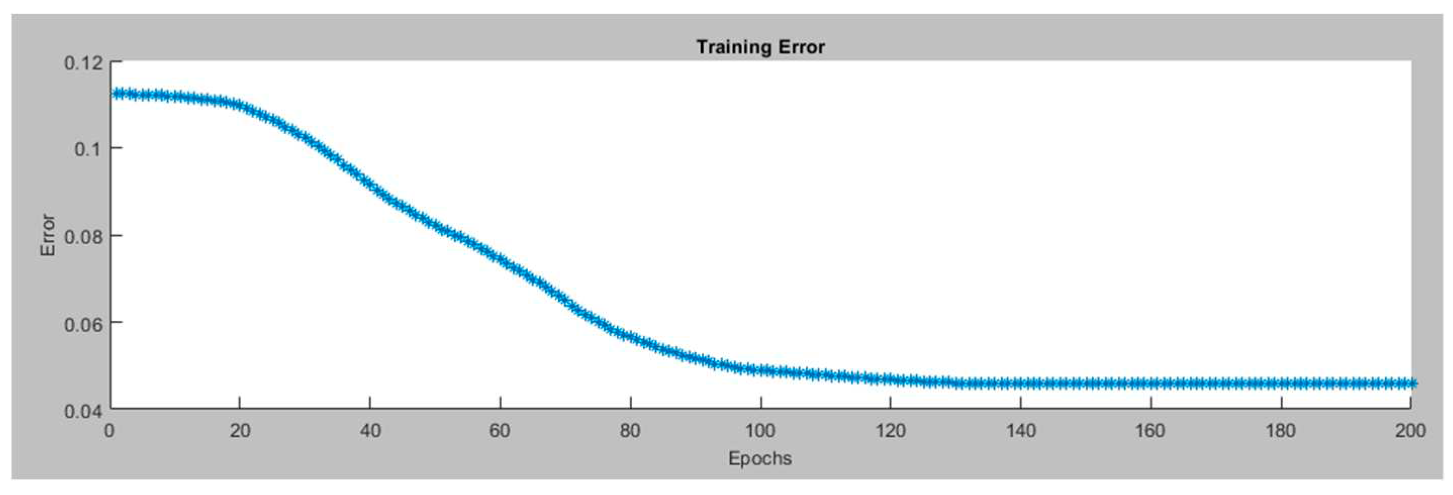
In the proposed ANFIS system setup, three membership functions have been used for each input. These functions are of the trapezoid type, which helps capture complex patterns. For the output, linear membership functions are chosen, ensuring straightforward mapping of rules. The system is generated using a grid partition approach for efficient input organization and a hybrid optimization method is applied during training to improve performance. Finally, the system is trained over 200 iterations (epochs). These settings make our system precise and adaptable for various robotics applications.
Figure 6 presents the training error for the Left Motor ANFIS tracking controller in the.
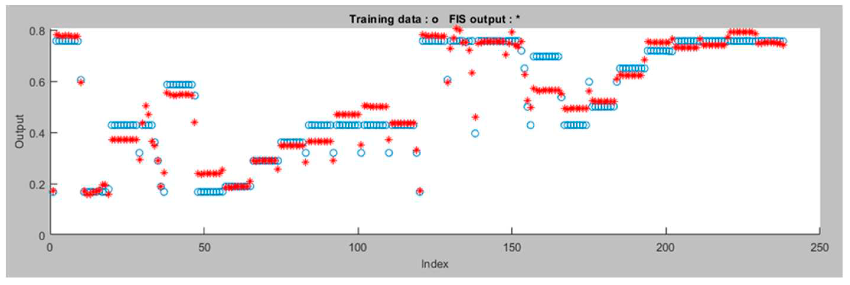
Figure 7 displays the data after the ANFIS is trained for the Left Motor ANFIS tracking controller. The proposed ANFIS model performed well during training with a minimal error of 0.045806. It has a total of 35 components, consisting of 27 linear and 24 nonlinear parameters. These components work together to make the model accurate and capable of handling complex data patterns. Additionally, the model uses 9 fuzzy rules to guide its decision-making. This ANFIS model is versatile and can be useful for various robotics applications.
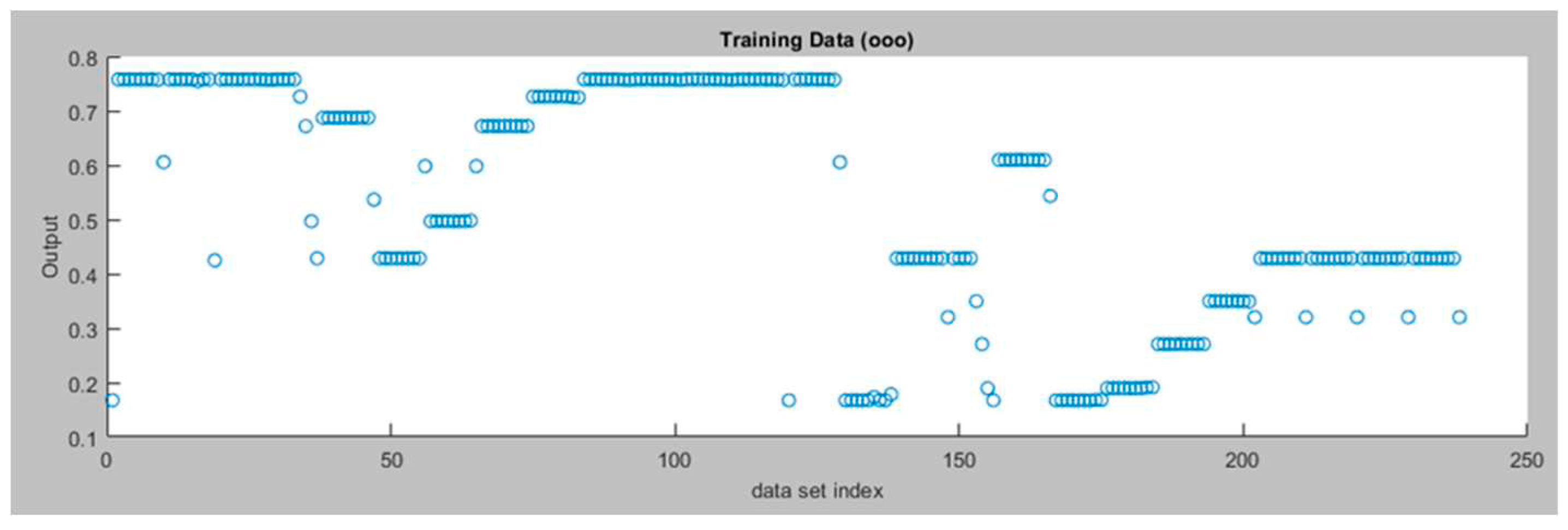
Figure 8 displays the training data for the right motor ANFIS tracking controller and
Figure 9 displays the training error for the right motor ANFIS tracking controller.
Figure 10 displays the data after the ANFIS is trained for the right motor ANFIS tracking controller. The proposed ANFIS model performed well during training with a minimal error of 0.046201. It uses a combination of 35 components, including 27 linear and 24 nonlinear parameters. This model consists of 9 fuzzy rules, enabling it to process data effectively for various robotics applications
4.3.2. ANFIS Avoidance Controller
The primary objective of the robot's obstacle avoidance controller is to navigate safely within its environment by avoiding collisions with obstacles. This controller is composed of two ANFIS controllers, one specifically governing the left motor and the other the right motor. Each controller takes two crucial inputs: the left sensor reading and the right sensor reading. These sensor values provide information about the proximity of obstacles on either side of the robot, with a range scaled from 0 to 1.
The output of each ANFIS controller corresponds to the velocity of the respective motor. These controllers collaboratively work to dynamically adapt motor velocities, enabling the robot to navigate around obstacles and maintain a collision-free path. By processing sensor data, the ANFIS controllers are capable of making real-time decisions regarding motor speeds, ensuring effective obstacle avoidance in the robot's navigation process. This mechanism enhances the robot's safety and reliability.
In this research, 32 data sets were chosen, based on expert knowledge, to be used in implementing the target-reaching controller, specifically for training the ANFIS system.
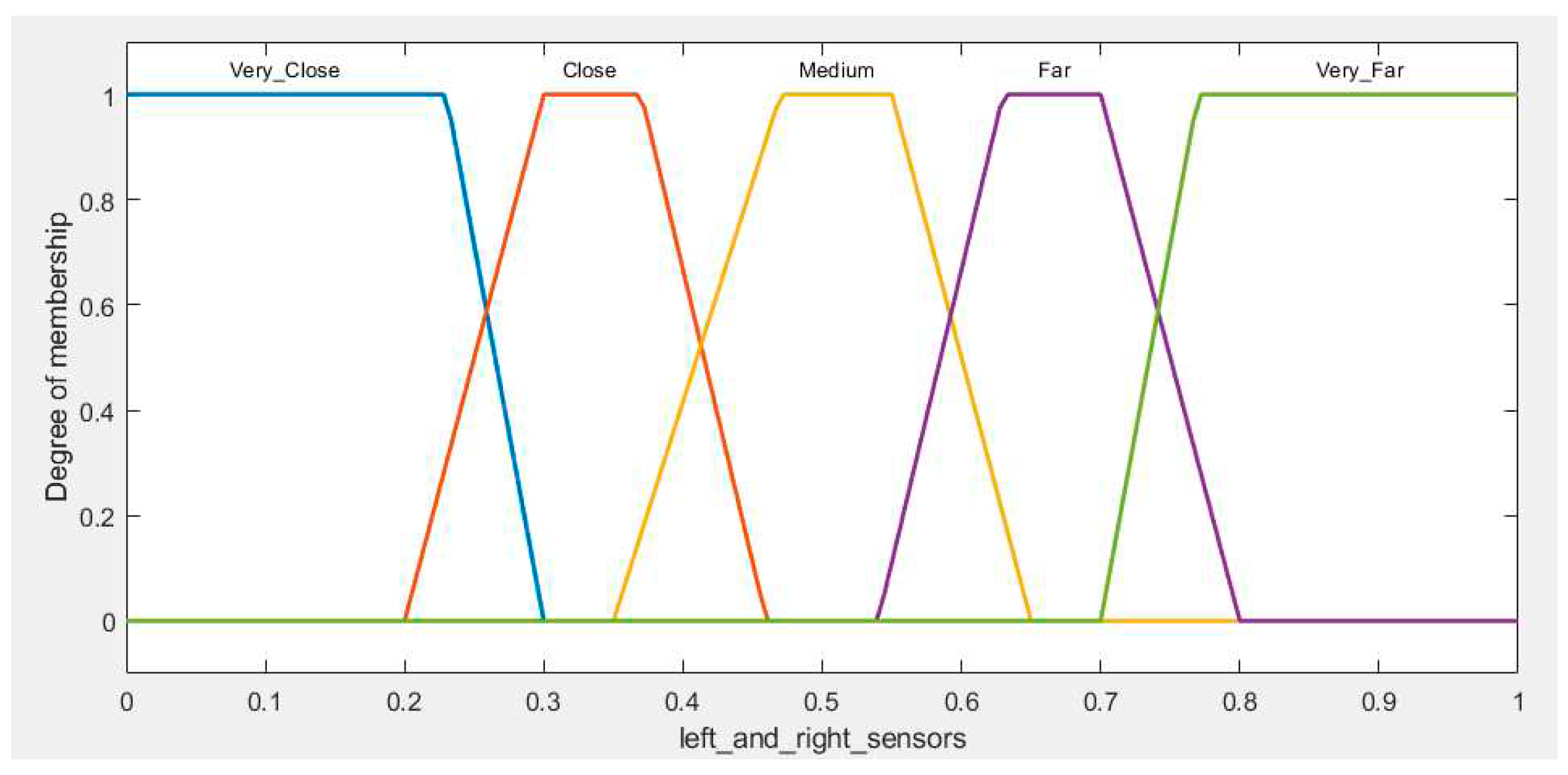
For the inputs (Left and Right Sensors), trapezoid membership functions are defined for the linguistic terms " Very Close" , " Close" , " Medium"," Far" , and " Very Far", as shown in
Figure 11.
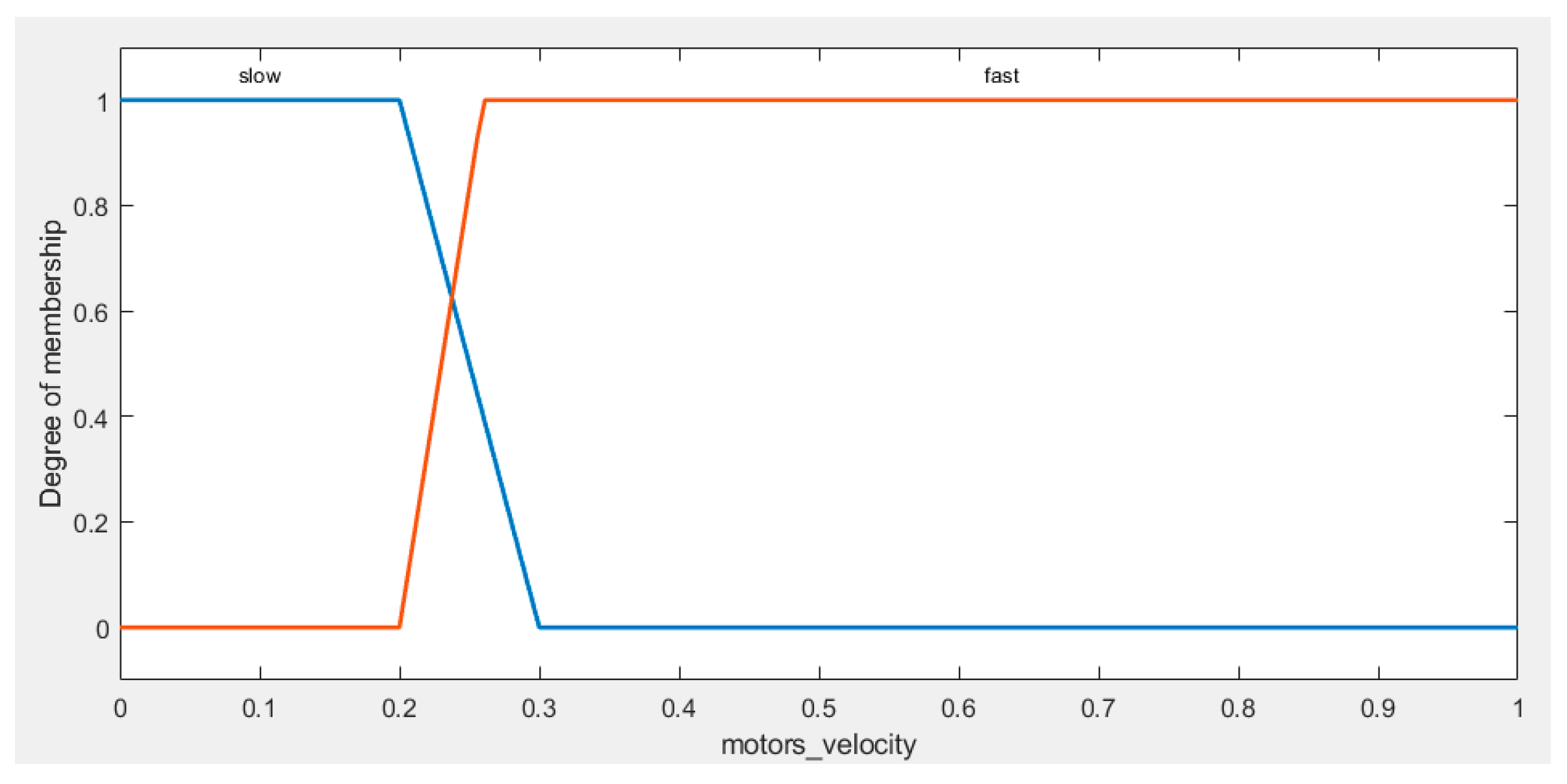
For the output (Left and Right Motor Velocity), the membership functions are presented in
Figure 12. Subsequently, a set of expert rules is established that dictate the behavior of the AGV in a variety of scenarios, as shown in
Table 3:
The training dataset has been rigorously generated in strict accordance with the expert logical rules presented in the
Table 4. These rules intricately define the relationship between the AGV's left and right sensors and the corresponding motor velocities. Following these rules, we have assembled a diverse dataset that encompasses a wide spectrum of scenarios and behaviors. This dataset comprehensively captures the subtle dynamics of the AGV's responses to varying sensor conditions, serving as a robust foundation for training the AGV's navigation system. Through this systematic approach, we ensure that our AGV is well-prepared to navigate and adapt to real-world situations, thereby delivering efficient and reliable performance.
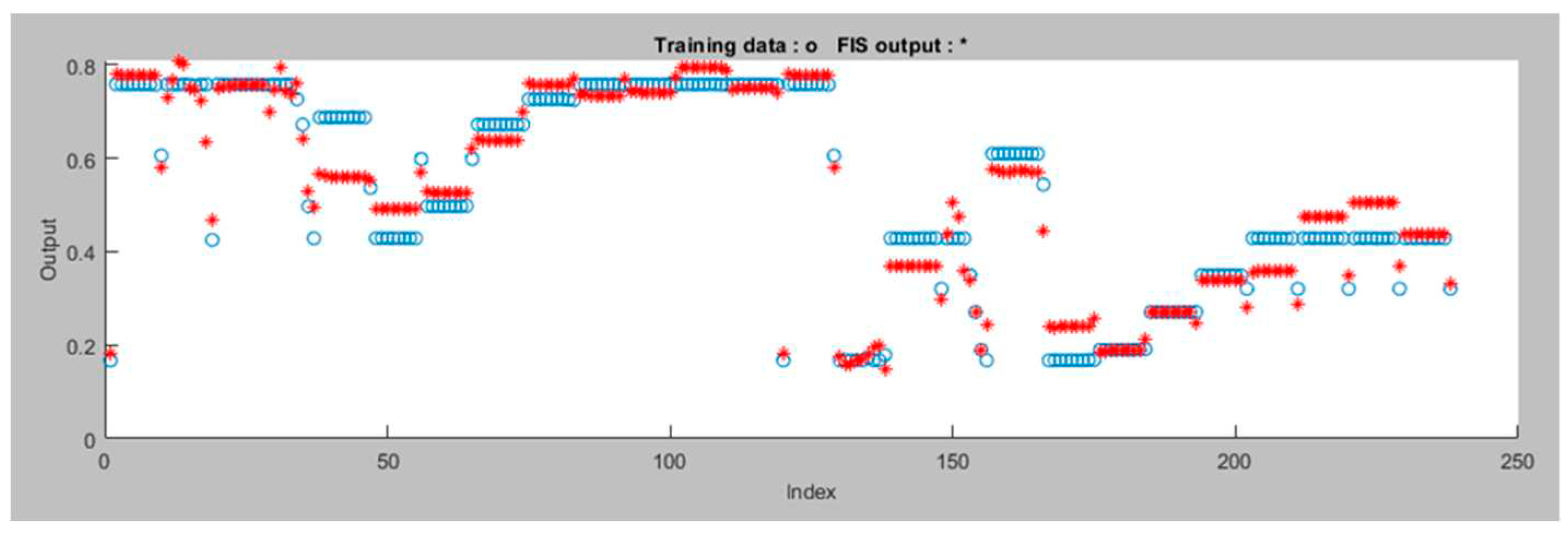
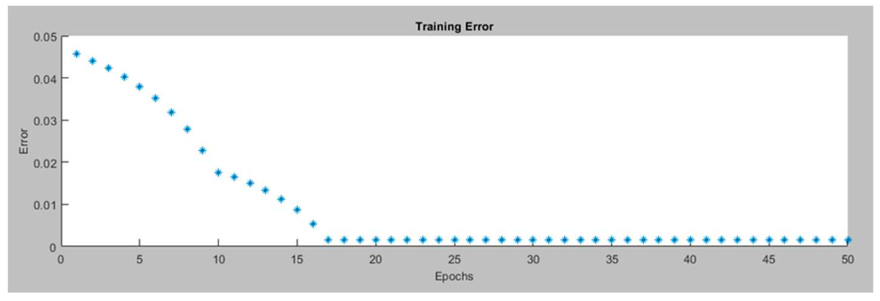
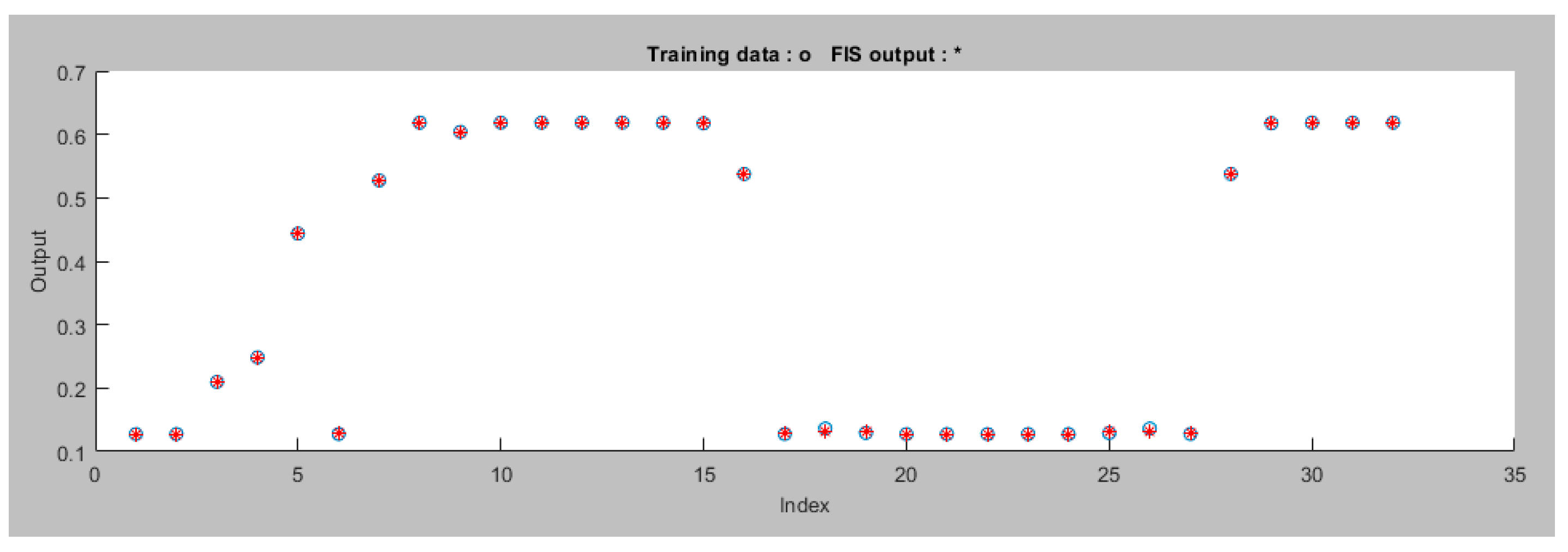
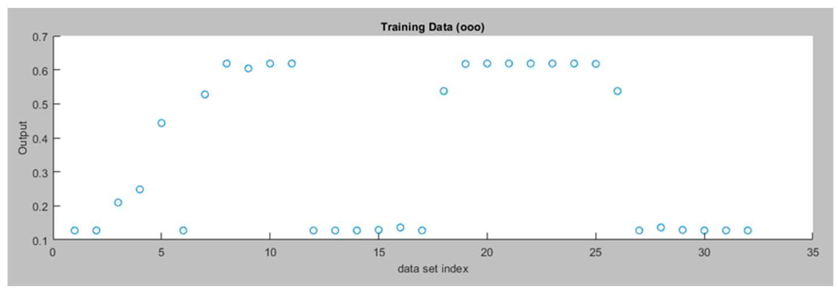
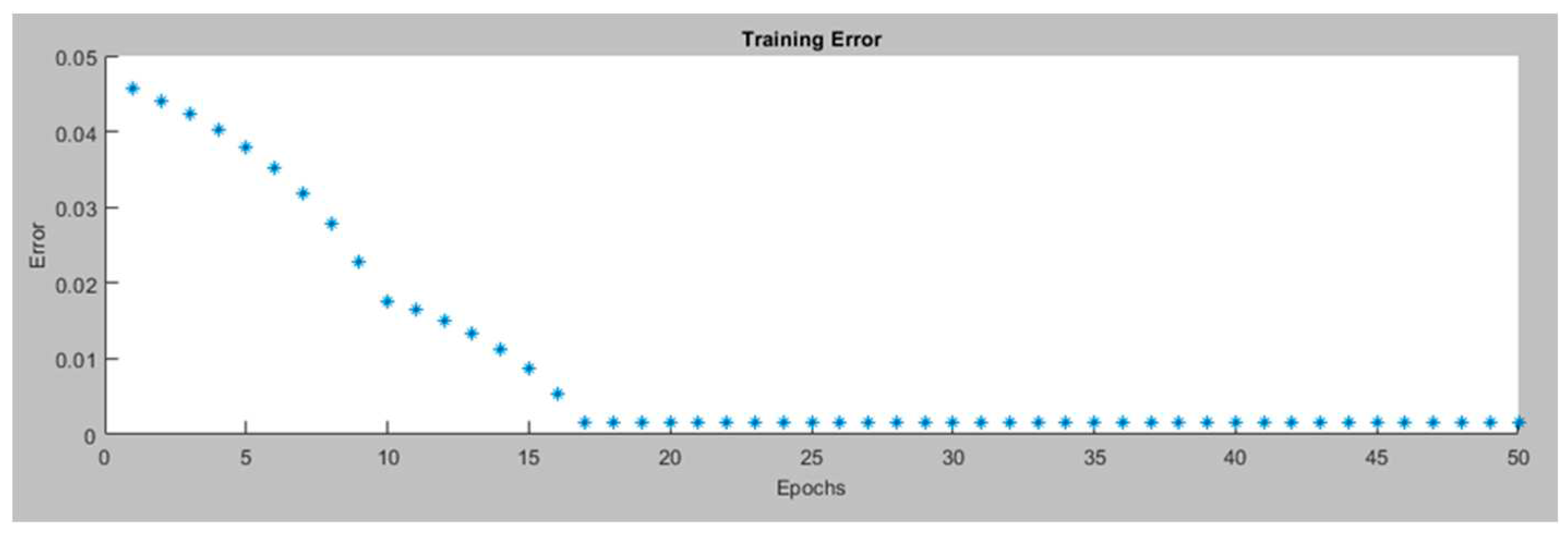
Figure 13 displays the training data for the left motor ANFIS avoidance controller. In our ANFIS model, we used four membership functions for each input with trapezoid shapes. The output membership functions are linear. The Fuzzy Inference System is created using grid partitioning and the hybrid optimization method is applied. The model was trained over 50 epochs.
Figure 14 depicts the Training error for the left motor ANFIS avoidance controller.
Figure 15 displays the data after the ANFIS is trained for the left motor ANFIS Controller. In this ANFIS model, we achieve a minimal training RMSE of 0.001669. The model utilizes 53 nodes with a combination of 48 linear and 32 nonlinear parameters, totaling 80 parameters. This model consists of 16 fuzzy rules
The same approach is applied to right motor,
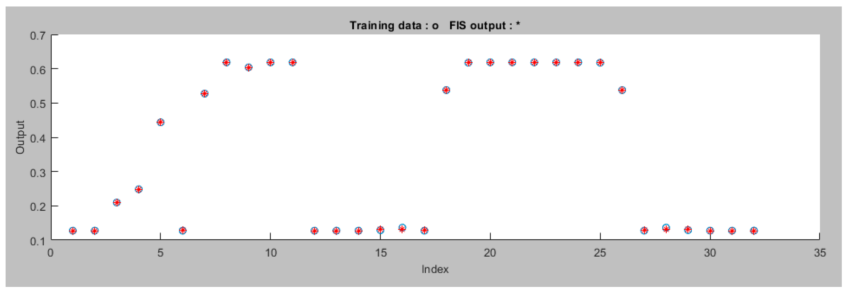
Figure 16 displays the training data for the right motor ANFIS avoidance controller and
Figure 17 displays the training error for the right motor ANFIS avoidance controller.
Figure 18 displays the data after the ANFIS is trained for the right motor ANFIS avoidance controller. In this ANFIS model, a minimal training RMSE of 0.001670 is achieved. The model utilizes 53 nodes with a combination of 48 linear and 32 nonlinear parameters, totaling 80 parameters. This model consists of 16 fuzzy rules
5. Simulation Results
The experimentation was carried out through the utilization of a robot simulator, specifically employing CoppeliaSim, to configure a simulated robotic environment. The mobile robot chosen for this research is the Pioneer p_3dx, a compact two-wheel differential-drive robot, notable for its integration of 16 ultrasonic sensors. In this study, an effort is made to simplify the complexity of the ANFIS obstacle avoidance controller by exclusively utilizing the six frontal sensors, organized into two sets.
The determination of the right and left sensor values is computed as follows:
Right Sensor Value = ((Measurement from Sensor 1 + Measurement from Sensor 2 + Measurement from Sensor 3)) / 3
Left Sensor Value = ((Measurement from Sensor 4 + Measurement from Sensor 5 + Measurement from Sensor 6)) / 3
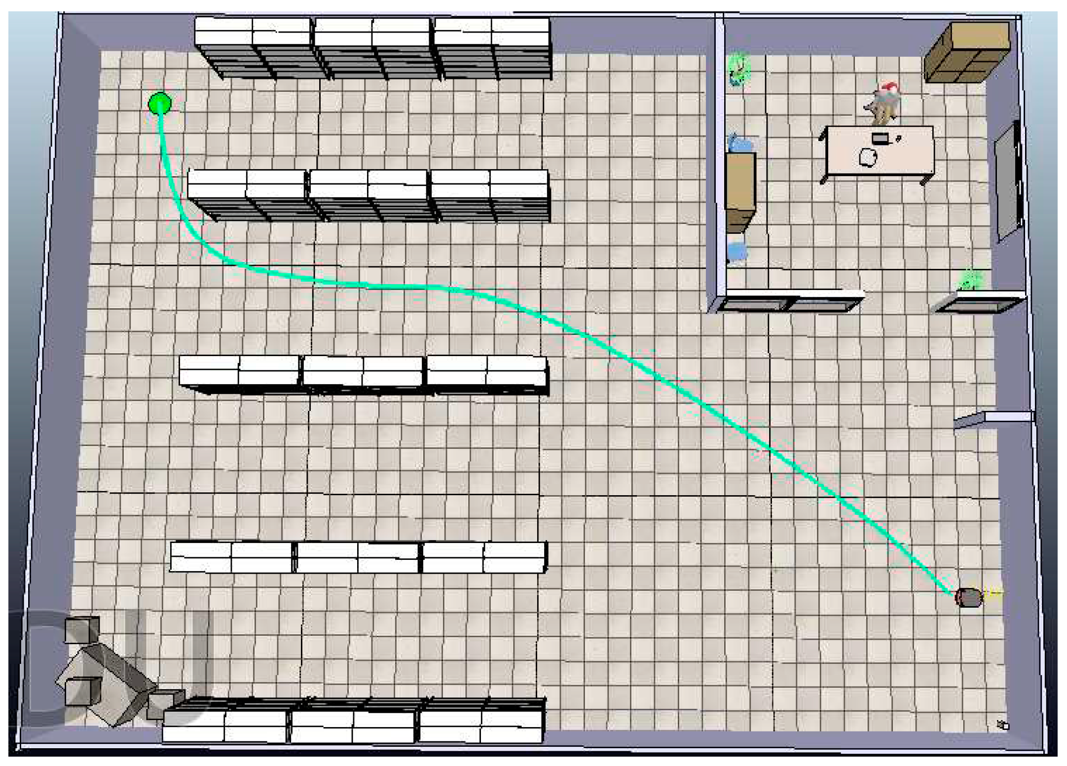
Initially, the Bump-Surface concept is employed to ascertain the shortest and optimal path between the robot's initial point and its designated endpoint.
Figure 19 presents the optimal path computed using a path planning algorithm in green color.
Subsequently, a vector P is formulated, encompassing the (x, y) coordinates that necessitate the robot's traversal for reaching the target point. The ANFIS tracking controller is then deployed to facilitate the robot's transition from one point to another within vector P. Hence, as the robot arrives at each point within vector P, it proceeds to advance toward the subsequent point, persisting in this manner until it attains the final target point, symbolized as a green circle (
Figure 19).
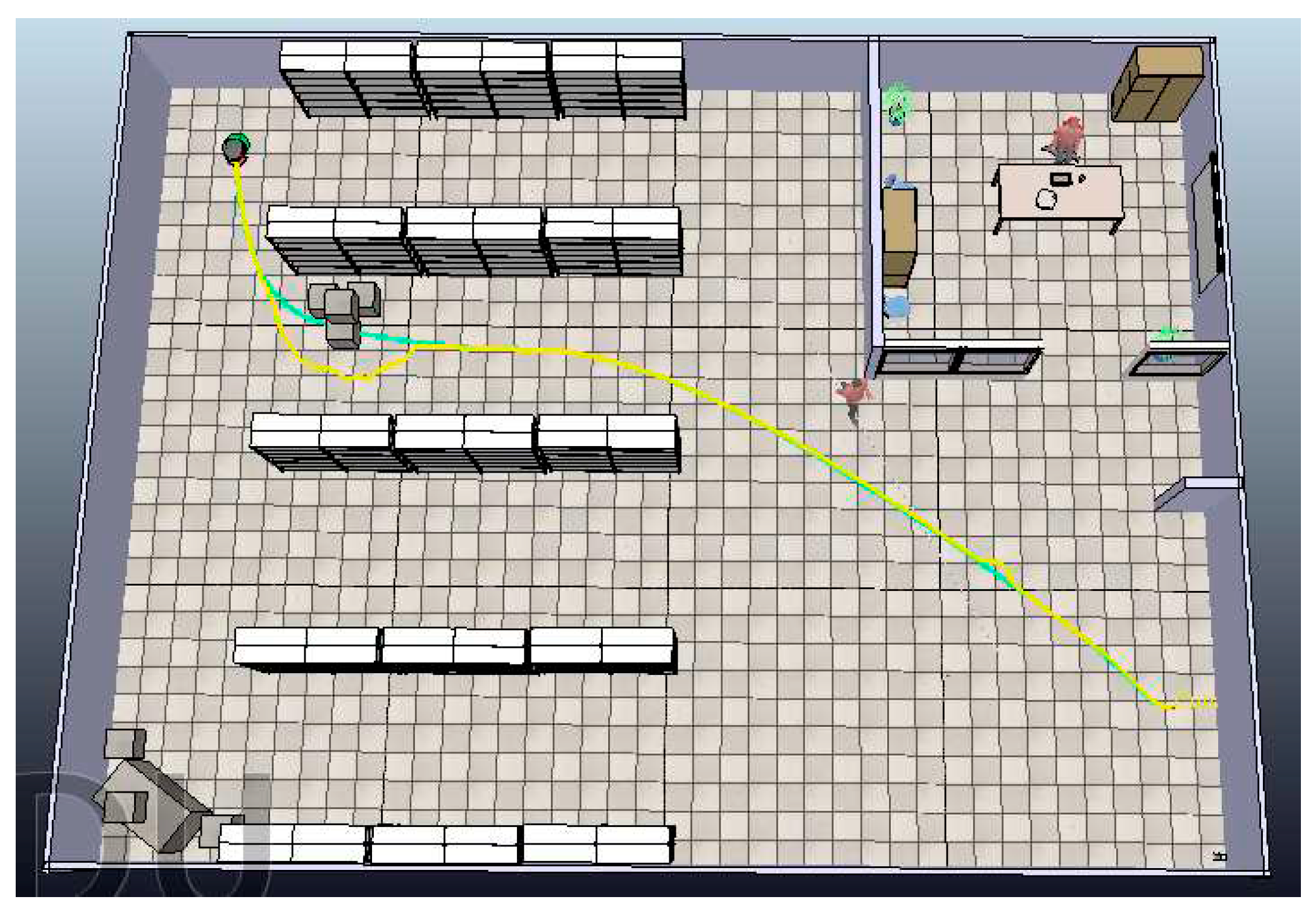
In our scenario, we deal with the presence of two types of obstacles: a dynamic one, represented by a moving human, and static obstructions in the form of paper boxes. The path planning algorithm, designed to identify the shortest route, leverages the Bump-surface concept, ensuring that the robot can navigate with smooth and efficient turns. Furthermore, an ANFIS tracking controller is employed to guide the robot along this predefined trajectory.
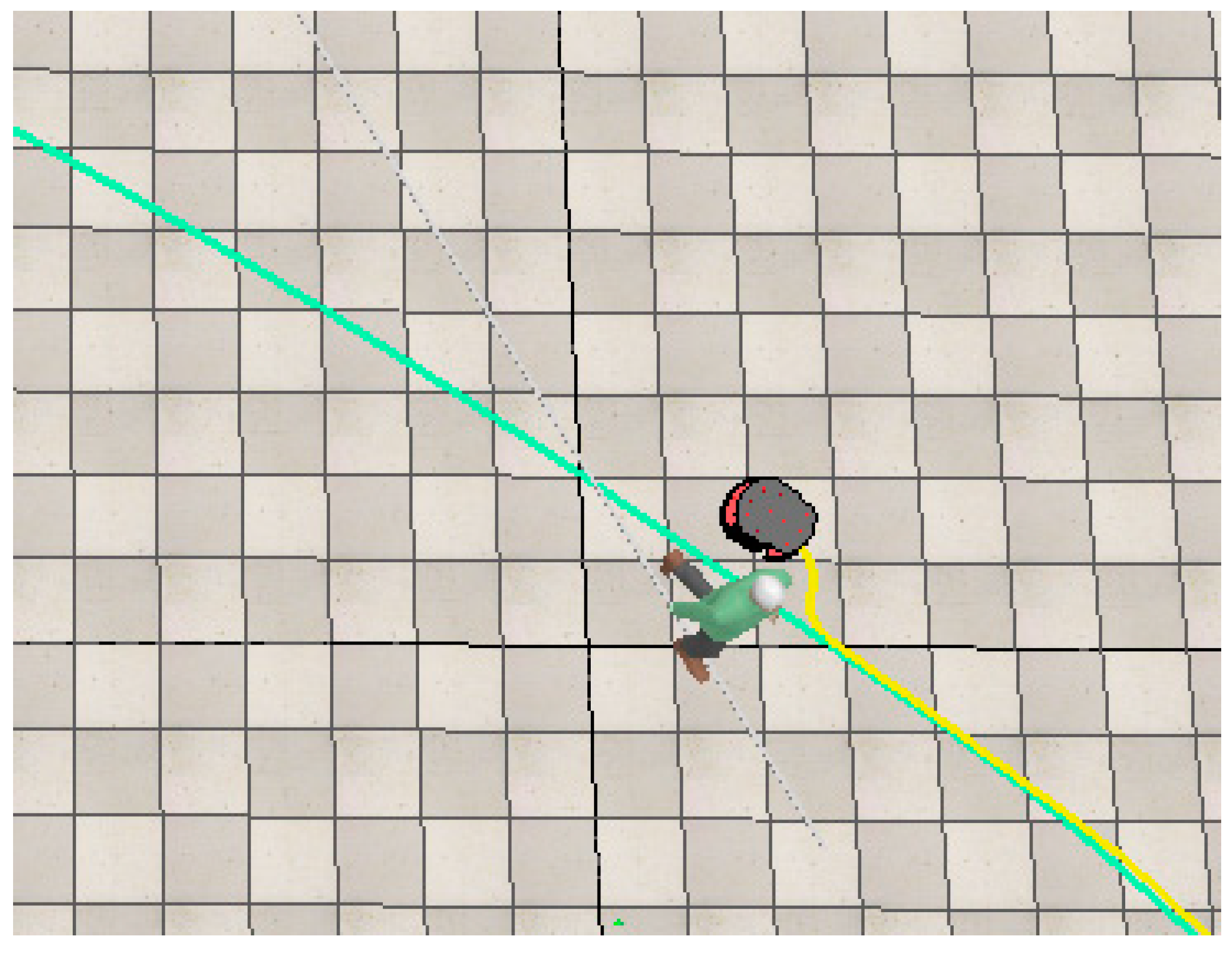
While the robot is in motion, it remains alert for any approaching humans, at which point the ANFIS avoidance controller is activated. This specialized controller dictates the robot's response to potential collision threats. In such instances, the robot executes a maneuver, temporarily diverting from its pre-established path to evade a collision with the moving human as it approaches the target. Once the risk of collision disappears, the robot promptly reverts to its original path, allowing it to continue its progress toward the designated target. A similar process takes place when the robot identifies a static obstacle.
In the provided images
Figure 20 and
Figure 21, the green line corresponds to the path generated by the path planning algorithm, while the yellow line represents the actual path taken by the robot to navigate around obstacles and reach the target destination.
6. Conclusions
In this research, we present a path planning algorithm in conjunction with an ANFIS-based approach for addressing the challenge of robot navigation within uncertain and dynamic environments while ensuring effective obstacle avoidance. Our primary objective is to design an ANFIS control model for mobile robots operating within dynamic environments, focusing on achieving both smooth and safe navigation, while also considering distance optimization.
The combined path planning algorithm and ANFIS control strategy synergistically guarantee collision-free and seamless navigation. Our control system is comprised of two ANFIS controllers. An ANFIS tracking controller, steers the robot towards its target. When an obstacle is detected, the ANFIS avoidance controller comes into action to evade the obstruction.
Simulation results demonstrate the efficacy of our approach in generating collision-free navigation paths as the mobile robot adeptly maneuvers through its surroundings, avoiding both static and moving obstacles with the aid of ultrasonic sensors. These outcomes underscore the synergistic advantages gained from integrating path planning and ANFIS, allowing the robot to reach its target along the shortest, smoothest path while ensuring avoidance of collisions with both static and moving obstacles.
Author Contributions
Conceptualization, S.S. and P.Z.; methodology, S.S.; software, S.S.; validation, S.S.; formal analysis, S.S. and P.Z.; investigation, S.S. and P.Z.; resources, S.S.; data curation, S.S.; writing—original draft preparation, S.S. and P.Z.; writing—review and editing, S.S. and P.Z.; visualization, S.S. and P.Z.; supervision, P.Z. All authors have read and agreed to the published version of the manuscript
Funding
This research received no external funding.
Data Availability Statement
Data sharing not applicable.
Conflicts of Interest
The authors declare no conflict of interest.
References
- Pratama, P.S.; Jeong, S.K.; Park, S.S.; Kim, S.B. Moving Object Tracking and Avoidance Algorithm for Differential Driving AGV Based on Laser Measurement Technology. Int. J. Sci. Eng. 2013, 4(1), 11–15. [Google Scholar] [CrossRef]
- Ito, S.; Hiratsuk,a S.; Ohta, M.; Matsubara, H.; Ogawa, M. Small Imaging Depth LIDAR and DCNN-Based Localization for Automated Guided Vehicle. Sensors 2018, 18, 177. [CrossRef]
- Rozsa, Z.; Sziranyi, T. Obstacle Prediction for Automated Guided Vehicles Based on Point Clouds Measured by a Tilted LIDAR Sensor. IEEE T Intell Transp 2018, 19(8), 2708–2720. [Google Scholar] [CrossRef]
- Lee, J.; Hyun, C.-H.; Park, M. A Vision-Based Automated Guided Vehicle System with Marker Recognition for Indoor Use. Sensors 2013, 13, 10052–10073. [Google Scholar] [CrossRef] [PubMed]
- Al-Mayyahi, A.; Wang, W.; Birch, P. Adaptive Neuro-Fuzzy Technique for Autonomous Ground Vehicle Navigation. Robotics 2014, 3, 349–370. [Google Scholar] [CrossRef]
- Miao, Z.; Zhang, X.; Huang, G. Research on Dynamic Obstacle Avoidance Path Planning Strategy of AGV. J. Phys.: Conf. Ser. 2021, 2006, 012067, 10.1088/1742-6596/2006/1/012067. [Google Scholar] [CrossRef]
- Haider, M.H.; Wang, Z.; Khan, A.A.; Ali, H.; Zheng, H.; Usman, S.; Kumar, R.; Usman Maqbool Bhutta, M.; Zhi, P. Robust mobile robot navigation in cluttered environments based on hybrid adaptive neuro-fuzzy inference and sensor fusion. Journal of King Saud University - Computer and Information Sciences 2022, 34, 9060–9070. [Google Scholar] [CrossRef]
- Farahat, H.; Farid, S.; Mahmoud, O.E. Adaptive Neuro-Fuzzy control of Autonomous Ground Vehicle (AGV) based on Machine Vision. Engineering Research Journal 2019, 163, 218–233. [Google Scholar] [CrossRef]
- Jung, K.; Lee, I.; Song,H.; Kim, J.; Kim, S. Vision Guidance System for AGV Using ANFIS. Proceedings of the 5th International Conference on Intelligent Robotics and Applications - Volume Part I, 2012. [CrossRef]
- Khelchandra, T.; Huang, J.; Debnath, S. Path planning of mobile robot with neuro-genetic-fuzzy technique in static environment. International Journal of Hybrid Intelligent Systems 2014, 11, 71–80. [Google Scholar] [CrossRef]
- Faisal, M.; Hedjar, R.; Al Sulaiman, M.; Al-Mutib, K. Fuzzy Logic Navigation and Obstacle Avoidance by a Mobile Robot in an Unknown Dynamic Environment. Int J Adv Robot Syst 2013, 1–7. [Google Scholar] [CrossRef]
- Dudek, G.; Jenkin, M. Computational Principles of Mobile Robotics (2nd ed.). Cambridge University Press, USA, 2010.
- Gul, F.; Rahiman, W.; Sahal Nazli Alhady, S. A comprehensive study for robot navigation techniques. Cogent Engineering, 2019, 6, 1–25. [Google Scholar] [CrossRef]
- Azariadis, P.; Aspragathos, N. Obstacle representation by Bump-Surfaces for optimal motion-planning. Journal of Robotics and Autonomous Systems 2005, 51(2–3), 129–150. [Google Scholar] [CrossRef]
- Jang J.-S., R. ANFIS Adaptive-Network-based Fuzzy Inference System. IEEE T Syst Man Cyb 1993, 23(3), 665–685. [Google Scholar] [CrossRef]
Figure 1.
A visual depiction of the robot within both the global and local reference frames.
Figure 1.
A visual depiction of the robot within both the global and local reference frames.
Figure 2.
Position error fuzzy sets.
Figure 2.
Position error fuzzy sets.
Figure 3.
Heading error fuzzy sets.
Figure 3.
Heading error fuzzy sets.
Figure 4.
Output fuzzy sets.
Figure 4.
Output fuzzy sets.
Figure 5.
Training Data for the Left Motor ANFIS Tracking Controller.
Figure 5.
Training Data for the Left Motor ANFIS Tracking Controller.
Figure 6.
Training Error for Left Motor ANFIS Tracking Controller.
Figure 6.
Training Error for Left Motor ANFIS Tracking Controller.
Figure 7.
Data after the ANFIS is trained (Left Motor ANFIS Tracking Controller).
Figure 7.
Data after the ANFIS is trained (Left Motor ANFIS Tracking Controller).
Figure 8.
Training Data for the Right Motor ANFIS Tracking Controller.
Figure 8.
Training Data for the Right Motor ANFIS Tracking Controller.
Figure 9.
Training Error for Right Motor (ANFIS Tracking Controller).
Figure 9.
Training Error for Right Motor (ANFIS Tracking Controller).
Figure 10.
Data after the ANFIS is trained (Left Motor ANFIS Tracking Controller).
Figure 10.
Data after the ANFIS is trained (Left Motor ANFIS Tracking Controller).
Figure 11.
Fuzzy sets for the inputs.
Figure 11.
Fuzzy sets for the inputs.
Figure 12.
Fuzzy sets for the output.
Figure 12.
Fuzzy sets for the output.
Figure 13.
Training Data for the Left Motor Velocity (ANFIS Avoidance Controller).
Figure 13.
Training Data for the Left Motor Velocity (ANFIS Avoidance Controller).
Figure 14.
Training Error for Left Motor Velocity (ANFIS Avoidance Controller).
Figure 14.
Training Error for Left Motor Velocity (ANFIS Avoidance Controller).
Figure 15.
Data after the ANFIS is trained (Left Motor ANFIS Avoidance Controller).
Figure 15.
Data after the ANFIS is trained (Left Motor ANFIS Avoidance Controller).
Figure 16.
Training Data for the Right Motor (ANFIS Avoidance Controller).
Figure 16.
Training Data for the Right Motor (ANFIS Avoidance Controller).
Figure 17.
Training Error for Right Motor (ANFIS Avoidance Controller).
Figure 17.
Training Error for Right Motor (ANFIS Avoidance Controller).
Figure 18.
Data after the ANFIS is trained (Right Motor ANFIS Avoidance Controller).
Figure 18.
Data after the ANFIS is trained (Right Motor ANFIS Avoidance Controller).
Figure 19.
Optimal path computed using a path planning algorithm.
Figure 19.
Optimal path computed using a path planning algorithm.
Figure 20.
The robot executes a maneuver to avoid a dynamic obstacle.
Figure 20.
The robot executes a maneuver to avoid a dynamic obstacle.
Figure 21.
The robot effectively navigates by avoiding all encountered obstacles to successfully reach its designated target destination.
Figure 21.
The robot effectively navigates by avoiding all encountered obstacles to successfully reach its designated target destination.
Table 1.
Rule set for ANFIS tracking controller training data.
Table 1.
Rule set for ANFIS tracking controller training data.
| Rule |
Position Error |
Heading Error |
Right Motor Velocity |
Left Motor Velocity |
| 1 |
Large |
Negative Big |
Medium |
Fast |
| 2 |
Large |
Negative Small |
Slow |
Medium |
| 3 |
Large |
Zero |
Fast |
Fast |
| 4 |
Large |
Positive Small |
Medium |
Slow |
| 5 |
Large |
Positive Big |
Fast |
Medium |
| 6 |
Medium |
Negative Big |
Medium |
Fast |
| 7 |
Medium |
Negative Small |
Slow |
Medium |
| 8 |
Medium |
Zero |
Fast |
Fast |
| 9 |
Medium |
Positive Small |
Medium |
Slow |
| 10 |
Medium |
Positive Big |
Fast |
Medium |
| 11 |
Small |
Negative Big |
Slow |
Fast |
| 12 |
Small |
Negative Small |
Slow |
Fast |
| 13 |
Small |
Zero |
Slow |
Slow |
| 14 |
Small |
Positive Small |
Fast |
Slow |
| 15 |
Small |
Positive Big |
Fast |
Slow |
Table 2.
Sample of training data for the ANFIS tracking controller.
Table 2.
Sample of training data for the ANFIS tracking controller.
| Position Error |
Heading Error |
Expected Right Motor Velocity |
Expected Left Motor Velocity |
| 0.9 |
0 |
0.7578 |
0.7578 |
| 0.8 |
0 |
0.7578 |
0.7578 |
| 0.7 |
0 |
0.7578 |
0.7578 |
| 0.6 |
0 |
0.7578 |
0.7578 |
| 0.5 |
0 |
0.7578 |
0.7578 |
| 0.4 |
0 |
0.7578 |
0.7578 |
| 0.3 |
0 |
0.7578 |
0.7578 |
| 0.2 |
0 |
0.7572 |
0.7572 |
| 0.1 |
0 |
0.6055 |
0.6055 |
| 0 |
0.9 |
0.7578 |
0.1674 |
| 0 |
0.8 |
0.7578 |
0.1674 |
| 0 |
0.7 |
0.7578 |
0.1674 |
| 0 |
0.6 |
0.7578 |
0.1674 |
| 0 |
0.5 |
0.7578 |
0.1674 |
| 0 |
0.4 |
0.7546 |
0.1713 |
Table 3.
Rule set for ANFIS avoidance controller training data.
Table 3.
Rule set for ANFIS avoidance controller training data.
| Rule |
Left Sensor |
Right Sensor |
Right Motor Velocity |
Left Motor Velocity |
| 1 |
Very Close |
Very Close |
Slow |
Slow |
| 2 |
Very Close |
Close |
Slow |
Fast |
| 3 |
Very Close |
Medium |
Slow |
Fast |
| 4 |
Very Close |
Far |
Slow |
Fast |
| 5 |
Very Close |
Very Far |
Slow |
Fast |
| 6 |
Close |
Very Close |
Fast |
Slow |
| 7 |
Close |
Close |
Slow |
Slow |
| 8 |
Close |
Medium |
Slow |
Fast |
| 9 |
Close |
Far |
Slow |
Fast |
| 10 |
Close |
Very Far |
Slow |
Fast |
| 11 |
Medium |
Very Close |
Fast |
Slow |
| 12 |
Medium |
Close |
Fast |
Slow |
| 13 |
Medium |
Medium |
Slow |
Slow |
| 14 |
Medium |
Far |
Slow |
Fast |
| 15 |
Medium |
Very Far |
Slow |
Fast |
| 16 |
Far |
Very Close |
Fast |
Slow |
| 17 |
Far |
Close |
Fast |
Slow |
| 18 |
Far |
Medium |
Fast |
Slow |
| 19 |
Far |
Far |
Fast |
Fast |
| 20 |
Far |
Very Far |
Slow |
Fast |
| 21 |
Very Far |
Very Close |
Fast |
Slow |
| 22 |
Very Far |
Close |
Fast |
Slow |
| 23 |
Very Far |
Medium |
Fast |
Slow |
| 24 |
Very Far |
Far |
Fast |
Slow |
| 25 |
Very Far |
Very Far |
Fast |
Fast |
Table 4.
Sample of training data for the ANFIS avoidance controller.
Table 4.
Sample of training data for the ANFIS avoidance controller.
| Left Sensor |
Right Sensor |
Expected Right Motor Velocity |
Expected Left Motor Velocity |
| 0 |
1 |
0.6186 |
0.1276 |
| 0.1 |
0.9 |
0.6186 |
0.1276 |
| 0.2 |
0.8 |
0.6186 |
0.1276 |
| 0.3 |
0.7 |
0.6175 |
0.1292 |
| 0.4 |
0.6 |
0.5377 |
0.1364 |
| 0.5 |
0.5 |
0.1276 |
0.1276 |
| 0.6 |
0.4 |
0.1363 |
0.5377 |
| 0.7 |
0.3 |
0.1292 |
0.6175 |
| 0.8 |
0.2 |
0.1276 |
0.6186 |
| 0.9 |
0.1 |
0.1276 |
0.6186 |
| 1 |
0 |
0.1276 |
0.6186 |
|
Disclaimer/Publisher’s Note: The statements, opinions and data contained in all publications are solely those of the individual author(s) and contributor(s) and not of MDPI and/or the editor(s). MDPI and/or the editor(s) disclaim responsibility for any injury to people or property resulting from any ideas, methods, instructions or products referred to in the content. |
© 2023 by the authors. Licensee MDPI, Basel, Switzerland. This article is an open access article distributed under the terms and conditions of the Creative Commons Attribution (CC BY) license (http://creativecommons.org/licenses/by/4.0/).
