Submitted:
17 October 2023
Posted:
19 October 2023
You are already at the latest version
Abstract
Keywords:
1. Introduction
2. Experimental
2.1. Materials
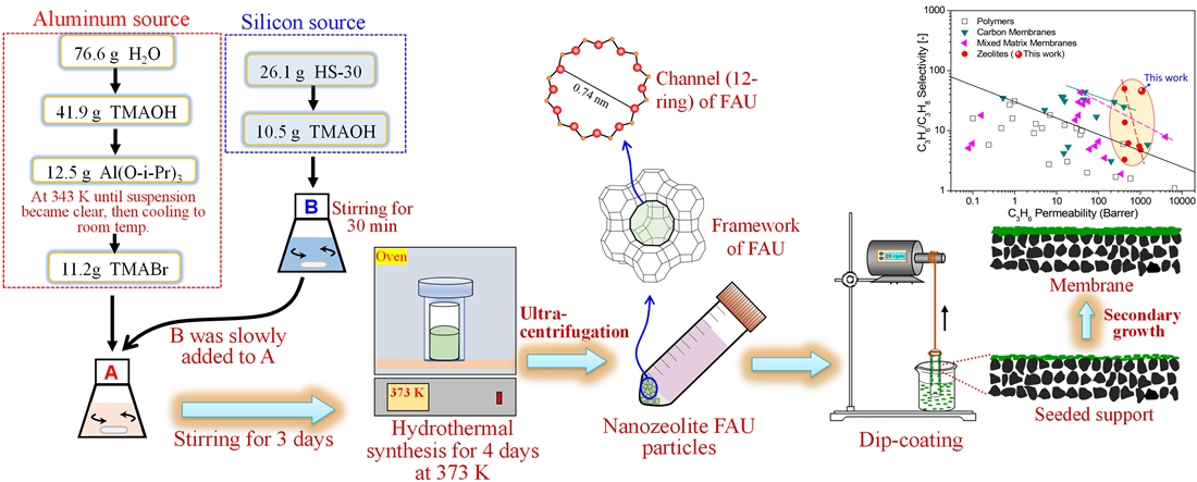
2.2. Synthesis of nano-NaY seeds
2.3. Synthesis of FAU (NaY) membrane
2.4. Characterization and gas permeation
3. Results and discussion
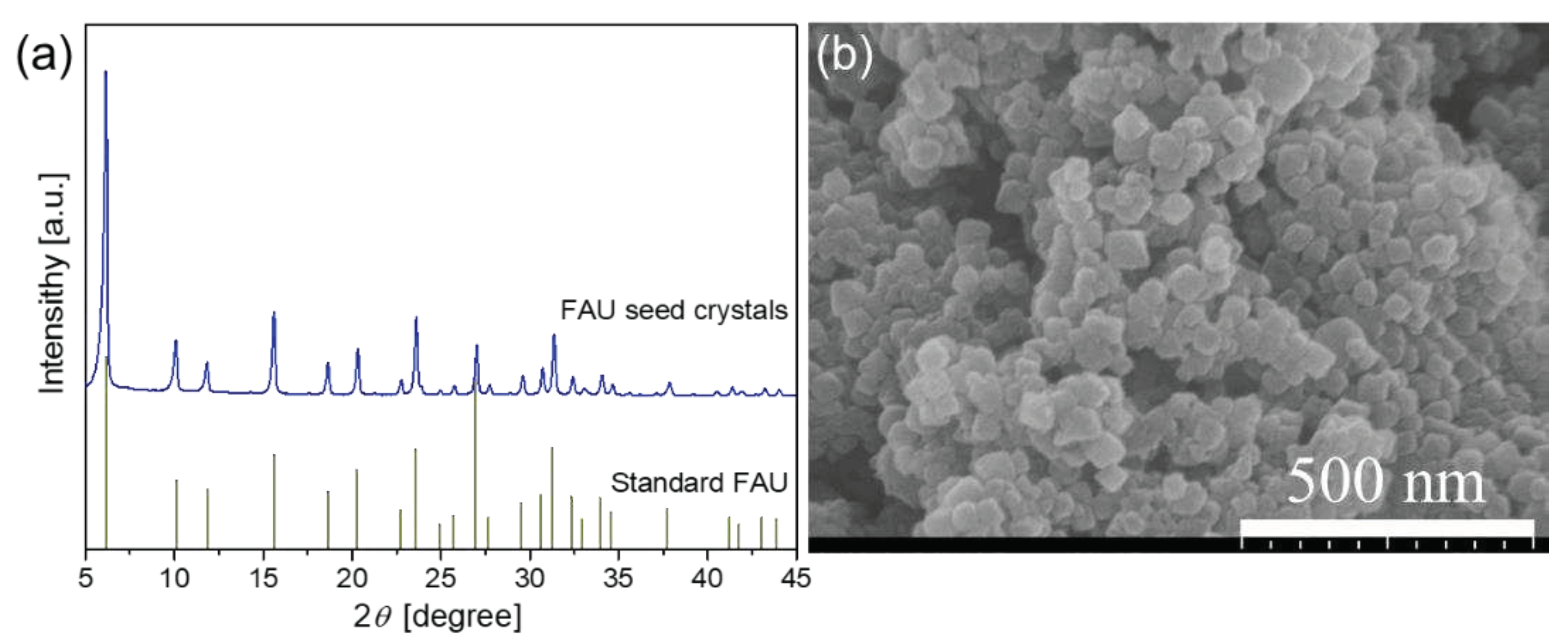
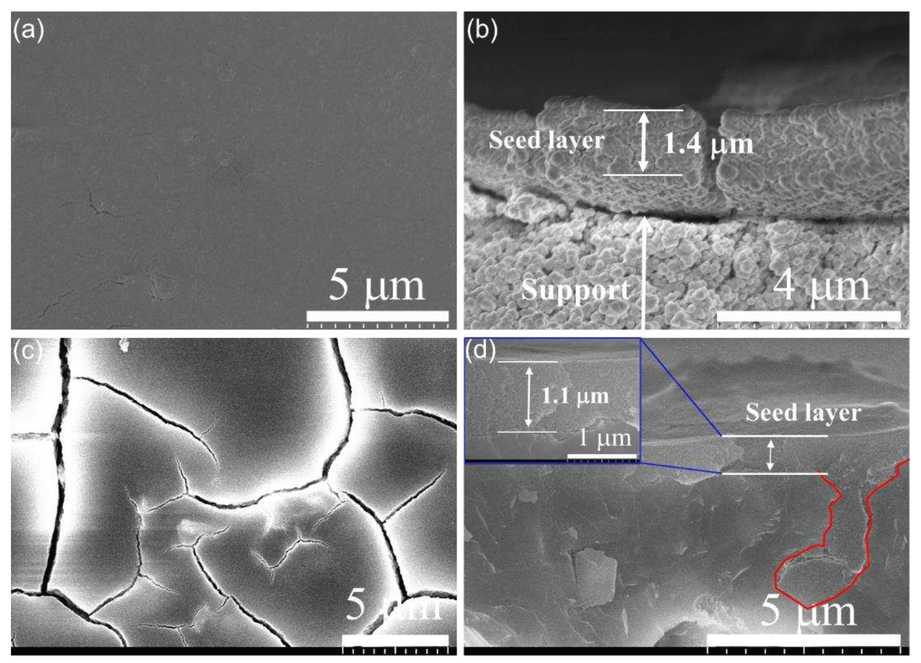
3.1. Characterization of FAU seed and seed layer
3.2. Membrane synthesis under different conditions
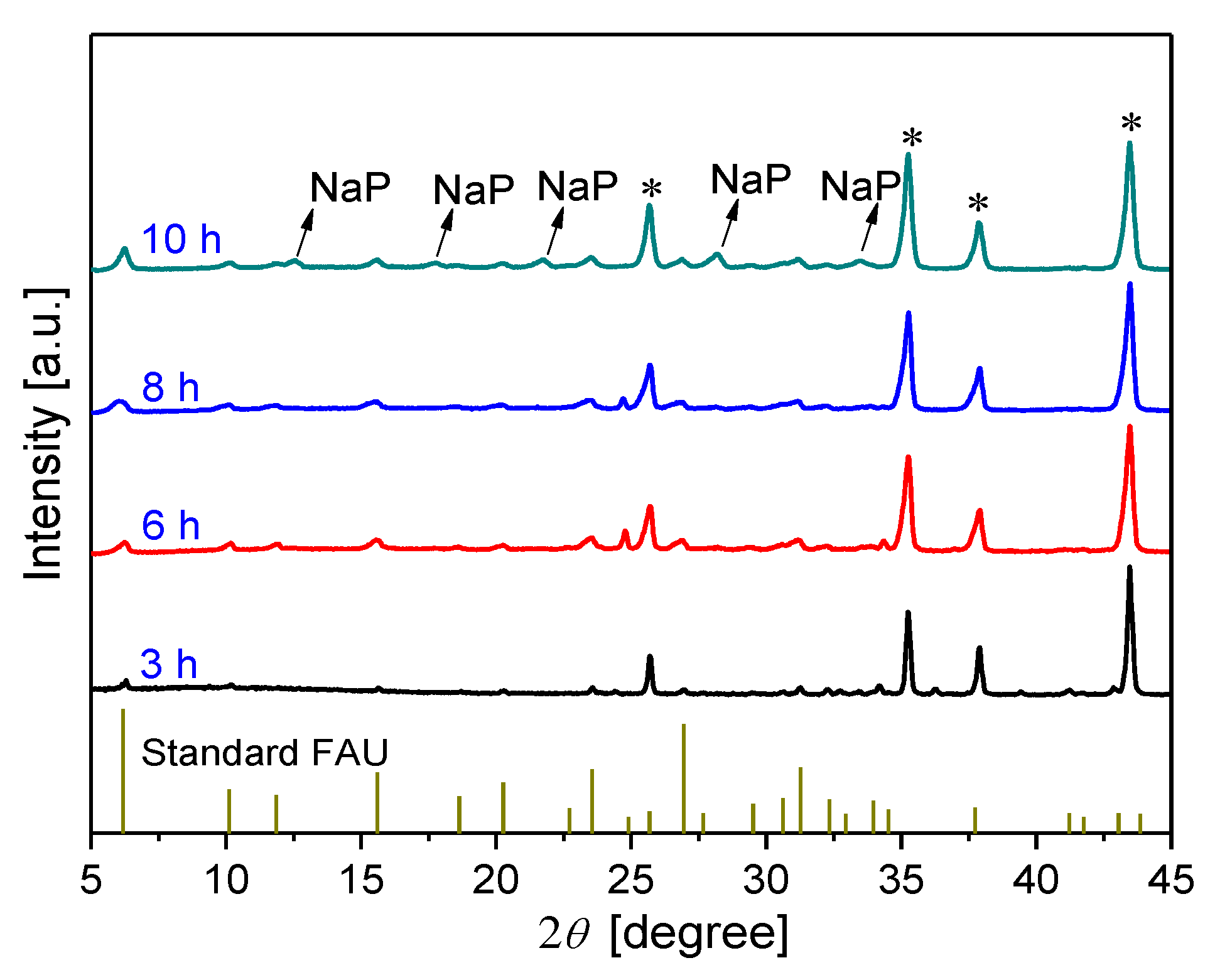
3.2.1. Effect of synthesis time on membrane formation on α-Al2O3 support
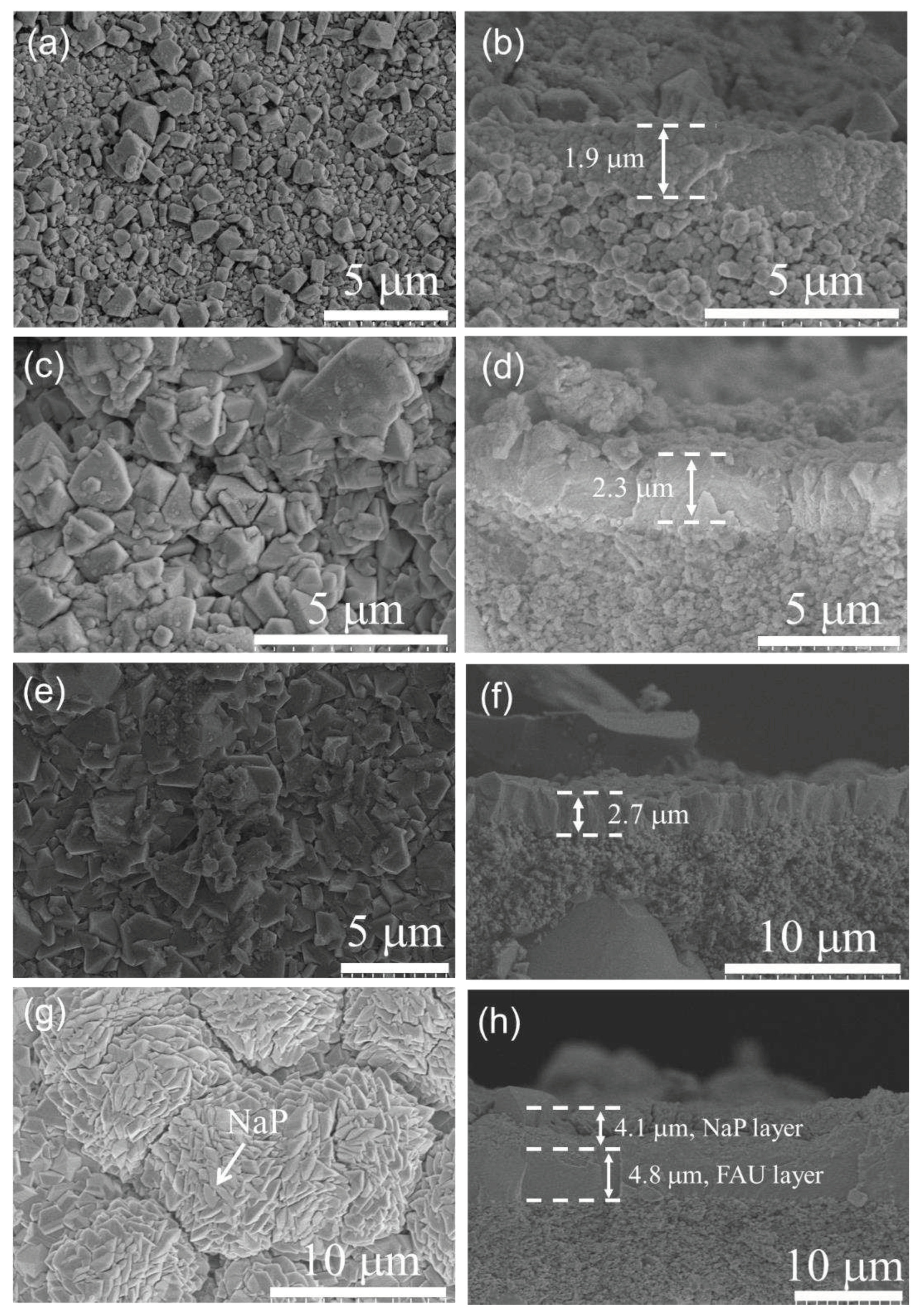
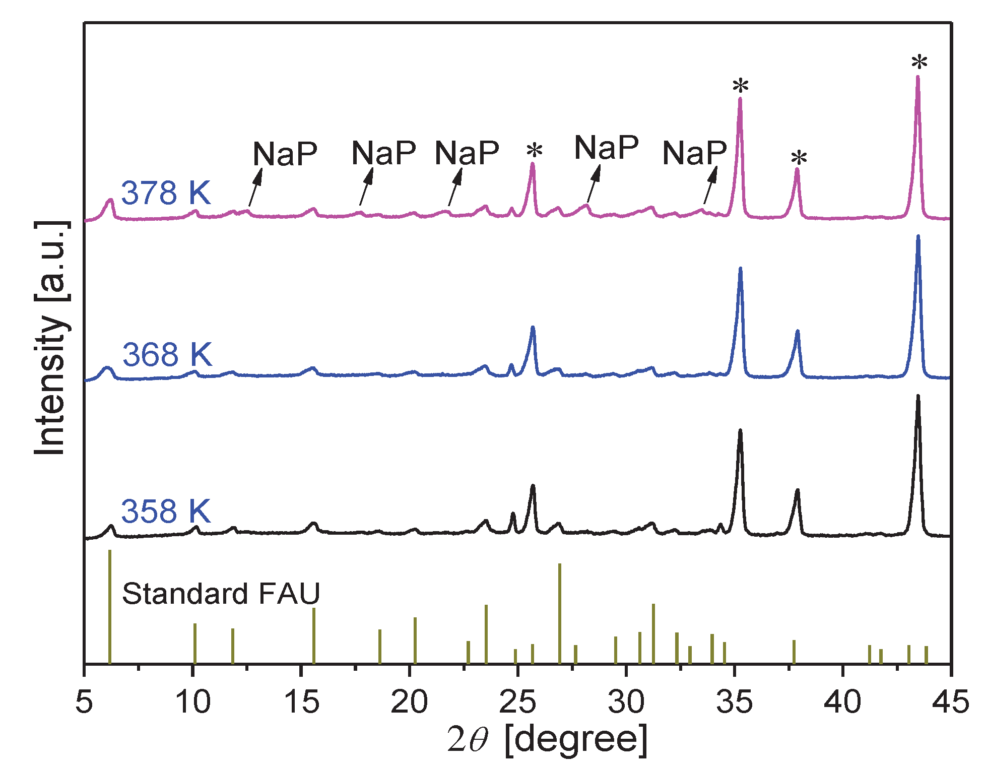
3.2.2. Effect of synthesis temperature on membrane formation on α-Al2O3 support
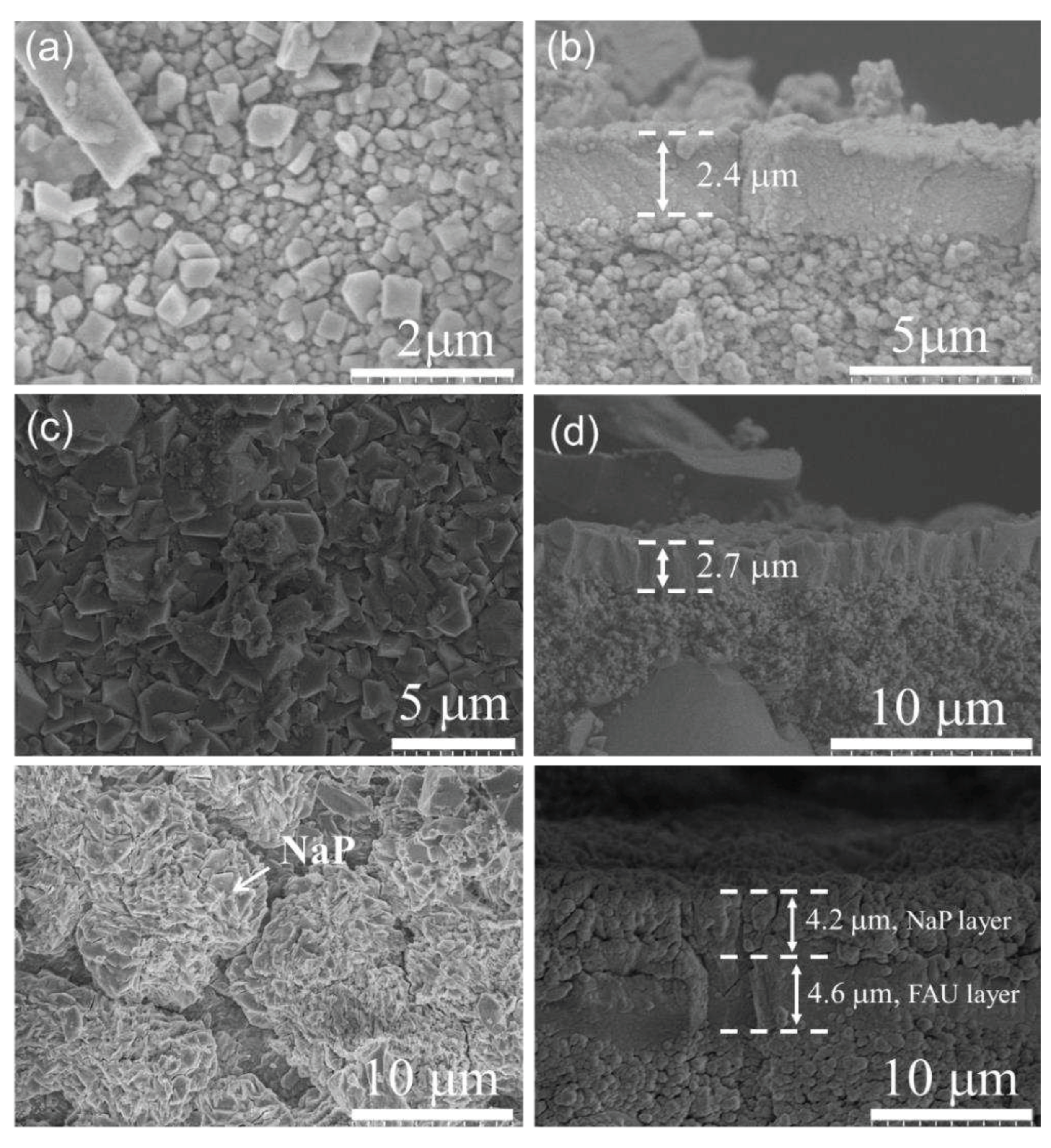
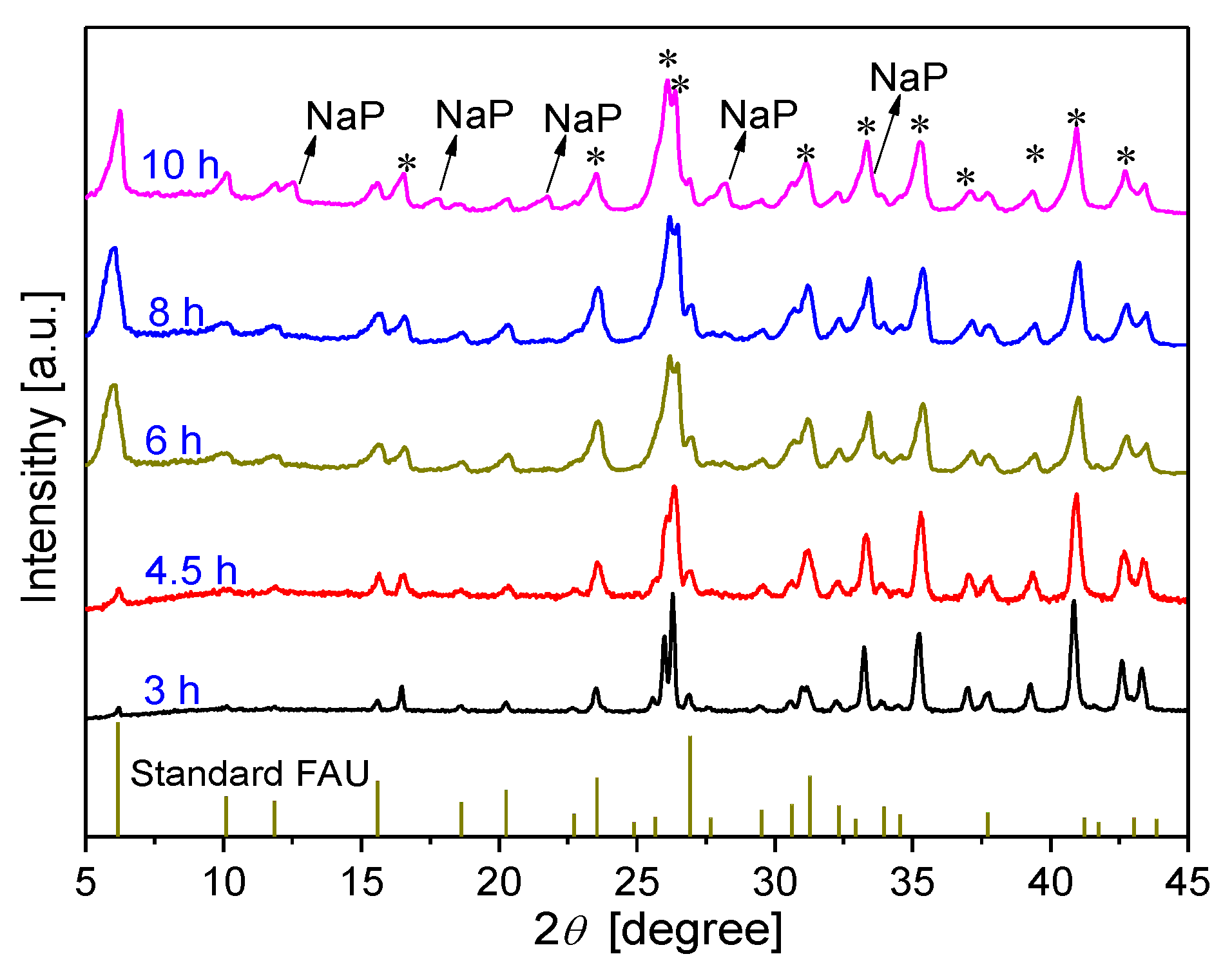
3.2.3. Effect of synthesis time on membrane formation on mullite support
3.3. Gas separation performance
3.3.1. Gas permeation
3.3.2. Membrane reproducibility
3.3.3. Comparing gas separation performance with literature data
4. Conclusions
Supplementary Materials
Author Contributions
Funding
Conflicts of Interest
References
- Sholl, D.S.; Lively, R.P. Seven chemical separations to change the world. Nature 2016, 532, 435–437. [Google Scholar] [CrossRef]
- Shrestha, S.; Dutta, P.K. Modification of a continuous zeolite membrane grown within porous polyethersulfone with Ag (I) cations for enhanced propylene/propane gas separation. Microporous and Mesoporous Materials 2019, 279, 178–185. [Google Scholar] [CrossRef]
- Wang, Q.; Wu, A.; Zhong, S.; Wang, B.; Zhou, R. Highly (h0h)-oriented silicalite-1 membranes for butane isomer separation. Journal of Membrane Science 2017, 540, 50–59. [Google Scholar] [CrossRef]
- Ren, Y.; Liang, X.; Dou, H.; Ye, C.; Guo, Z.; Wang, J.; Pan, Y.; Wu, H.; Guiver, M.D.; Jiang, Z. Membrane-based olefin/paraffin separations. Advanced Science 2020, 7, 2001398. [Google Scholar] [CrossRef] [PubMed]
- Sandru, M.; Sandru, E.M.; Ingram, W.F.; Deng, J.; Stenstad, P.M.; Deng, L.; Spontak, R.J. An integrated materials approach to ultrapermeable and ultraselective CO2 polymer membranes. Science 2022, 376, 90–94. [Google Scholar] [CrossRef]
- Xia, Y.; Cao, H.; Xu, F.; Chen, Y.; Xia, Y.; Zhang, D.; Dai, L.; Qu, K.; Lian, C.; Huang, K. Polymeric membranes with aligned zeolite nanosheets for sustainable energy storage. Nature Sustainability 2022, 5, 1080–1091. [Google Scholar] [CrossRef]
- Wang, N.; Dang, G.; Bai, Z.; Wang, Q.; Liu, B.; Zhou, R.; Xing, W. In Situ Synthesis of Cation-Free Zirconia-Supported Zeolite CHA Membranes for Efficient CO2/CH4 Separation. ACS Applied Materials & Interfaces 2023, 15, 16853–16864. [Google Scholar]
- Huang, W.; He, Z.; Liu, B.; Wang, Q.; Zhong, S.; Zhou, R.; Xing, W. Large surface-to-volume-ratio and ultrahigh selectivity SSZ-13 membranes on 61-channel monoliths for efficient separation of CO2/CH4 mixture. Separation and Purification Technology 2023, 311, 123285. [Google Scholar] [CrossRef]
- Wei, R.; Liu, X.; Zhou, Z.; Chen, C.; Yuan, Y.; Li, Z.; Li, X.; Dong, X.; Lu, D.; Han, Y. Carbon nanotube supported oriented metal organic framework membrane for effective ethylene/ethane separation. Science Advances 2022, 8, eabm6741. [Google Scholar] [CrossRef]
- Basel, N.; Liu, Q.; Fan, L.; Wang, Q.; Xu, N.; Wan, Y.; Dong, Q.; Huang, Z.; Guo, T. Surface charge enhanced synthesis of TpEB-based covalent organic framework (COF) membrane for dye separation with three typical charge properties. Separation and Purification Technology 2022, 303, 122243. [Google Scholar] [CrossRef]
- Liu, Q.; Basel, N.; Li, L.; Xu, N.; Dong, Q.; Fan, L.; Wang, Q.; Ding, A.; Wang, T. Interfacial polymerization of a covalent organic framework layer on titanium dioxide@ graphene oxide/polyacrylonitrile mixed-matrix membranes for high-performance dye separation. Journal of Membrane Science 2022, 647, 120296. [Google Scholar] [CrossRef]
- Tong, H.; Liu, Q.; Xu, N.; Wang, Q.; Fan, L.; Dong, Q.; Ding, A. Efficient Pervaporation for Ethanol Dehydration: Ultrasonic Spraying Preparation of Polyvinyl Alcohol (PVA)/Ti3C2Tx Nanosheet Mixed Matrix Membranes. Membranes 2023, 13, 430. [Google Scholar] [CrossRef] [PubMed]
- Wang, Q.; Zhou, R.; Tsuru, T. Recent Progress in Silicon Carbide-Based Membranes for Gas Separation. Membranes 2022, 12, 1255. [Google Scholar] [CrossRef] [PubMed]
- Wang, Q.; Xu, N.; Liu, Q.; Dong, Q.; Nagasawa, H.; Kanezashi, M.; Zhou, R.; Tsuru, T. Low-temperature cross-linking fabrication of sub-nanoporous SiC-based membranes for application to the pervaporation removal of methanol. Journal of Membrane Science 2022, 662, 121008. [Google Scholar] [CrossRef]
- Yu, X.; Wang, Q.; Nagasawa, H.; Kanezashi, M.; Tsuru, T. SiC mesoporous membranes for sulfuric acid decomposition at high temperatures in the iodine–sulfur process. RSC Advances 2020, 10, 41883–41890. [Google Scholar] [CrossRef]
- Shao, J.; Ge, Q.; Shan, L.; Wang, Z.; Yan, Y. Influences of seeds on the properties of zeolite NaA membranes on alumina hollow fibers. Industrial & engineering chemistry research 2011, 50, 9718–9726. [Google Scholar]
- Zhou, C.; Zhou, J.; Huang, A. Seeding-free synthesis of zeolite FAU membrane for seawater desalination by pervaporation. Microporous and Mesoporous Materials 2016, 234, 377–383. [Google Scholar] [CrossRef]
- Zhou, J.; Zhou, C.; Xu, K.; Caro, J.; Huang, A. Seeding-free synthesis of large tubular zeolite FAU membranes for dewatering of dimethyl carbonate by pervaporation. Microporous and Mesoporous Materials 2020, 292, 109713. [Google Scholar] [CrossRef]
- Zhou, C.; Yuan, C.; Zhu, Y.; Caro, J.; Huang, A. Facile synthesis of zeolite FAU molecular sieve membranes on bio-adhesive polydopamine modified Al2O3 tubes. Journal of membrane science 2015, 494, 174–181. [Google Scholar] [CrossRef]
- Xia, B.; Wang, S.; Li, B.; Cao, Y.; Liu, T.; Gao, P.; Chen, C.; Li, Y. Seeding-free synthesis of FAU-type membrane with dry gel modified α-alumina support. Microporous and Mesoporous Materials 2021, 323, 111219. [Google Scholar] [CrossRef]
- Nazir, L.S.M.; Yeong, Y.F.; Chew, T.L. Methods and synthesis parameters affecting the formation of FAU type zeolite membrane and its separation performance: a review. Journal of Asian Ceramic Societies 2020, 8, 553–571. [Google Scholar] [CrossRef]
- Nazir, L.S.M.; Yeong, Y.F.; Chew, T.L. Study on the effect of seed particle size toward the formation of NaX zeolite membranes via vacuum-assisted seeding technique. Journal of Asian Ceramic Societies 2021, 9, 586–597. [Google Scholar] [CrossRef]
- Gu, X.; Dong, J.; Nenoff, T.M. Synthesis of defect-free FAU-type zeolite membranes and separation for dry and moist CO2/N2 mixtures. Industrial & engineering chemistry research 2005, 44, 937–944. [Google Scholar]
- Holmberg, B.A.; Wang, H.; Norbeck, J.M.; Yan, Y. Controlling size and yield of zeolite Y nanocrystals using tetramethylammonium bromide. Microporous and mesoporous materials 2003, 59, 13–28. [Google Scholar] [CrossRef]
- Wang, Q.; Yu, L.; Nagasawa, H.; Kanezashi, M.; Tsuru, T. High-performance molecular-separation ceramic membranes derived from oxidative cross-linked polytitanocarbosilane. Journal of the American Ceramic Society 2020, 103, 4473–4488. [Google Scholar] [CrossRef]
- Wang, Q.; Kawano, Y.; Yu, L.; Nagasawa, H.; Kanezashi, M.; Tsuru, T. Development of high-performance sub-nanoporous SiC-based membranes derived from polytitanocarbosilane. Journal of Membrane Science 2020, 598, 117688. [Google Scholar] [CrossRef]
- Wang, Q.; Yu, L.; Nagasawa, H.; Kanezashi, M.; Tsuru, T. Tuning the microstructure of polycarbosilane-derived SiC(O) separation membranes via thermal-oxidative cross-linking. Separation and Purification Technology 2020, 248, 117067. [Google Scholar] [CrossRef]
- Wang, Q.; Yokoji, M.; Nagasawa, H.; Yu, L.; Kanezashi, M.; Tsuru, T. Microstructure evolution and enhanced permeation of SiC membranes derived from allylhydridopolycarbosilane. Journal of Membrane Science 2020, 612, 118392. [Google Scholar] [CrossRef]
- Zhou, R.; Zhang, Q.; Shao, J.; Wang, Z.; Chen, X.; Kita, H. Optimization of NaY zeolite membrane preparation for the separation of methanol/methyl methacrylate mixtures. Desalination 2012, 291, 41–47. [Google Scholar] [CrossRef]
- Kumakiri, I.; Yamaguchi, T.; Nakao, S.-i. Preparation of zeolite A and faujasite membranes from a clear solution. Industrial & engineering chemistry research 1999, 38, 4682–4688. [Google Scholar]
- Zhu, F.; Landon, J.; Liu, K. FAU zeolite membranes for dewatering of amine-based post-combustion CO2 capture solutions. AIChE Journal 2020, 66, e17042. [Google Scholar] [CrossRef]
- Okamoto, K.-i.; Kita, H.; Horii, K.; Kondo, K.T. Zeolite NaA membrane: preparation, single-gas permeation, and pervaporation and vapor permeation of water/organic liquid mixtures. Industrial & engineering chemistry research 2001, 40, 163–175. [Google Scholar]
- Lucero, J.M.; Crawford, J.M.; Wolden, C.A.; Carreon, M.A. Tunability of ammonia adsorption over NaP zeolite. Microporous and Mesoporous Materials 2021, 324, 111288. [Google Scholar] [CrossRef]
- Lang, W.-Z.; Ouyang, J.-X.; Guo, Y.-J.; Chu, L.-F. Synthesis of tubular faujasite X-type membranes with mullite supports and their gas permeances for N2/CO2 mixtures. Separation Science and Technology 2011, 46, 1716–1725. [Google Scholar] [CrossRef]
- Wang, B.; Sun, C.; Zhou, R.; Xing, W. A super-permeable and highly-oriented SAPO-34 thin membrane prepared by a green gel-less method using high-aspect-ratio nanosheets for efficient CO2 capture. Chemical Engineering Journal 2022, 442, 136336. [Google Scholar] [CrossRef]
- Zhang, H.; Yang, Y.; Wang, Z. Synthesis of hierarchical LTA zeolite membranes by vapor phase transformation. Journal of Membrane Science 2023, 671, 121391. [Google Scholar] [CrossRef]
- Mundstock, A.; Wang, N.; Friebe, S.; Caro, J. Propane/propene permeation through Na-X membranes: The interplay of separation performance and pre-synthetic support functionalization. Microporous and Mesoporous Materials 2015, 215, 20–28. [Google Scholar] [CrossRef]
- Van Miltenburg, A.; Gascon, J.; Zhu, W.; Kapteijn, F.; Moulijn, J.A. Propylene/propane mixture adsorption on faujasite sorbents. Adsorption 2008, 14, 309–321. [Google Scholar] [CrossRef]
- Carter, J.H.; Bere, T.; Pitchers, J.R.; Hewes, D.G.; Vandegehuchte, B.D.; Kiely, C.J.; Taylor, S.H.; Hutchings, G.J. Direct and oxidative dehydrogenation of propane: from catalyst design to industrial application. Green Chemistry 2021, 23, 9747–9799. [Google Scholar] [CrossRef]

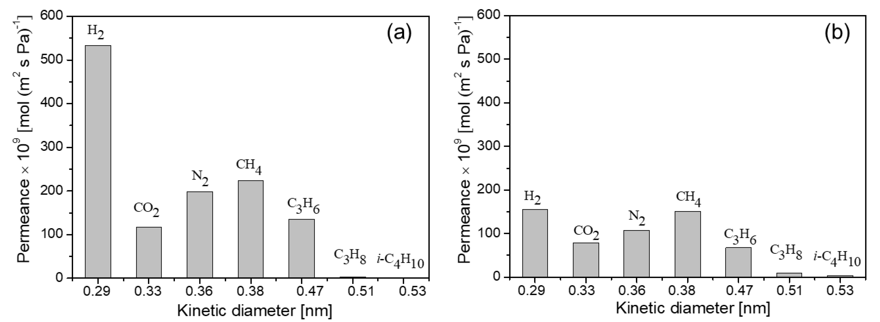

| Membrane | Permeances [×10-7 mol (m2 s Pa)-1] | Selectivity | |||
|---|---|---|---|---|---|
| H2 | C3H6 | H2/C3H8 | H2/i-C4H10 | C3H6/C3H8 | |
| MA-1 | 5.34 | 1.35 | 183 | 315 | 46 |
| MA-2 | 5.11 | 1.22 | 176 | 309 | 42 |
| MA-3 | 4.82 | 1.01 | 188 | 324 | 39 |
| MM-1 | 1.55 | 0.68 | 18 | 46 | 7.9 |
| MM-2 | 1.81 | 0.79 | 15 | 39 | 6.5 |
| MM-3 | 1.50 | 0.59 | 14 | 44 | 5.5 |
| Average for MA | 5.09 ± 0.21 | 1.19 ± 0.14 | 182 ± 5 | 316 ± 6 | 42.3 ± 2.87 |
| Average for MM | 1.62 ± 0.14 | 0.68 ± 0.08 | 16 ± 2 | 43 ± 3 | 6.6 ± 0.98 |
Disclaimer/Publisher’s Note: The statements, opinions and data contained in all publications are solely those of the individual author(s) and contributor(s) and not of MDPI and/or the editor(s). MDPI and/or the editor(s) disclaim responsibility for any injury to people or property resulting from any ideas, methods, instructions or products referred to in the content. |
© 2023 by the authors. Licensee MDPI, Basel, Switzerland. This article is an open access article distributed under the terms and conditions of the Creative Commons Attribution (CC BY) license (http://creativecommons.org/licenses/by/4.0/).


