1. Introduction
In view of the growing demand for polymeric materials with tailored properties, efforts are being made to develop specialized materials that meet different requirements. Among the various approaches, compounding and blending have proven to be the most cost-effective and viable methods for producing tailored polymeric materials [
1]. The quality of the final products obtained through these processes is significantly influenced by the effectiveness of the mixing stage [
2,
3].
During the polymer mixing process, at least two distinct phases are incorporated through the bulk diffusion mechanism, wherein the second phase distributes and disperses within the main polymeric phase [
4]. Explicit models can be employed to investigate the development of morphology or microstructural changes that transpire during the mixing process [
5]. Alternatively, implicit parameters offer another approach to assessing the extent of mixing. These implicit parameters encompass various factors such as residence time [
6,
7], total strain [
6,
7,
8], interfacial area [
6,
9] in passive mixing [
5,
10], the concentration distribution [
11,
12], the ratio of the deformation rate to the vorticity magnitude [
6,
11,
12,
13,
14] and other parameters [
6,
14,
15] such as frame invariant. These parameters enable the evaluation of mixing quality based on the flow field of the single-phase system.
While the single-phase assumption simplifies the numerical assessment of mixing extent, it presents a significant challenge due to moving parts in mixing devices. These moving parts alter the flow domain throughout the mixing process, introducing complexities in the analysis. An approach for such a problem is to define a boundary-fitted mesh and to evaluate the flow field parameters (e.g., the components of the velocity vector and pressure values) as the positions of the internal parts change. This approach has initiated extensive application in evaluating implicit mixing parameters in various mixing devices, including twin-screw extruders [
9,
16,
17,
18,
19] and internal mixers [
12,
20].
Given the intricate geometries of polymer mixers, the mesh generation process in numerical solutions can be particularly time-consuming. To overcome this challenge, researchers have made significant efforts to develop techniques that simplify the mesh generation step in such complex scenarios. For instance, using mesh generation based on boundary-fitted curvilinear coordinates [
21,
22] facilitates grid generation, albeit necessitating adjustments when internal parts' positions change. The moving mesh technique [
23], initially developed for the integral form of governing equations, employs a fixed mesh. Though, in cases where grids are highly deformed or distorted, mesh regeneration becomes necessary. The sliding mesh approach [
24] uses two complementary and fixed grids that slide against each other. Nevertheless, this method requires data interpolation between two separate grids during each time step, rendering it less practical. Additionally, it is not applicable in situations where the moving components of the geometry overlap, such as in intermeshing twin-screw extruders.
Lawal et al. [
25] considered a background mesh covering fluid and solid parts (the rotors in a polymer mixing device). They enforced the velocity of the rotor in the finite element formulation via a penalty term to avoid any mesh regeneration during the mixing process. The fictitious domain method [
26] also uses a static or background mesh covering fluid and solid parts. Within this method, the solid parts are kinematic constraints with known velocity values. Also, some controlling points describe the solid part's shape and velocity. Bertrand et al. [
27] coupled this method with a mesh refinement technique to increase the accuracy of the flow field calculations. Fard et al. [
5] use the fictitious domain method to evaluate the velocity field in an internal mixer. Then Fard and Anderson [
28] employed the extended finite element method (XFEM) to improve the accuracy of the flow field calculations. Mesh refinement and the XFEM introduce new unknowns to the finite element formulation and increase the computation time.
Other methods, such as the cutFEM [
29] and cut cell method [
30,
31,
32], employ a background mesh in a flow field containing a solid. Nevertheless, these method has not yet been used to evaluate a mixer's flow field.
Our goal in this research is to implicitly evaluate the distributive mixing in an internal mixer in two-dimension. We assume a filled chamber with two revolving rotors (solid parts). We employ the finite element method (FEM) [
33,
34] to evaluate the flow field parameters. Also, to increase the accuracy and avoid remeshing during the rotors' rotations, we have used the moving least-squares (MLS) interpolation function, as described in [
35,
36], to enhance the classic finite element shape functions. This method neither introduces new unknowns to the finite element formulation nor requires a local mesh refinement.
The paper encompasses the following content. The second section delves into the governing equations of a two-phase flow problem while providing a concise overview of our solution strategy. The internal mixer's geometry is presented in
Section 3, followed by
Section 4, where we employ the MLS-FEM to compute flow field parameters in the internal mixer's cross-section. We compare these results with those obtained from boundary-fitted or classic FEM. Moving forward,
Section 5 evaluates the mean total strain function as an implicit parameter for distributive mixing. Both MLS-aided and boundary-fitted FEM approaches are employed, showcasing their comparable outcomes. Ultimately,
Section 6 encapsulates our concluding remarks.
2. The governing equations
The creeping motion of an incompressible fluid and its continuity condition can be mathematically represented by Equations (1-a) and (1-b), respectively. These equations employ Einstein's summation notation, utilizing a common index.
Equations (1-a) and (1-b) introduce the coordinates
(
), which represents an arbitrary point (
) in a two-dimensional space. The velocity vector (
), expressed in Cartesian coordinates, is represented by the components
(
). The total stress tensor (
) comprises the scalar values
(
) and is evaluated using equation (1-c). Equations (1-c) and (1-d) involve
and
, which denote the components of the viscous stress (
) and deformation rate (
) tensors, respectively. The parameters
and
represent the hydrostatic pressure and Newtonian viscosity, respectively. The unit tensor (
), denoted by
, has a value of 1 when
, and 0 otherwise (Kronecker delta). The interfacial tension force, represented by
, is described in detail in [
35] through
(
). In our specific problem, the surface tension force is disregarded as the second phase is a solid body, and we assume a no-slip boundary condition at the solid-fluid interface.
In our analysis, we utilize the Galerkin finite element formulation to assess the weighted residual forms of the governing equations, as outlined in equations (2-a) and (2-b).
The equations (2-a) and (2-b) comprise one-dimensional matrices and , which represent bi-linear and bi-quadratic interpolation functions for pressure (P) and velocity (,), respectively. The symbols
and
denote the row and column vectors, correspondingly. We use and to represent the element domain and its boundary, respectively. The vector denotes the unique base vector in the direction, while symbolizes the normal vector to the element boundary.
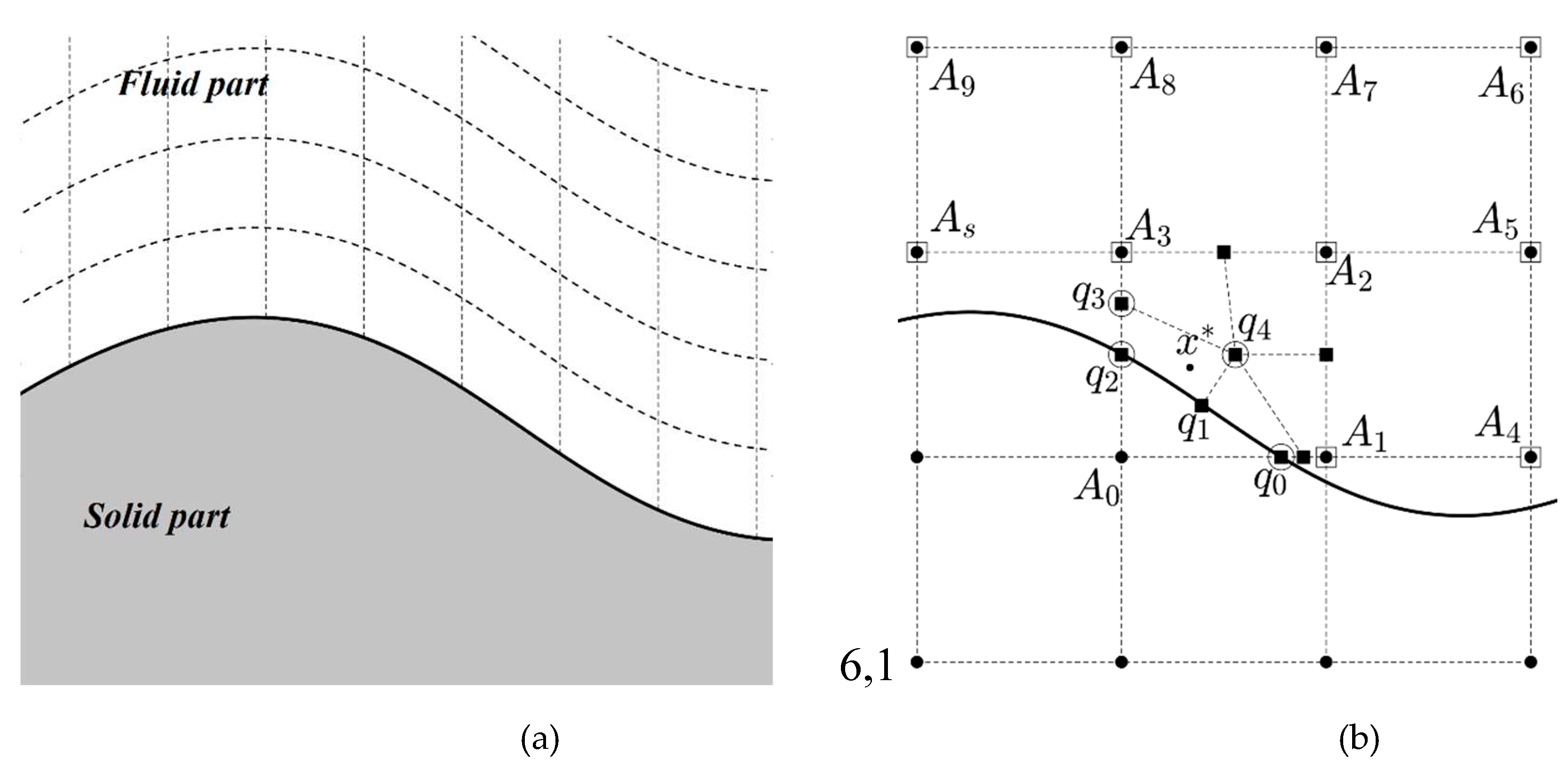
In the classic FEM, the elements comply with the boundary of the fluid domain. Therefore, we name it boundary-fitted FEM, as shown in
Figure 1a. However, to conduct our finite element analysis, as shown in
Figure 1b, we utilize a background mesh encompassing the entire domain, including solid and fluid regions. Therefore, this strategy, known as the moving least-squares aided finite element method (MLS-FEM), eliminates the requirement for remeshing, even when the solid parts are displaced or moved.
By implementing the MLS-FEM, we effectively exclude the solid part by dividing active elements along the solid/fluid boundary. In this context, active elements refer to elements that contain both solid and fluid components.
Figure 1b illustrates a representative active element, denoted as
, and demonstrates its splitting process. Element
consists of two sections, one occupied by fluid. We must divide the fluid-filled portion into rectangular elements to calculate the finite element. As illustrated in
Figure 1b, new elements are created when the splitting process occurs, referred to as sub-elements. These sub-elements consist of nodes, known as quasi-nodes, not all of which are part of the background mesh.
We establish a relationship between the parameter's value (such as the pressure values) at each quasi-node and the surrounding nodal values using the moving least-squares technique to eliminate any extra unknown variables in the finite element formulation. The row-wise vector
in equation (3-a) reads this correlation. It is important to note that our calculations do not consider nodes within the solid region. Equations (3-b) to (3-f) outline the procedure for computing the correlating vector (
).
Equation (3-b) normalizes the coordinates of the neighboring nodes with respect to each quasi-node. The scalar value is in the same order as the element size. Notably, after normalization, the coordinates of the quasi-nodes become . Following this, we construct the coefficient vector and the coefficient matrix using equations (3-c) and (3-d) correspondingly. Next, utilizing the diagonal weighting matrix , with its components introduced in equation (3-e), we proceed to calculate the correlating vector , as outlined in equation (3-f).
Utilizing equation (3-a), we can calculate the pressure value at the quasi-nodes of each sub-element, as described in equation (4-a). Using the classic shape function, equation (4-b) establishes a correlation between the pressure value within a quasi-element (e.g.,
in
Figure 1b) and the values at the corresponding quasi-nodes. By combining equations (4-a) and (4-b), we can introduce the enhanced shape function (
) as expressed in equations (4-c). This enhanced shape function allows a more accurate representation of the pressure distribution within the quasi-element.
In equations (2-a) and (2-b), we substitute the classic bilinear shape function () with an enhanced shape function () for active elements. This implies that we utilize the classic FEM for non-active elements or the elements occupied by the fluid.
The calculation of the enhanced bi-quadratic shape function (
) for velocity values follows a similar approach. However, it incorporates two additional considerations to achieve more accurate results. The first point is the coefficient vector (as described in equation 3-c) replacement with a higher-order polynomial. Secondly, we correlate the velocity of each quasi-node to not only the surrounding nodes but also the quasi-nodes lying on the solid boundary (e.g.,
and
in
Figure 1b). Considering that the quasi-nodes situated on the solid boundary have known velocities, we treat the contribution of these nodes as a source term in the finite element formulation.
3. The geometry of the mixer
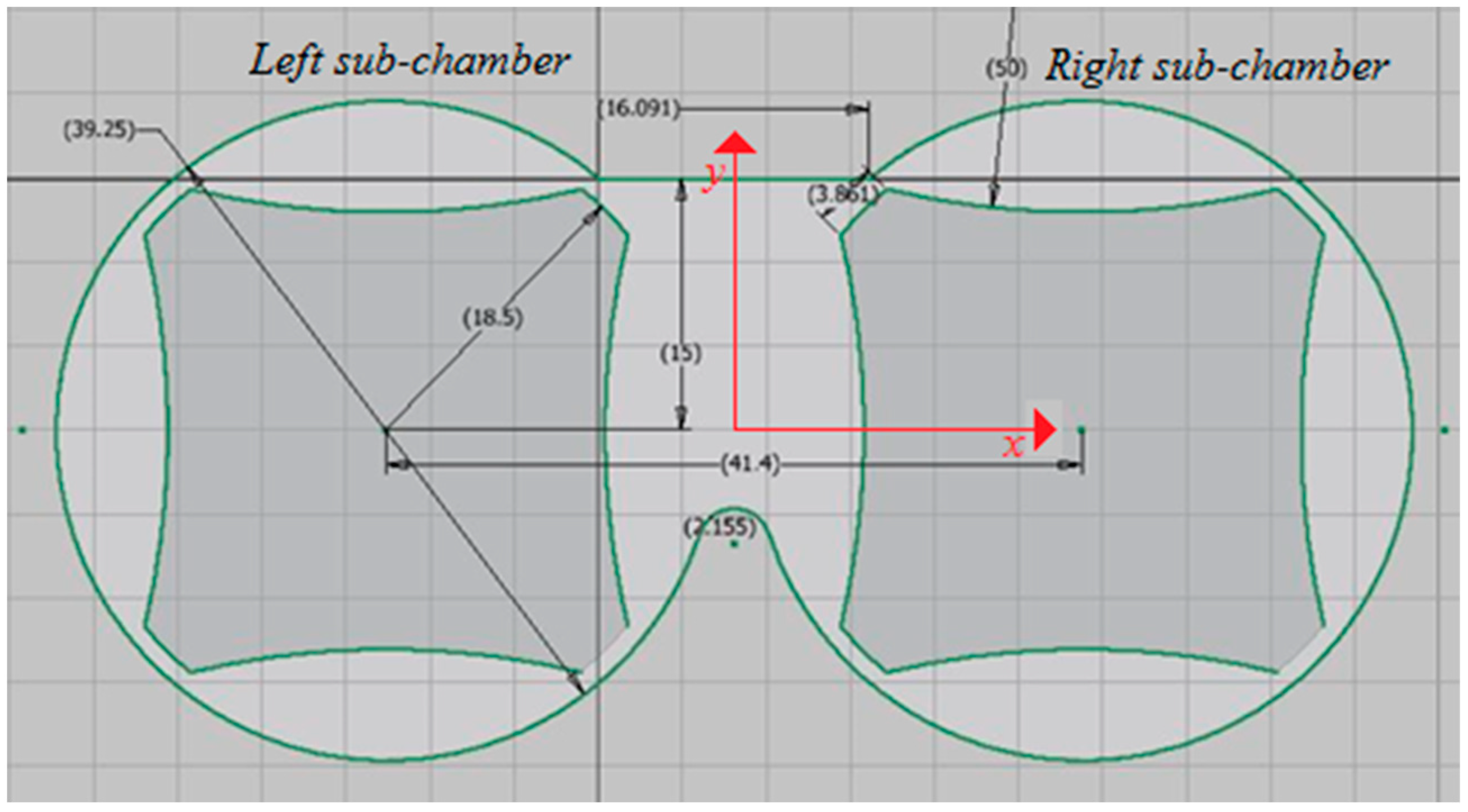
Our study analyzes flow patterns and mixing within a two-dimensional internal mixer, as illustrated in
Figure 2. We name this mixer's left and right parts as the left and right sub-chamber, respectively, as written in
Figure 2. It's worth noting that similar analyses are possible for mixers of varying sizes, geometries, and configurations.
4. Validating the MLS-FEM
The validation process for methods employing a background mesh involves comparing the flow field parameters, such as velocity components and pressure values, with the boundary-fitted mesh FEM [
36,
37]. Here, we have used a similar procedure. On the other hand, we calculate flow field parameters (the velocity component and pressure values) using the MLS-FEM and boundary-fitted mesh FEM and compare the results. If the results of the two methods comply, it confirms that the MLS-FEM approach is a viable alternative that can yield accurate results without mesh regeneration.
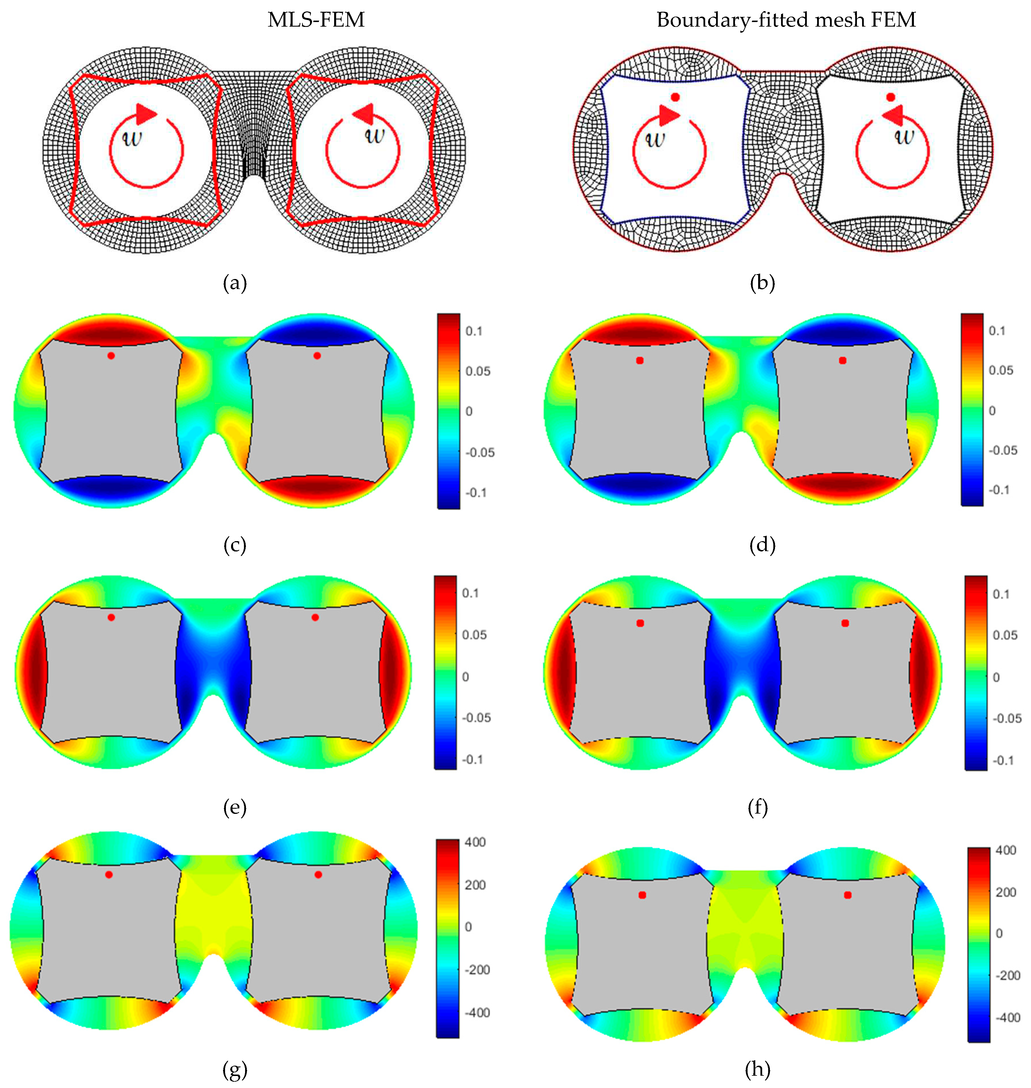
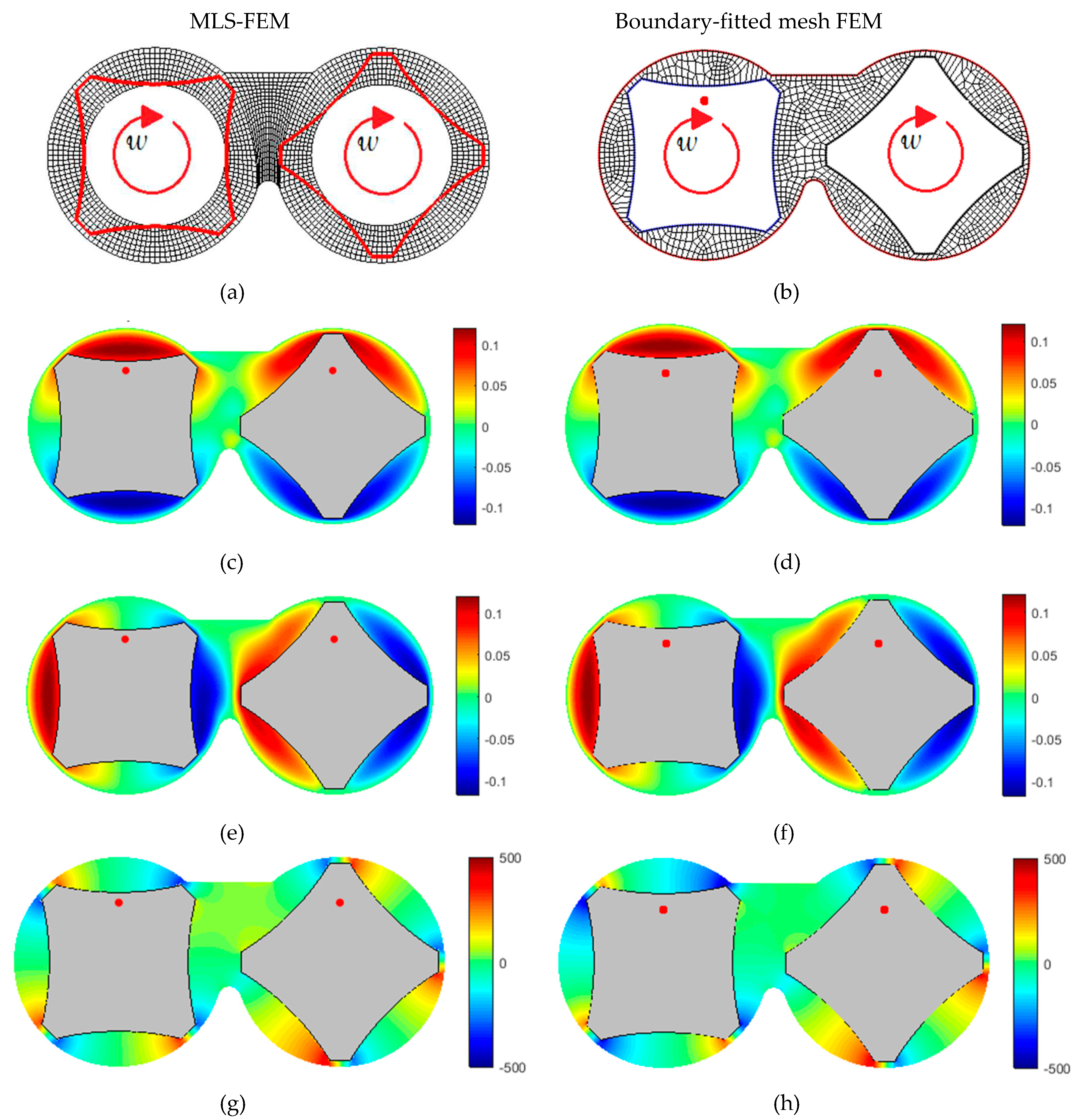
In this section, we have provided two cases for comparison: The first comprises counter-rotating symmetric rotors, and the second includes co-rotating asymmetric rotors. We have conducted several comparisons for various rotor arrangments and rotation directions; however, these data are not presented here for conciseness.
Figures 3a and 4a illustrate the generated mesh for the MLS-FEM (Moving Least Squares Finite Element Method). This mesh consists of a background mesh that covers both the fluid-occupied and solid-occupied regions. Figures 3b and 4b show the grid for the boundary-fitted mesh FEM, which complies with the solid boundary and requires remeshing as the rotors rotate. It is worth noting that in the MLS-FEM, there is no need to generate a new mesh when the positions of the rotors change.
Figure 3c–h and
Figure 4c–h compare the flow field parameters achieved by the MLS-FEM and the boundary-fitted mesh FEM. The similarity between the results of the two methods demonstrates the MLS-FEM’s capability in evaluating the flow field parameters.
5. Distributive mixing:
This section uses MLS-FEM to qualitatively and quantitatively evaluate distributive mixing in the two-dimensional internal mixer and compares it with those of boundary-fitted mesh FEM. For this purpose, we consider the following assumptions:
We arbitrarily choose an asymmetrical arrangement and a counter-rotating operating condition.
We calculate the flow field parameters every degrees of rotation. Therefore, it is necessary to generate mesh after each 5-degree rotation for the boundary-fitted mesh FEM; nevertheless, the M-PVMLS method uses a fixed background mesh.
We use a Newtonian fluid assumption in our calculation; however, extending to generalize Newtonian with shear thinning behavior is not a big challenge.
The rotor speed will not affect the results since our finite element calculations use creeping flow assumption. So, we choose the rotor angular velocity to be . By this assumption, every 5-degree rotation will take seconds.
We introduce four thousand (4000) inert particles to the system and trace them during the first five revolutions of the rotors.
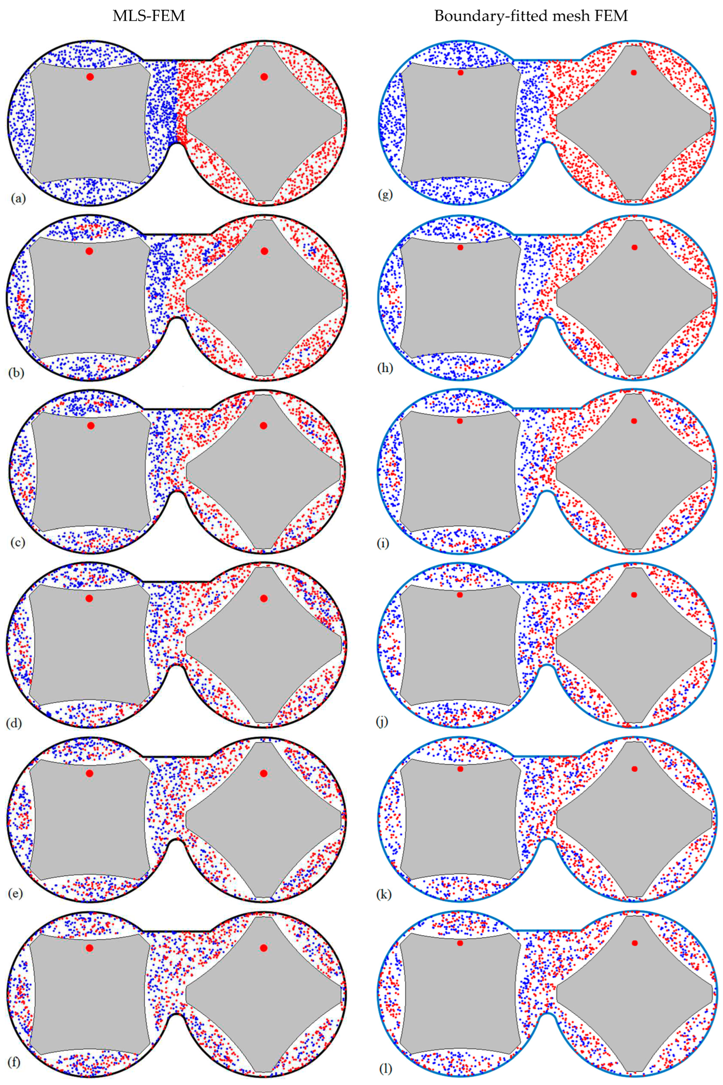
Also, two colors are chosen for each sub-chambers particle to observe the particle exchange between sub-chambers better, as shown in
Figure 5a,g.
For particle tracking, we employ equation (5):
In equation (5), and are the current and the new spatial coordinates of the particle. The parameter is the velocity vector of the particle at , calculated by interpolating among the velocity nodal values inside each element. We perform this calculation for all of the randomly distributed particles () in the mixing chamber. The parameter is the time increment in the particle tracking procedure.
We choose the time increment
so that the particle movement in each step is less than the element length. Disregarding the time constraint can lead the particles beyond the flow domain, interpreted as particle loss [
38]. Therefore the mentioned
is divided into smaller
to maintain the time increment constraint; however, particle loss may be observed, especially for the flow fields with moving parts.
Figure 5a–f show the distribution of the particles from the startup to the fifth revolution, using The MLS-FEM. A comparison of these results with those obtained using the boundary-fitted mesh FEM, as shown in
Figure 5g–l, reveals qualitative similarity in the mixing patterns between the two methods.
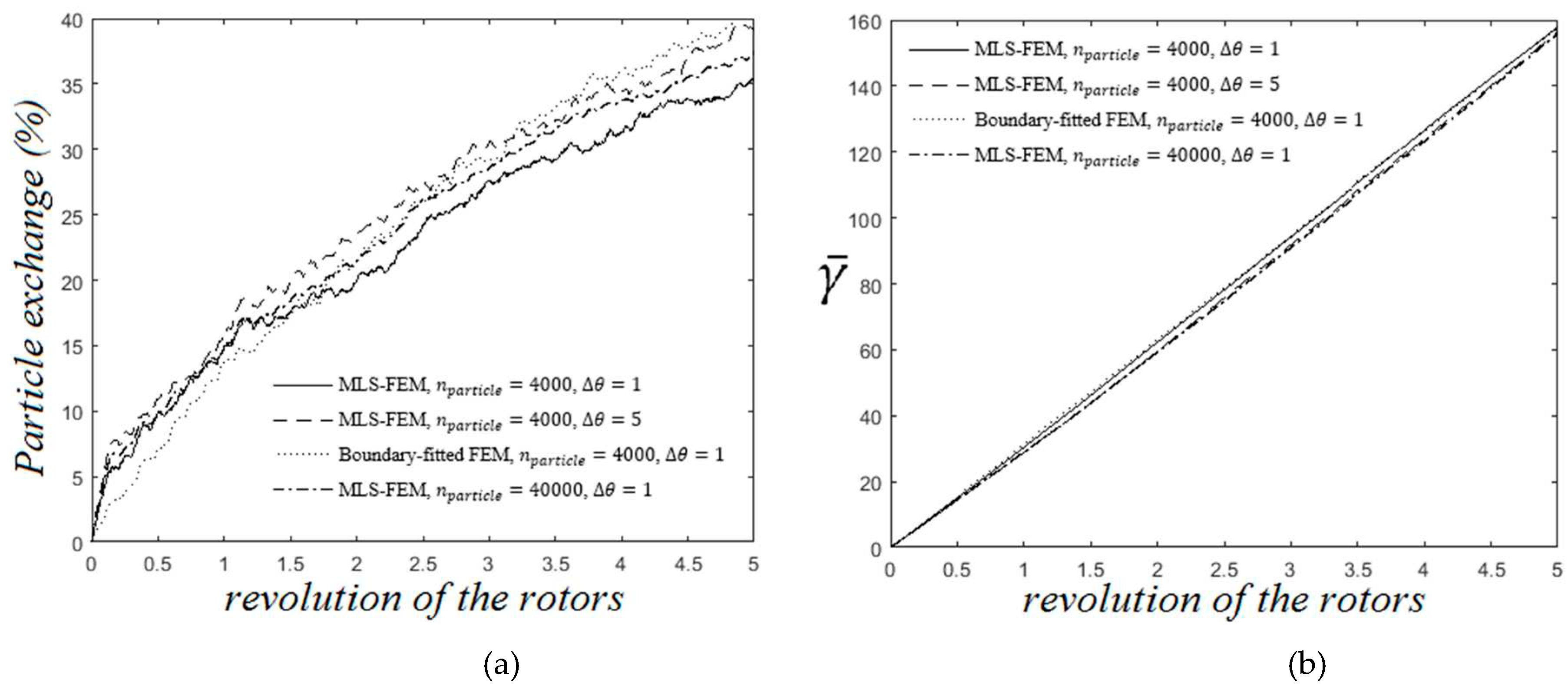
We compare two different mixing parameters to provide a quantitative comparison between the MLS-FEM and the boundary-fitted mesh FEM results. The first parameter is the particle exchange between two sub-chambers. Secondly, the mean average of the total strain (
), as a criterion for distributive mixing, is also calculated based on equations (6-a) and (6-b).
In equation (6-a),
is the total deformation of the
particle after
steps of tracking, as introduced in equation (6-b). The parameter
is the deformation rate of the particle at its current position, calculated by interpolating among the nodal values of the deformation rate magnitude inside each element, as read in equations (7-a) to (7-c).
Figure 6a,b illustrate the particle exchange between two sub-chambers of the mixer and the development of the distributive mixing by an increase of the mean average total strain, respectively. In these figures, we can quantitively observe the agreement between the results of two numerical strategies. Notably, particle exchange is not always an appropriate criterion to evaluate distributive mixing. For example, for a symmetric arrangement of the rotor, its value will be zero because there would be no particle exchange between two sub-chambers.
Figure 6a,b show that increasing the particle number (
) and decreasing the rotation increment (
) do not affect the results; however, reducing
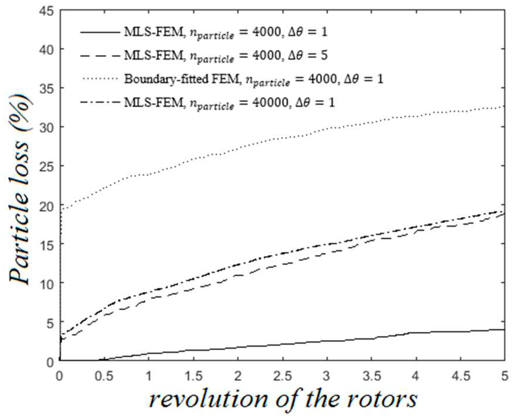
improves the extent of the particle loss, as shown in
Figure 7.
Figure 7 demonstrates the particle loss for two numerical approaches, namely MLS-FEM and boundary-fitted mesh FEM. Ignoring the initial particle loss related to our particle distributing algorithm and not the numerical method, the MLS-FEM and the boundary-fitted mesh FEM exhibit approximately 15 percent particle loss. Decreasing the rotation increment (∆θ) from 5 to 1 significantly reduces the extent of particle loss, as depicted by the solid line in
Figure 7.
Reproducing these results (∆θ=1) using the boundary-fitted mesh FEM would be time-consuming since it requires much more mesh regeneration as the rotation increment decreases. However, we have employed the MLS-FEM, which requires a fixed background mesh and makes it easy to reduce rotation increment. This advantage makes the MLS-FEM more efficient in lowering the computation time and accuracy (e.g., particle loss) than the boundary-fitted FEM.
6. Conclusions
We addressed the regeneration of meshes as a challenge in the numerical analysis of the mixing state of polymer compounds in mixers with moving parts (e.g., rotors). In this context, we presented different approaches using a fixed background mesh instead of multiple boundary-fitted meshes with drawbacks, such as being time-consuming. This point inspired us to introduce MLS-FEM, which uses a fixed background mesh to analyze the flow domain without introducing new degrees of freedom in the finite element formulation.
The moving least-squares aided finite element method (MLS-FEM) uses the MLS technique to enhance the existing shape functions of the FEM. Accordingly, the MLS-FEM considers solid components part of the flow domain and does not need a new mesh as the rotors' position, shape, and orientation change.
To validate our method, we comprehensively compared MLS-FEM's results with that of the boundary-fitted mesh FEM. The qualitative and quantitative similarities between the two approaches revealed our new method's excellent performance.
Author Contributions
Conceptualization and writing, M.M., S.W., G.H.; Software, M.M.; resources and supervision, S.W., G.H. All authors have read and agreed to the published version of the manuscript.
Funding
This research received no external funding.
Conflicts of Interest
The authors declare no conflict of interest.
References
- Manas-Zloczower, "Mixing and compounding of polymers: Theory and practice, chapter 1,," Carl Hanser Verlag GmbH Co KG2012.
- Marini, L.; Georgakis, C. THE EFFECT OF IMPERFECT MIXING ON POLYMER QUALITY IN LOW DENSITY POLYETHYLENE VESSEL REACTORS. Chem. Eng. Commun. 1984, 30, 361–375. [Google Scholar] [CrossRef]
- Buyukgoz, G.G.; Castro, J.N.; Atalla, A.E.; Pentangelo, J.G.; Tripathi, S.; Davé, R.N. Impact of Mixing on Content Uniformity of Thin Polymer Films Containing Drug Micro-Doses. Pharmaceutics 2021, 13, 812. [Google Scholar] [CrossRef] [PubMed]
- I. T: Manas-Zloczower, "Mixing and compounding of polymers, 2012; 3.
- Fard, A.S.; Famili, N.M.; Anderson, P.D. A new adaptation of mapping method to study mixing of multiphase flows in mixers with complex geometries. Comput. Chem. Eng. 2008, 32, 1471–1481. [Google Scholar] [CrossRef]
- Yao, C.-H.; Manas-Zloczower, I. Influence of design on dispersive mixing performance in an axial discharge continuous mixer?LCMAX 40. Polym. Eng. Sci. 1998, 38, 936–946. [Google Scholar] [CrossRef]
- Maheshri, J.C.; Wyman, C.E. Mixing in an intermeshing twin screw extruder chamber: Combined cross and down channel flow. Polym. Eng. Sci. 1980, 20, 601–607. [Google Scholar] [CrossRef]
- van Zuilichem, D.; Kuiper, E.; Stolp, W.; Jager, T. Mixing effects of constituting elements of mixing screws in single and twin screw extruders. Powder Technol. 1999, 106, 147–159. [Google Scholar] [CrossRef]
- Lawal, A.; Kalyon, D.M. Mechanisms of mixing in single and co-rotating twin screw extruders. Polym. Eng. Sci. 1995, 35, 1325–1338. [Google Scholar] [CrossRef]
- Galaktionov, O.S.; Anderson, P.D.; Peters, G.W.; Iii, C.L.T. A global, multi-scale simulation of laminar fluid mixing: the extended mapping method. Int. J. Multiph. Flow 2001, 28, 497–523. [Google Scholar] [CrossRef]
- Connelly, R.K.; Kokini, J.L. Examination of the mixing ability of single and twin screw mixers using 2D finite element method simulation with particle tracking. J. Food Eng. 2007, 79, 956–969. [Google Scholar] [CrossRef]
- The effect of shear thinning and differential viscoelasticity on mixing in a model 2d mixer as determined using fem with particle tracking, Journal of Non-Newtonian Fluid Mechanics 123 (2004), no. 1, 1-17. [CrossRef]
- Rathod, M.L.; Kokini, J.L. Effect of mixer geometry and operating conditions on mixing efficiency of a non-Newtonian fluid in a twin screw mixer. J. Food Eng. 2013, 118, 256–265. [Google Scholar] [CrossRef]
- Wang, W.; Manas-Zloczower, I. Temporal distributions: The basis for the development of mixing indexes for scale-up of polymer processing equipment. Polym. Eng. Sci. 2001, 41, 1068–1077. [Google Scholar] [CrossRef]
- C. H. Yao and I. Manas-Zloczower, Study of mixing efficiency in roll-mills, Polymer Engineering & Science 36 (1996), no. 3, 305-310. [CrossRef]
- Cheng, H.; Manas-Zloczower, I. Study of mixing efficiency in kneading discs of co-rotating twin-screw extruders. Polym. Eng. Sci. 1997, 37, 1082–1090. [Google Scholar] [CrossRef]
- Cheng, H.; Manas-Zloczower, I. Distributive mixing in conveying elements of a ZSK-53 co-rotating twin screw extruder. Polym. Eng. Sci. 1998, 38, 926–935. [Google Scholar] [CrossRef]
- T. Li and I. Manas-Zloczower, A study of distributive mixing in counter-rotating twin screw extruders, International Polymer Processing 10 (1995), no. 4, 314-320. [CrossRef]
- Li, T.; Manas-Zloczower, I. EVALUATION OF DISTRIBUTIVE MIXING EFFICIENCY IN MIXING EQUIPMENT. Chem. Eng. Commun. 1995, 139, 223–231. [Google Scholar] [CrossRef]
- Wong, T.H.; Manas-Zloczower, I. Two-Dimensional Dynamic Study of the Distributive Mixing in an Internal Mixer. Int. Polym. Process. 1994, 9, 3–10. [Google Scholar] [CrossRef]
- Thompson, J.F.; Thames, F.C.; Mastin, C. Automatic numerical generation of body-fitted curvilinear coordinate system for field containing any number of arbitrary two-dimensional bodies. J. Comput. Phys. 1974, 15, 299–319. [Google Scholar] [CrossRef]
- J. F. Thompson, Z. U. J. F. Thompson, Z. U. Warsi and C. W. Mastin, Numerical grid generation: Foundations and applications, Elsevier North-Holland, Inc.1985.
- Demirdžić, I.; Perić, M. Finite volume method for prediction of fluid flow in arbitrarily shaped domains with moving boundaries. Int. J. Numer. Methods Fluids 1990, 10, 771–790. [Google Scholar] [CrossRef]
- C.-Y. Perng and J. Y. Murthy, Sliding-mesh technique for simulation of flow in mixing tanks, The ASME Winter Conference, New Orleans, LA, USA, 11/28-12/03/931993, pp. 1-9.
- A. Lawal, D. M. A. Lawal, D. M. Kalyon and Z. Ji, Computational study of chaotic mixing in co-rotating two-tipped kneading paddles: Two-dimensional approach, Polymer Engineering & Science 33 (1993), no. 3, 140-148. [CrossRef]
- F. Bertrand, P.
- Bertrand, F.; Thibault, F.; Delamare, L.; Tanguy, P. Adaptive finite element simulations of fluid flow in twin-screw extruders. Comput. Chem. Eng. 2003, 27, 491–500. [Google Scholar] [CrossRef]
- Fard, A.S.; Anderson, P.D. Simulation of distributive mixing inside mixing elements of co-rotating twin-screw extruders. Comput. Fluids 2013, 87, 79–91. [Google Scholar] [CrossRef]
- B. Schott, "Stabilized cut finite element methods for complex interface coupled flow problems," Technische Universität München2017.
- Tucker, P.; Pan, Z. A Cartesian cut cell method for incompressible viscous flow. Appl. Math. Model. 2000, 24, 591–606. [Google Scholar] [CrossRef]
- Yang, G.; Causon, D.M.; Ingram, D.M.; Saunders, R.; Battent, P. A cartesian cut cell method for compressible flows Part A: static body problems. Aeronaut. J. 1997, 101, 47–56. [Google Scholar] [CrossRef]
- A cartesian cut cell method for compressible flows part b: Moving body problems, The Aeronautical Journal 101 (1997), no. 1002, 57-65. [CrossRef]
- Mostafaiyan, M.; Wiessner, S.; Heinrich, G. The study of the distributive mixing in converging channels: Numerical method and analytical approach. Polym. Eng. Sci. 2015, 55, 2285–2292. [Google Scholar] [CrossRef]
- Mostafaiyan, M.; Wiessner, S.; Heinrich, G. Study of Dispersive and Distributive Mixing in a Converging Pipe. Int. Polym. Process. 2016, 31, 327–335. [Google Scholar] [CrossRef]
- Mostafaiyan, M.; Wießner, S.; Heinrich, G.; Hosseini, M.S.; Domurath, J.; Khonakdar, H.A. Application of local least squares finite element method (LLSFEM) in the interface capturing of two-phase flow systems. Comput. Fluids 2018, 174, 110–121. [Google Scholar] [CrossRef]
- Choi, Y.J.; Hulsen, M.A.; Meijer, H.E. Simulation of the flow of a viscoelastic fluid around a stationary cylinder using an extended finite element method. Comput. Fluids 2012, 57, 183–194. [Google Scholar] [CrossRef]
- Fard, A.S.; Hulsen, M.A.; Meijer, H.E.H.; Famili, N.M.H.; Anderson, P.D. Adaptive non-conformal mesh refinement and extended finite element method for viscous flow inside complex moving geometries. Int. J. Numer. Methods Fluids 2011, 68, 1031–1052. [Google Scholar] [CrossRef]
- Fard, A.S.; Hulsen, M.A.; Meijer, H.E.H.; Famili, N.M.H.; Anderson, P.D. Tools to Simulate Distributive Mixing in Twin-Screw Extruders. Macromol. Theory Simulations 2012, 21, 217–240. [Google Scholar] [CrossRef]
|
Disclaimer/Publisher’s Note: The statements, opinions and data contained in all publications are solely those of the individual author(s) and contributor(s) and not of MDPI and/or the editor(s). MDPI and/or the editor(s) disclaim responsibility for any injury to people or property resulting from any ideas, methods, instructions or products referred to in the content. |
© 2023 by the authors. Licensee MDPI, Basel, Switzerland. This article is an open access article distributed under the terms and conditions of the Creative Commons Attribution (CC BY) license (https://creativecommons.org/licenses/by/4.0/).
