Submitted:
18 October 2023
Posted:
19 October 2023
You are already at the latest version
Abstract
Keywords:
1. Introduction
- A method of control has been created to enhance the real-time control of BLDC motors for electric vehicles.
- Implementing a BLDC motor speed control for electric automobile applications and explaining electric vehicle technology.
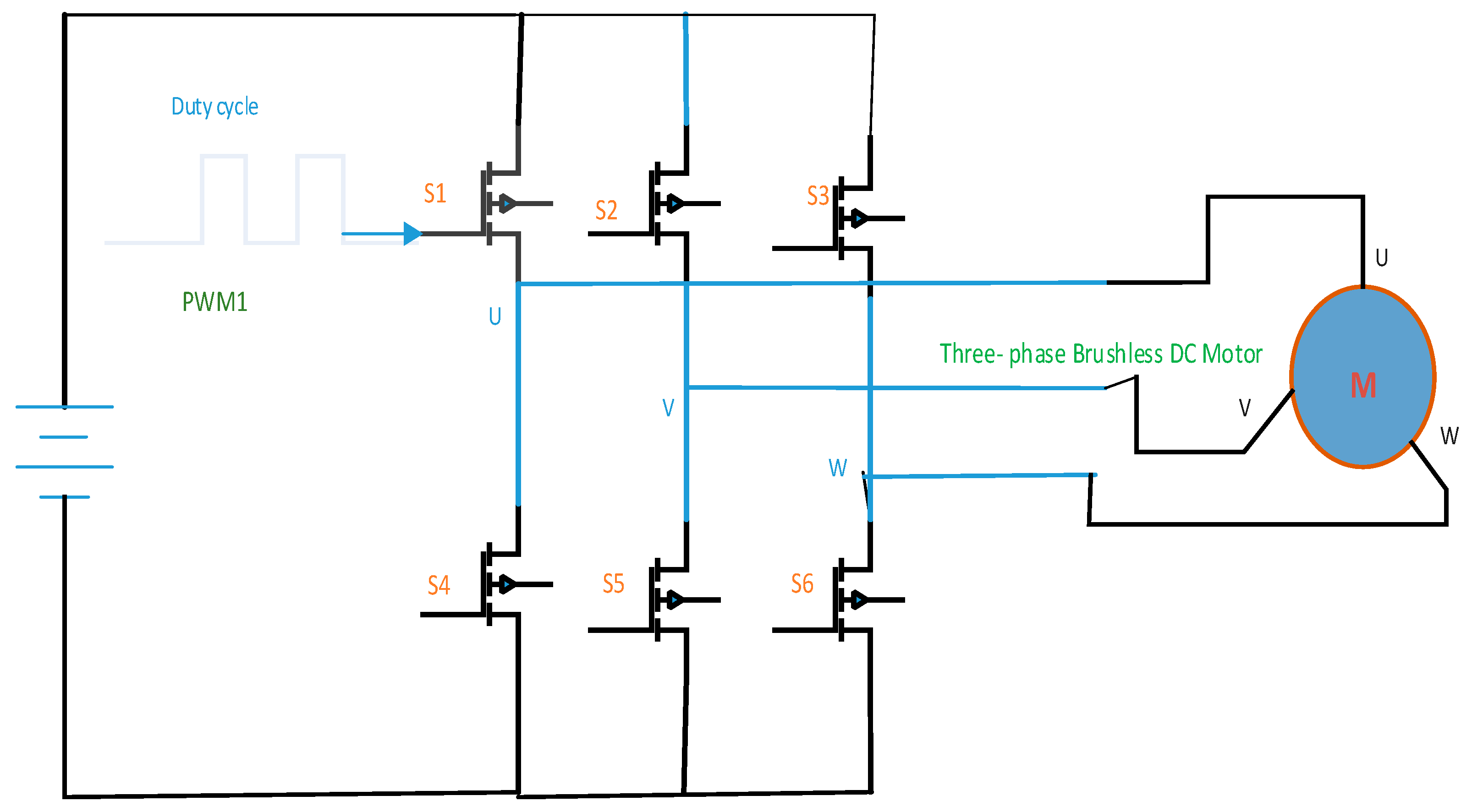
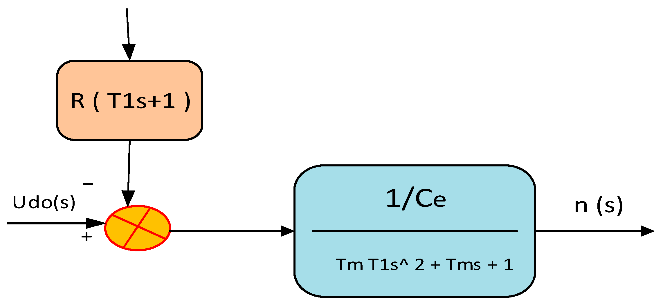
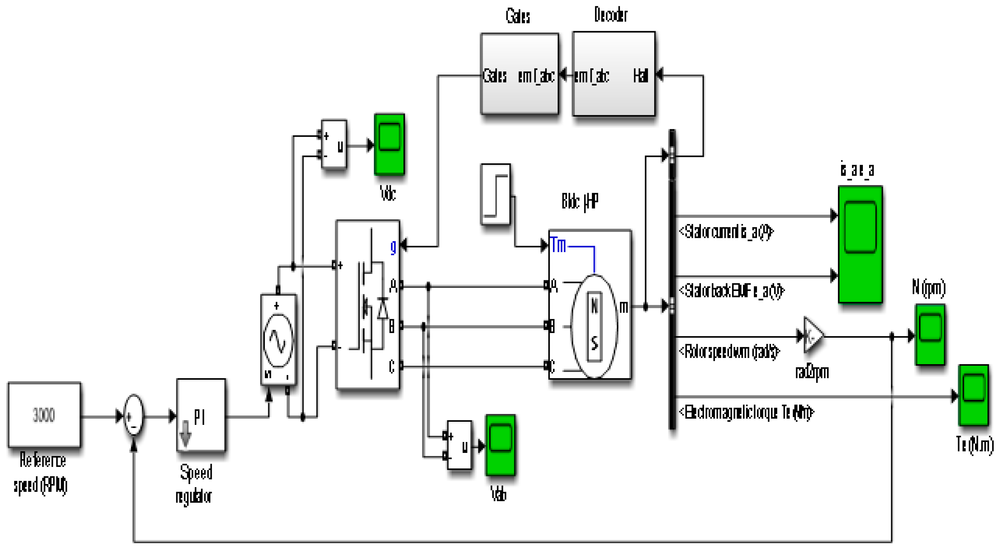
- A model was created for the 120-degree mode using electrical and mechanical equations using MATLAB/Simulink.
- Investigate three scenarios for the possibility of controlling BLDC motors by using constant and dynamic speed and torque.
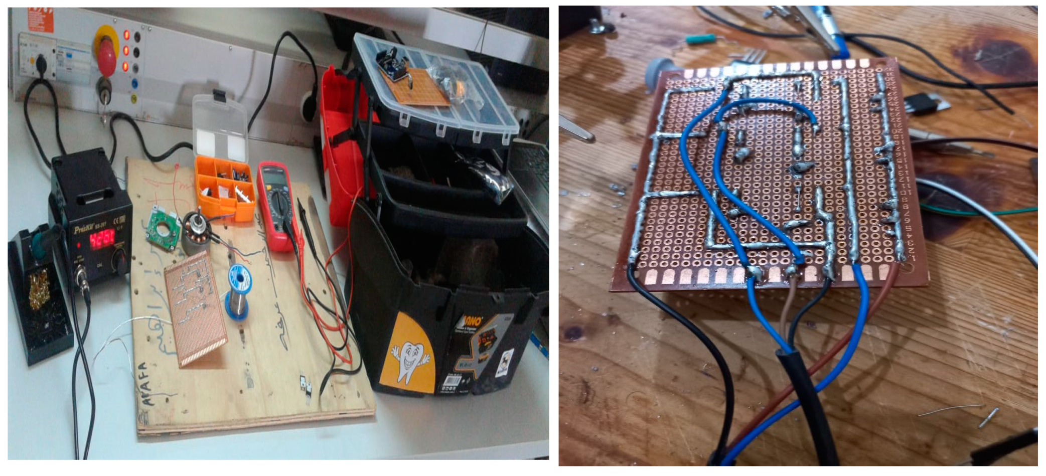
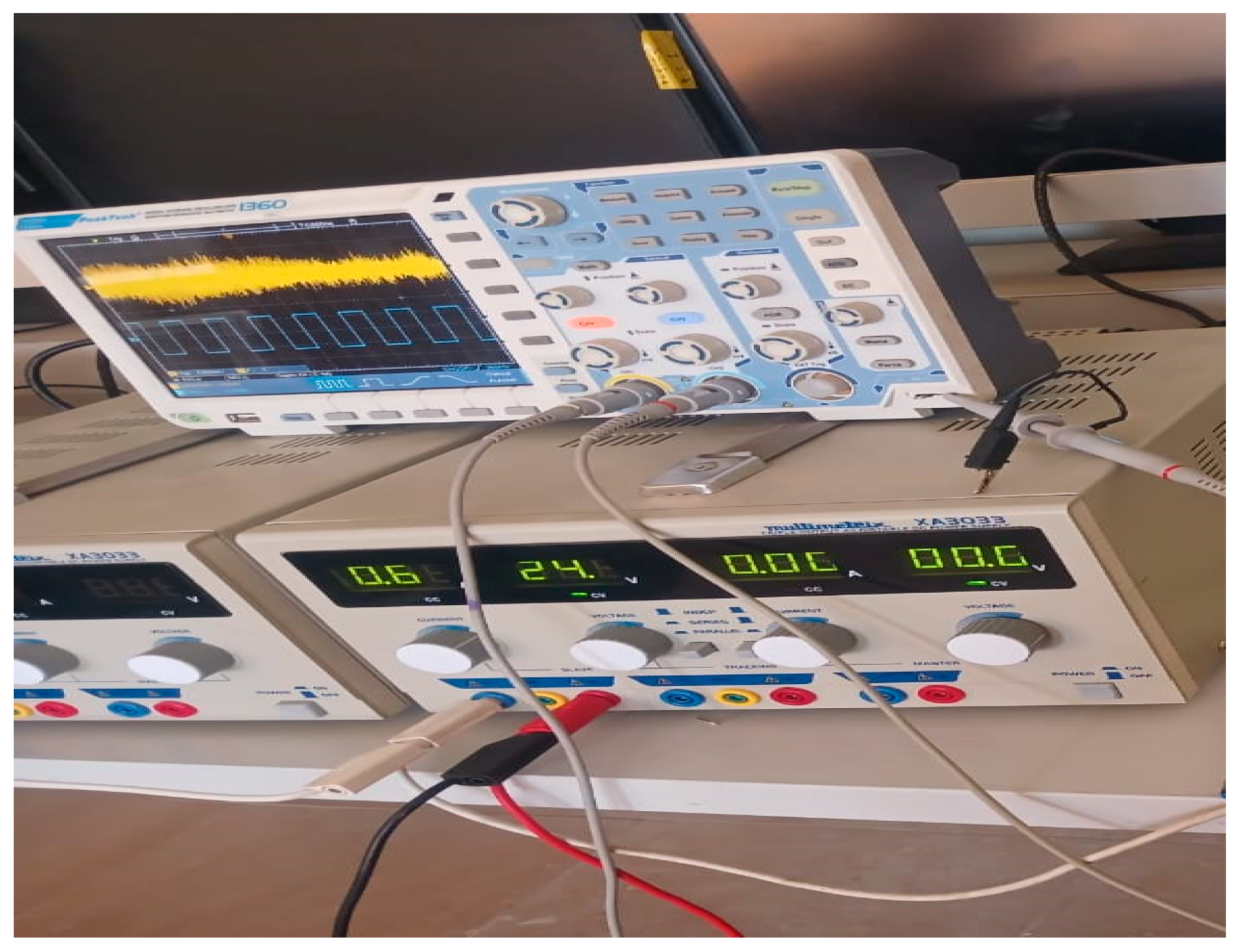
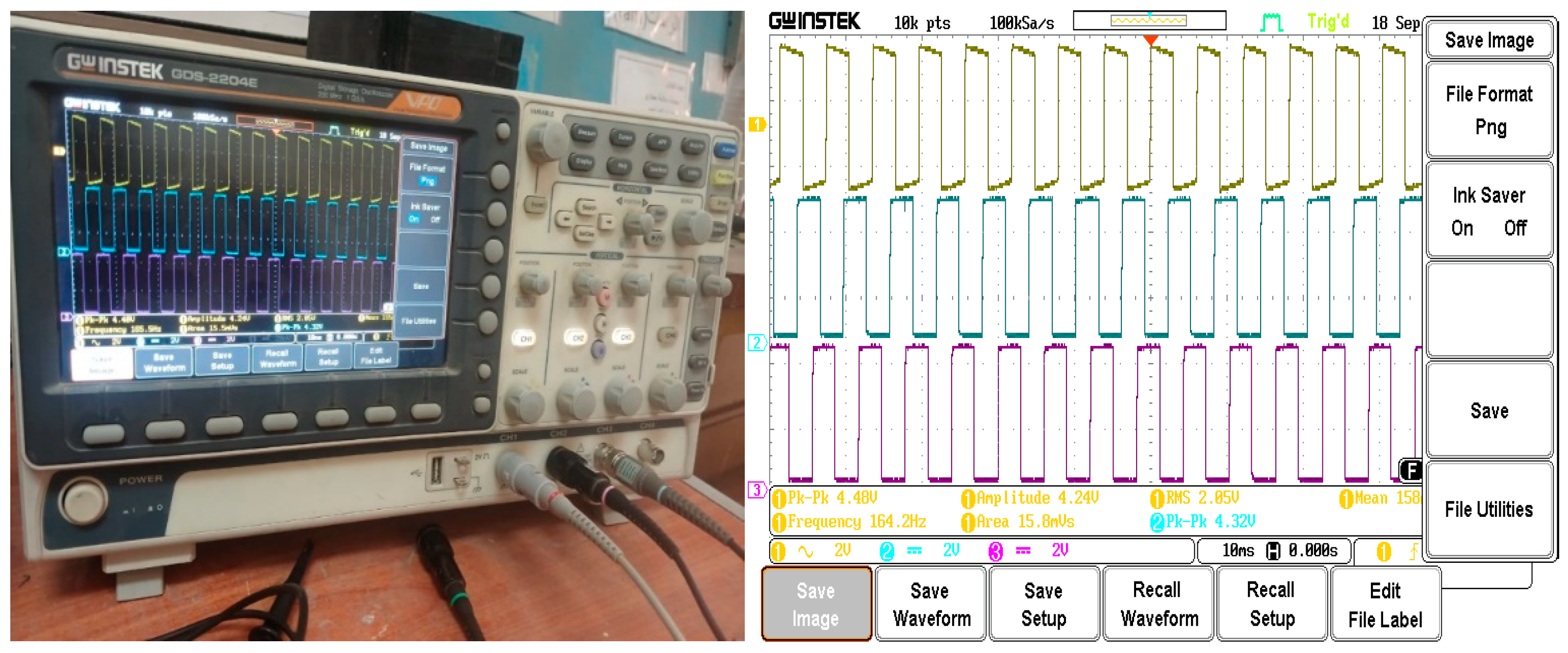
- The proposed control techniques are studied and tested on the MATLAB software platform and experimental lab.
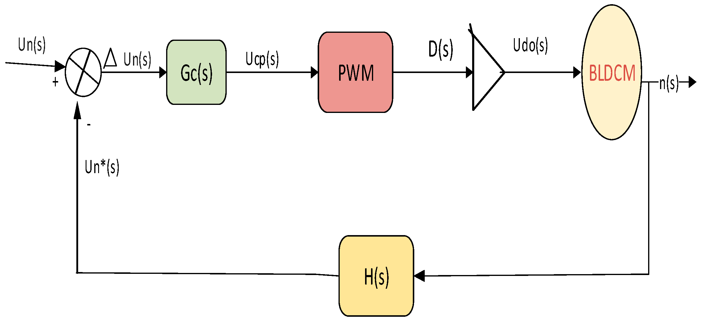
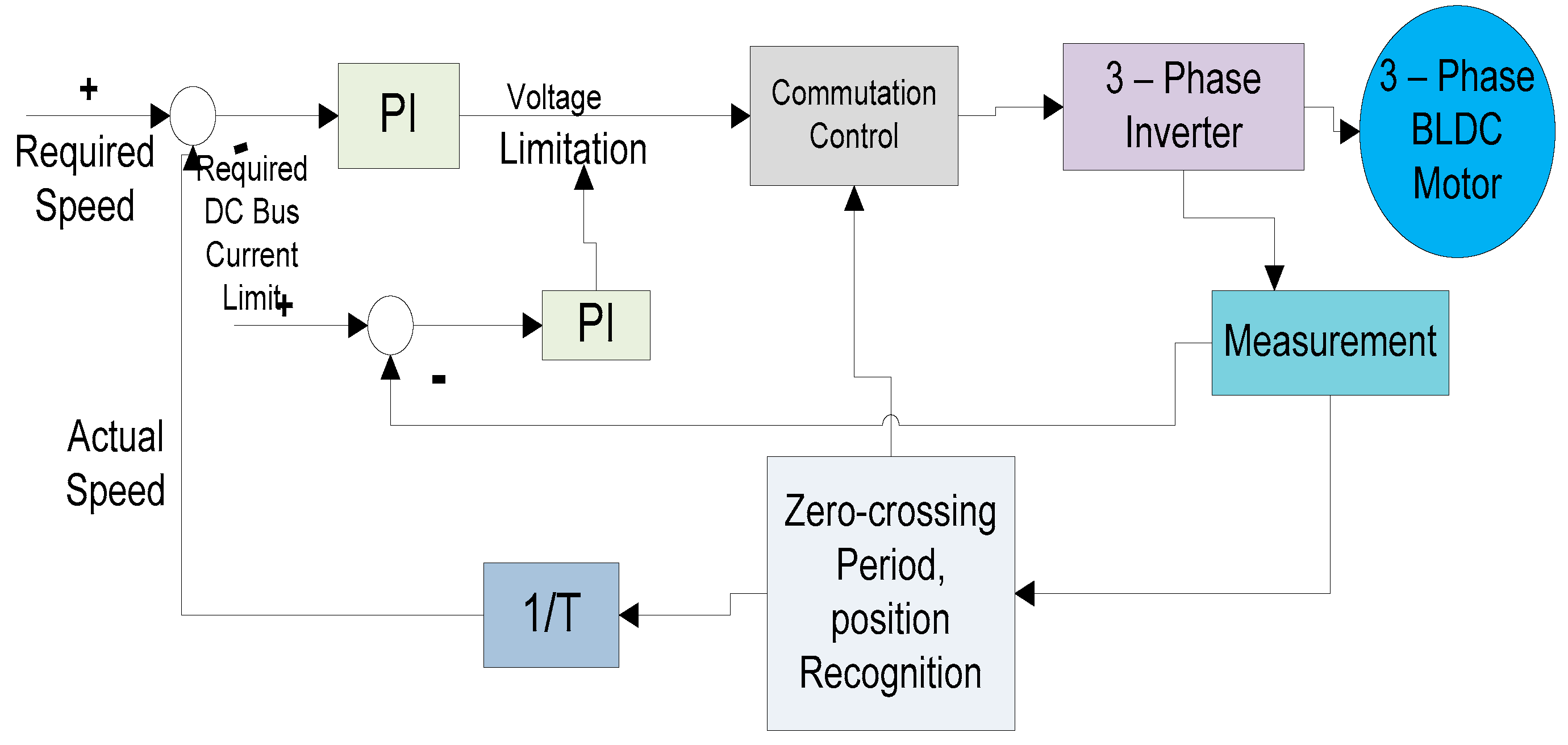
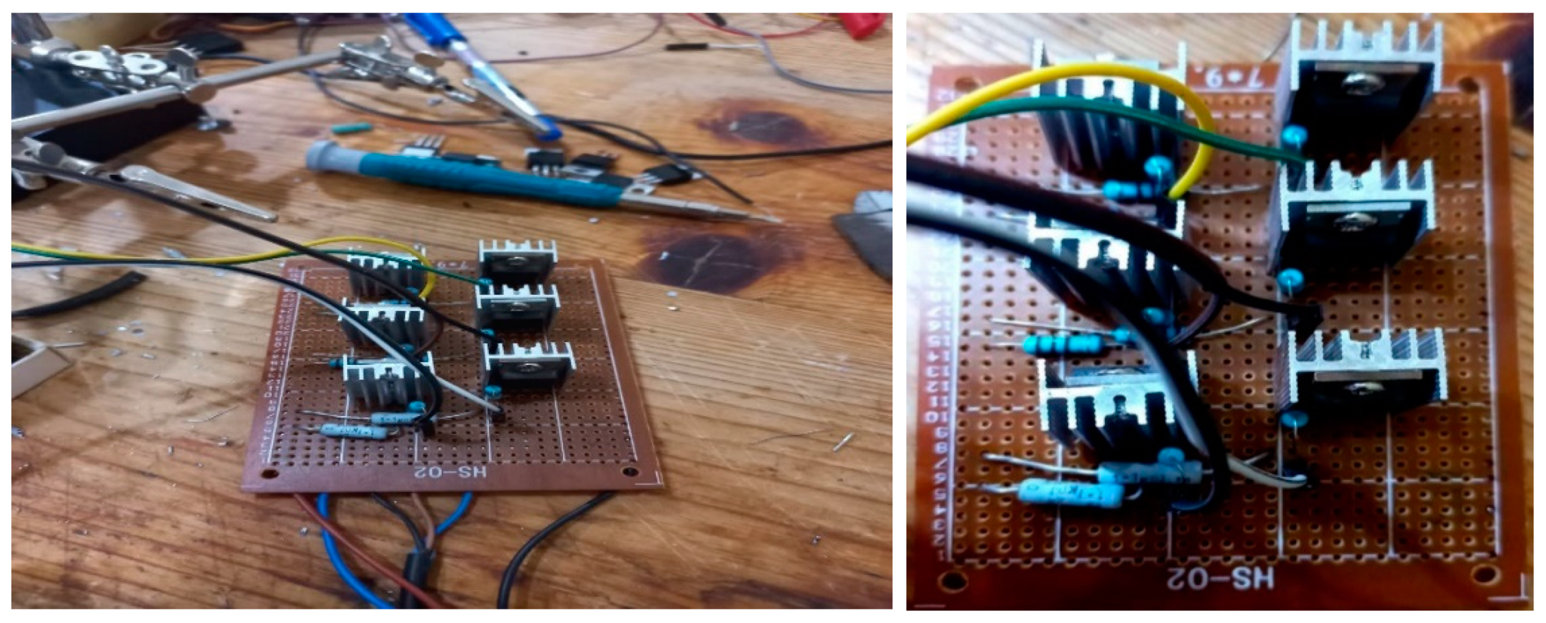
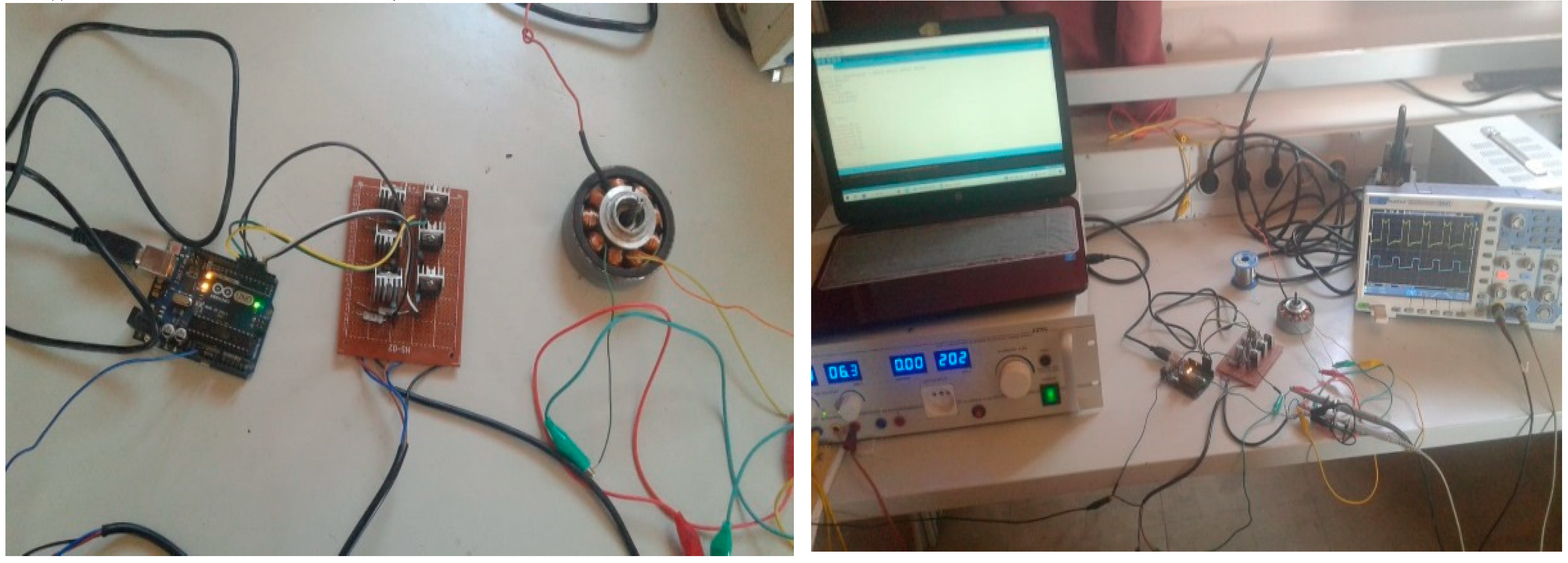
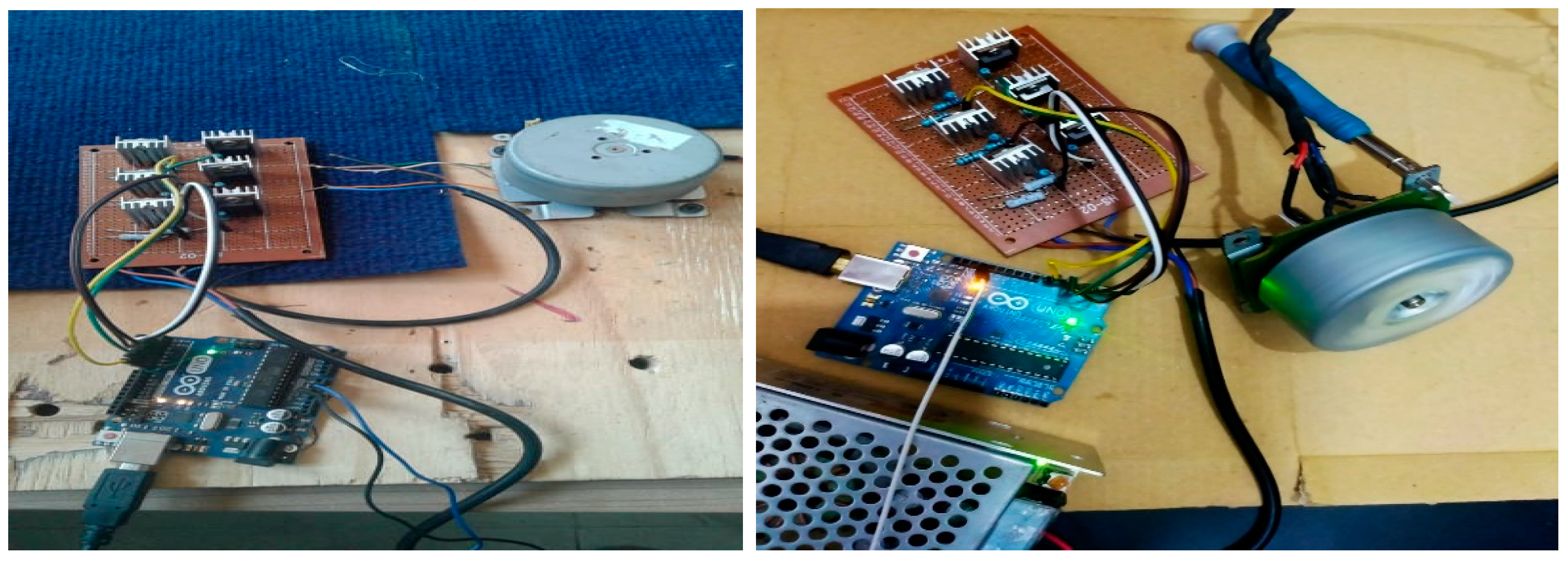
- A test bench was created to thoroughly improve power electronics and real-time control of the BLDC motor, especially with regard to PWM approaches, signal generation, and speed control in both theory and practice.
- Implementation of the control schemes uses both soft switching and hard switching PWM approaches.
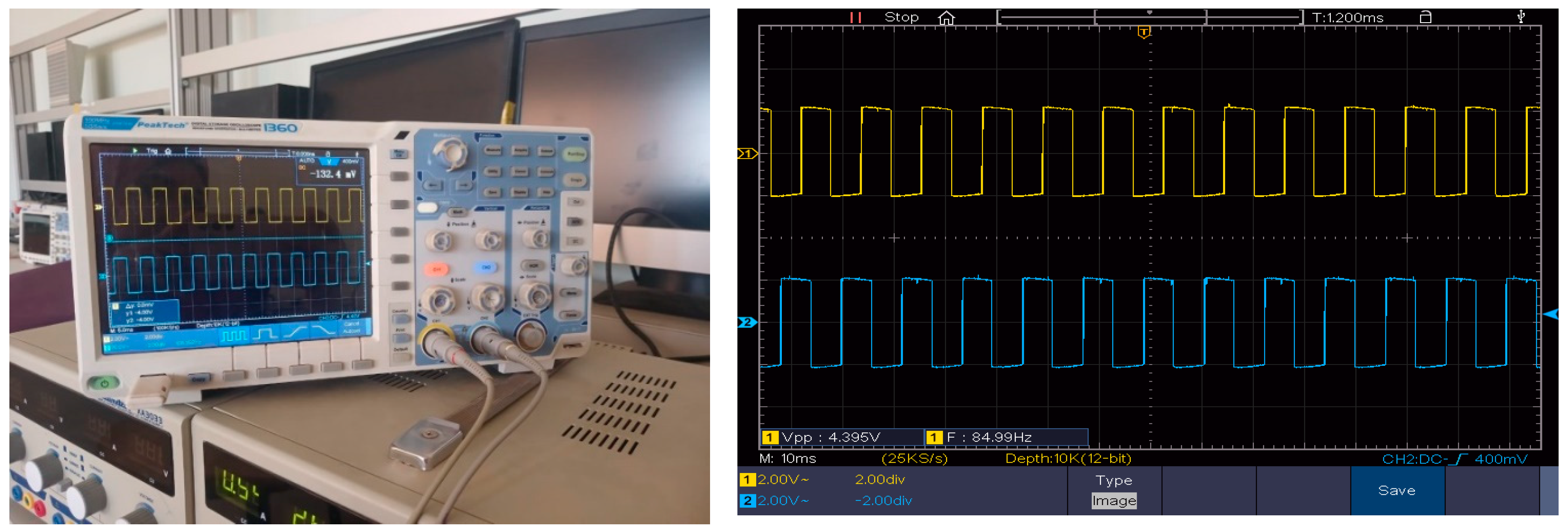
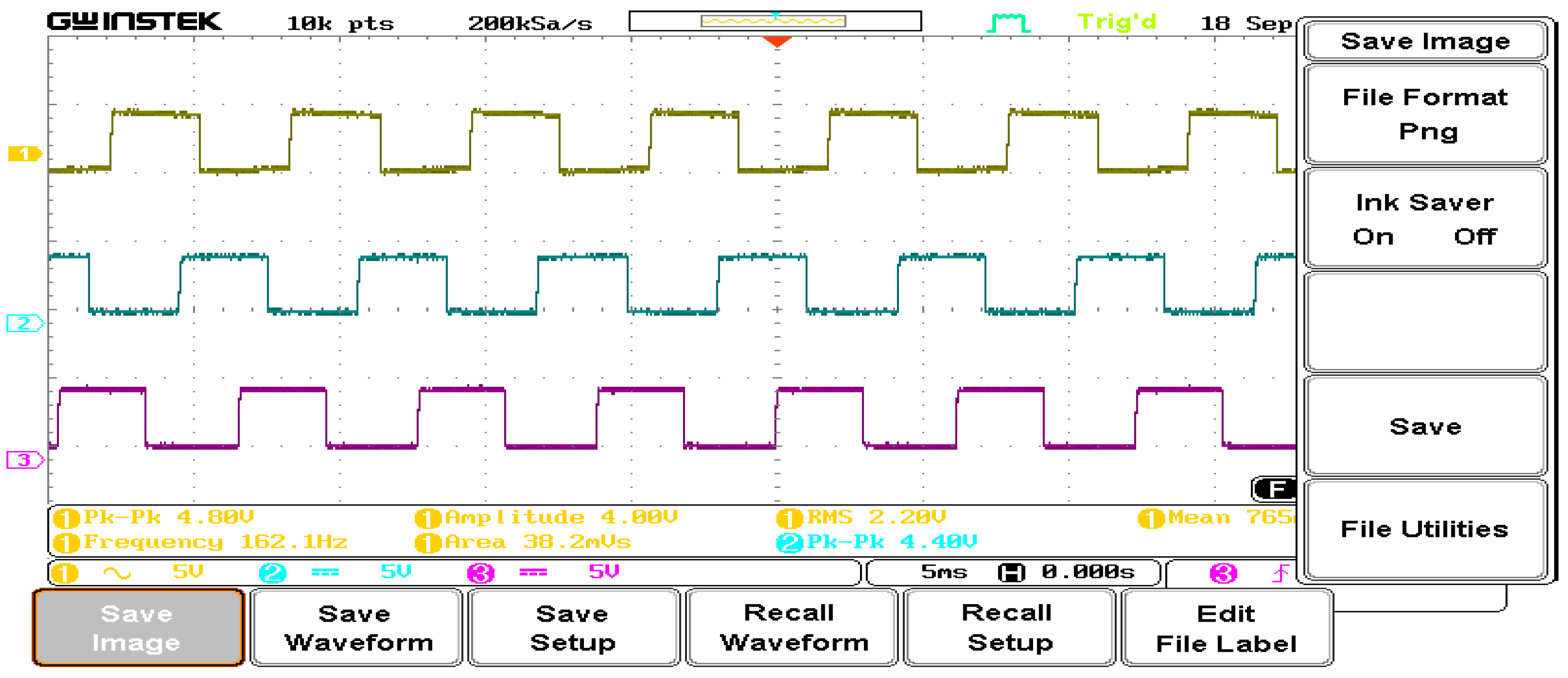
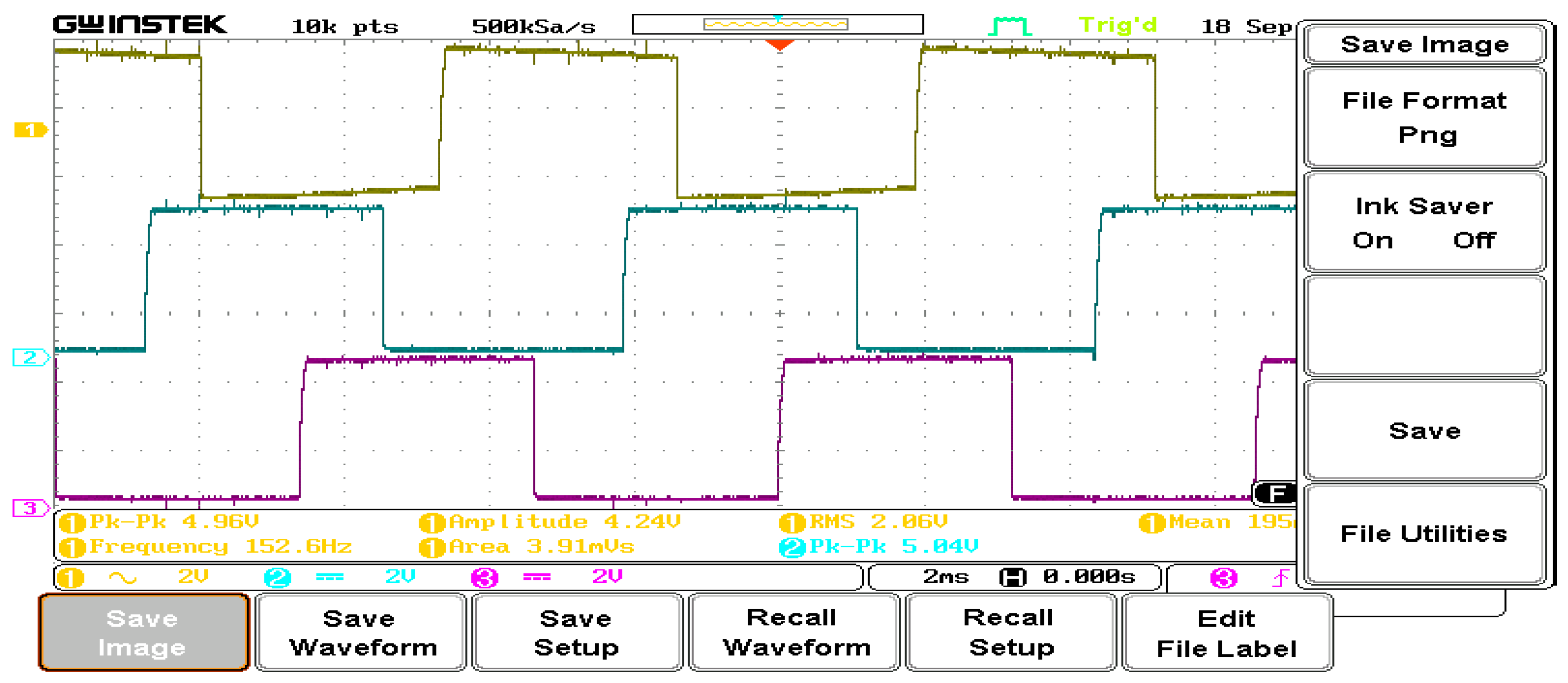
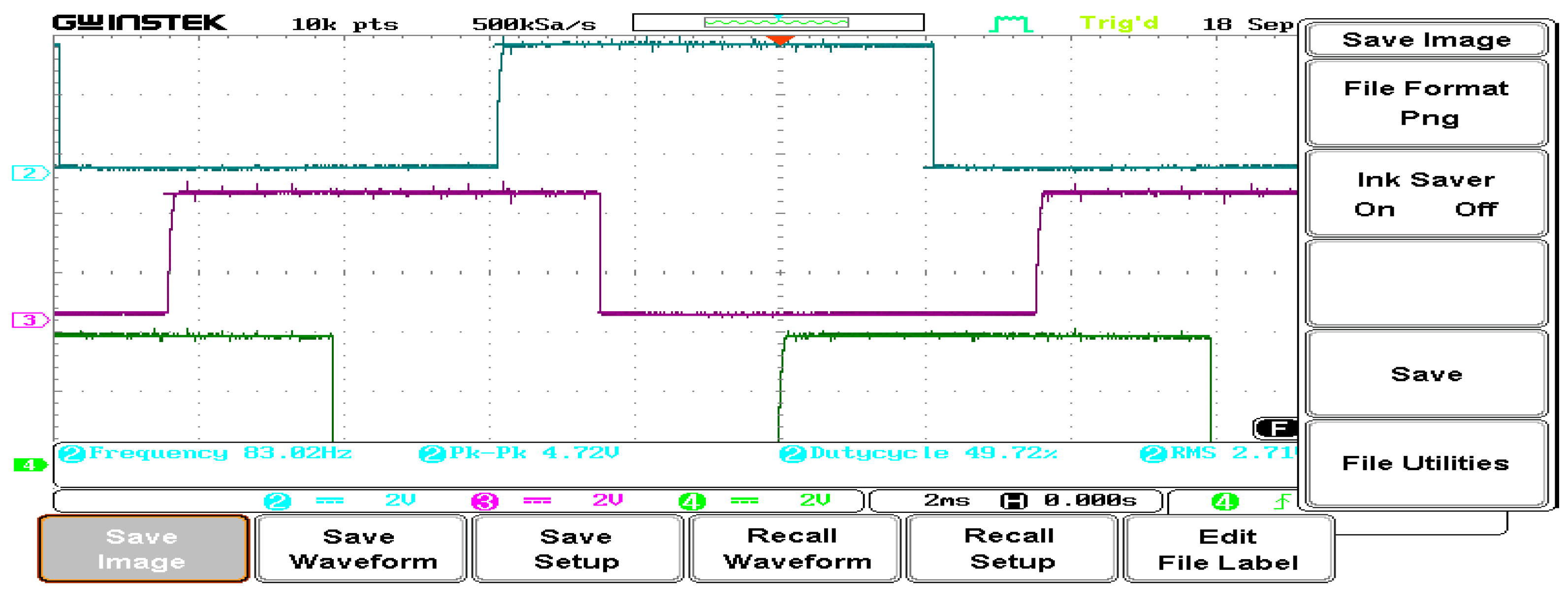
- The BLDC platform controls the Arduino motors to produce a PWM signal with a duty cycle of 0% to 100% and a frequency of 50Hz.
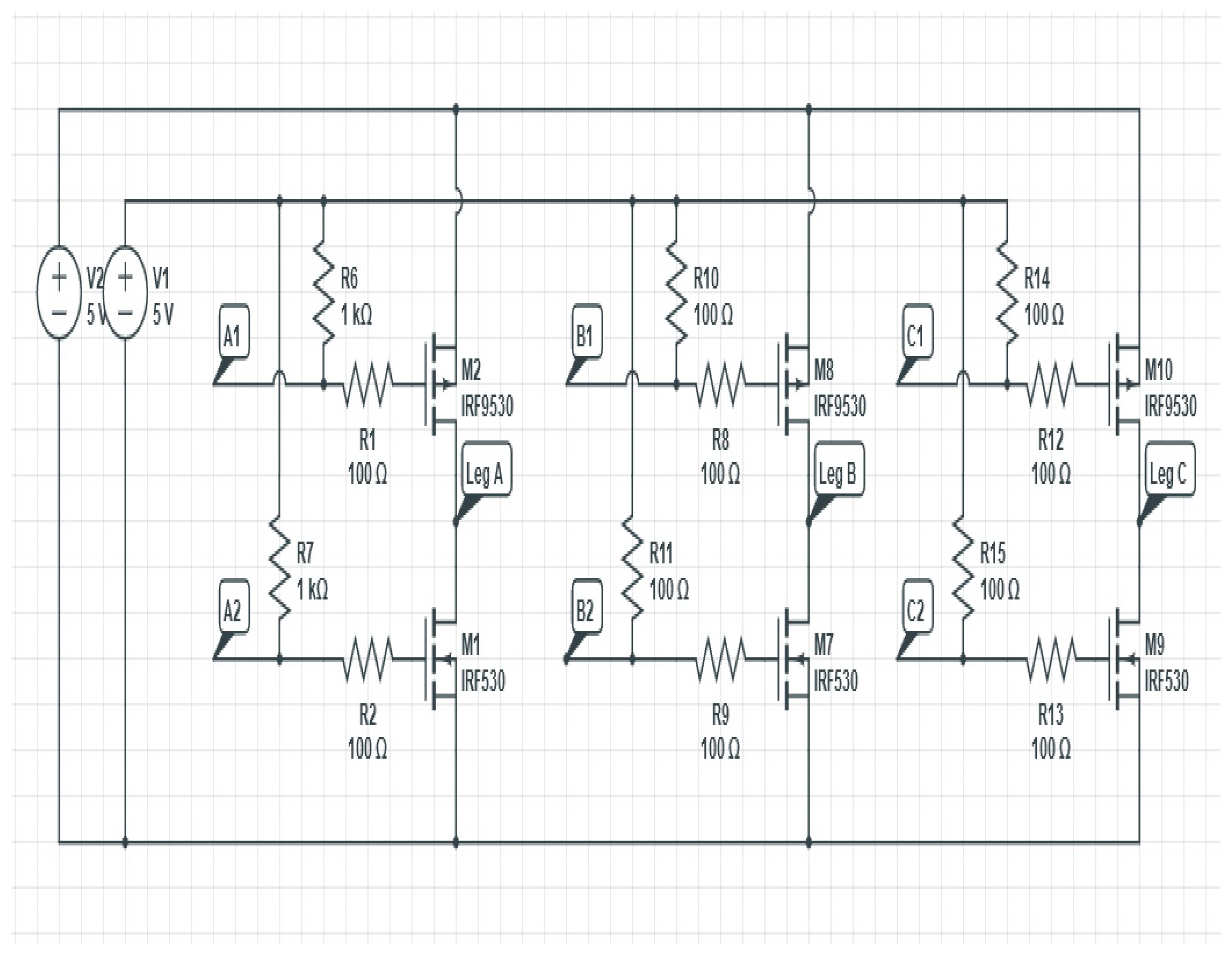
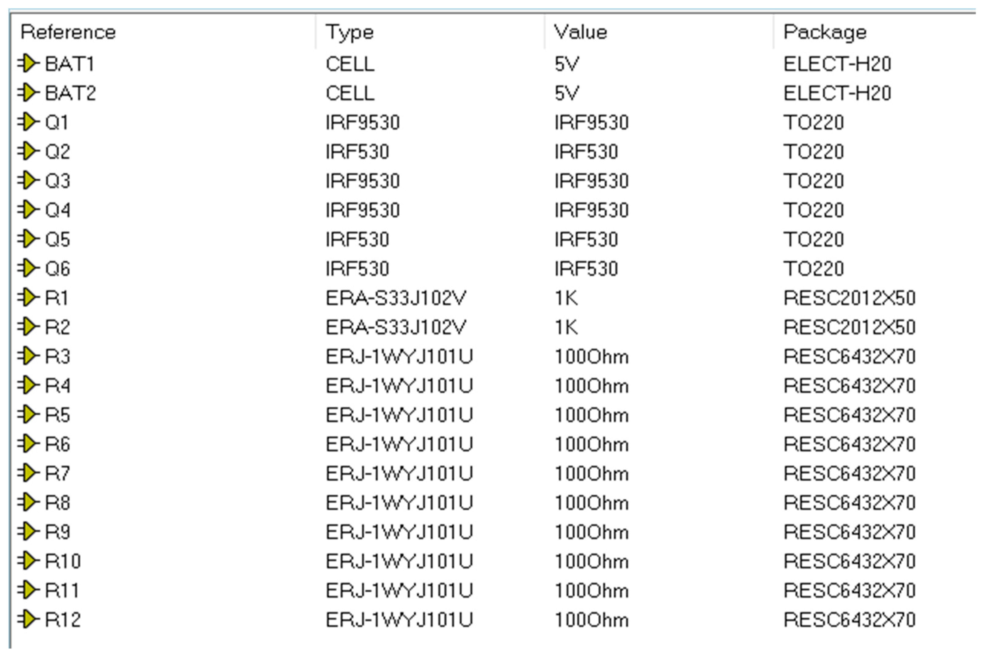
- Using the identical circuit settings used for simulation, an experimental prototype was put into practice to validate the simulation results. The gate pulses are generated with a time delay to prevent short circuits during switch operation.
2. Materials and Methods
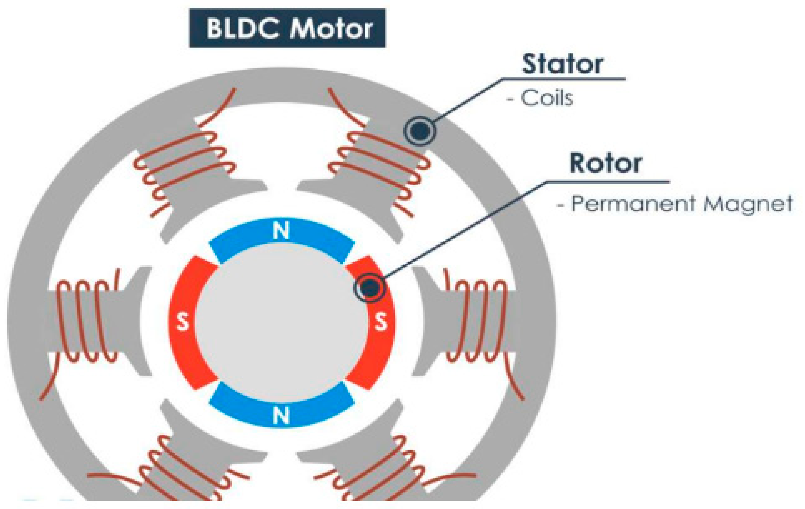
2.1. Types of BLDC Motor
2.2. Mathematical modeling of a BLDC motor
2.3. Model dynamic mathematical
2.4. Design of speed control with Limitation
2.5. Proposed system
3. Results and discussion
3.1. Simulation results
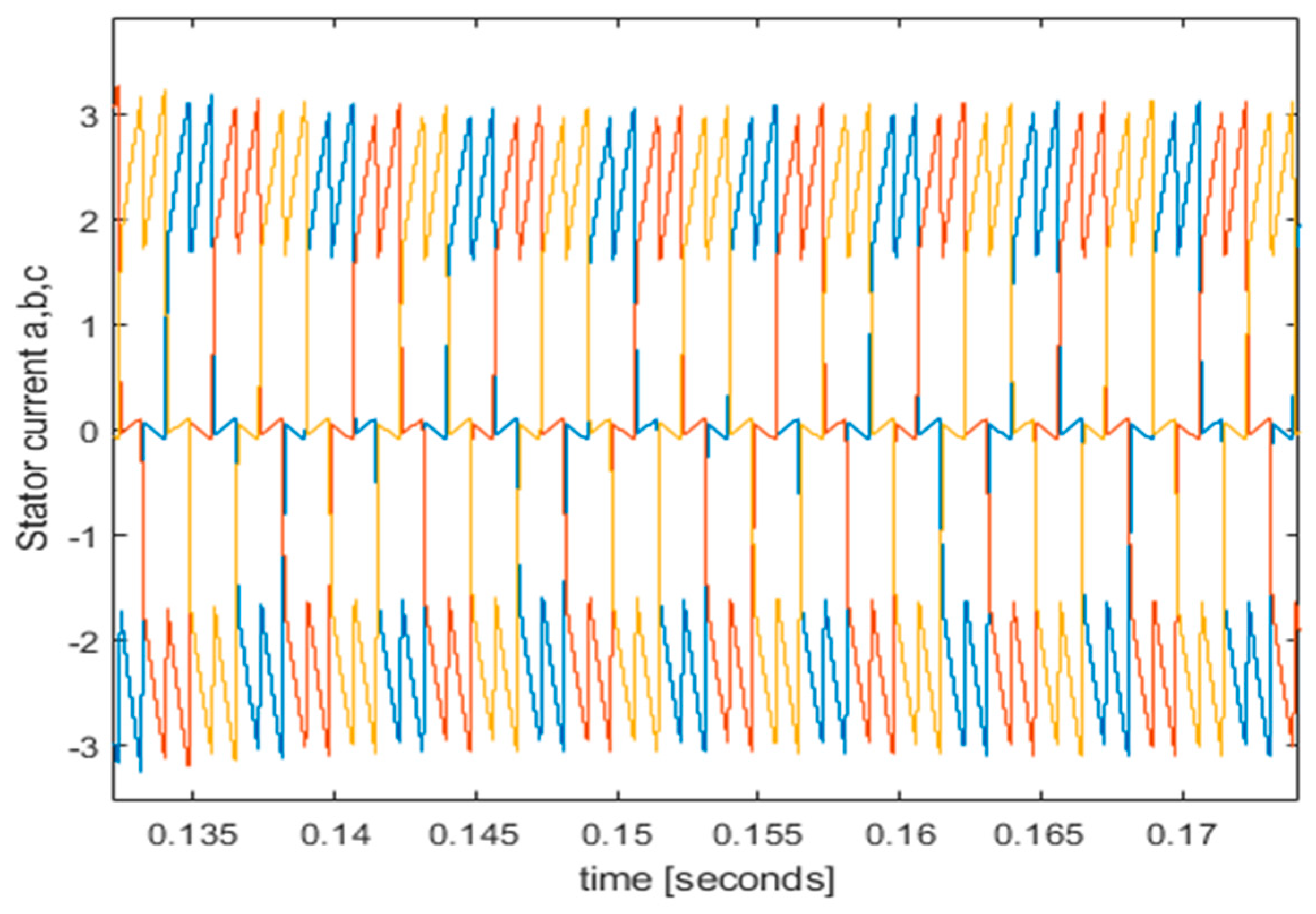
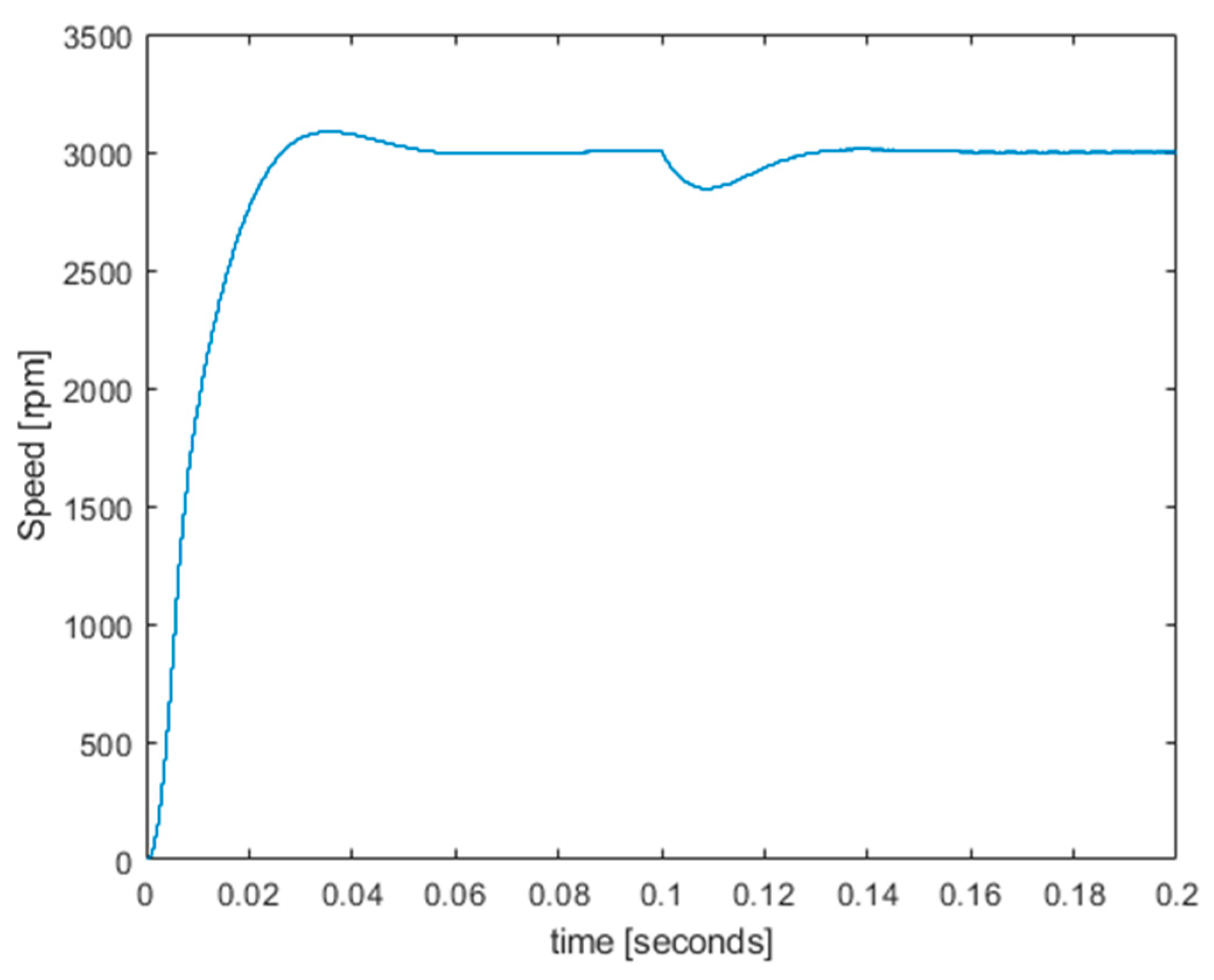
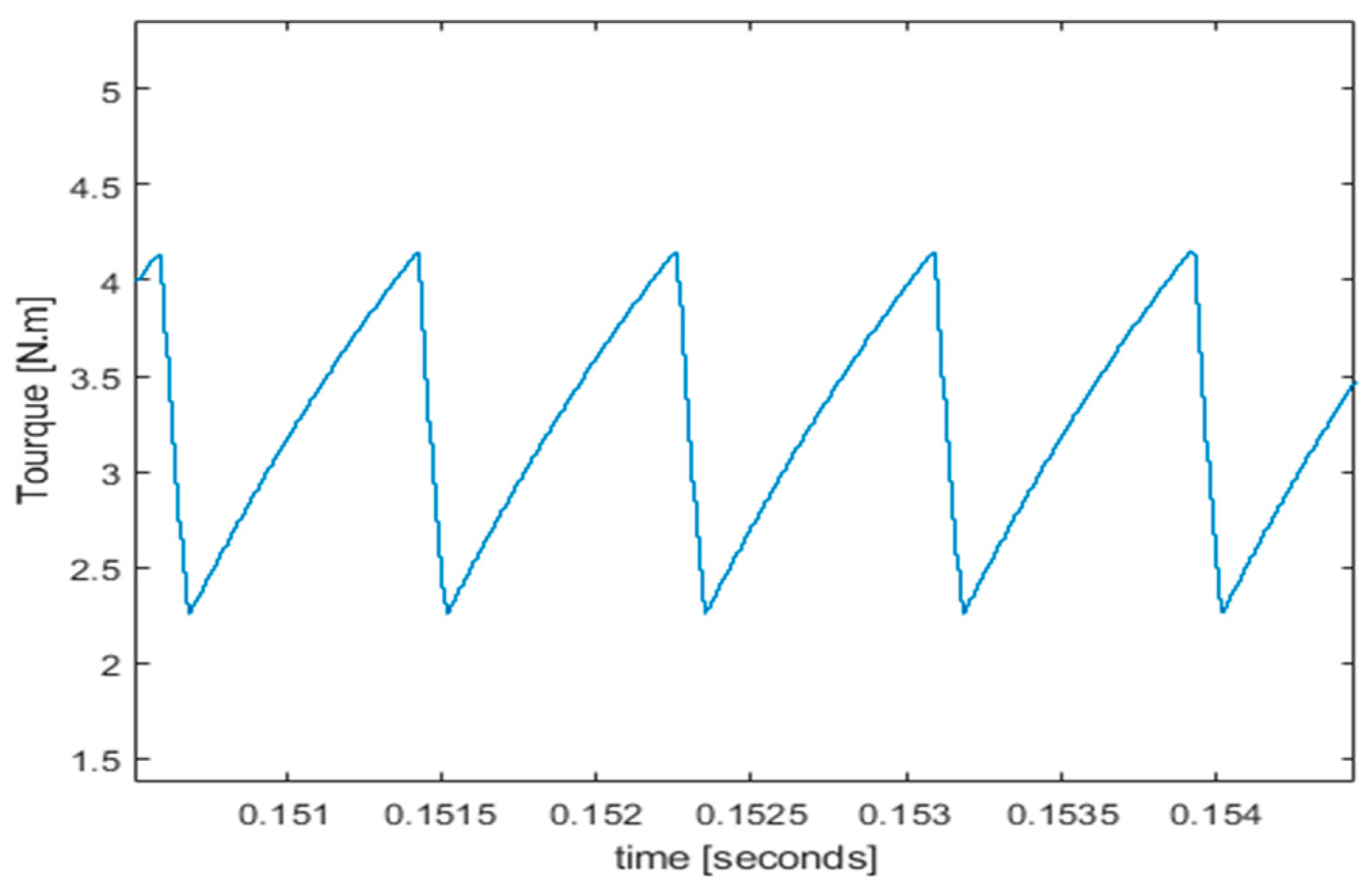
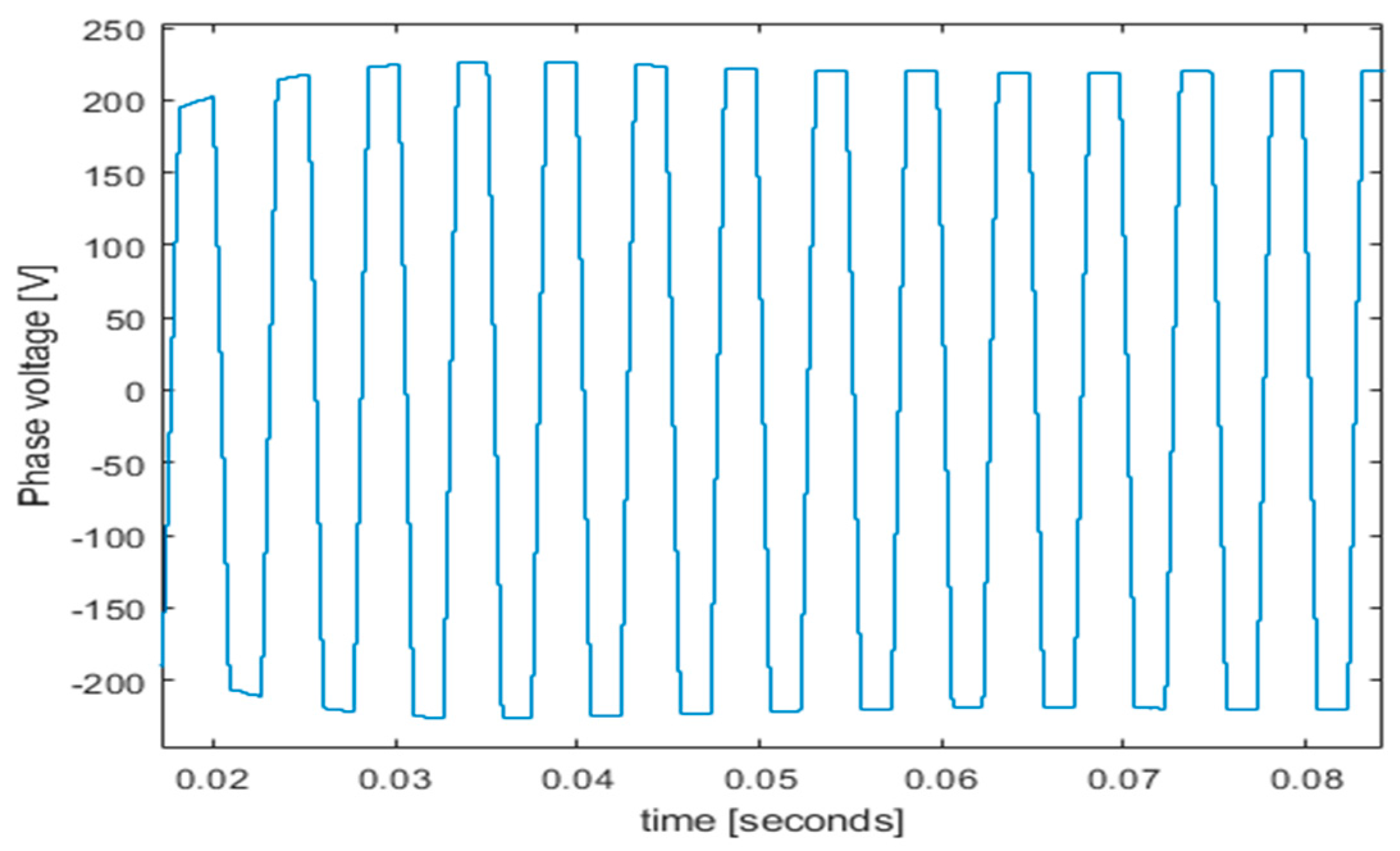
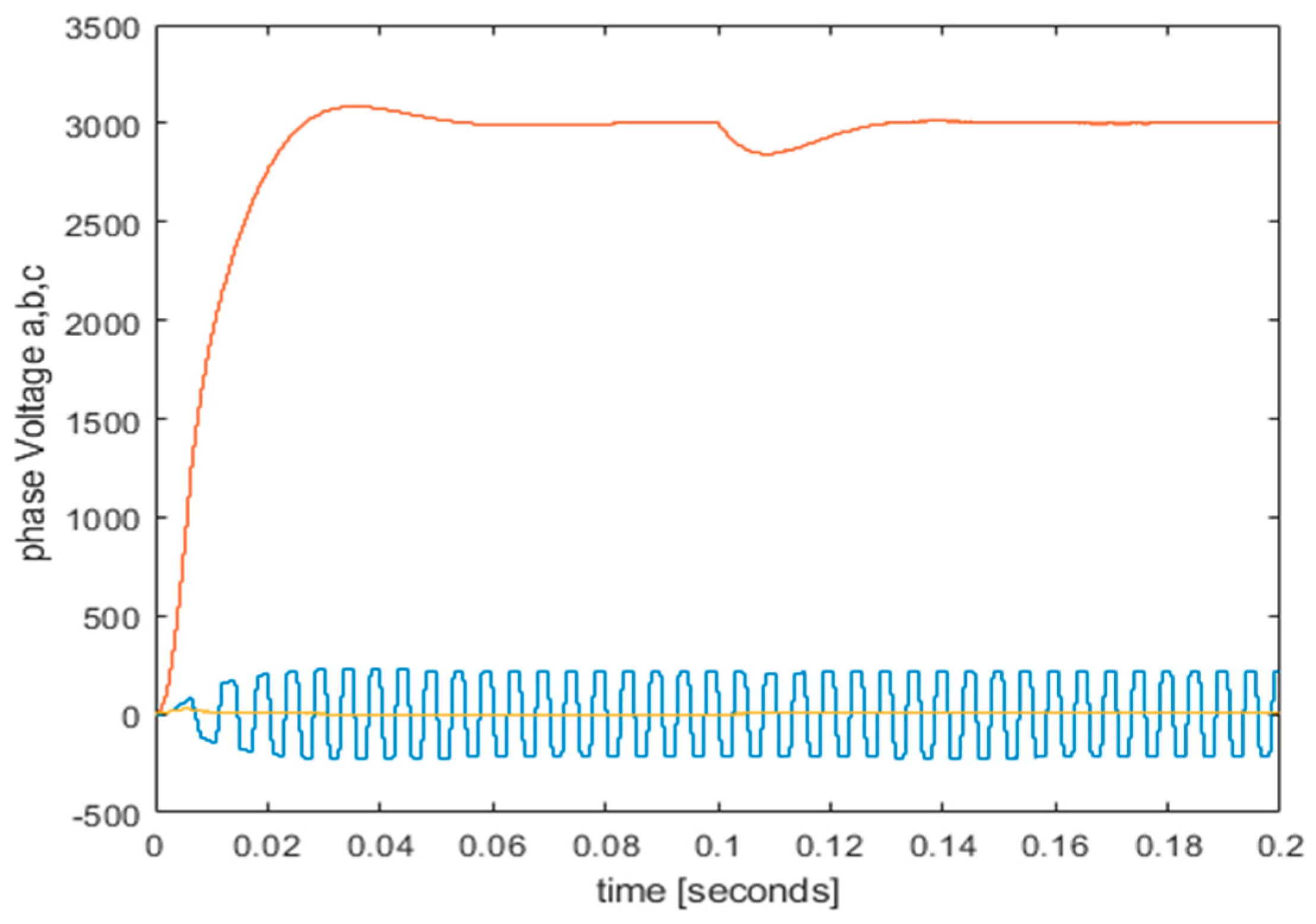
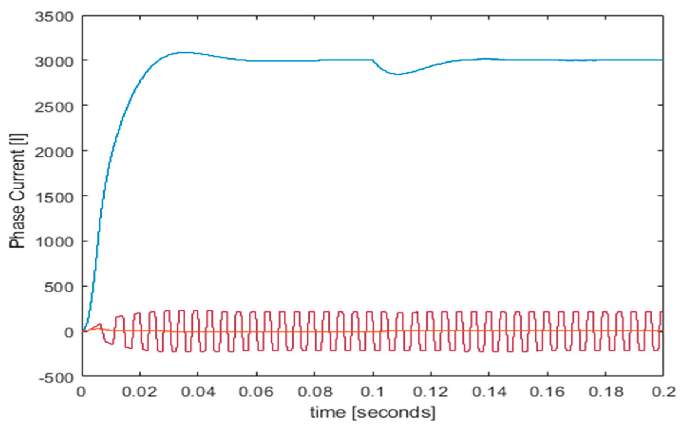
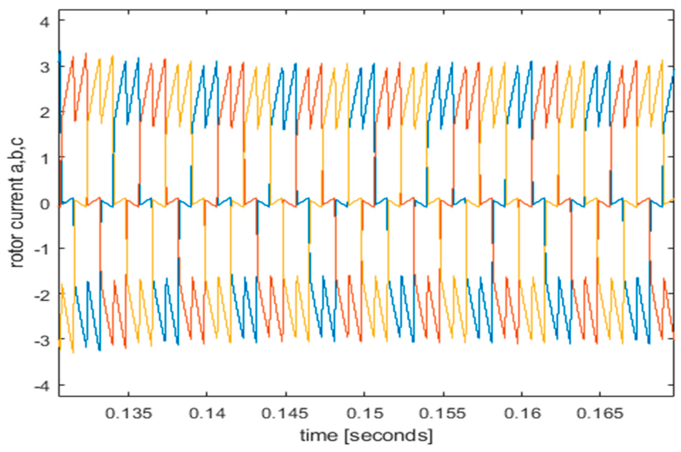
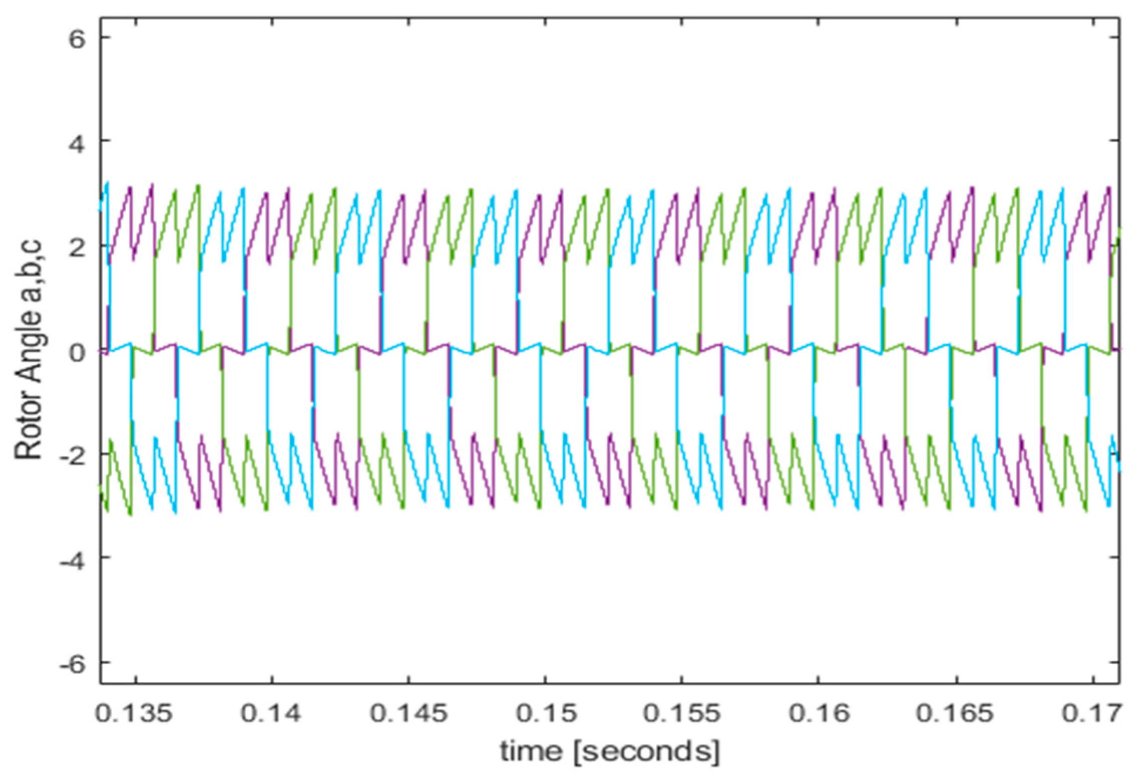
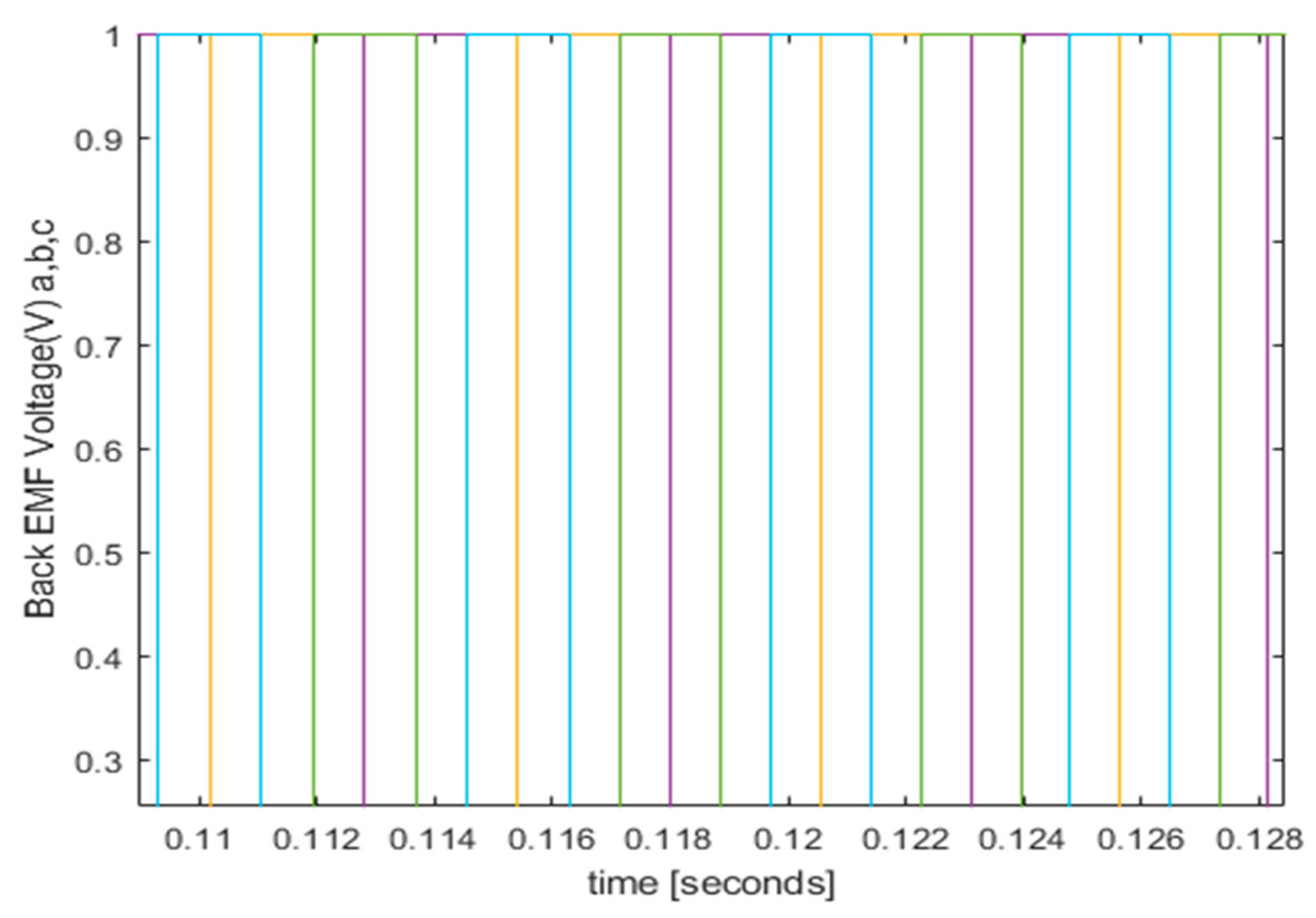
3.2. Experimental Setup
4. Conclusions
Author Contributions
Funding
Conflicts of Interest
Abbreviations
| AC | Alternating Current |
| DC | Direct Current |
| BLDCM | Brushless Direct Current Motor |
| PMBLDC | Permanent Magnet Brushless Direct Current |
| MOSFET | Metal Oxide Semiconductor Field Effect Transistor |
| EV | Electric Vehicle |
| BDC | Brushed Direct Current |
| IM | Induction Motor |
| SRM | Switching Reluctance Motor |
| RES | Renewable energy systems |
| PWM | Pulse Width Modulation |
| ICE | Internal Combustion Engine |
| EMI | Electro Magnetic Interference |
| VS | Voltage Source |
| CS | Current Source |
| kHz | kilo hertz |
| P | number of pulses |
| EMC | Electro Magnetic Compatibility |
| EMF | Electro Magnetic Field |
| MHz | Mega Hertz |
| PID | Proportional Integral and Derivative |
| MCU | Microcontroller Unit |
| IC | Integrated Circuit |
References
- Chow, C.C.T.; Ainslie, M.D.; Chau, K.T. High temperature superconducting rotating electrical machines: An overview. Energy Reports 2023, 9, 1124–1156. [CrossRef]
- Yang, D.; Huo, Y.; Zhang, Q.; Xie, J.; Yang, Z. Recent advances on air heating system of cabin for pure electric vehicles: A review. Heliyon 2022, 8, 1–11. [CrossRef]
- Rajesh, P.; Shajin, F.H.; Rajani, B.; Sharma, D. An optimal hybrid control scheme to achieve power quality enhancement in microgrid connected system. Int. J. Number Model Electron Netw Dev Fields 2022, 35, e3019.
- Jayakumar, V.; Chokkalingam, B.; Munda, J.L. A Comprehensive Review on Space Vector Modulation Techniques for Neutral Point Clamped Multi-Level Inverters. IEEE Access 2021, 9, 112104–112144. [CrossRef]
- Aliasand, A.E.; Josh, F. Selection of motor for an electric vehicle: A review. Materials Today: Proceedings 2020, 24, 1804–1815. [CrossRef]
- Sheng, Y.; Wang, X.; Wang, L.; Hou, P. Fuzzy-PID control system design of brushless DC motor based on vector control. Chinese automation congress (CAC), Jinan, China, 5583-5587.
- Chen, Q.; Liu, G.; Zhao, W.; Qu, L.; G. Xu. Asymmetrical SVPWM fault-tolerant control of five-phase PM brushless motors. IEEE Transactions on Energy Conversion 2016, 3, 12–22. [CrossRef]
- Sriram, J.; Sureshkumar, K. Speed control of BLDC motor using fuzzy logic controller based on sensorless technique. International Conference on Green Computing Communication and Electrical Engineering (ICGCCEE), Coimbatore, India, 2014, 1-6.
- Goswami, R.; Joshi, D. Performance review of fuzzy logic based controllers employed in brushless DC motor. Procedia computer science, 2018, 132, 623–631. [CrossRef]
- Yong, Z.; Man, W.; Qi, L.; Chao, Z. The design of BLDCM controller for EMA based on fuzzy PID control. Chinese Control and Decision Conference (CCDC), Yinchuan, China, 2016, 6428-6432.
- Devi, K.S.; Dhanasekaran, R.; Muthulakshmi, S. Improvement of speed control performance in BLDC motor using fuzzy PID controller. International Conference on Advanced Communication Control and Computing Technologies (ICACCCT), Ramanathapuram, India, 2016, 380-384.
- Whittingham, M.S. History, evolution, and future status of energy storage. Proceedings of the IEEE, 2012, 100, 1518–1534. [CrossRef]
- Singh, B. Recent advances in permanent magnet brushless DC motors. Sadhana 1997, 22, 837–853. [CrossRef]
- Miller, T.J. Brushless permanent-magnet and reluctance motor drives. Oxford University Press, 1989.
- Blinov, D.; Borzenko, V.; Bezdudny, A. Experimental research of metal hydride heat storage reactor processes. in Journal of Physics: Conference Series 2021, 2039, 012004. [CrossRef]
- Bertoluzzo, M.; Buja, G.; Cossalter, V.; Doria, A.; Mazzaro, D. Getting around in electric vehicles. IEEE Industrial Electronics Magazine 2008, 2, 10–18.
- Pal, S. Comparative study of the design and development of direct drive brushed and brushless DC motors with samarium cobalt, neodymium-iron-boron and ceramic magnets. in conf. IEE Colloquium on Permanent Magnet Machines and Drives, London, UK, 1993, 1-7.
- Oman, H.; Simpson-Clark, R. Permanent magnets for vehicle-propulsion motors: cost/availability. in IECEC 96. Proceedings of the 31st Intersociety Energy Conversion Engineering Conference, Washington, DC, USA, 1996, 91-96.
- Kenjō, T.; Nagamori, S. Permanent-magnet and brushless DC motors. Clarendon Press. Oxford, 1985, 18.
- Skvarenina, T.L. The power electronics handbook. CRC Press, 2018.
- Rajashekara, K. History of electric vehicles in General Motors. IEEE Transactions on Industry Applications 1994, 30, 897–904.
- Chan, C.; Chau, K. Modern electric vehicle technology. Oxford University Press, 2001, 47.
- Chan, C. An overview of electric vehicle technology. Proceedings of the IEEE 1993, 81, 1202–1213. [CrossRef]
- Chan, C. Present status and future trends of electric vehicles. 2nd International Conference on Advances in Power System Control, Operation, and Management, APSCOM-93., Hong Kong, 1993, 456-469.
- Appelbaum, J.; Sarma, M. The operation of permanent magnet DC motors powered by a common source of solar cells. IEEE Transactions on Energy Conversion 1989, 4, 635–642. [CrossRef]
- Dawson, C.; Bolton, H. Performance prediction of a wide-angle limited-motion rotary actuator. in Proceedings of the Institution of Electrical Engineers 1978, 125, 895 – 898. [CrossRef]
- Dawson, C.; Bolton, H. Design of a class of wide-angle limited-rotation rotary actuators. in Proceedings of the Institution of Electrical Engineers 1979, 126, 345–350. [CrossRef]
- Tokunaga, D.; Kesamaru, K. Development of novel PM motors for sport type electric motorcycles. 15th International Conference on Electrical Machines and Systems (ICEMS), Sapporo, Japan, 2012, 1-4.
- Akhil, M.; Aishwarya, V.; Sheela, K.G. An Improved SEPIC- Based Single Switch Buck-Boost PFC Converter Fed Brushless DC Motor Drive. Materials Today: Proceedings 2020, 24, 1855–1864. [CrossRef]
- Krishnan, R. Electric Motor Drives Modeling, Analysis, and Control. Prentice Hall, 2001.
- Murai, Y.; Kawase, Y.; Ohashi, K. Torque ripple improvement for brushless DC miniature motors. IEEE Transactions on Industry Applications 1989, 25, 441–450. [CrossRef]
- Park, S.I.; Kim, T.S.; Ahn, S.C.; Hyun, D.S. An improved current control method for torque improvement of high-speed BLDC motor. IEEE 18th Applied Power Electronic Conference and Exposition, Miami Beach, FL, USA, 2003, 294-299.
- Rodriguez, F.; Emadi, A. A novel digital control technique for brushless DC motor drives. IEEE Transactions on Industrial Electronics 2007, 54, 365–2373.
- Pindoriya, R.M.; Rajendran, S.; Chauhan, P.J. Field programmable gate array-based speed control of BLDC motor. IEEE Innovative Smart Grid Technologies - Asia (ISGT ASIA), Bangkok, Thailand, 2015, 1-6.
- Tashakori, A.; Hassanudeen, M.; Ektesabi, M. FPGA based controller drive of BLDC motor using digital PWM technique. IEEE 11th International Conference on Power Electronics and Drive Systems, Sydney, NSW, Australia, 2015, 658-662.
- Li, Z.B.; Lu, W.; Gao, L.F.; Zhang, J.S. Nonlinear state feedback control of chaos system of brushless DC motor. Procedia computer science 2021, 183, 636–640. [CrossRef]
- Wang, X.; Tallam, R.; Shrivastava, A.; Morris, G. Reliability test setup for liquid aluminum electrolytic capacitor testing. Annual Reliability and Maintainability Symposium (RAMS), Orlando, FL, USA, 2019, 1-5.
- Jo, S.T.; Shin, H.S.; Lee, Y.G.; Lee, J.H.; Choi, J.Y. Optimal design of a BLDC motor considering three-dimensional structures using the response surface methodology. Energies 2022, 15, 461. [CrossRef]
- Lee, T.Y.; Seo, M.K.; Kim, Y.J.; Jung, S.Y. Motor design and characteristics comparison of outer-rotor-type BLDC motor and BLAC motor based on numerical analysis. IEEE Trans. Appl. Supercond. 2016, 26, 1–6. [CrossRef]
- Behera, R.K.; Kumar, R.; Bellala, S.M.; Raviteja, P. Analysis of electric vehicle stability effectiveness on wheel force with BLDC motor drive. in Proc. IEEE Int. Conf. Ind. Electron. Sustain. Energy Syst. (IESES), Hamilton, New Zealand, 2018, 195–200.
- Yedamale, P. Brushless DC (BLDC) motor fundamentals. Microchip Technology Inc 2003, 20, 3–15.
- Aresta, M.; Dibenedetto, A.; Quaranta, E. State of the art and perspectives in catalytic processes for CO2 conversion into chemicals and fuels: The distinctive contribution of chemical catalysis and biotechnology. Journal of Catalysis 2016, 343, 2–45. [CrossRef]
- Pillay, P.; Krishnan, R. Modeling of permanent magnet motor drives. IEEE Transactions on industrial electronics 1988, 35, 537–541.
- Attar, A.; Bouchnaif, J.; Grari, K. Control of Brushless DC motors using sensorless Back-EMF integration method. Materials Today: Proceedings 2021, 45, 7438–7443. [CrossRef]
- Bayardo, R.G.; Loukianov, A.G.; Fuentes-Aguilar, R.Q.; Utkin, V.I. Adaptive speed tracking controller for a brush-less DC motor using singular perturbation. IFAC Papers Online 2020, 53, 3880–3885. [CrossRef]
- Yumashev, A.; Mikhaylov, A. Development of polymer film coatings with high adhesion to steel alloys and high wear resistance. Polymer Composites 2020, 41, 2875–2880. [CrossRef]
- Bhuiyan, M.A.; Zh., Q.; Khare, V.; Mikhaylov, A.; Pinter, G.; Huang, X. Renewable Energy Consumption and Economic Growth Nexus—A Systematic Literature Review. Frontiers in Environmental Science 2022, 10, 878394. [CrossRef]
- Dinçer, H.; Yüksel, S.; Mikhaylov, A.; Pinter, G.; Shaikh, Z.A. Analysis of renewable-friendly smart grid technologies for the distributed energy investment projects using a hybrid picture fuzzy rough decision-making approach. Energy Reports 2022, 8, 11466–11477. [CrossRef]
- Wang, Q.; Guo, J.; Li, R.; Mikhaylov, A.; Moiseev, N. Does technical assistance alleviate energy poverty in sub-Saharan African countries? A new perspective on spatial spillover effects of technical assistance. Energy Strategy Reviews 2023, 45, 101047. [CrossRef]
- He, H.; Huang, Y.; Nakadomari, A.; Masrur, H.; Krishnan, N.; Hemeida, A.M.; Mikhaylov, A.; Senjyu, T. Potential and economic viability of green hydrogen production from seawater electrolysis using renewable energy in remote Japanese islands. Renewable Energy 2023, 202, 1436–1447. [CrossRef]
- Rimpas, D.; Kaminaris, S.D.; Piromalis, D.D.; Vokas, G.; Arvanitis, K.G.; Karavas, C.S. Comparative Review of Motor Technologies for Electric Vehicles Powered by a Hybrid Energy Storage System Based on Multi-Criteria Analysis. Energies 2023, 16, 2555. [CrossRef]
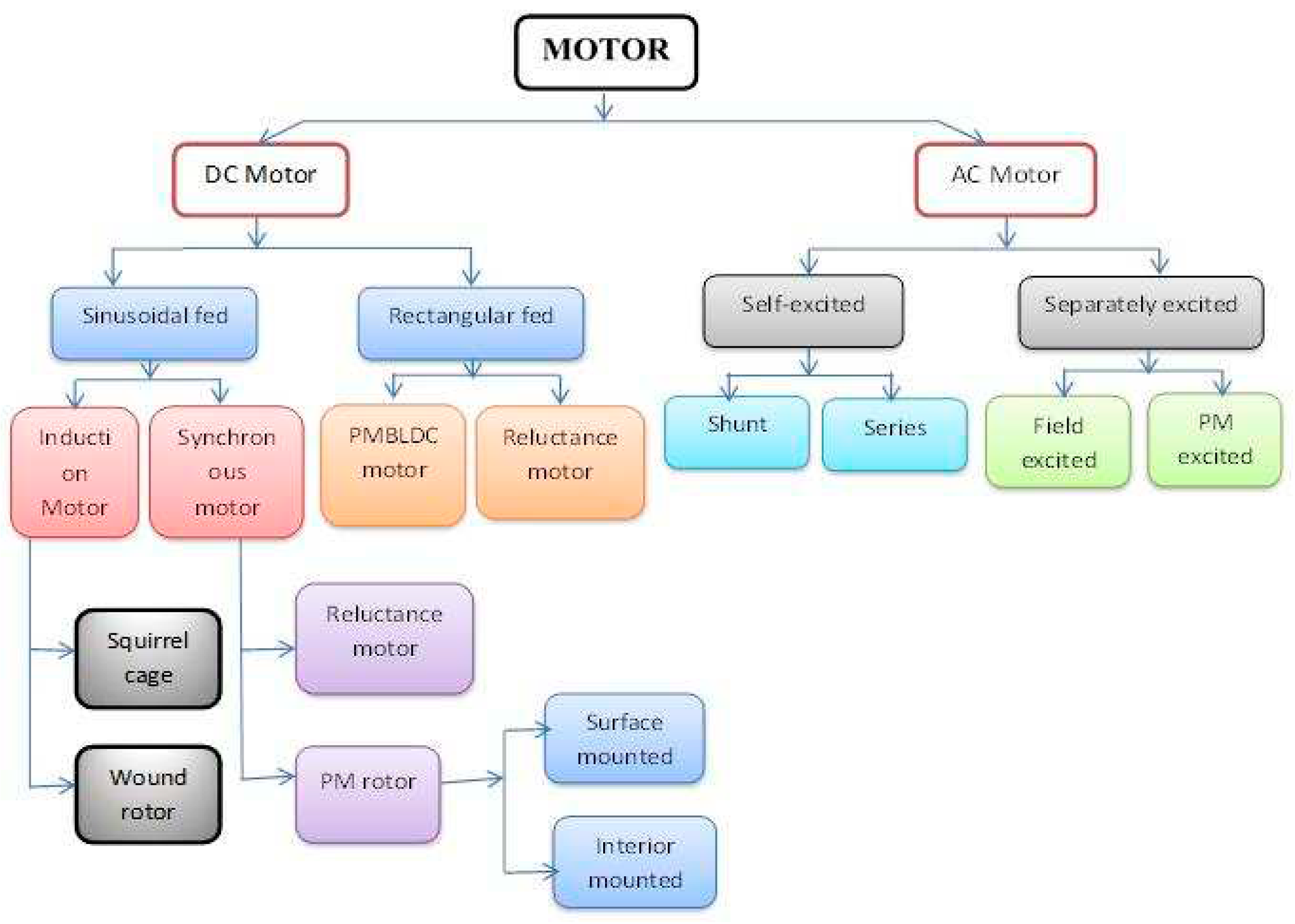
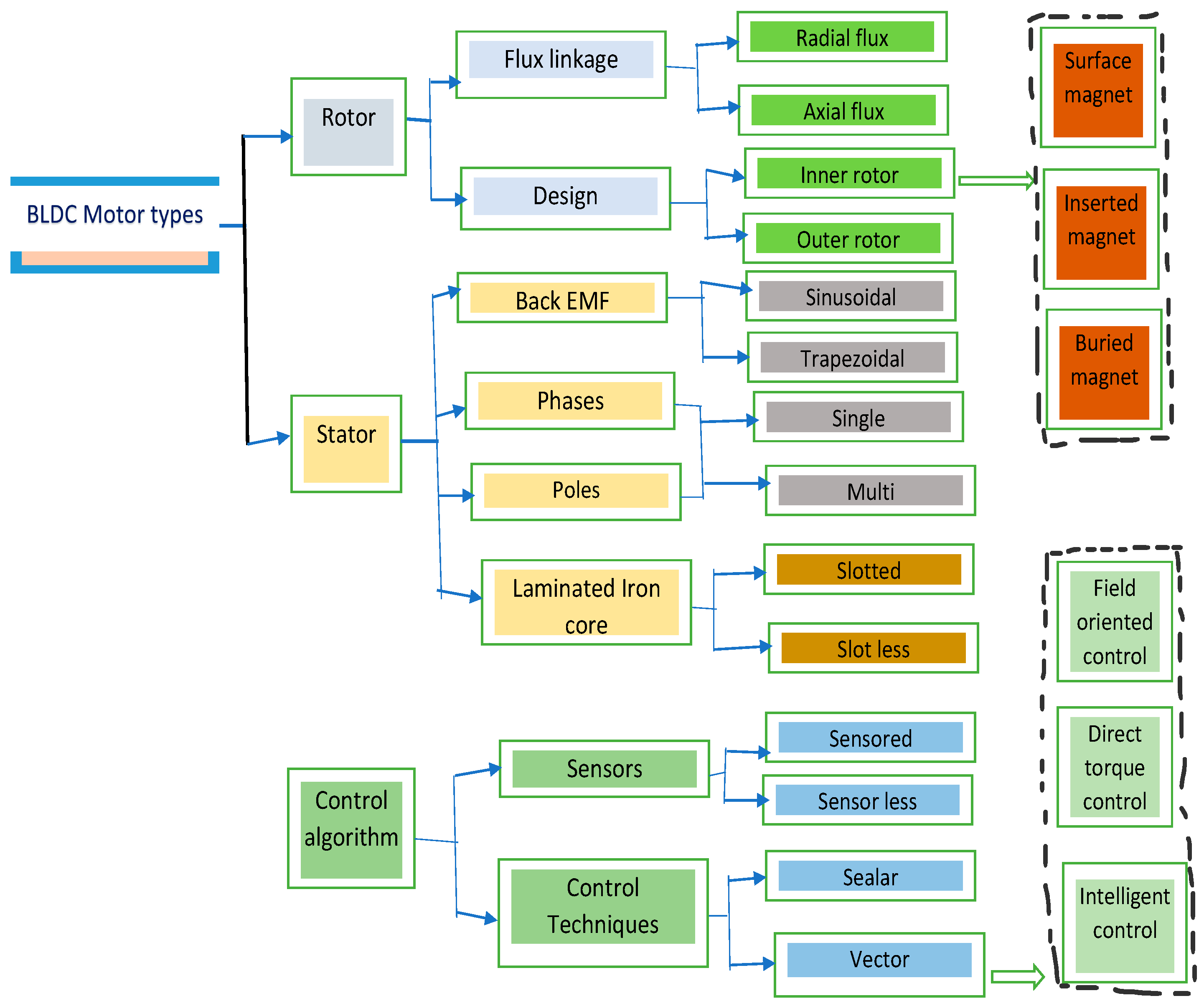
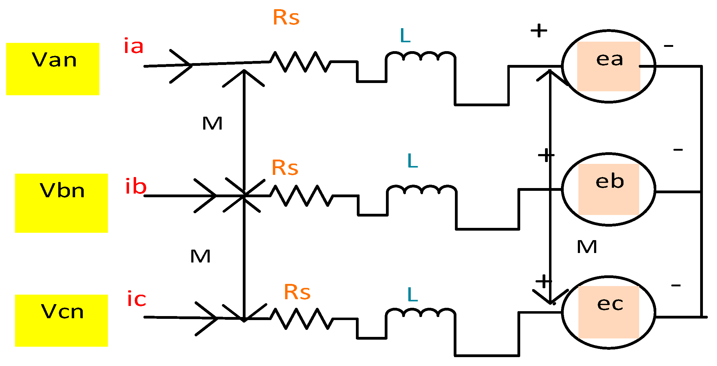

| Features | BLDC motor | SR motor | Induction motor | DC motor |
|---|---|---|---|---|
| Commutation | Electronic | electronic | - | Brushes |
| Slip | - | - | Applicable | - |
| Efficiency | 5 | 3 | 3 | 2 |
| high-speed rating | 5 | 5 | 3 | 3 |
| broader steady power speed range | 3 | 5 | 4 | 2 |
| Complexity of control | 2 | 2 | 3 | 5 |
| Torque/Speed | 5 | 3 | 4 | 3 |
| A responsive dynamic | 5 | 2 | 3 | 4 |
| Power-to-size ratio | 4 | 4 | 3 | 3 |
| The lifetime of an operation | 5 | 5 | 3 | 2 |
| maintenance requirements | 5 | 5 | 4 | 2 |
| Sensitivity to noise | 5 | 2 | 3 | 3 |
| In fault Speed | 3 | 5 | 4 | 2 |
| Torque during a fault | 4 | 2 | 4 | 1 |
| Speed during mechanical shocks | 3 | 4 | 5 | 4 |
| Torque during mechanical shocks | 4 | 2 | 3 | 3 |
| Cost of Production | 2 | 4 | 5 | 5 |
| Total | 60 | 53 | 54 | 44 |
Disclaimer/Publisher’s Note: The statements, opinions and data contained in all publications are solely those of the individual author(s) and contributor(s) and not of MDPI and/or the editor(s). MDPI and/or the editor(s) disclaim responsibility for any injury to people or property resulting from any ideas, methods, instructions or products referred to in the content. |
© 2023 by the authors. Licensee MDPI, Basel, Switzerland. This article is an open access article distributed under the terms and conditions of the Creative Commons Attribution (CC BY) license (http://creativecommons.org/licenses/by/4.0/).


