Preprint
Article

Dynamic Behavior Modeling of Natural Rubber/Polybutadiene Rubber-Based Hybrid Magnetorheological Elastomer Sandwich Composite Structures

Altmetrics

Downloads

108

Views

80

Comments

0

A peer-reviewed article of this preprint also exists.

Submitted:

19 October 2023

Posted:

20 October 2023

You are already at the latest version

Alerts
Abstract
This study investigates the dynamic characteristics of Natural Rubber (NR)/Polybutadiene Rubber (PBR) based hybrid magnetorheological elastomer (MRE) sandwich composite beams through numerical simulations and finite element analysis, employing Reddy's third-order shear defor-mation theory. Four distinct hybrid MRE sandwich configurations were examined. The validity of finite element simulations was confirmed by comparing them with results from magnetorheo-logical (MR) fluid-based composites. Further, parametric analysis explored the influence of magnetic field intensity, boundary conditions, ply orientation, and core thickness on beam vi-bration responses. Results reveal a notable 10.4% enhancement in natural frequencies in SC4-based beams under a 600mT magnetic field with clamped-free boundary conditions, attributed to in-creased PBR content in MR elastomer cores. However, higher magnetic field intensities result in slight frequency decrements due to filler particle agglomeration. Additionally, augmenting magnetic field intensity and magnetorheological content under clamped-free conditions improves the loss factor by 66% to 136%, presenting promising prospects for advanced applications. This research contributes to a comprehensive understanding of dynamic behavior and performance enhancement in hybrid MRE sandwich composites, holding significant implications for engi-neering applications. Furthermore, this investigation provides valuable insights into the intricate interplay between magnetic field effects, composite architecture, and vibration response.
Keywords: 
Subject: Engineering  -   Aerospace Engineering

1. Introduction

Advances in aerospace technology have led to the development of composite materials that feature properties that rival or even surpass those of traditional materials, notably fiber-reinforced polymers (FRPs). FRPs are renowned for their remarkable attributes, including a high strength-to-weight ratio, exceptional durability, stiffness, and resistance to corrosion, wear, and impact. However, these high-performance FRP composite structures face a formidable challenge—vibrations induced by dynamic loads. These vibrations often lead to resonance conditions and the risk of catastrophic failures, exacerbated by insufficient damping characteristics. In response to these critical challenges, the development of smart materials has emerged as alternative materials aimed at enhancing the performance, structural integrity, and overall comfort of composite structures. Among these smart materials, MR materials have gained prominence due to their field-dependent rheological properties [1,2].
In the past decade, magneto-rheological materials have gained significant attention, surpassing electrorheological (ER) materials. This shift in interest is attributed to their superior yield strength, resilience to temperature variations, and tolerance to contaminants compared to ER fluids, making them ideal for controlling structural vibrations. Significant research endeavors have focused on evaluating both the properties and practical applications of MR fluids in the domain of structural vibration control [3,4]. However, the use of MR fluids is constrained by issues such as the accumulation of iron particles in the absence of a magnetic field and their relatively high production costs. While MR gels and grease offer exceptional performance, they are susceptible to issues like sedimentation, deposition, environmental pollution, and sealing problems [5,6,7]. In contrast, MR elastomers (MREs), featuring rubber as their matrix material, excel in surmounting these challenges. They exhibit swift and reversible transformations, tunable stiffness, and advantageous viscoelastic properties in response to magnetic field application [8]. MREs provide several advantages, including lower manufacturing costs and the absence of iron particle accumulation, making them an appealing choice for various engineering applications.
In the development of Magnetorheological Elastomers (MREs), the composition plays a pivotal role in shaping their characteristics. Chen et al. [9] emphasized the significant impact of both the applied magnetic field and the iron particle content on MRE damping properties, offering insights into the intricate interplay between magnetic field intensity and material composition. The essential structure of MREs, characterized by a matrix of rubber intricately mixed with dispersed magnetic particles, has been elucidated by various researchers [10,11], highlighting the critical role of this composite structure in shaping MRE behavior. Several variables come into play when molding the properties of MREs, including the choice of magnetic filler material, the matrix type, and the compatibility of the magnetic filler with the matrix. Typically, iron particles of diverse shapes and sizes, exhibiting ferromagnetic properties with high magnetic saturation and soft magnetic attributes, emerge as the preferred choice for MREs [9,12]. Furthermore, the exceptional magnetorheological performance of MREs can be attributed to the synergy between magnetic fillers and the matrix material [13]. Chen et al. has demonstrated that natural rubber-based MREs surpass silicone rubber-based counterparts across various properties, encompassing tear strength, tensile strength, resilience factor, and hardness [14]. Investigating isotropic synthetic rubber-based MREs, as shown by Gong et al., shows an impressive 26% enhancement in the Magnetorheological (MR) effect with the incorporation of 0.6 volume fraction of carbonyl iron (CI) particles. This enhancement undoubtedly signifies a marked improvement in the material’s rheological behavior. However, it does introduce a trade-off as it entails a reduction in its elastic properties [15]. This reduction in elasticity could be of concern, especially in structural applications where the ability to isolate vibrations is of paramount importance. MREs with diminished elastic properties may struggle to meet the demands for the necessary stiffness and structural integrity required to safeguard the overall system’s performance and reliability.
To overcome the limitations posed by reduced elastic properties in Magnetorheological Elastomers (MREs), extensive research has focused on incorporating various additives, including plasticizers, silane coupling agents, and nano-sized particles like carbon black, carbon nanotubes, and graphene [16,17,18,19,20]. These additives serve to enhance the mechanical properties of MREs by reinforcing the interfacial interactions between fillers and the elastomeric matrix; however, they are not exempt from significant challenges. One of these challenges lies in the propensity of these fillers, particularly when in nano-sized forms, to agglomerate within the elastomeric matrix [21]. This phenomenon not only complicates the manufacturing process but also escalates costs, particularly in the case of nanomaterials [22]. Ensuring compatibility between the chosen fillers and the matrix material, as well as addressing processing intricacies and potential health and environmental concerns, emerges as crucial considerations in MRE development. Achieving the delicate equilibrium between attaining desired properties and managing these inherent limitations constitutes a challenging task. Consequently, researchers are compelled to explore novel materials and innovative techniques continually, with the aim of optimizing MRE composites for a diverse array of applications.
In recent years, researchers have embarked on an exploration of the untapped potential within hybrid matrix Magnetorheological Elastomer (MRE) composites, aiming to conquer the persistent challenges posed by nanofillers and the relatively modest mechanical properties inherent in conventional MREs. This innovative approach has opened up a promising pathway for addressing these challenges associated with nanofillers and the relatively low mechanical properties observed in conventional MREs [23,24,25].
Researchers aimed to find a balance between the mechanical performance and Magnetorheological (MR) effect by using NR and PBR by addressing a common challenge in MRE development. NR-based MREs excel in mechanical properties but often fall short in terms of the required MR effect for industrial applications. In contrast, PBR-based MREs exhibit a high MR effect but suffer from inferior mechanical properties. The synergy between NR’s excellent synthetic mechanical performance and PBR’s desirable characteristics, including high elasticity, low heat buildup, cold resistance, and flex fatigue resistance, allows for the development of hybrid matrices that capitalize on the strengths of both materials. This harmonious blend results in improved compatibility, as NR and PBR share active cross-linking spots and possess similar vulcanization mechanisms and curing rates [26]. Song et al. research reveals that increasing polybutadiene rubber (PBR) content from 10% to 50% results in a minor decrease in the zero-field modulus, accompanied by a substantial enhancement in magneto-rheological (MR) effect, ranging from 31.25% to 44.19% [26]. This work underscores the trade-off between these critical material properties in hybrid MREs, with implications for future applications. Several works on matrix materials incorporating blends of NR/ styrene-butadiene rubber (SBR) and NR/ nitrile butadiene rubber (NBR) reveals the improved mechanical properties when compared to matrix composed of only NR or NBR [27]. Pal et al. showed the blends of Urethane Rubber (UR)/NR and PBR/NR exhibited 35-40% enhancement in mechanical properties [28]. The study by Ge et al. revealed that the incorporation of rosin glycerin ester into natural rubber/rosin glycerin hybrid matrix-based MREs resulted in an increase in the zero-field modulus (G0) at a 9% concentration, but this effect diminished at higher concentrations. Furthermore, an increase in carbon iron (CI) content led to a substantial 575% improvement in G0 at 80 wt%. Additionally, the application of a magnetic field intensified inter-particle forces within CI-based MREs, highlighting the potential for tailoring the mechanical properties of these materials for diverse engineering applications [29].
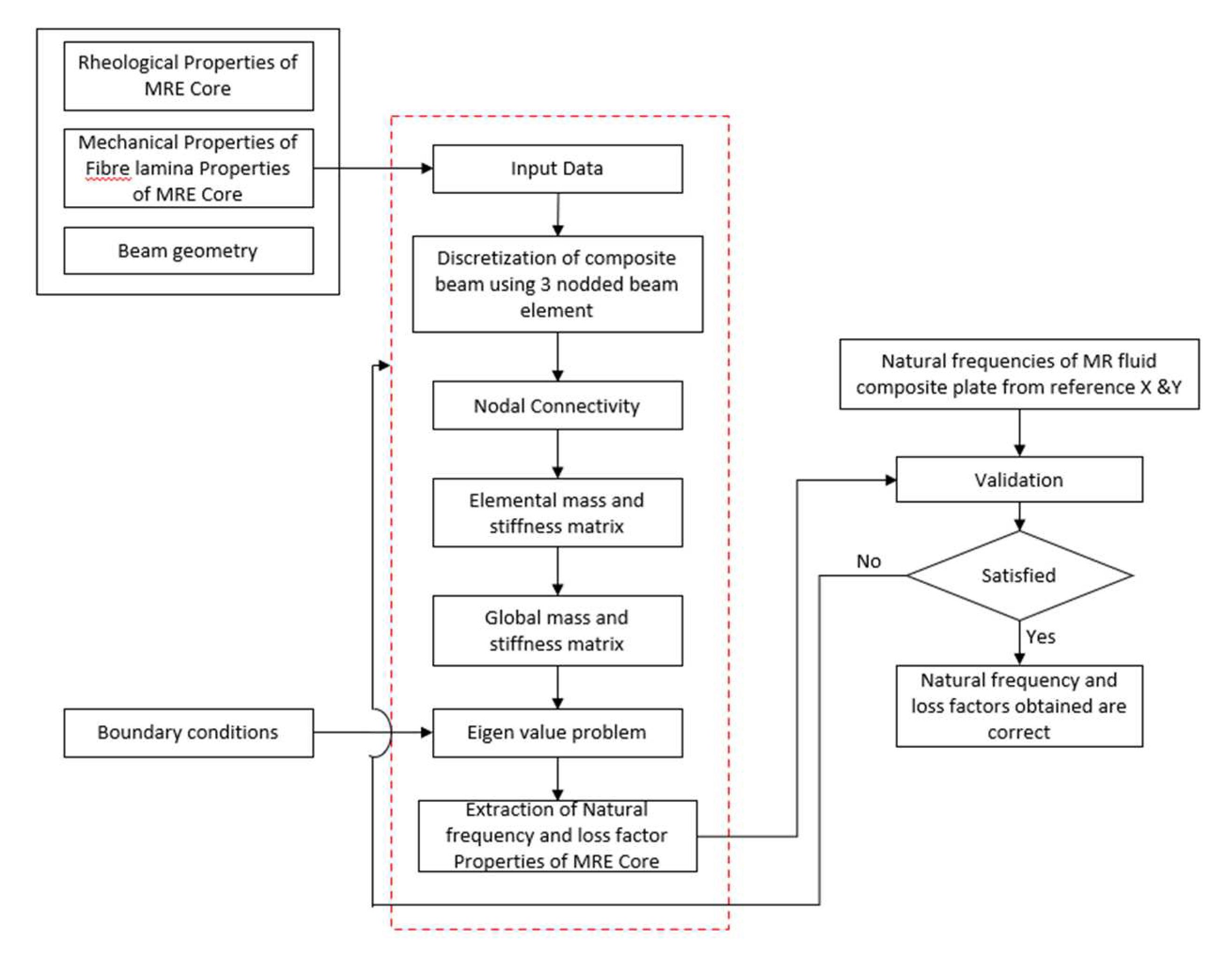
Previous research into hybrid matrix MREs has shown limited progress in comprehending their mechanical, rheological properties and dynamic behavior. There exists a clear absence of both mathematical approaches and experimental investigations in analyzing the dynamic behavior of hybrid MRE composites. In the present study, the dynamic characteristics of NR/PBR-based hybrid magnetorheological (MR) elastomer sandwich composite beams are investigated using numerical simulations. This investigation considers various compositions of NR and PBR to develop finite element equations for the sandwich composite beam. The potential energy and kinetic energy equations for the hybrid elastomer sandwich composite beam with FRP face sheets, employing Reddy’s third-order shear deformation theory, are derived. Remarkably, there is a lack of research on the dynamic study of hybrid MRE sandwich composite structures. To address this gap, the governing differential equations of motion for the hybrid MRE sandwich composite beam are established, considering various compositions of the NR/PBR matrix. These equations are presented using a three-node line element with five degrees of freedom at each node. To validate the finite element simulations, the results are compared with existing data on MR fluids available in the literature. Additionally, the study examines the dynamic characteristics of various configurations of hybrid MRE sandwich composite beams under the influence of magnetic field intensity, ply orientation, core thickness, and boundary conditions. Figure 1 outlines the various steps involved in the numerical simulation of hybrid MRE sandwich composites, representing a concerted effort to gain a deeper understanding of the characteristics of these structures.
2. Mathematical Modelling

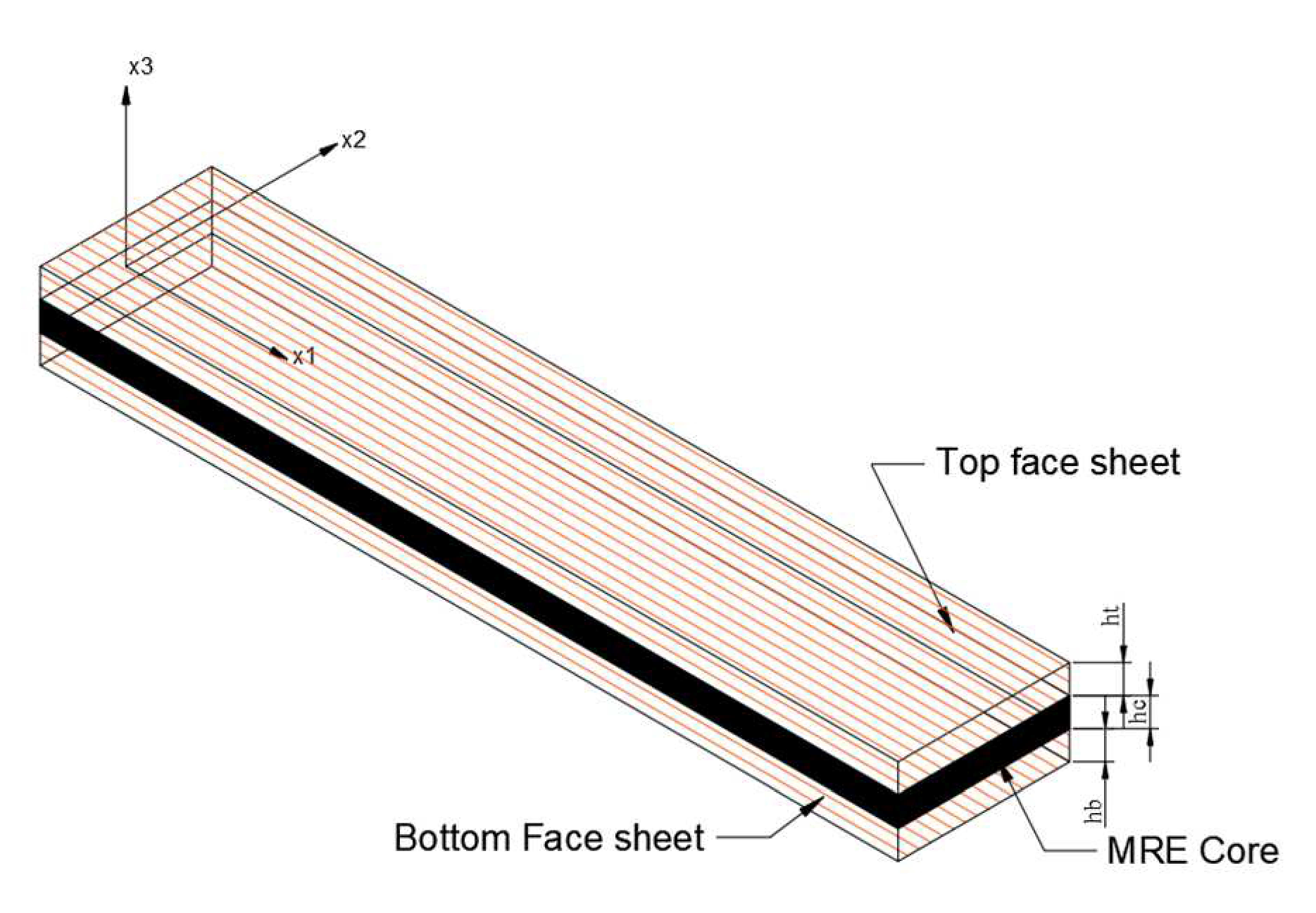
Sandwich composite structures with laminated face sheets, as shown in Figure 2, are used in various high-performance engineering applications, such as aircraft wings, windmill blades, and helicopter rotor blades, due to their exceptional structural characteristics. These composite structures consist of a core composed of Carbonyl iron Powder (CIP), a magnetic filler material uniformly dispersed in a hybrid MR elastomer core comprising both PBR (polybutadiene rubber) and NR (natural rubber). Flanking this core are multi-layered face sheets made of glass fiber-reinforced polymer. In the analysis, perfect bonding between all three layers of the sandwich composite beam is assumed. To comprehensively explore the dynamic properties of these composite beams, four distinct configurations of hybrid MR elastomers, denoted as SC1, SC2, SC3, and SC4, are considered. The composition of these hybrid elastomers is detailed in Table 1, where the proportions of PBR mixed with NR are determined following the approach outlined by Song et al. [26]. The geometric parameters of the sandwich composite beam include the length and width of the face sheets, represented as ‘L’ and ‘w’, respectively. Additionally, we define the thicknesses of the elastomer core, bottom face sheet, and top face sheet as ‘hc’, ‘hb’, and ‘ht’, respectively.

2.1. Modelling of face sheets

The governing differential equations of motion for the sandwich composite beam were formulated using Reddy’s third-order shear deformation theory (RTSDT). RTSDT incorporates shear deformation effects by assuming that the deformation field of the skin layers varies as a third order function of x 3 , representing the thickness coordinate of the sandwich composite beam. This theory provides a more accurate description of the displacement field for the face sheets of the sandwich composite beam, and its formulation is as follows:
u 1 j x 1 , x 3 , t = u 1 0 j x 1 , t + x 3 φ x 1 , t + x 3 2 θ x 1 , t + x 3 3 x 1 , t         j = t , b u 3 j x 1 , x 3 , t = u 3 0 j = u 3 0
The displacements along the x 1 axis for the first and third layers, as well as the transverse deflection along the x 3 direction, are denoted as u 1 j and u 3 j , respectively. It is assumed that the transverse deflection for the first and third layers is equal. Furthermore, considering that the bottom and top layers of the composite beam are traction-free, the boundary conditions can be expressed as follows:
τ x 1 x 3 j x 1 , ± h j 2 , t = 0
To account for the assumed traction-free boundary condition of the beam, we can simplify the displacement parameters by eliminating the second-order terms. Following this reduction, the resulting displacement field, which contains third-order terms, is given as follows:
u 1 j x 1 , x 3 , t = u 1 0 j x 1 , t + x 3 φ x 1 , t 4 x 3 3 3 h j 2 ζ ζ = u 3 0 j x 1 + φ
The transverse term about the x 1 axis is represented as φ , while the wrapping term ζ is expressed in terms of the transverse plane rotation. The strain-displacement relationship for the face sheets of the sandwich composite beam, derived using the small strain theory, is as follows:
ε x 1 j = ε 0 j + x 3 ε 1 j + x 3 3 ε 3 j , γ x 1 x 3 j = γ 0 j + x 3 2 γ 2 j
where,
ε 0 j = u 1 0 j x 1 , ε 1 j = φ x 1 , ε 3 j = k 1 ζ x 1 γ 0 j = ζ ,   γ 2 j = k 2 ζ
Where in,   k 1 = 4 / 3 h j 2 and k 2 = 3 k 1 . The resultant force and moments of the sandwich composite beam which are analogous with the strain terms given in equation 4 is represented as
N j = A B D ε j
where N j matrix includes bending moment, in-plane force, transverse shear and higher order shear force resultants, and higher order moments. A B D matrix contains terms of transverse shear stiffness, bending stiffness, extensional stiffness, extensional–bending stiffness, higher order transverse shear stiffness and extensional bending which are given in equation-(i) of appendix-I.

2.2. Modelling of MR Elastomer Core

In the modeling of Magnetorheological Elastomers (MREs), it is presumed that the normal stresses developed within the MR elastomer core are negligible due to its significantly lower elastic modulus compared to the face sheets. Additionally, a no-slip condition is assumed at the interface between the face sheets and the MR elastomer core, simplifying the boundary conditions. To facilitate the modeling process, the longitudinal deformation ( u 1 c ) and transverse shear strain ( γ c ) of the elastomer core are derived from the kinematics of the deformed elastomer, providing essential parameters for the construction of a comprehensive MRE model.
u 1 c = u 1 t u 1 b 2 + h b h t 4 φ + h b h t 12 ζ γ c = u 1 t u 1 b h c h t + h b 2 h c φ + h t + h b 6 h c ζ + u 3 0 x 1
The resultant shear force associated with MR elastomer core is expressed as
Q c = G x z ' h c γ c
where G x z ' is complex shear modulus of constraining layer which is expressed as
G x z ' = G * ( 1 + i ɳ )

2.3. Kinetic and Strain Energy Formulations

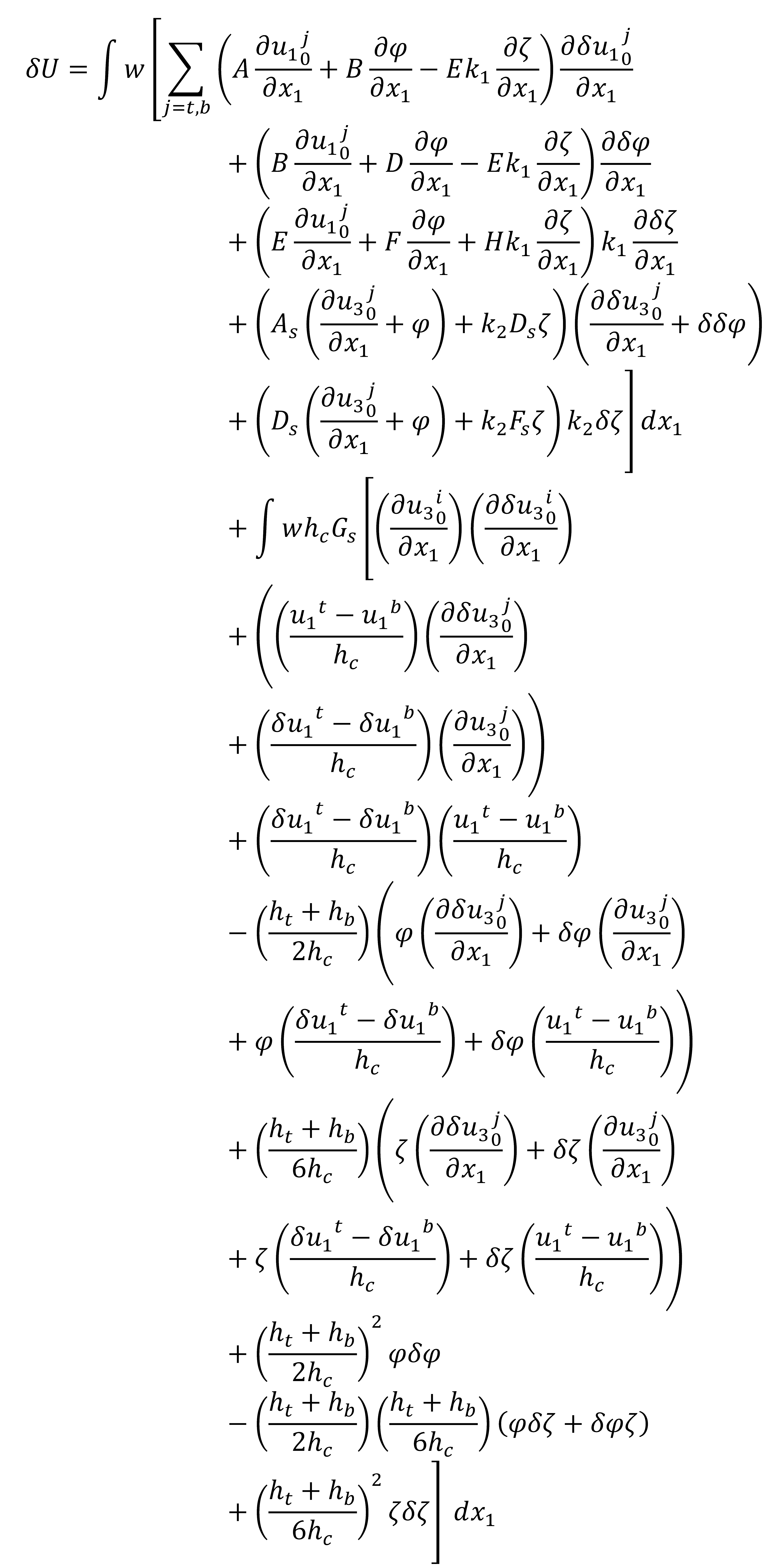
The strain energy ( δ U ) attributed to the virtual displacements in the NR/BR hybrid MR elastomer sandwich composite beam with face sheets can be expressed as follows:
δ U = w j = t , b N j δ ε 0 j + M j δ ε 1 j k 1 δ P j ε 3 i + Q j δ γ 0 j k 2 R j δ γ 2 j + R c δ γ c d x 1
Furthermore, the strain energy is reduced in relation to the deformation field as
Preprints 88184 i001
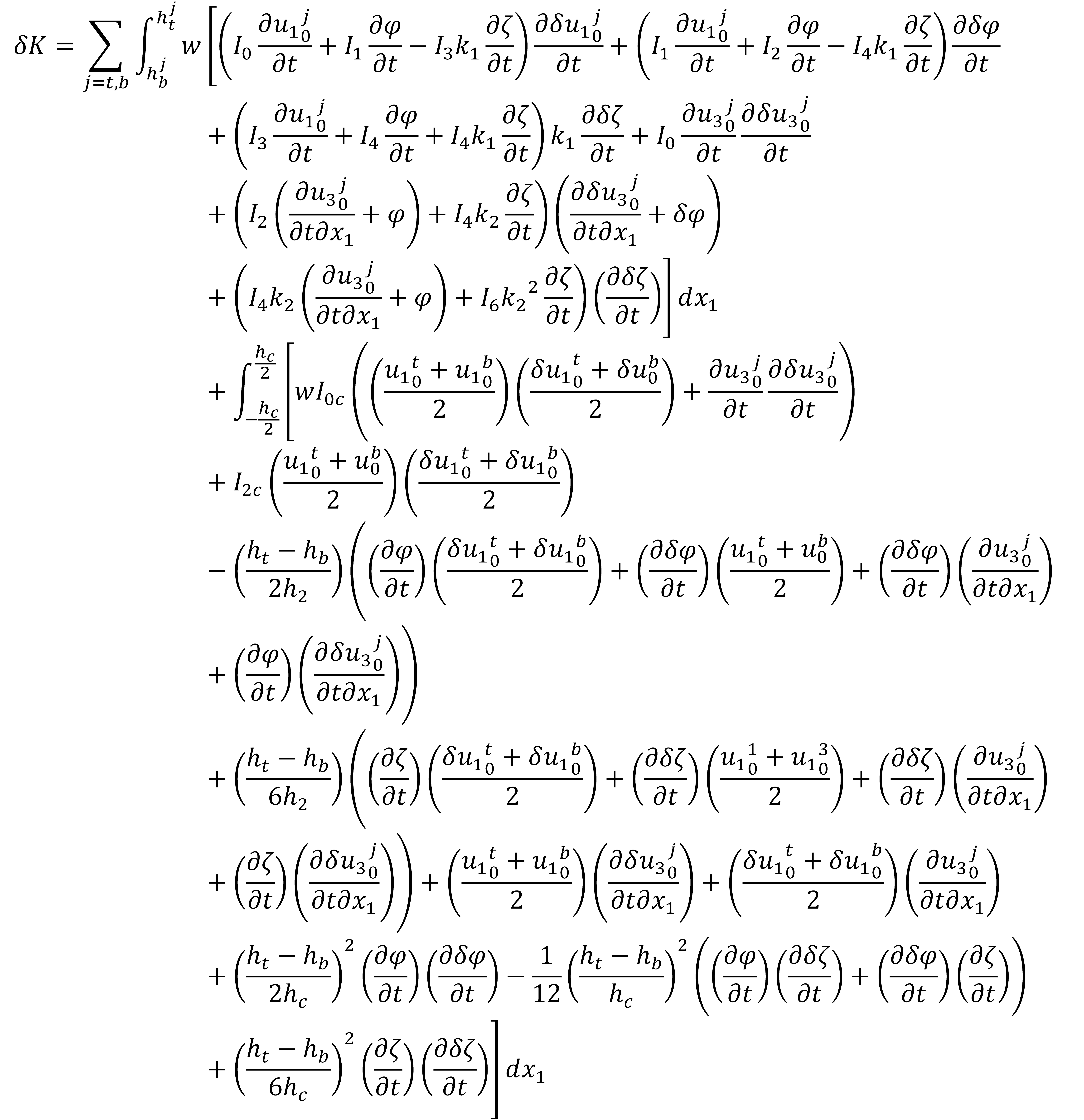
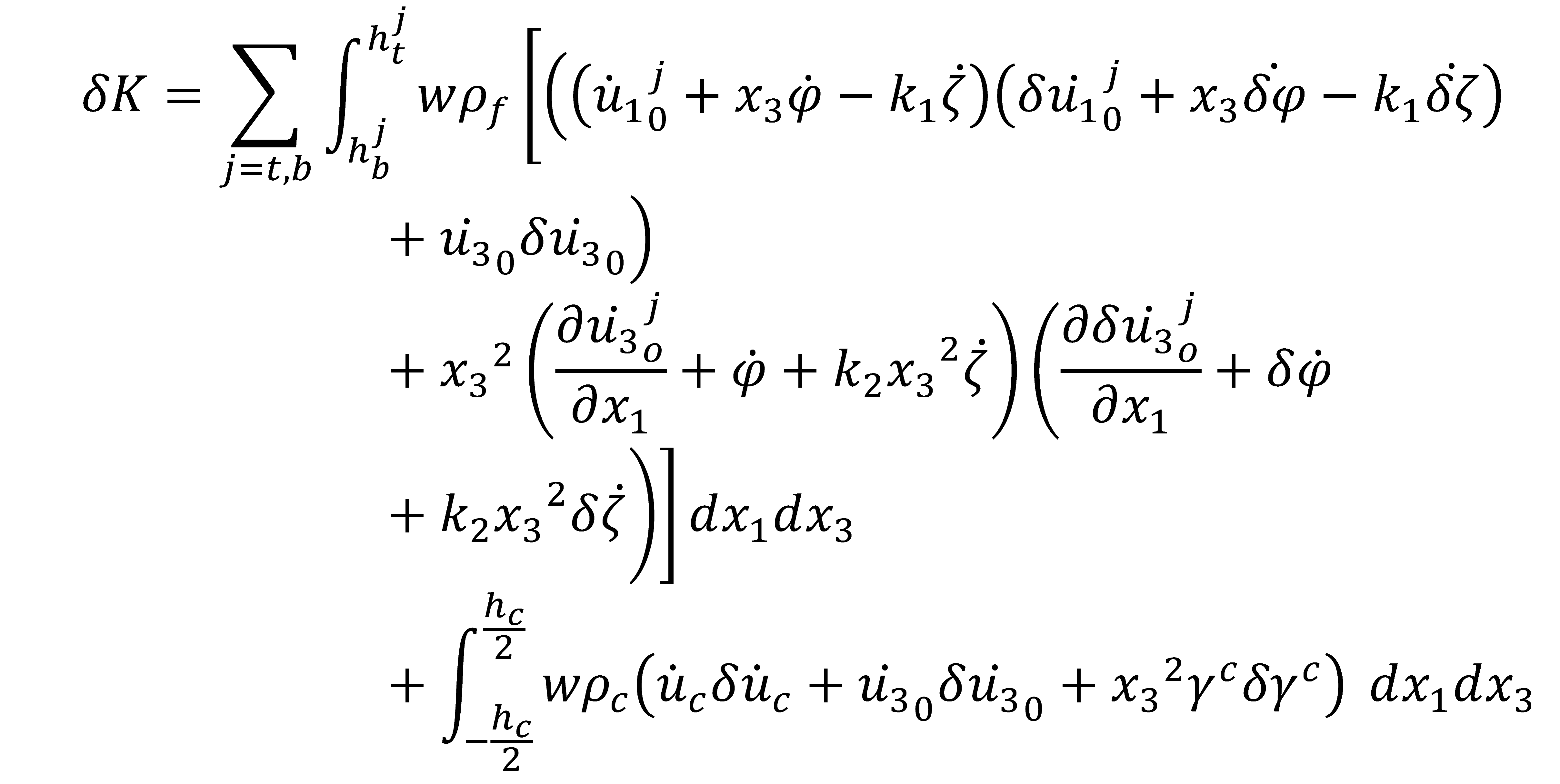
The kinetic energy ( δ K ) resulting from the in-plane, transverse, and shear displacements of the structure is expressed as follows:
Preprints 88184 i002
Further, the kinetic energy is reduced in the form of
Preprints 88184 i003
where I 0 ,   I 1 , I 2 , I 3 , I 4 , I 6 are inertia terms are given in equation-(ii) of appendix-I.
The expression for the virtual work done ( δ V ) due to the distributed transverse load q ( x , t ) at time t is as follows:
δ V = q δ u 3 0 d x 1
Let δ w 0 represent the virtual transverse deflection of the sandwich composite beam. When dealing with dynamic structures, it’s important to establish that admissible virtual displacements are set to zero at two specific instances, denoted as t 1 and t 2 , during which the precise position of the structure is known. To derive the variational functional, denoted as I, for the initial value problem, Hamilton’s principle is employed as
Preprints 88184 i004
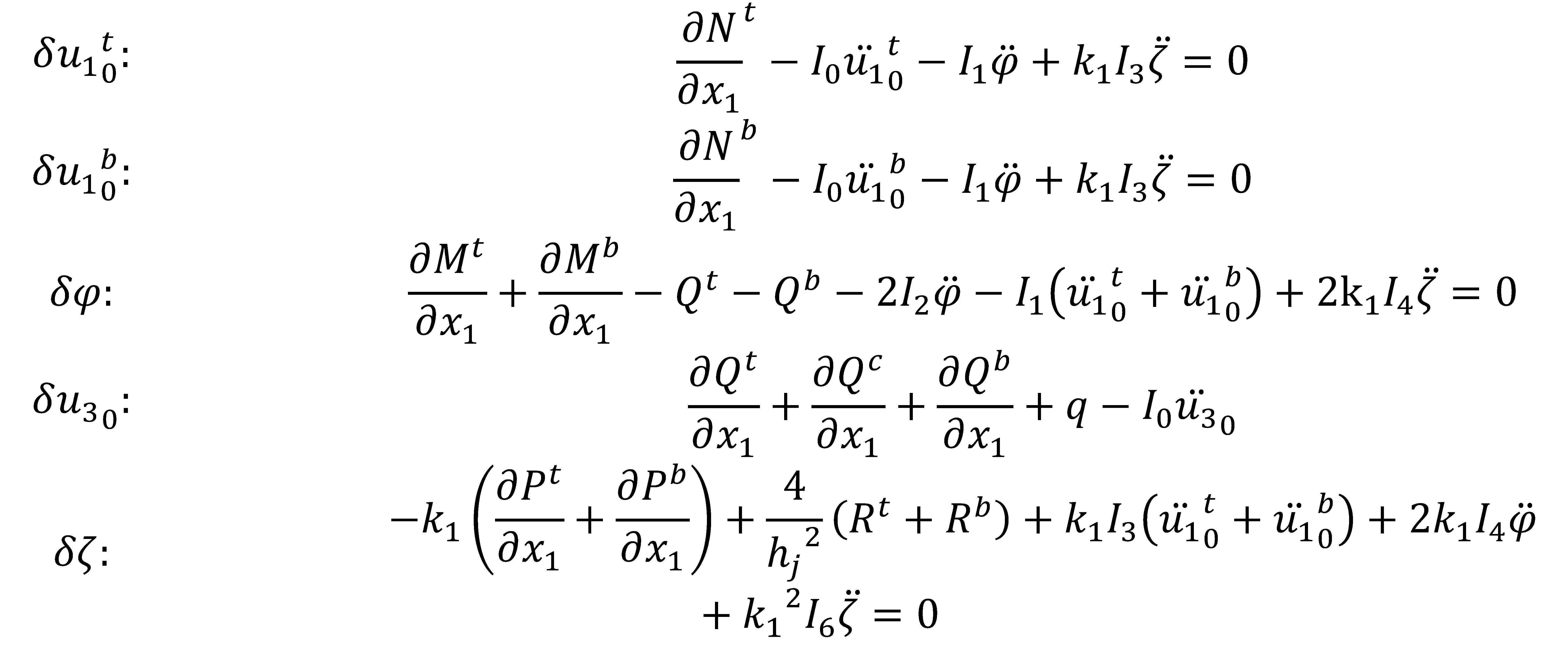
The governing differential equations of motion of the sandwich composite beam are attained by setting the coefficients of virtual displacements in the domain Ω to zero.
Preprints 88184 i005

2.4. Finite Element Formulations

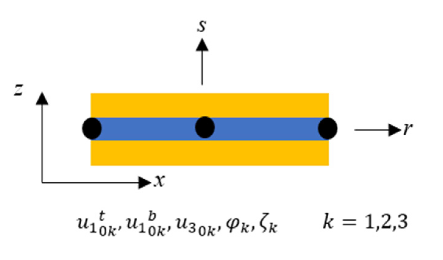
The sandwich composite beam, which consists of multiple layers of NR-BR hybrid Magnetorheological Elastomer (MRE) with face sheets, has been modelled using elements featuring three nodes, each with five degrees of freedom (DOF), as illustrated in Figure 3. This beam element model encompasses various parameters at each node, including axial deformations of the top ( u 1 0 t ), and bottom ( u 1 0 b ) face sheets, transverse deflection ( u 3 0 ) , transverse rotation ( φ ), and higher-order term ( ζ ). To represent the deformation field within this distinctive element of the sandwich composite beam, we utilize nodal DOF and Lagrange interpolation functions in natural coordinates as
u 1 0 t u 1 0 b u 3 0 φ ζ = N ^ k 0 0 0 0 0 N ^ k 0 0 0 0 0 0 0 0 0 N ^ k 0 0 0 N ^ k 0 0 0 N ^ k u 1 0 k t u 1 0 k b u 3 0 k φ k ζ k k = 1,2 , 3
Substituting eq (14) into variational principle, and expressing in terms of finite element equation the governing equations of motion are written as
M e d ¨ e + K * d e = f e
where d e , M e , f e , and K * denote element deformation vector, element mass matrix, element force vector and element stiffness matrix respectively. After the assembly of element mass matrix and stiffness matrix, the governing equations of motion for composite beam is given as
M q ¨ + K * q = f
d , M , f , and K * denote global deformation vector, mass matrix, force vector, and global complex stiffness matrix respectively. The force vector for free vibration is considered to be null thereby reducing the eq (17) as
M q + K * q = 0
The solution d for the eq. (19) can be expressed in terms of arbitrary constant ( C 1 ) as
q = [ C 1 ] e λ t
Eq. (21) reduces the eq. (20) into eigen value problem as
M λ K * C 1 = 0
where λ is the characteristic value which is obtained as
λ = λ j
The physical deformation vector can be determined using eq. (21) only after formulating the deformation vector q ( t ) from the eq. (20).
The natural frequency ( ω j ) and loss factor ( ɳ j ) at each mode are obtained using the eq. (23) as
ω j = R e ( λ j ) ɳ j = I m ( λ j ) R e ( λ j )

2.5. Validation of Established Finite Element Formulation

The validity of Finite element simulations is verified by comparing the natural frequencies of MR fluid sandwich beam with elastic face layers obtained from the available literature using developed MATLAB code. The geometrical and mechanical properties of sandwich composite are considered to be same as that of Rajmohan et al. [30]. Elastic layer length = 300 mm, breadth b= 30 mm, thickness he= 1 mm, elastic modulus Ee =68GPa, storage modulus Ge=26 GPa, density of elastic layer ρe = 2700 kg/m3, MR fluid core thickness hc= 1 mm, density of rubber ρr = 1233 kg/m3, density of MR fluid ρcf = 3500 kg/m3, shear modulus function of MR fluid G’= -3.3691G2+4.9975 x 10³G + 0.893 MPa, G’’= 0.9 G2+0.8124 x 10³G+0.1855 M Pa where G indicates the applied magnetic field intensity in Gauss. The simulations are performed to obtain first five natural frequencies of three-layer MR fluid sandwich composite at 0 G and 250 G magnetic field under simply supported boundary condition. The simulated natural frequencies are correlated with that of Rajmohan et al. [30] and Rajmohan et al. [31] as presented in the Table 2. The maximum deviation observed between the simulated frequencies with the frequencies presented by Rajmohan et al. [30] is 8% and with that of Rajmohan et al. [31] is 4%. The models used in Rajmohan et al. [30] and Rajmohan et al. [31] assume no warping of transverse normal during the deformation resulting in the deviations of the results. Therefore, the developed FE model based on Reddy third order shear deformation can be considered to be a better model in evaluating the dynamic characteristics of sandwich composite beam. Further, conclusion may be drawn, that the proposed model has good agreement with Rajmohan et al. [30] and Rajmohan et al. [31] in predicting the natural frequencies of three-layer MR fluid composite beam.
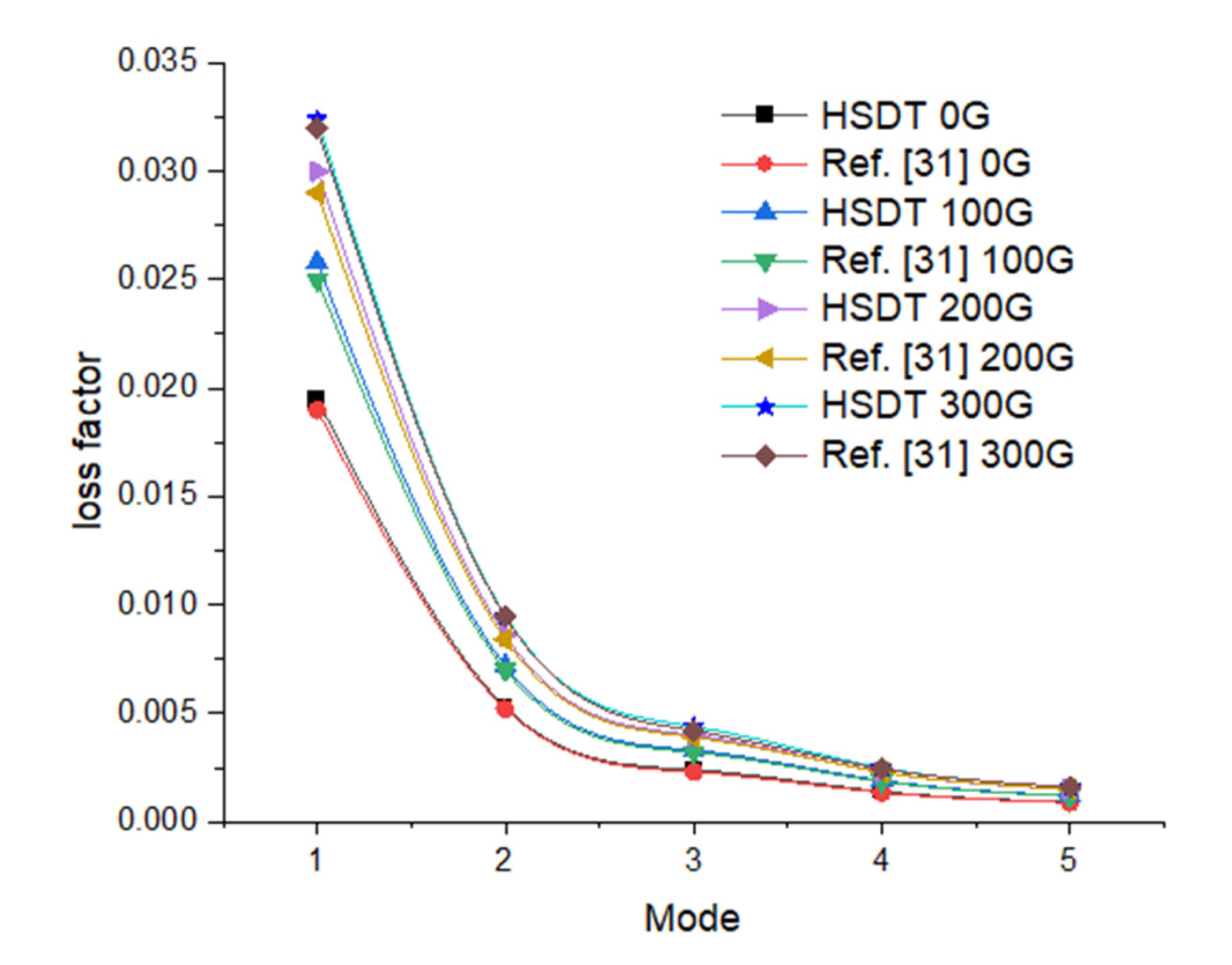
In addition to using finite element simulations for predicting and comprehending the dynamic behaviour of MR elastomer sandwich composite structures, the validation of the FEM approach is further substantiated by comparing the loss factor with data obtained by RajaMohan et al. [31] for MRE sandwich composite structures. This comprehensive validation underscores the accuracy of the finite element model in capturing intricate interactions and behaviours within such composite structures. By achieving strong alignment with prior research, the model instils confidence in its capability to predict and analyze the dynamic responses of similar MR elastomer sandwich composite structures.
Figure 4. Variation of loss factor of five modes under various magnetic field.
Preprints 88184 g004

3. Results

Finite element simulations are performed on hybrid MRE sandwich composite beam having dimensions 300 mm × 30 mm × 4 mm to evaluate loss factor and natural frequencies. The face sheet is assumed to be three-layer fibre reinforced polymer laminate with the layup sequence of [0°/90°/0°]s having 0.54 mm thickness. The hybrid elastomer thickness is considered to be 3 mm. The mechanical properties of face sheet [32]and rheological properties of hybrid elastomer [26] considered for the simulation are given in Table 3 and Table 4 respectively. Analysis was performed under varying magnetic field intensity from 0mT to 750mT and three different end conditions namely both ends clamped (CC), one end clamped and free at another end (CF) and simply supported at both ends (SS). The damping characteristics and natural frequencies of sandwich composite beam are highly influenced by matrix mixture (NR/PBR) content, magnetic field intensity, Ply orientation, thickness ratio and boundary conditions. The change in loss factor has a substantial effect on damping properties of composite beam. Therefore, it is essential to examine the influence of all these parameters on dynamic properties of sandwich composite beam.

3.1. Influence of applied magnetic field intensity on natural frequency and loss factor of sandwich composite beam

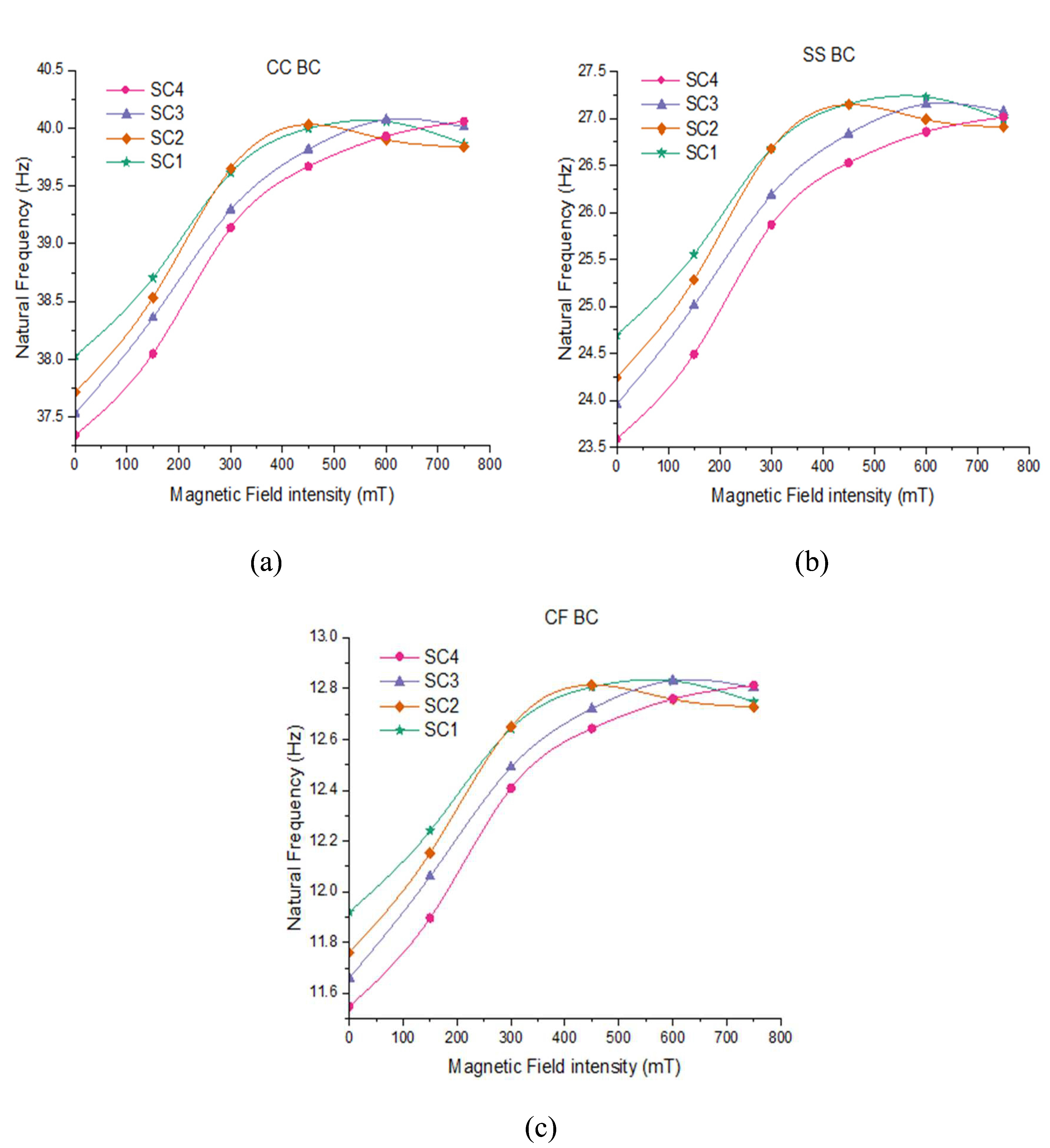
The investigation is conducted to examine the effect of applied magnetic field intensity on natural frequencies and loss factor of sandwich composite beam. The extracted fundamental natural frequencies of sandwich composite beams with various hybrid elastomer cores such as SC1, SC2, SC3 and SC4 are plotted for various magnetic field and boundary conditions as shown in Figure 5. It can be clearly seen from Figure 5 that at zero magnetic field the fundamental natural frequency increases by 3% under CF, 2% under CC and 4% under SS boundary conditions respectively, with increase in NR content from 0 to 90phr. The increment in natural frequencies of all the configurations could be due to improvement in stiffness of hybrid MR elastomer resulting from increased strain crystallization with the increase in NR content [26]. The maximum increase in the fundamental natural frequency of SC1, SC2, SC3 and SC4 based composite beams is found to be 7.6%, 8.5%, 10.1% 10.4% respectively at 600mT under CF boundary condition. The highest improvement in fundamental natural frequency is observed in SC4 based composite beam. This can be due to increased compatibility of CI particles with PBR which restricts the motion of rubber molecules resulting in improved field dependent modulus. Further, the first five natural frequencies of various sandwich composite beams for various magnetic field and boundary conditions are presented in Table 5. It can be seen that with applied magnetic field intensity the natural frequencies at all the modes tend to increase up-to 600mT and further it is observed that there is slight decrement at higher intensity of magnetic field. The cause of this decrement at higher magnetic strength can be ascribed to agglomeration of magnetic filler particles and breakdown of separated filler chains [33]. Also, the results indicate that CC and CF boundary conditions have highest and least natural frequencies respectively under all intensities of magnetic field. This can be attributed to the fact that the clamped ends provide higher stiffness to the beam when compared to free end.
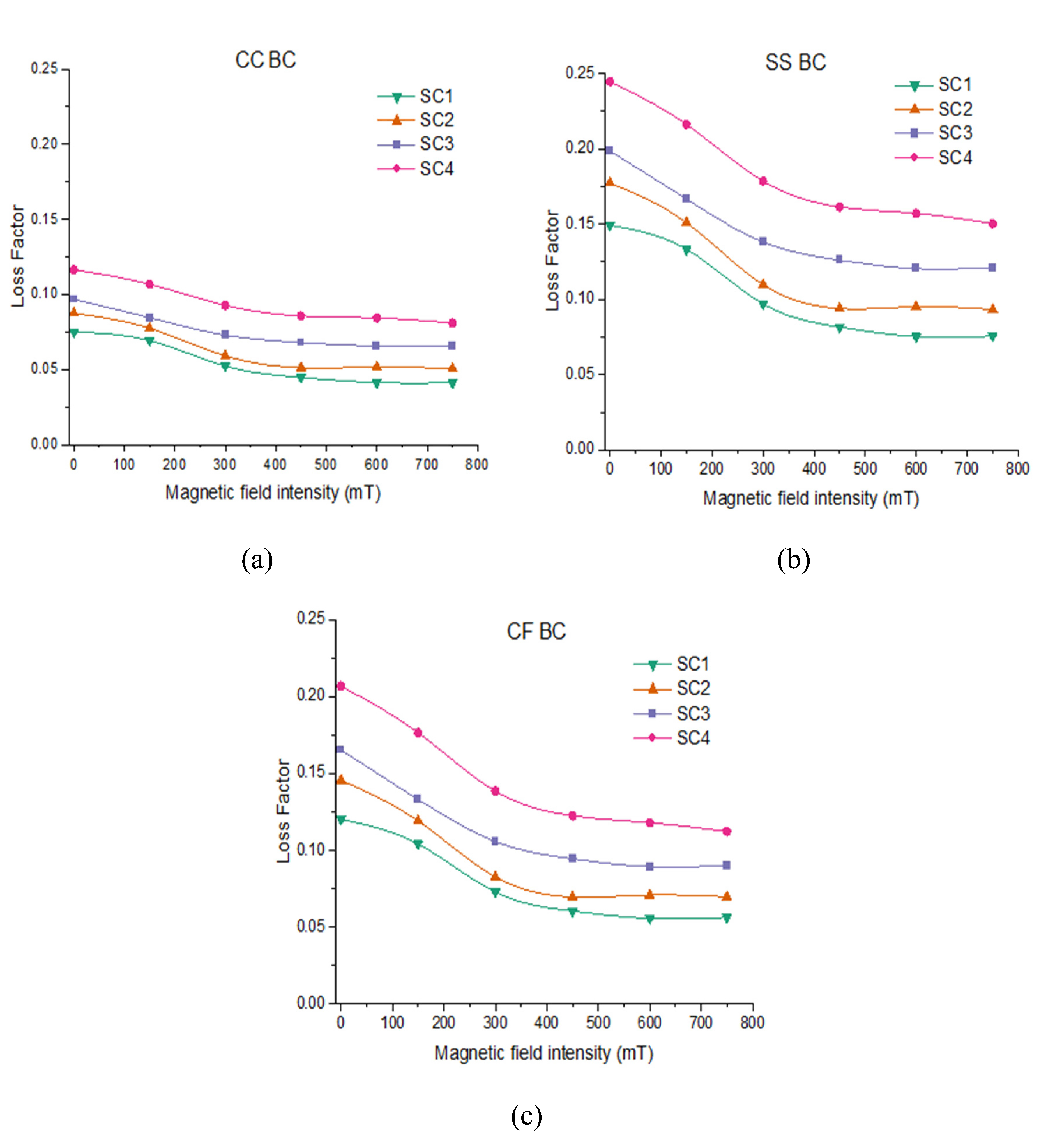
The loss factor at fundamental mode of various sandwich composite beams is plotted for various boundary conditions with intensity of magnetic field as shown in Figure 6. Referring to Figure 6, the improvement in loss factor increases from 66% to 136% with increase in magnetic field intensity from 0 to 600mT when PBR content increases from 10% to 100% under CF boundary condition. This increase in damping can be due to increased interfacial friction between hybrid matrix and CI particles resulting from intermolecular interaction as the PBR content is increased. Further, loss factor for SC1, SC2, SC3 and SC4 based composite beams is found to decrease by 54%, 50%, 44% and 43% respectively when magnetic field increases from 0mT to 600mT for CF boundary condition. Under the externally applied magnetic field the alignment of CI particles restricts the movement of hybrid rubber matrix molecules resulting in reduced energy dissipation thereby reducing the loss factor [34]. It can be observed that SS and CC boundary conditions have largest and lowest loss factor respectively under all magnetic field intensity.

3.2. Influence of MRE core thickness on natural frequencies and loss factor of sandwich composite beam

The effect of the MRE core thickness on the fundamental loss factor and natural frequency of sandwich composite beams is summarized in Table 6 and 7. It is evident that as the core thickness increases from 1.5mm to 4.5mm, the fundamental natural frequency of composite beams for SC1, SC2, SC3, and SC4 increases by approximately 16%, 15.5%, 14.8%, and 14.2%, respectively, under zero magnetic field conditions with clamped-free (CF) boundary conditions. This increase in natural frequency can be attributed to the greater stiffness of the beam resulting from the thicker core. Furthermore, Table 7 reveals that the loss factor for composite beams SC1, SC2, SC3, and SC4 increases by 75%, 78%, 80%, and 84%, respectively, at zero magnetic field under CF boundary conditions. This significant improvement in damping properties is likely due to the increased interfacial friction between the hybrid matrix and CI particles within the thicker core. These findings underscore the potential for optimizing the mechanical and damping properties of sandwich composite beams by carefully selecting and adjusting the thickness of the MRE core, offering valuable insights for engineering applications requiring vibration control and damping.

3.3. Influence of ply orientation natural frequency and on loss factor of sandwich composite beam

The study focuses on the damping characteristics and natural frequency of sandwich composite beam samples with three different ply orientations: [0°/90°/0°]s, [90°/0°/90°]s, and [0°/90°/45°]s, and their respective effects are summarized in Table 8 and Table 9. It is noteworthy that the fundamental natural frequency of all beam configurations at zero magnetic field, under clamped-free (CF) boundary conditions, follows the order of ply orientation: [90°/0°/90°]s, [0°/90°/45°]s, and [0°/90°/0°]s. Specifically, the natural frequency increases by 11% for [0°/90°/0°]s and 10% for [0°/90°/45°]s compared to [90°/0°/90°]s across all composite beam configurations. The lowest natural frequency is associated with the ply orientation [90°/0°/90°]s, signifying that the outermost face-sheet with a 90° orientation contributes to decreased beam stiffness. Furthermore, under zero magnetic field and CF boundary conditions, the loss factor for all beam configurations follows the order of ply orientation: [90°/0°/90°]s, [0°/90°/0°]s, and [0°/90°/45°]s. Notably, the loss factor increases by 1% for [0°/90°/0°]s and 15% for [0°/90°/45°]s compared to [90°/0°/90°]s across all composite beam configurations. While [0°/90°/45°]s exhibits a high loss factor, the natural frequency remains relatively lower due to the 45° ply introducing shear forces, which reduce beam stiffness. The increase in the loss factor can be attributed to heightened energy dissipation facilitated by the unrestricted motion of rubber molecules caused by the presence of carbonyl iron (CI) particles in the hybrid matrix. These results collectively demonstrate the intricate interplay between ply orientation, natural frequency, and loss factor, shedding light on the dynamic behavior of the sandwich composite beams.

3.4. Frequency response of hybrid MRE sandwich composite beam

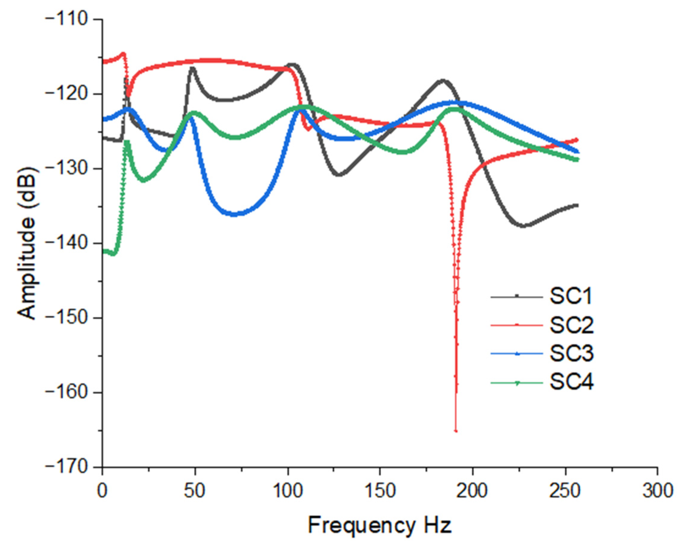
The investigation focused on the transverse vibration response of the hybrid MRE sandwich composite beam (SC1) under the constraint-free (CF) boundary condition, with varying magnetic field intensities. The responses were analyzed across a frequency range of 1-250 Hz by considering harmonic excitation force of magnitude 5 N at free end corner of the beam. Forced vibration simulation is performed on various, as depicted in Figure 7. In Figure 7, it is evident that there is a noticeable leftward shift in the natural frequency as the magnetic field intensity increases. This phenomenon can be attributed to appreciation in the stiffness with the rise in magnetic field strength. Additionally, it can be observed that the amplitude of vibration decreases with higher magnetic field intensities. Figure 8 presents the vibration responses of all configurations of composite beams at 450 mT. Due to variations in the stiffness of the beams, slight fluctuations in responses at certain modes can be observed. These results imply that the application of a magnetic field has a significant impact on the transverse vibration behavior of the hybrid MRE sandwich composite beam. As the magnetic field intensity increases, the natural frequencies shift to higher values, and the amplitudes of vibration decrease. This finding suggests the potential for precise control and tuning of the dynamic response of such composite structures, which is promising for various engineering applications where vibration control and damping are crucial.

4. Conclusions

The paper extensively investigates the dynamic characteristics of MR hybrid sandwich composite beams with various configurations. It utilizes differential equations based on the Reddy third-order shear deformation theory (RTSDT) to gain valuable insights into behavior of the structures. The study emphasizes the significant impact of magnetic field intensity and the ratio of PBR to NR on the natural frequency and loss factor of hybrid MR elastomer sandwich composite beams. Additionally, an exploration of factors such as ply orientation, boundary conditions, and elastomer core thickness provides a comprehensive understanding of these variables affecting the dynamic properties of the sandwich composite structure. The study observes that natural frequencies increase with magnetic field intensity up to 600 mT but decrease beyond that due to filler chain breakdown and particle agglomeration. Furthermore, an increase in PBR content notably improves damping properties, as evidenced by a significant increase in the loss factor. Similarly, an increase in NR content enhances stiffness, as seen in the rise of the fundamental natural frequency. Ply orientation is found to impact natural frequencies, with a significant 11% increase observed for the [0°/90°/0°]S orientation. Finally, an increase in elastomer core thickness contributes to higher natural frequencies and improved damping. This research provides practical guidance for engineering applications, enabling the optimization of hybrid MR elastomer sandwich composite beams for various structural purposes. By tailoring factors such as magnetic field intensity, composition, and structural configurations, these materials can effectively enhance the performance, safety, and longevity of various structural systems and equipment.

Author Contributions

Conceptualization, Lakshmi Pathi J; Data curation, Mohanraj T; Formal analysis, Ahobal N and Lakshmi Pathi J; Investigation, Ahobal N and Lakshmi Pathi J; Project administration, Sakthivel G and Yogesh Bhalerao; Resources, Mohanraj T; Software, Jegadeeshwaran R; Supervision, Sakthivel G and Yogesh Bhalerao; Validation, Jegadeeshwaran R; Writing – original draft, Lakshmi Pathi J; Writing – review & editing, Jegadeeshwaran R.

Funding

The authors declare no funding details.

Data Availability

The data used to support the findings of this study are included within the article.

Acknowledgments

The authors thank the Management of Vellore Institute of Technology, VIT Chennai and Amrita School of Engineering, Coimbatore, Amrita Vishwa Vidyapeetham, India, and for their support to publish this work.

Conflicts of Interest

“The authors declared no conflict of interest”.

Appendix-I

From equation 6 we have N j = A B D ε j
where, N j = N j M j P j Q j R j , A B D = A B E 0 0 B D F 0 0 E F H 0 0 0 0 0 A s D s 0 0 0 D s F s , ε j = ε 0 j ε 1 j ε 3 j γ 0 j γ 2 j
Therefore, N j = A B D ε j is given as
N j M j P j Q j R j =   A B E 0 0   B D F 0 0   E F H 0 0   0 0 0 A s D s   0 0 0 D s F s   ε 0 j ε 1 j ε 3 j γ 0 j γ 2 j (i)
I 0 ,   I 1 , I 2 , I 3 , I 4 , I 6 = j = 1 n h j h j + 1 ρ 1 , x 3 , x 3 2 , x 3 3 , x 3 4 , x 3 6 d x 3   (ii)

References

  1. Bica, I.; Liu, Y.D.; Choi, H.J. Physical characteristics of magnetorheological suspensions and their applications. J. Ind Eng Chem. 2013, 19, 394–406. [Google Scholar] [CrossRef]
  2. Ashtiani, M.; Hashemabadi, S.; Ghaffari, A. A review on the magnetorheological fluid preparation and stabilization. J. Magn. Magn Mater. 2015, 374, 716–730. [Google Scholar] [CrossRef]
  3. Carlson, J.D.; Jolly, M.R. MR fluid, foam and elastomer devices. Mechatronics 2000, 10, 555–569. [Google Scholar] [CrossRef]
  4. Jolly M., R.; Carlson J., D.; Munoz B., C. A model of the behavior of magnetorheological materials. Smart Mater. Struct. 1996, 5, 607. [Google Scholar] [CrossRef]
  5. Khimi, S.R.; Pickering, K. The effect of silane coupling agent on the dynamic mechanical properties of iron sand/natural rubber magnetorheological elastomers. Compos. B. Eng. 2016, 90, 115–125. [Google Scholar] [CrossRef]
  6. Park, B.O.; Park, B.J.; Hato, M.J.; Choi, H.J. Soft magnetic carbonyl iron microsphere dispersed in grease and its rheological characteristics under magnetic field. Colloid Polym. Sci. 2011, 289, 381–386. [Google Scholar] [CrossRef]
  7. Guo, F.; Du, C.-b; and Li, R.-p. Viscoelastic parameter model of magnetorheological elastomers based on Abel dashpot. Adv. Mech. Eng. 2014, 6, 629386. [Google Scholar] [CrossRef]
  8. Deng, H.-X.; Gong, X.-l. Application of magnetorheological elastomer to vibration absorber. Commun Nonlinear Sci Numer Simul. 2008, 13, 1938–1947. [Google Scholar] [CrossRef]
  9. Chen, L.; Gong, X.L.; Li, W.H. Damping of magnetorheological elastomers. Chinese J. Chem. Phys. 2008, 6, 581–5. [Google Scholar] [CrossRef]
  10. Boczkowska, A.; Awietjan, S.F.; Pietrzko., S.; Kurzydłowski, K.J. Mechanical properties of magnetorheological elastomers under shear deformation. Compos. B. Eng. 2012, 2, 636–40. [Google Scholar] [CrossRef]
  11. Deng, H.X.; Gong, X.L.; Wang, L.H. Development of an adaptive tuned vibration absorber with magnetorheological elastomer. Smart Mater. Struct. 2006, 5, N111. [Google Scholar] [CrossRef]
  12. Jung, H.S.; Kwon, S.H.; Choi, H.J.; Jung, J.H.; Kim Y., G. Magnetic carbonyl iron/natural rubber composite elastomer and its magnetorheology. Compos Struct. 2016, 136, 106–112. [Google Scholar] [CrossRef]
  13. Gong, X.; Zhang, X.; Zhang, P. Fabrication and characterization of isotropic magnetorheological elastomers. Polym. Test. 2005, 24, 669–676. [Google Scholar] [CrossRef]
  14. Chen, L.; Gong, X.-l.; Jiang, W.-q.; Yao, J.-j.; Deng, H.-x.; Li, W.-h. Investigation on magnetorheological elastomers based on natural rubber. J. Mater. Sci. 2007, 42, 5483–5489. [Google Scholar] [CrossRef]
  15. Hafeez, A.M.; Usman, M.; Umer, M.A.; Hanif, A. ; Recent Progress in Isotropic Magnetorheological Elastomers and Their Properties: A Review. Polymers, 2020, 12, 3023–34. [Google Scholar] [CrossRef] [PubMed]
  16. Fan, Y.C.; Gong, X.L.; Jiang, W.Q.; Zhang, W.; Wei, B.; Li, W.H. Effect of maleic anhydride on the damping property of magnetorheological elastomers, Smart Mater. Struct. 2010, 19, 055015. [Google Scholar]
  17. Burgaz, E.; Goksuzoglu, M. Effects of magnetic particles and carbon black on structure and properties of magnetorheological elastomers, Polym. Test. 2020, 81, 106233–12. [Google Scholar]
  18. Pickering, K.L.; Khimi, S.R.; Ilanko, S. The effect of silane coupling agent on iron sand for use in magnetorheological elastomers Part 1: surface chemical modification and characterization. Compos A Appl. 2015, 68, 377–386. [Google Scholar] [CrossRef]
  19. Poojary, U.R.; Hegde, S.; Gangadharan, K.V. Experimental investigation on the effect of carbon nanotube additive on the field-induced viscoelastic properties of magnetorheological elastomer. J. Mater. Sci. 2018, 53, 4229–4241. [Google Scholar] [CrossRef]
  20. Khimi, S.R.; Pickering, K.L. The effect of silane coupling agent on the dynamic mechanical properties of iron sand/natural rubber magnetorheological elastomers. Compos. B Eng. 2016, 90, 115–125. [Google Scholar] [CrossRef]
  21. Bokobza, L. Elastomer Nanocomposites: Effect of Filler–Matrix and Filler–Filler Interactions. Polymers 2023, 15, 2900–22. [Google Scholar] [CrossRef]
  22. Zaman, I.; Manshoor, B.; Khalid, A.; Araby, S. From clay to graphene for polymer nanocomposites—a survey. J Polym Res. 2014, 21, 429–11. [Google Scholar] [CrossRef]
  23. Jovanović, S.; Samaržija-Jovanović, S.; Marković, G.; Jovanović, V.; Adamović, T.; Marinović-Cincović, M. Ternary NR/BR/SBR rubber blend nanocomposites. J. Thermoplast. Compos. Mater. 2018, 31, 265–287. [Google Scholar] [CrossRef]
  24. Abdelsalam A, Araby S, El-Sabbagh S; et al. Effect of carbon black loading on mechanical and rheological properties of natural rubber/styrene-butadiene rubber/nitrile butadiene rubber blends. J Thermoplast Compos. [CrossRef]
  25. Zhang, W.; Gong, X.; Xuan, S.; Jiang, W. Temperature-dependent mechanical properties and model of magnetorheological elastomers. Ind Eng Chem Res. 2011, 50, 6704–6712. [Google Scholar] [CrossRef]
  26. Song, X.; Wang, W.; Yang, F.; Wang, G.; Rui, X. The study of natural rubber/polybutadiene rubber hybrid matrix-based magnetorheological elastomer. J. Thermoplast. Compos. Mater. 2022, 35, 17–35. [Google Scholar] [CrossRef]
  27. El-Sabbagh, S.; Yehia, A. Detection of crosslink density by different methods for natural rubber blended with SBR and NBR. Egypt J Solids. 2007, 30, 157–173. [Google Scholar]
  28. Pal, K.; Rajasekar, R.; Kang, D.; Zhang, Z.; Pal, S.; Das, C.; Kim, J. Effect of Filler and Urethane Rubber on NR/BR with Nanosilica: Morphology and Wear. J. Thermoplast. Compos. Mater. 2010, 23. [Google Scholar] [CrossRef]
  29. Ge, L.; Gong, X.; Fan, Y.; Xuan, S. Preparation and mechanical properties of the magnetorheological elastomer based on natural rubber/rosin glycerin hybrid matrix. Smart Mater. Struct. 2013, 11, 115029. [Google Scholar] [CrossRef]
  30. Rajamohan, V.; Sedaghati, R.; Rakheja, S. Vibration analysis of a multi-layer beam containing magnetorheological fluid. Smart Mater. Struct. 2009, 19, 015013. [Google Scholar] [CrossRef]
  31. Rajamohan, V.; Sundararaman, V.; Govindarajan, B. Finite element vibration analysis of a magnetorheological fluid sandwich beam. Procedia Eng. 2013, 64, 603–612. [Google Scholar] [CrossRef]
  32. Edwin Sudhagar, P., Ananda Babu, A., Vasudevan, R., and Jeyaraj, P. Vibration analysis of a tapered laminated thick composite plate with ply drop-offs. Arch. Appl. Mech. 2015, 85, 969-990. 2015; 85, 969–990.
  33. Lee, J.Y.; Kumar, V.; Lee, D.-J. Compressive properties of magnetorheological elastomer with different magnetic fields and types of filler. Polym. Adv. Technol. 2019, 30, 1106–1115. [Google Scholar] [CrossRef]
  34. Fan, Y.; Gong, X.; Xuan, S.; Zhang, W.; Zheng, J.; Jiang, W. Interfacial friction damping properties in magnetorheological elastomers. Smart Mater. Struct. 2011, 20, 035007. [Google Scholar] [CrossRef]
Figure 1. Steps involved in numerical investigation.
Preprints 88184 g001
Figure 2. Dimensions of Sandwich composite beam.
Preprints 88184 g002
Figure 3. Three-noded beam element.
Preprints 88184 g003
Figure 5. Influence of intensity of magnetic field on natural frequencies of sandwich beam under (a) CC boundary condition; (b) SS boundary condition; (c) CF boundary condition.
Preprints 88184 g005
Figure 6. Influence of intensity of magnetic field on Loss factor of sandwich beam under (a) CC boundary condition; (b) SS boundary condition; (c) CF boundary condition.
Preprints 88184 g006
Figure 7. Transverse vibration response of hybrid MRE sandwich composite beam (SC1) under CF boundary condition.
Preprints 88184 g007
Figure 8. FRF plot of all configurations of hybrid MRE sandwich composite beam.
Preprints 88184 g008
Table 1. Composition of MR Elastomer core samples.
Materials SC1 SC2 SC3 SC4
PBR 10 30 50 100
NR 90 70 50 0
Carbonyl Iron (CIP) 190 190 190 190
Cumarone 12 12 12 12
ZnO 5 5 5 5
4010NA 2 2 2 2
RD 3 3 3 3
Sulphur 3 3 3 3
SA 1 1 1 1
CZ 0.5 0.5 0.5 0.5
PBR: polybutadiene rubber; NR: natural rubber; CZ: n-cyclohexyl-2 benzothiazole sulfonamide; RD: poly(1, 2-dihydro-2, 2, 4-trimethyl-quinoline); ZnO: zinc oxide; SA: stearic acid .
Table 2. Comparison of natural frequencies of sandwich beam determined from present FEM with that reported in [30,31].
Magnetic field in Gauss Modes Natural Frequencies (Hz)
Present FEM Ref [30] Ref [31] Error % [30] Error % [31]
1 38.84 40.34 40.74 3.71839 4.66372
2 105.45 103.1 105.7 2.27934 0.23652
0 3 210.93 200.07 206.51 5.4281 2.14033
4 356.45 332.45 344.72 7.21913 3.40276
5 542.6 501.67 521.57 8.15875 4.03206
1 51.57 50.92 51.88 1.27651 0.59753
2 125.2 120.32 123.56 4.05585 1.32729
250 3 235.47 222.24 229.01 5.95302 2.82084
4 383.33 357.33 369.67 7.27619 3.69519
5 570.92 528.15 547.94 8.09808 4.19389
Table 3. Rheological properties of hybrid MRE samples under various magnetic field.
Rheological properties Magnetic field in mT Hybrid MRE
SC1 SC2 SC3 SC4
G’(MPa) 0 0.48 0.45 0.43 0.4
150 0.53 0.51 0.49 0.45
300 0.6 0.595 0.56 0.53
450 0.63 0.625 0.6 0.57
600 0.635 0.615 0.62 0.59
750 0.62 0.61 0.615 0.6
ɳ 0 0.104 0.118 0.128 0.15
150 0.1 0.11 0.118 0.144
300 0.08 0.09 0.108 0.134
450 0.07 0.08 0.104 0.128
600 0.065 0.08 0.102 0.128
750 0.064 0.078 0.102 0.124
Table 4. Properties of fiber lamina and density of MRE core of various samples.
Lamina properties Density of MRE samples
E1 = 30.5GPa
E2 = 6.99Gpa ρSC1 = 2135.569 kg/m3
ν12= 0.269 ρSC2 = 2119.201 kg/m3
G12 = 2.8Gpa ρSC3 = 2103.081 kg/m3
G13 = G12 ρSC4 = 2063.836 kg/m3
G23 = 2.51Gpa
ρ= 1745 kg/m3
Table 5. First five natural frequencies (Hz) of samples under various boundary conditions.
MRE Samples BC Modes Magnetic field intensity
0mT 150mT 300mT 450mT 600mT 750mT
SC1 CF 1 11.91927 12.23997 12.64273 12.80502 12.82992 12.74658
2 45.01107 46.00776 47.30127 47.83229 47.91597 47.64571
3 101.103 102.6293 104.6851 105.5459 105.6853 105.2511
4 181.2576 182.9202 185.1959 186.1578 186.3154 185.832
5 287.6339 289.3705 291.7678 292.7863 292.9542 292.4434
CC 1 38.03013 38.70405 39.61301 39.99392 40.05566 39.8636
2 94.71789 95.76178 97.18789 97.79 97.88851 97.58583
3 176.3394 177.5886 179.3127 180.0451 180.1658 179.7985
4 283.5065 284.8658 286.7509 287.5541 287.687 287.2846
5 416.3424 417.772 419.7603 420.6089 420.7497 420.3247
SS 1 24.69532 25.54928 26.68158 27.15184 27.22716 26.98907
2 67.63693 68.88882 70.58256 71.29368 71.4092 71.05091
3 135.555 137.0116 139.0114 139.8581 139.9972 139.572
4 229.2759 230.8229 232.962 233.8717 234.0219 233.5658
5 348.9798 350.5754 352.7908 353.7352 353.8916 353.4186
SC2 CF 1 11.75898 12.15231 12.65093 12.81342 12.75771 12.72833
2 44.52597 45.74274 47.33647 47.86851 47.68779 47.59405
3 100.4284 102.28 104.7992 105.6623 105.3719 105.2239
4 180.6903 182.7003 185.4814 186.4458 186.1226 185.9592
5 287.2749 289.3705 292.2959 293.3171 292.9755 292.8036
CC 1 37.71648 38.53371 39.64736 40.02929 39.90083 39.83541
2 94.31609 95.57862 97.32214 97.92584 97.72343 97.62098
3 176.0078 177.5151 179.6192 180.3535 180.1079 179.9842
4 283.3637 285.0022 287.3008 288.106 287.837 287.7019
5 416.4742 418.1965 420.6196 421.4703 421.1863 421.0438
SS 1 24.24428 25.28294 26.6736 27.14497 26.98575 26.904
2 67.04697 68.56414 70.63811 71.35109 71.11147 70.98963
3 135.0022 136.762 139.2047 140.0537 139.7694 139.6258
4 228.8914 230.7574 233.367 234.2791 233.9742 233.8208
5 348.8513 350.7743 353.475 354.4219 354.1056 353.9468
SC3 CF 1 11.65949 12.05975 12.48997 12.72023 12.83099 12.80317
2 44.23157 45.46578 46.82328 47.56404 47.92454 47.83414
3 100.0493 101.918 104.0327 105.2122 105.7935 105.648
4 180.4456 182.4686 184.7872 186.0933 186.7409 186.5789
5 287.2523 289.3583 291.7882 293.1644 293.8489 293.6777
CC 1 37.53344 38.35807 39.29232 39.81385 40.07105 40.00666
2 94.11703 95.38822 96.84298 97.66154 98.06707 97.9656
3 175.9186 177.4335 179.1813 180.1711 180.6634 180.5402
4 283.4835 285.1288 287.0342 288.1165 288.6557 288.5208
5 416.8804 418.6089 420.615 421.7565 422.3259 422.1835
SS 1 23.95817 25.00864 26.18315 26.83226 27.15054 27.0708
2 66.70005 68.23012 69.96768 70.93952 71.41935 71.29923
3 134.7329 136.5032 138.537 139.6849 140.2546 140.1121
4 228.8072 230.6819 232.8479 234.076 234.6872 234.5343
5 349.0311 350.9617 353.1993 354.4711 355.1051 354.9465
SC4 CF 1 11.54746 11.89634 12.40732 12.6425 12.75894 12.81197
2 43.90747 44.97459 46.57497 47.32921 47.70346 47.87907
3 99.71048 101.3052 103.7732 104.9695 105.5649 105.8531
4 180.485 182.1989 184.8887 186.2093 186.8678 187.1909
5 287.8643 289.6414 292.451 293.84 294.5333 294.8759
CC 1 37.3451 38.04833 39.1381 39.66698 39.93023 40.0578
2 94.03016 95.10808 96.79713 97.6252 98.03797 98.24016
3 176.1791 177.4576 179.4787 180.4778 180.9764 181.2228
4 284.3001 285.6855 287.8844 288.9756 289.5205 289.7908
5 418.4291 419.8824 422.1949 423.345 423.9196 424.2053
SS 1 23.59108 24.4924 25.86879 26.52818 26.85595 27.01257
2 66.33237 67.63541 69.65979 70.64462 71.13501 71.37328
3 134.6308 136.1285 138.4853 139.6453 140.2239 140.5084
4 229.194 230.7747 233.2775 234.5165 235.135 235.4411
5 350.0858 351.7104 354.2917 355.5737 356.214 356.5319
Table 6. Variation of fundamental natural frequency (Hz) of MRE samples with core thickness.
MRE samples Core Thickness in mm Magnetic field intensity
0mT 150mT 300mT 450mT 600mT 750mT
SC1 1.5 10.6914 10.8794 11.10873 11.19967 11.21329 11.16621
3 11.91927 12.23997 12.64273 12.80502 12.82992 12.74658
4.5 12.44153 12.83503 13.33595 13.53934 13.5709 13.46684
SC2 1.5 10.60031 10.83163 11.11646 11.20739 11.17595 11.15912
3 11.75898 12.15231 12.65093 12.81342 12.75771 12.72833
4.5 12.2431 12.72488 13.34401 13.5478 13.4782 13.44174
SC3 1.5 10.5446 10.78049 11.02885 11.15951 11.22172 11.20608
3 11.65949 12.05975 12.48997 12.72023 12.83099 12.80317
4.5 12.11953 12.6092 13.14075 13.42756 13.56618 13.53139
SC4 1.5 10.48757 10.69432 10.99049 11.12393 11.1899 11.21911
3 11.54746 11.89634 12.40732 12.6425 12.75894 12.81197
4.5 11.97644 12.40191 13.0317 13.32452 13.46963 13.53654
Table 7. Variation of loss factor of MRE samples with core thickness.
MRE samples Core Thickness in mm Magnetic field intensity
0mT 150mT 300mT 450mT 600mT 750mT
SC1 1.5 0.080276 0.068653 0.047367 0.039047 0.035921 0.036456
3 0.12041 0.10418 0.07294 0.0605 0.05571 0.05635
4.5 0.140402 0.122066 0.085988 0.071504 0.065862 0.066524
SC2 1.5 0.097727 0.078866 0.053746 0.045009 0.045928 0.045254
3 0.145748 0.119227 0.082726 0.069694 0.070963 0.069839
4.5 0.169567 0.139482 0.097502 0.082351 0.083772 0.0824
SC3 1.5 0.111208 0.088485 0.069208 0.061286 0.057731 0.058316
3 0.165264 0.133245 0.105829 0.094524 0.089416 0.090226
4.5 0.192022 0.15564 0.1244 0.111516 0.105678 0.106586
SC4 1.5 0.139705 0.117939 0.091056 0.079836 0.076545 0.072718
3 0.206857 0.176515 0.138642 0.122572 0.118034 0.112333
4.5 0.240098 0.205741 0.162717 0.144349 0.139262 0.132634
Table 8. Effect of ply orientation on fundamental natural frequency of sandwich composite beam.
Magnetic field intensity mT [0°/90°/0°]s [90°/0°/90°]s [0°/90°/45°]s
SC1 SC2 SC3 SC4 SC1 SC2 SC3 SC4 SC1 SC2 SC3 SC4
0 11.919 11.758 11.659 11.547 10.640 10.501 10.415 10.321 11.766 11.582 11.467 11.335
150 12.239 12.152 12.059 11.896 10.919 10.844 10.765 10.627 12.134 12.035 11.925 11.734
300 12.642 12.650 12.489 12.407 11.265 11.274 11.138 11.071 12.598 12.607 12.420 12.322
450 12.805 12.813 12.720 12.642 11.404 11.412 11.336 11.274 12.786 12.795 12.686 12.594
600 12.829 12.757 12.830 12.758 11.425 11.365 11.430 11.374 12.815 12.730 12.814 12.728
750 12.746 12.728 12.803 12.811 11.353 11.339 11.406 11.419 12.718 12.696 12.781 12.790
Table 9. Effect of ply orientation on loss factor of sandwich composite beam.
Magnetic field intensity mT [0°/90°/0°]s [90°/0°/90°]s [0°/90°/45°]s
SC1 SC2 SC3 SC4 SC1 SC2 SC3 SC4 SC1 SC2 SC3 SC4
0 0.1204 0.1457 0.1652 0.2068 0.1184 0.1439 0.1637 0.2057 0.1392 0.1685 0.1912 0.2396
150 0.1041 0.1192 0.1332 0.1765 0.1016 0.1166 0.1307 0.1741 0.1204 0.1378 0.1541 0.2043
300 0.0729 0.0827 0.1058 0.1386 0.0703 0.0798 0.1027 0.1350 0.0843 0.0956 0.1224 0.1604
450 0.0605 0.0696 0.0945 0.1225 0.0581 0.0670 0.0911 0.1186 0.0699 0.0806 0.1093 0.1418
600 0.0557 0.0709 0.0894 0.1180 0.0534 0.0683 0.0859 0.1139 0.0644 0.0820 0.1034 0.1366
750 0.0563 0.0698 0.0902 0.1123 0.0542 0.0673 0.0868 0.1082 0.0651 0.0807 0.1043 0.1300
Disclaimer/Publisher’s Note: The statements, opinions and data contained in all publications are solely those of the individual author(s) and contributor(s) and not of MDPI and/or the editor(s). MDPI and/or the editor(s) disclaim responsibility for any injury to people or property resulting from any ideas, methods, instructions or products referred to in the content.
Copyright: This open access article is published under a Creative Commons CC BY 4.0 license, which permit the free download, distribution, and reuse, provided that the author and preprint are cited in any reuse.
Prerpints.org logo

Preprints.org is a free preprint server supported by MDPI in Basel, Switzerland.

Subscribe

© 2024 MDPI (Basel, Switzerland) unless otherwise stated