1. Introduction
Hydrogen has been widely touted as a future, clean energy resource to replace fossil fuels; it has been used in various energy facilities [
1,
2,
3,
4,
5]. However, to utilize hydrogen as a viable energy source, further studies are needed to address various aspects related to its production, transportation, and storage; safety issues require attention.
Hydrogen is stored as high-pressure gas, liquid, and solids that exhibit chemical and physical hydrogen bonds (metal hydrides and carbon-based materials) [
6,
7]. High-pressure gas is stored in the tanks of fuel cell vehicles and the tubes of hydrogen-charging stations. Large-scale storage is inappropriate; leakage and explosions are notable concerns [
8,
9,
10]. Hydrogen is a liquid at 20K and atmospheric pressure. The density is approximately 70.8 kg/m
3, which is approximately 1.8-fold higher than the 39 kg/m
3 of a high-pressure (700-bar) tank [
7]. Thus, liquid hydrogen storage requires less volume and is safer than gaseous storage. Long-distance hydrogen transportation uses the liquid form [
11,
12].
To address the safety issues and behavior of liquid hydrogen, extensive research has been conducted through both experimental [
13,
14,
15,
16,
17,
18] and computational studies [
18,
19,
20,
21,
22,
23,
24] focused on dispersion and explosions resulting from liquid hydrogen leakage. A NASA study explored a significant liquid hydrogen leakage, simulating an accident in a large reservoir [
13]. In total, 5.7 m
3 (~400 kg) of liquid hydrogen leaked; the effects were observed over time. A longer leakage time (i.e., lower leakage rate) was associated with slower combustible vapor cloud spread along the ground.
HSL (Health and Safety Laboratory) conducted experiments on the behavior of liquid hydrogen when released at a rate of 60 L/min [
14]. This study provided quantitative data on hydrogen concentration, liquid pool formation, and temperatures within the pool. The visible results of the hydrogen plumes demonstrated buoyant or non-buoyant behaviors of liquid and vapor phases of hydrogen based on the release conditions.
Experiments were conducted to investigate the spreading and vaporization of liquid hydrogen, as well as the transient behavior of cryogenic liquids such as nitrogen and hydrogen after release onto water or solid ground [
15]. The pool radius of these liquids after release was compared with a computer model, LAUV, developed based on shallow-layer differential equations of mass and momentum conservation. The simple computer model reasonably predicted the pool radius of liquid hydrogen. However, it did not solve all the governing equations related to liquid hydrogen leakage, resulting in limitations in predicting the concentration distribution of liquid hydrogen.
The BAM (Federal Institute for Materials Research and Testing) conducted experiments to investigate the spread and evaporation of cryogenic hydrogen pools resulting from liquid hydrogen leakage, as well as the formation and dispersion of vapor clouds between buildings [
16]. Additional computation was also conducted to investigate the behaviors of cryogenic hydrogen pools for the BAM’s experiments. The size of the hydrogen pool, the ground temperature, and the evaporation rate were measured when liquid hydrogen leaked from one corner of two buildings 23.9 m apart at approximately 0.4 kg/s for 2 min. The computations were qualitatively and quantitatively compared with the experimental behavior of the condensed cold vapor cloud near the leakage source, as well as the effect of buoyancy on the cloud at distant sites. The buildings blocked the wind; the wind direction had an important role in vapor cloud spread.
An experimental study of liquid hydrogen leakage was recently conducted by the FFI (Norwegian Defense Research Establishment) [
17,
18]. Liquid pool formation and evaporation, vapor cloud dispersion, and hydrogen concentrations in vapor clouds were investigated when liquid hydrogen leaked into an external space through a 1-inch-diameter pipe. Explosion tests were conducted in the open under defined conditions. Liquid hydrogen leakage and explosions in a machine room were also evaluated. The hydrogen vapor concentrations after leakage were measured at various locations and times. Explosion overpressures were also assessed for the explosion in a closed space.
Additionally, computational studies are important; liquid hydrogen evaporation has not been adequately explored. The experiment of NASA was computationally analyzed in terms of the leakage rate and duration, as well as the wind speed [
19]. In their study, a liquid pool model was employed in FLACS computations for simulating large-scale liquid hydrogen pool leakages, considering pool size. The computations were conducted for leakage rates of 1.67, 9.5, and 10.3 kg/s. They investigated the downwind hazardous distance and the distribution of flammable concentrations in the hydrogen-air clouds formed under different leakage rate conditions. The results indicated that the leakage rate, duration, and wind speed all influence the distribution of hydrogen vapor clouds. Moreover, the release rate and duration had a greater impact on the shape of the flammable concentration distribution compared to wind speed.
The dynamics of liquid hydrogen release were computationally investigated, and the modeling process for liquid hydrogen release was described [
20]. The study demonstrated that the pseudo-source approach for liquid hydrogen release yielded reasonable predictions for the temperature near the jet exit by appropriately selecting the release velocity. However, it overestimated the distance to reach a 15% hydrogen concentration compared to the experimental results.
A computational study was conducted on the leakage and explosion in a liquid hydrogen refueling station in China [
21]. A pseudo-source model was established to compute the liquid hydrogen leakage. The optimal mass fractions for the pseudo-source model at the leakage exit boundary in the computations were determined by comparing them with the experimental temperature distribution. The distributions of hydrogen concentration, temperature, and overpressure during the explosion were investigated using the optimized pseudo-source model.
CFD was is employed to simulate the dispersion of liquid hydrogen for the experiment conducted by HSL [
22]. This study investigated several factors that greatly influence modeling of the dispersion from the leaked liquid hydrogen. The computations with a homogeneous equilibrium model (HEM) was compared with those with a non-homogeneous equilibrium model (NHEM) to consider the slip effects of the non-vapor phase. The prediction performance for the steady temperatures around the leakage source obtained by those two models was evaluated by comparing with the HSL experiments.
A different HEM for handling liquid hydrogen release through two-phase flashing jets and pool spills has been developed as part of the FLACS model [
23]. The model treats the liquid hydrogen release as two-phase flows in local thermal and kinematic equilibrium. The prediction performance for temperatures using the HEM was validated by comparing them with previous experiments. However, the HEM for the FLACS code is not yet available.
Recently, CFD studies were conducted for large-scale liquid hydrogen release [
18,
24]. In these studies, a pseudo-source model with limited air entrainment was utilized in the computations, and the distributions of hydrogen concentration and explosion overpressure were compared with selected FFI experiments [
17]. The computational approach represented the very cold liquid hydrogen leak scenarios properly in the near field, and reproduced concentrations and temperatures observed in the experiments reasonably.
It has been acknowledged that achieving a precise model for the detailed near-field dynamics of liquid hydrogen release in CFD is impractical. Furthermore, the implementation of such a model cannot guarantee accuracy due to the highly complex nature of the phenomena, and there are too few proper experiments with low uncertainties available for validation [
20]. Therefore, at this stage, it seems more appropriate to employ a simplified approach that can simulate the characteristics of liquid hydrogen release, rather than rigorously considering two-phase behaviors when analyzing the release of liquid hydrogen.
Here, we conducted a computational analysis of evaporation and dispersion following a liquid hydrogen leak from a storage tank using a previously established pseudo-source model, liquid pool model, and a hybrid model combining both. The prediction performance of each model for hydrogen concentration and temperature was evaluated by comparing the results with those from previous experiments [
17]. Furthermore, we analyzed the effects of explosions on humans using an overpressure-impulse diagram when the released liquid hydrogen was ignited.
3. Results and Discussion
3.1. Results and Discussion
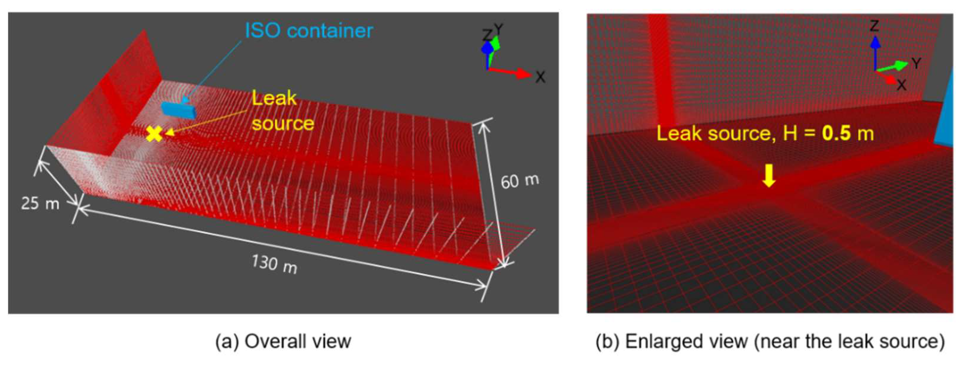
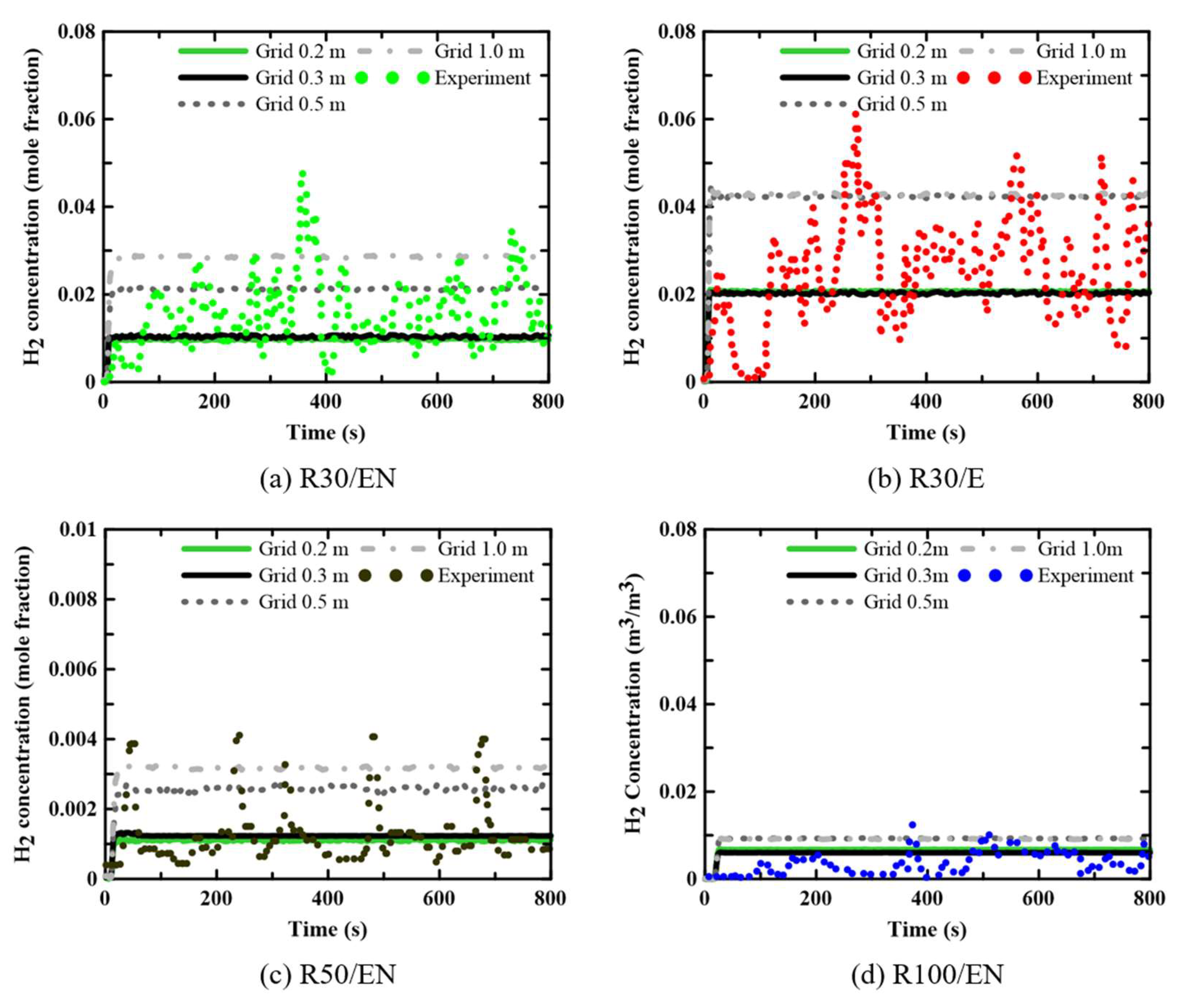
Prior to computation, we explored the grid sensitivity of the results. The minimum grid size was 2.25 cm in the 1 × 1 × 1-m
3 region (Region I) near the leakage source, considering the small pipe diameter. For the 20 × 20 × 20-m
3 space of the intermediate Region II (outside of Region I), around the leakage source, the grid size was gradually enlarged from 2.25 cm to 0.2, 0.3, 0.5, and 1.0 m. In the outermost Region III, the grid size gradually increased to a maximum of 10 m.
Table 3 lists the grid sizes and numbers for Region II, as well as the computation times necessary for each grid system. These times were 132 h for the smallest grid (0.2 m) and 48 h for the largest grid (1.0 m).
Figure 4 shows the computed and experimental variations in hydrogen concentration (the mole fractions) at radii of 30 and 50 m for a leaked mass flow rate (ṁ) of 0.73 kg/s. Although the experimental concentrations considerably changed over time, the computed concentrations were nearly constant except initially. The computational trend toward a constant hydrogen concentration over time reflects the RANS approach toward turbulent flow simulation. For grid sizes of 0.2 and 0.3 m for Region II, the computational results were similar, and the hydrogen concentrations were within the experimental ranges. Considering these data and the computation times shown in
Table 3, a grid of 0.3 m for Region II was appropriate; we used this grid in subsequent analyses. Although not shown here, it was confirmed that the computational results were not significantly affected by the grid size in the outermost Region III.
3.2. Prediction performance of three models for the liquid hydrogen release
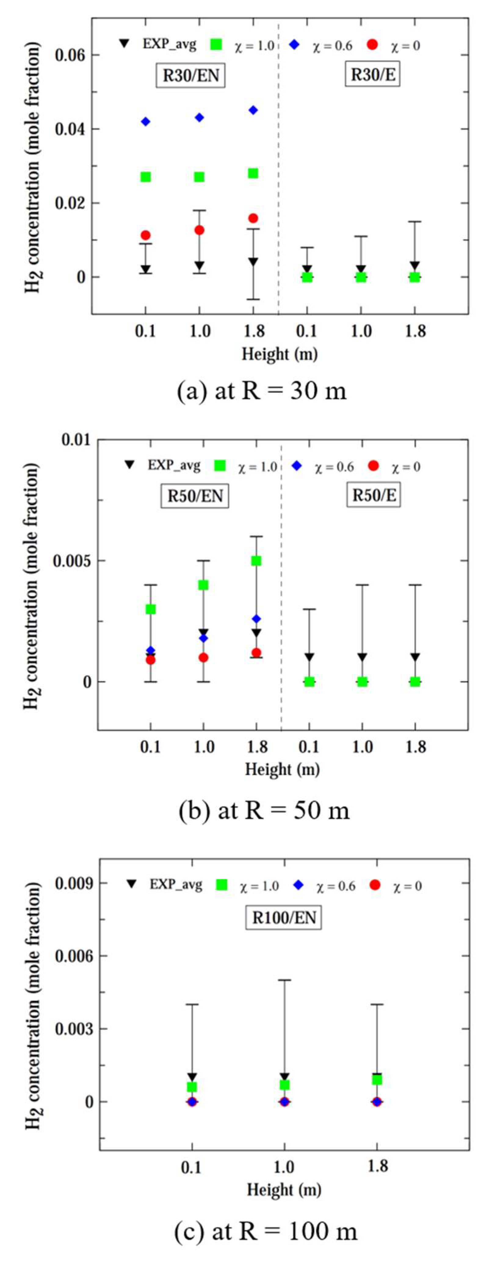
Figure 5 shows the computed and experimental hydrogen concentrations at radii of 30, 50, and 100 m, and heights of 0.1, 1.0, and 1.8 m, considering a smaller leaked mass flow rate (ṁ) of 0.225 kg/s. The black inverted triangular symbol represents the experimentally obtained time-averaged hydrogen concentration and the fluctuation bar indicates the maximum and minimum limits of concentration variation over time for the experimental concentration. The computed concentrations remained relatively constant, while the experimental concentrations exhibited significant fluctuations over time, as previously mentioned in
Figure 4.
For the locations of R30/E and R50/E, slightly offset from the wind direction, it can be observed that the computed values from all models were nearly identical and these computed values were close to the lower limits of experimental concentrations. For the R30/EN location, the pseudo-source model (χ = 1.0) and hybrid model (χ = 0.6) overestimated the experimental concentration, while the computed concentration by the liquid pool model (χ = 0.0) relatively well matched the experimental values. For the R50/EN location, the results from the three models were in the range of experimental fluctuations, but the pseudo-source model predicts the highest hydrogen concentration, while the liquid pool model predicts the lowest. For R = 100 m, the computed results were similar to each other, and fell within the fluctuation limits of experimental concentrations.
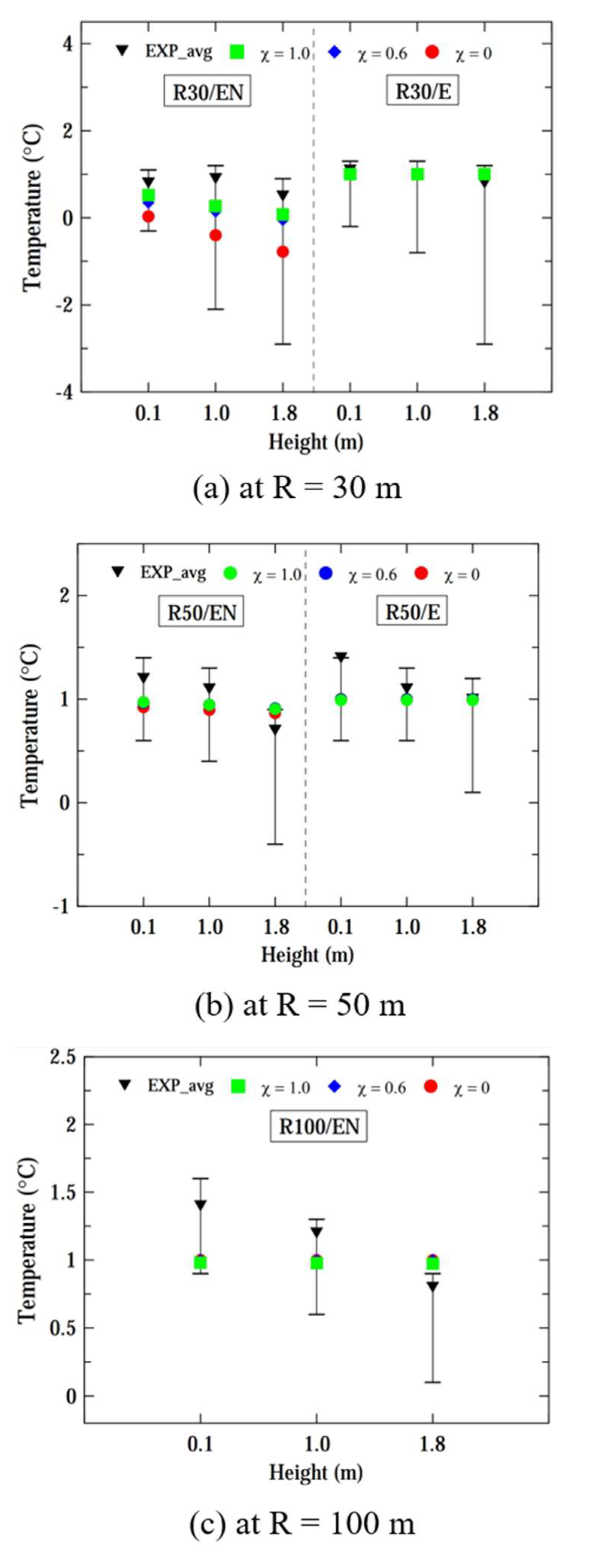
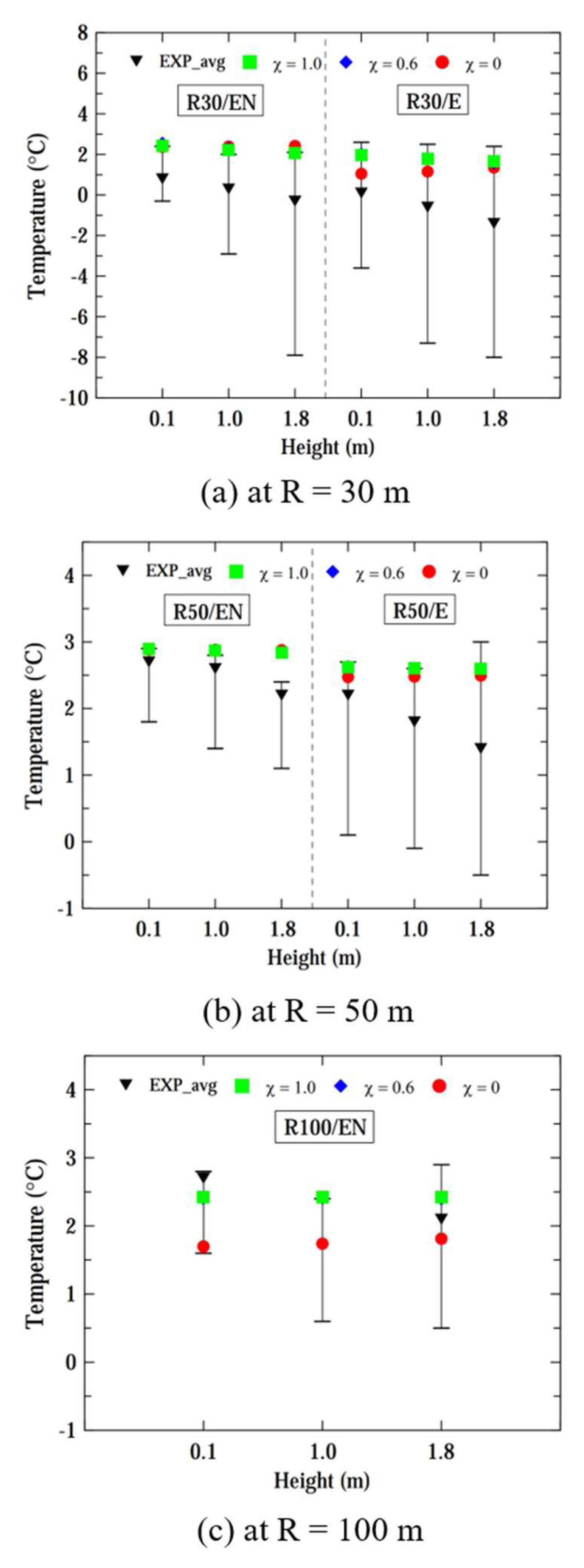
Figure 6 shows the computed and experimental temperatures of vapor clouds at radii of 30, 50 and 100 m for a case of ṁ = 0.225 kg/s. For all locations, the temperatures computed by three models fell within the fluctuation limits of experimental temperatures. The computed results from the three models were very similar for all locations, except that the temperature computed by the liquid pool model was slightly lower than those from the other two models for the R30/EN location. Considering the results of
Figure 5 and
Figure 6, it can be concluded that the liquid pool model performs better than the other two models for a smaller mass flow rate of ṁ = 0.225 kg/s.
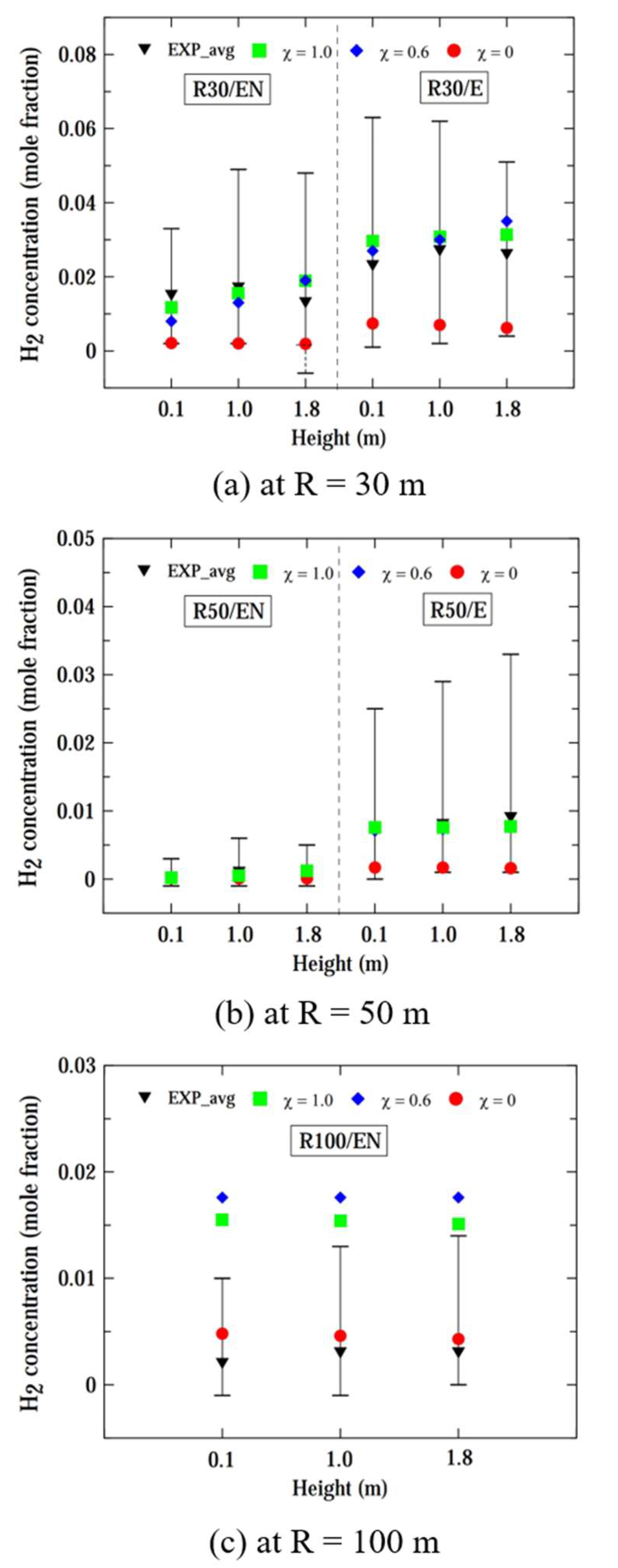
Figure 7 shows the computed and experimental hydrogen concentrations at radii of 30, 50, and 100 m, and heights of 0.1, 1.0, and 1.8 m, considering a leaked mass flow rate of 0.73 kg/s. For all radii and heights, the hydrogen concentrations were similar for χ = 1.0 and 0.6, whereas the concentration for χ = 0.0 was lower than the results predicted by the other two models. At radii of 30 and 50 m from the leak source, the simulation results of the pseudo-source model and hybrid model closely matched the experimental concentration near the time-average value. However, the computed concentrations for χ = 0.0 were closer to the minimum limits of experimental concentrations at distances of R ≤ 50 m. When considering locations at R ≤ 50 m with various directions, the results computed by all three models demonstrated reasonable prediction performance.
At location R50/EN aligned with the wind direction, the computed concentration more closely aligned with the experimental data compared to location R50/E. It is presumed that at a farther radial distance of R = 50 m, the location R50/EN is more directly influenced by the wind, resulting in a narrow range of fluctuations in hydrogen concentration compared to location R50/E.
At locations with R = 100 m, the concentrations for χ = 0.0 closely matched those of the experiment. Consequently, it was observed that the pseudo-source model and hybrid model provided better predictions for the experimental hydrogen concentration within a radial distance of 50 m. However, at a larger distance of R = 100 m, the prediction performance of both the pseudo-source model and hybrid model decreased compared to that at distances closer to the source of the leak.
Figure 8 shows the computed and experimental temperatures of vapor clouds at radii of 30, 50, and 100 m, considering a case of ṁ = 0.73 kg/s. Across all locations, the disparity in the prediction performance for temperatures computed by the three models was not significant within a distance of R ≤ 50 m. Overall, the computed temperatures fell within the range of experimental temperature fluctuations, but the computed results were closer to the upper limits of the fluctuation ranges. However, the computed temperatures computed by the liquid pool model were lower than those obtained by the other two models at R = 100 m.
Considering both the hydrogen concentration and ground temperature computed by the three models, the pseudo-source model and hybrid model appear to be more suitable for computing the dispersion for ṁ = 0.73 kg/s, except at R = 100 m, which is far from the source of the leak.
Hereinafter, considering the prediction performances for hydrogen concentration and vapor clouds temperature, we will describe the results using the pseudo-source model for a case of ṁ = 0.73 kg/s and the liquid pool model for a smaller mass flow rate case of ṁ = 0.225 kg/s.
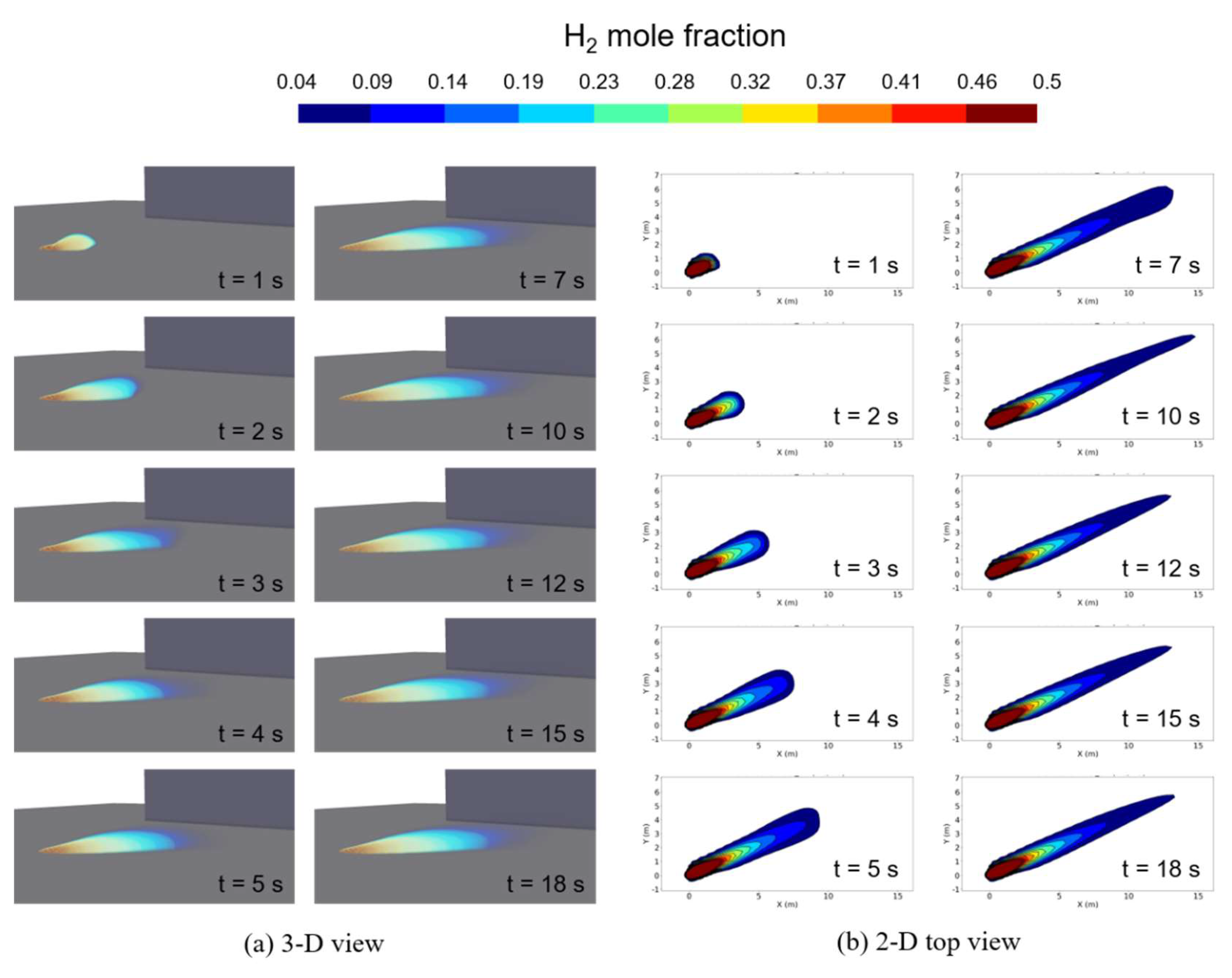
Figure 9 shows the 3-D and 2-D top views of the hydrogen concentration distribution on the ground obtained from the computation with the pseudo-source model for a case of ṁ = 0.225 kg/s. These visualizations effectively illustrate the process of hydrogen vapor dispersion as time progresses from the moment of leakage. From the initiation of the leak, hydrogen vapor dispersed mainly in the direction of the wind. However, comparing with the case of ṁ = 0.73 kg/s (shown in
Figure 10), the shape of hydrogen vapor clouds in the wind direction was narrower, and a V-shaped hydrogen vapor distribution was not observed from the 3-D and 2-D views.
From the 3-D distribution of hydrogen concentration, it became apparent that the approximate shape of hydrogen vapor clouds remained relatively unchanged after about 18 s from the start of the leak. This shape was also identifiable in the 2-D top view. Additionally, the distribution of hydrogen vapor plumes does not exhibit a shape with a noticeable end due to buoyancy effects. The wind speed for this condition was set to be 3.2 m/s. From the previous work, the hydrogen vapor cloud becomes buoyant at wind speed of 3.0 m/s or less [
11,
19]. While the wind speed meets the conditions for hydrogen vapor clouds to become buoyant, it is presumed that the reason hydrogen vapor clouds do not exhibit buoyancy characteristics is due to the very small amount of leaked liquid hydrogen.
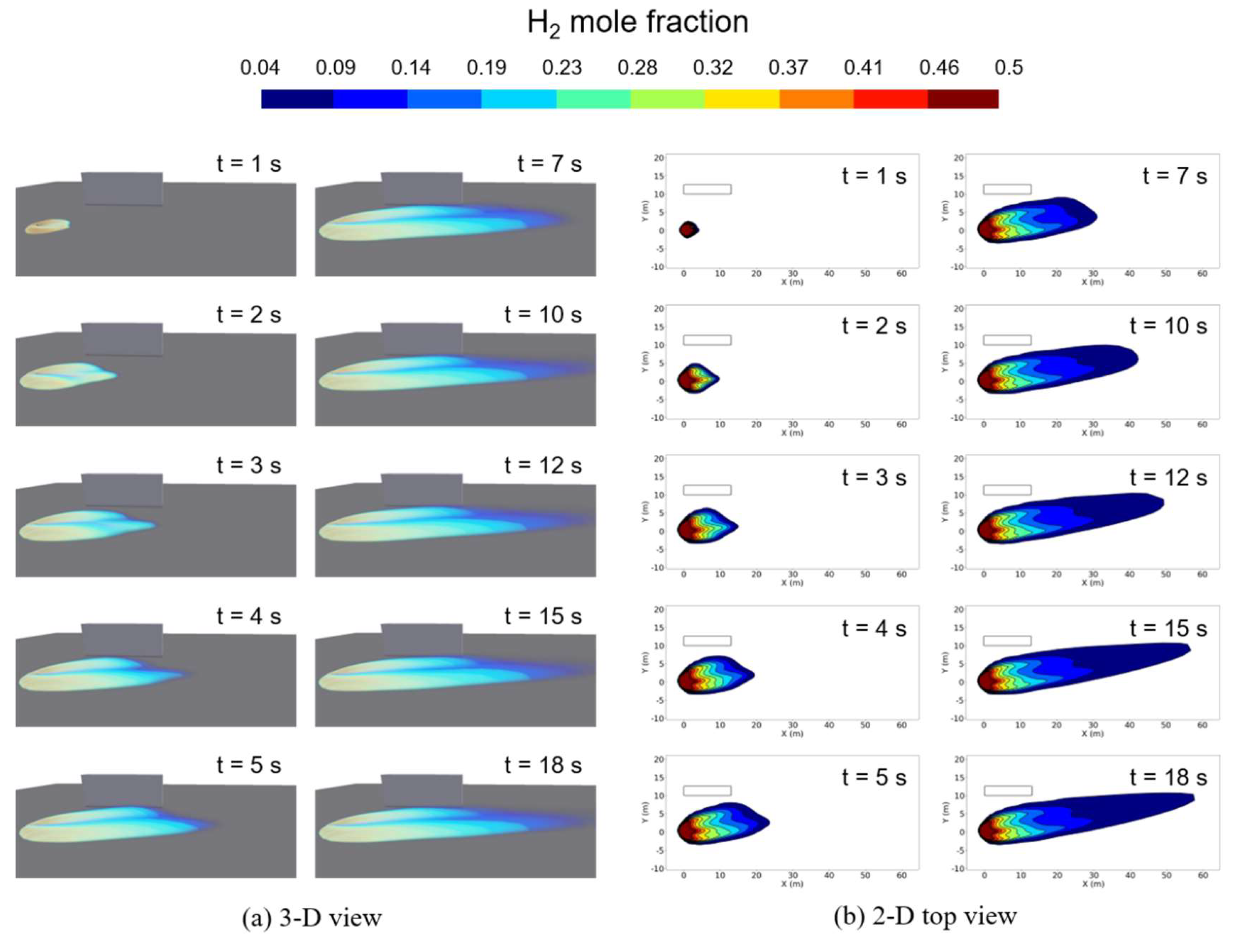
Figure 10 shows the 3-D and 2-D top view of the hydrogen concentration distribution on the ground obtained from the computation with the liquid pool model for a case of ṁ = 0.73 kg/s. The figures also effectively illustrate the process of hydrogen vapor dispersion for a larger leaked mass flow rate condition. From the initiation of the leak, hydrogen vapor dispersed mainly in the direction of the wind. In the 3-D view, it can be observed that hydrogen vapor clouds form a V-shaped distribution above the elliptical flat distribution along the wind direction. Furthermore, even as hydrogen dispersed after the leak, the vapor cloud's shape displayed minimal vertical dispersion due to buoyancy. The wind speed for this condition was set to be 5.2 m/s. This observation aligns well with previous findings [
11,
19], indicating that as wind speeds exceed 5.0 m/s, the vapor cloud dispersion tend to stay close to the ground.
3.3. Explosion of hydrogen vapor clouds
In this section, we investigated the explosion characteristics in cases where the vapor cloud, generated from the leaked liquid hydrogen, was ignited even though no ignition was introduced in the experiment. The ignition source was applied at a location where the equivalence ratio was approximately 0.8 to initiate the vapor cloud explosion since the hydrogen concentration was excessively high near the leak source of liquid hydrogen. For both hydrogen leakage flow conditions of ṁ = 0.225 and 0.73 kg/s, the ignition source was introduced 20 s after the liquid hydrogen began to leak.
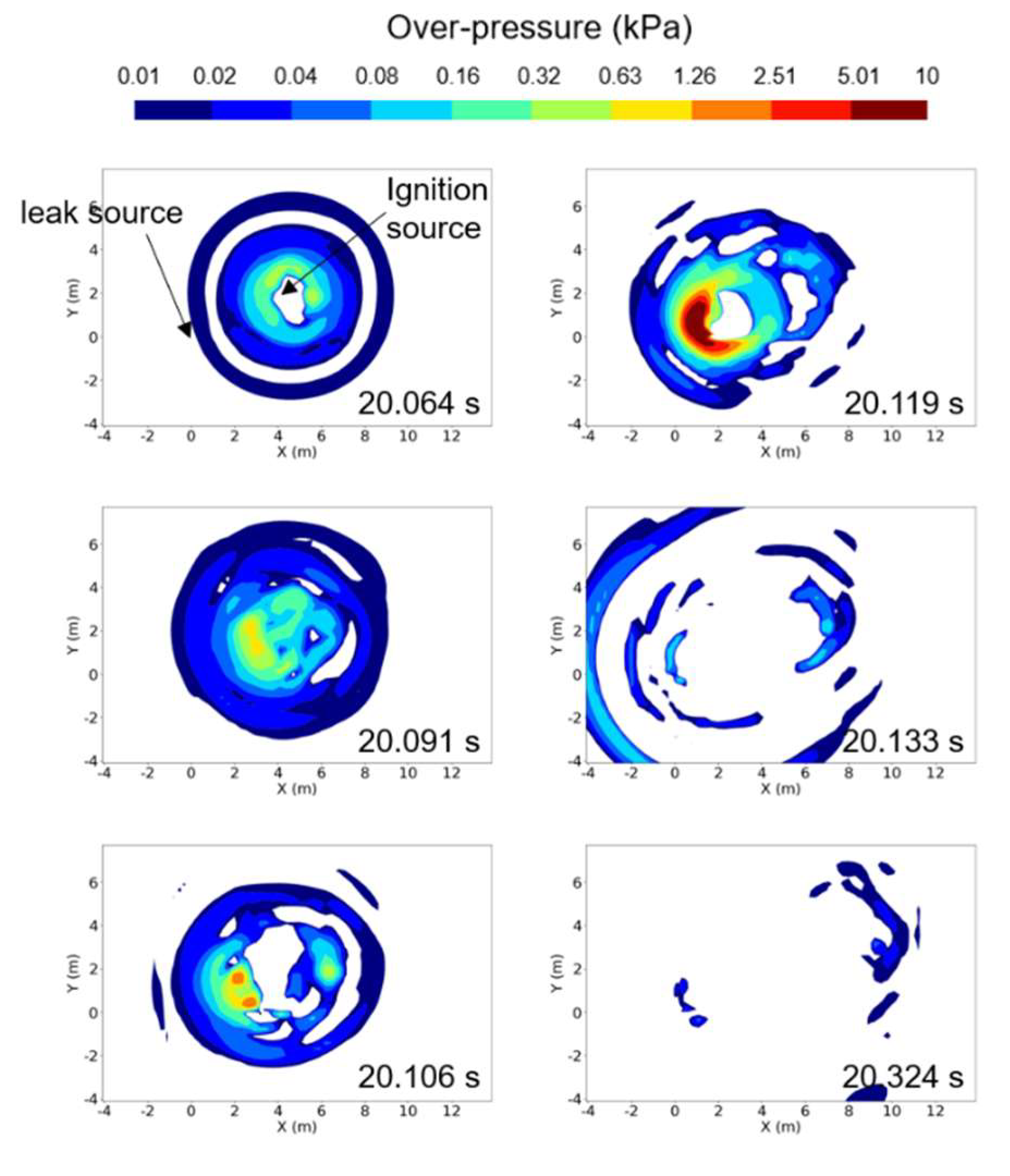
Figure 11 shows the overpressure distribution within a cross section of Z = 0.4 m during the explosion of a hydrogen vapor cloud, for a case of ṁ = 0.225 kg/s. In the figure, the coordinates (X, Y) with a position of (0 m, 0 m) represent the origin of the leak. For this condition, the ignition source was located at coordinates (4.0 m, 2.0 m) at the cross section of Z = 0.2 m. The highest overpressure was observed in the cross section of Z = 0.4 m, despite the ignition source being positioned at Z = 0.2 m. High overpressure began to generate near the ignition source and propagated in all directions, forming a maximum overpressure region near the leak source at approximately 20.119 s. At this time, the maximum overpressure recorded was 38.3 kPa, which was lower than that for a case of ṁ = 0.73 kg/s with a larger leakage mass flow rate. After the maximum overpressure was reached, it rapidly propagated in all directions and dissipated.
12 shows the overpressure distribution in a cross section of Z = 0.2 m. The highest overpressure was recorded in this section when the vapor cloud, resulting from a leak in liquid hydrogen, exploded for the case of ṁ = 0.73 kg/s. Similar to
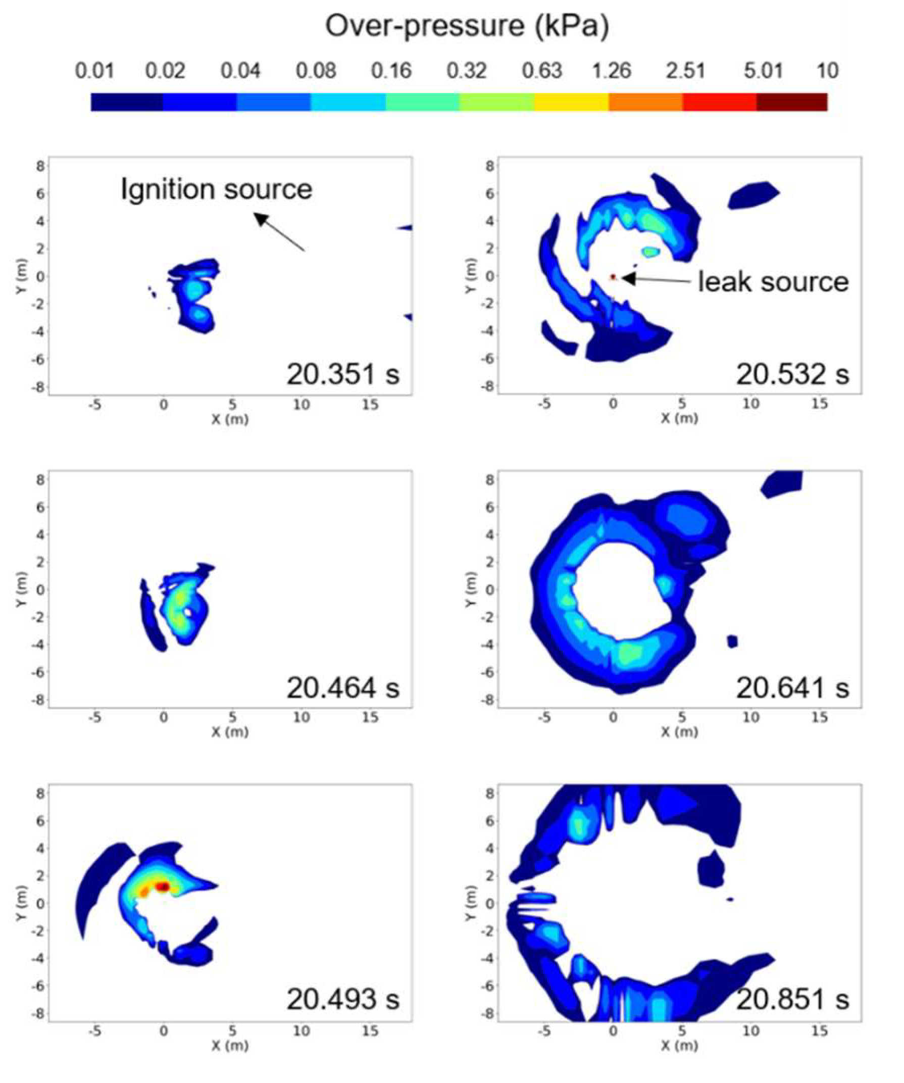
Figure 11, the coordinates (X, Y) with a position of (0 m, 0 m) represent the origin of the leak, while the coordinates (6.5 m, 4.2 m) denote the position of the ignition source. Following ignition, the explosion rapidly progressed, and at approximately 20.493 s after the onset of leakage, the maximum overpressure region was identified near the leak source, reaching a peak overpressure of 428 kPa. Subsequently, the overpressure rapidly propagated in all directions for a brief duration and gradually decreased.
Figure 12.
Computed overpressure distributions at the cross section of Z = 0.2 m, for a case of ṁ = 0.73 kg/s.
Figure 12.
Computed overpressure distributions at the cross section of Z = 0.2 m, for a case of ṁ = 0.73 kg/s.
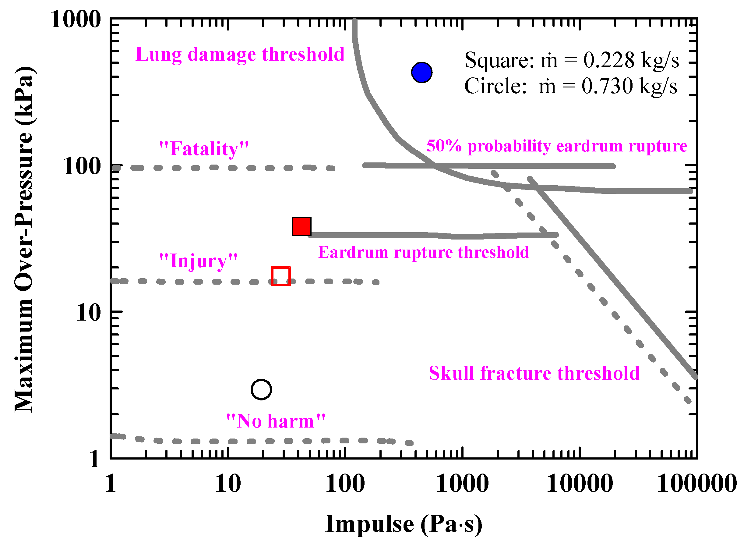
Figure 13 shows the overpressure-impulse diagram and damage thresholds for human by explosion [
28]. The overpressures and impulses were recorded at the locations of the maximum overpressure point and ignition point to assess the hazards to humans resulting from the explosions for the cases of ṁ = 0.225 and 0.73 kg/s. When an explosion occurs under the condition of a larger leaked mass flow rate, ṁ = 0.73 kg/s, the impact of the explosion is not severe enough to cause significant injuries near the ignition source. However, humans can still be strongly affected by the maximum overpressure and impulse, potentially resulting in fatal outcomes. Furthermore, in the case of a smaller leaked mass flow rate, ṁ = 0.225 kg/s, injuries can occur near the ignition source, and at the point of maximum overpressure, the damage can be severe enough to rupture the eardrum. As confirmed by the results, it is important to note that the damage caused by the explosion varies depending on the mass flow rate of the leaked liquid hydrogen. However, the magnitude and distribution of the explosion overpressure may vary depending on the location of the ignition source. In this study, the hydrogen vapor cloud was ignited 20 s after the liquid hydrogen began to leak, inducing the explosion. However, if the duration of the liquid hydrogen leakage is longer before ignition, resulting in a larger amount of leaked hydrogen, it is estimated that the overpressure caused by the explosion would increase further.
5. Conclusions
We utilized the FLACS code to computationally analyze the dispersion of a hydrogen vapor cloud resulting from liquid hydrogen leakage in an FFI experiments. The dispersion process was investigated using a pseudo-source model, a liquid pool model, and a hybrid model that combines both. We compared the computational results with experimental data regarding hydrogen vapor cloud concentration and temperatures to evaluate the prediction performance of each model. Additionally, we explored the potential impact of the explosion on humans when the leaked liquid hydrogen was ignited. Here are the key findings:
Hydrogen concentrations computed were relatively constant at all tested locations, except initially, while the experimental data showed significant variation over time. Predicted hydrogen concentrations were most accurate in the wind direction.
For a leaked mass flow rate of 0.73 kg/s, computational results closely matched experimental concentrations at a distance of 30 m from the leak source. Predictions were reasonable even at a distance of 50 m. The pseudo-source model and hybrid model performed similarly at distances of 30 and 50 m. However, at a distance of 100 m, these models slightly overpredicted, whereas the liquid pool model provided a more accurate prediction. The computed temperatures for each distance demonstrated good prediction, roughly within the range of experimental variations.
For a smaller leaked mass flow rate of 0.225 kg/s, the computations by pseudo-source model and hybrid model overestimated the experimental concentrations while the liquid pool model predicted the hydrogen concentration reasonably at a distance of 30 m from the leak source. Predictions by three models were generally reasonably for distances of 50 and 100 m. The computations also demonstrated reasonably prediction of the experimental temperatures for all locations.
In summary, for relatively large leaked mass flow rate conditions, the pseudo-source model or hybrid model appeared more appropriate for computation. Conversely, for small leaked mass flow rate conditions, the liquid pool model seemed more suitable.
Regarding explosion analyses, it is evident that larger mass flow rates (ṁ = 0.73 kg/s) can lead to maximum overpressure and impulse, potentially resulting in fatal outcomes. The impact of the explosion near the ignition source is less severe in this scenario. On the other hand, for lower mass flow rates (ṁ = 0.225 kg/s), injuries near the ignition source are possible, and severe eardrum damage can occur at the maximum overpressure point.
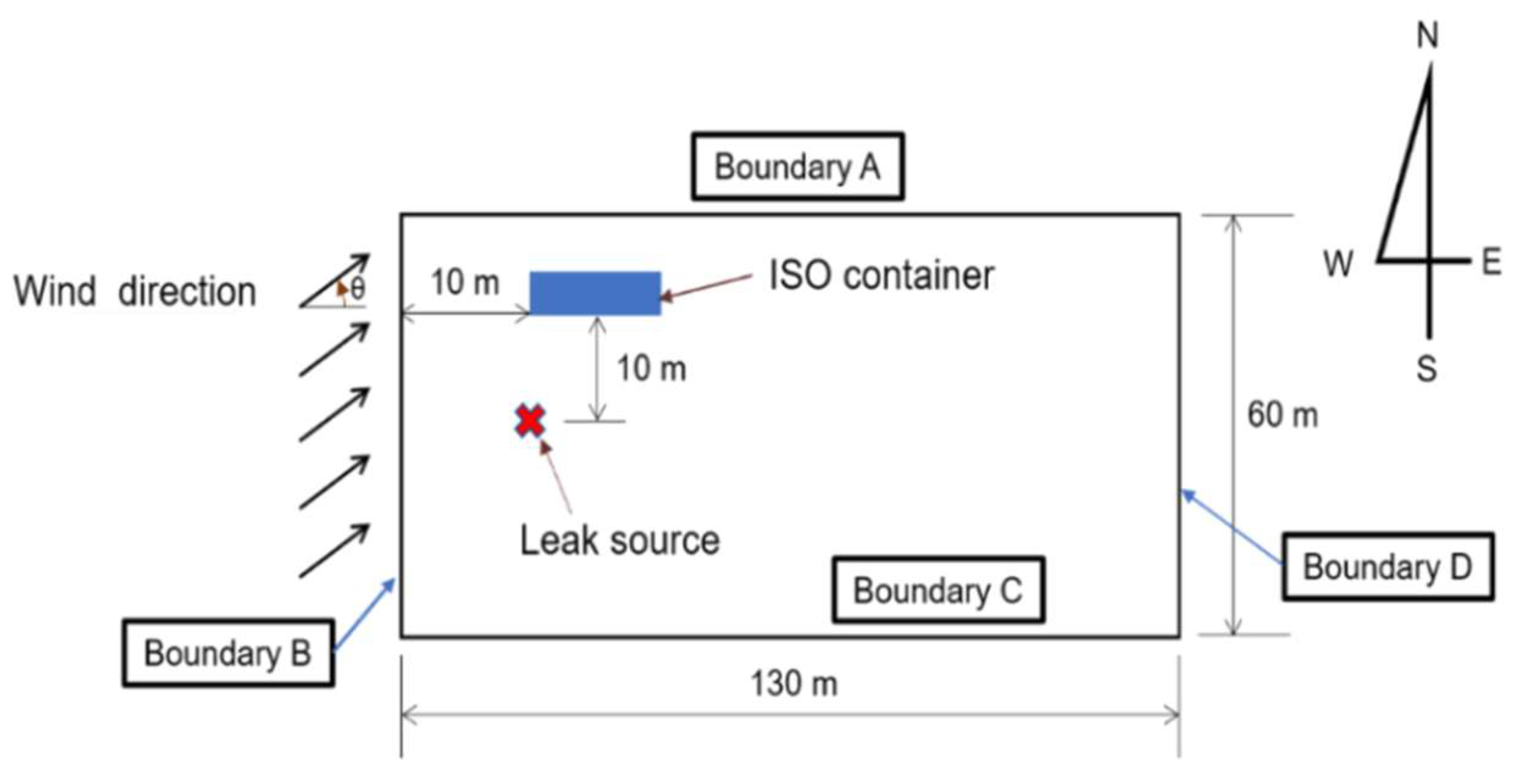
Figure 1.
Schematic of the computational domain showing the geometries of the leak source, obstacle and the surrounding environment.
Figure 1.
Schematic of the computational domain showing the geometries of the leak source, obstacle and the surrounding environment.
Figure 2.
The computational domain and the grid system.
Figure 2.
The computational domain and the grid system.
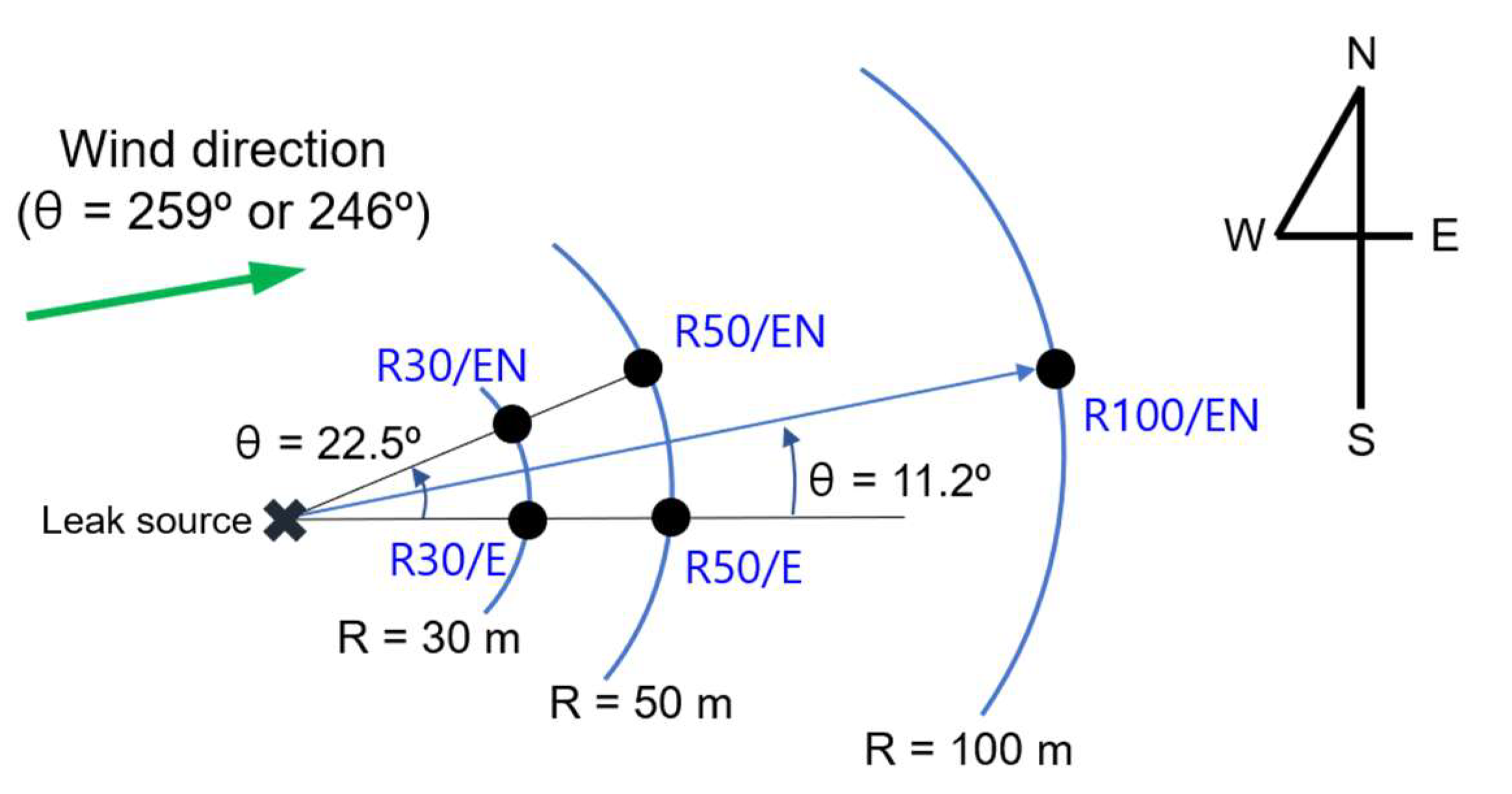
Figure 3.
Schematic of locations where hydrogen concentrations were measured.
Figure 3.
Schematic of locations where hydrogen concentrations were measured.
Figure 4.
Hydrogen mole fractions for different grid sizes at selected locations (grid sizes of 0.2, 0.3, 0.5, and 1.0 m for Region II, and at H = 1.0 m).
Figure 4.
Hydrogen mole fractions for different grid sizes at selected locations (grid sizes of 0.2, 0.3, 0.5, and 1.0 m for Region II, and at H = 1.0 m).
Figure 5.
Comparison of hydrogen concentrations computed by three models and those measured in the experiment at various locations for a case of ṁ = 0.225 kg/s.
Figure 5.
Comparison of hydrogen concentrations computed by three models and those measured in the experiment at various locations for a case of ṁ = 0.225 kg/s.
Figure 6.
Comparison of temperatrue computed by three models and those measured in the experiment at various locations for a case of ṁ = 0.225 kg/s.
Figure 6.
Comparison of temperatrue computed by three models and those measured in the experiment at various locations for a case of ṁ = 0.225 kg/s.
Figure 7.
Comparison of hydrogen concentrations computed by three models and those measured in the experiment at various locations for a case of ṁ = 0.73 kg/s.
Figure 7.
Comparison of hydrogen concentrations computed by three models and those measured in the experiment at various locations for a case of ṁ = 0.73 kg/s.
Figure 8.
Comparison of temperatrue computed by three models and those measured in the experiment at various locations for a case of ṁ = 0.73 kg/s.
Figure 8.
Comparison of temperatrue computed by three models and those measured in the experiment at various locations for a case of ṁ = 0.73 kg/s.
Figure 9.
Computed hydrogen concentration distributions for a case of ṁ = 0.225 kg/s.
Figure 9.
Computed hydrogen concentration distributions for a case of ṁ = 0.225 kg/s.
Figure 10.
Computed hydrogen concentration distributions for a case of ṁ = 0.73 kg/s.
Figure 10.
Computed hydrogen concentration distributions for a case of ṁ = 0.73 kg/s.
Figure 11.
Computed overpressure distributions at the cross section of Z = 0.4 m, for a case of ṁ = 0.225 kg/s.
Figure 11.
Computed overpressure distributions at the cross section of Z = 0.4 m, for a case of ṁ = 0.225 kg/s.
Figure 13.
Computed overpressures and impulses at selected locations for ṁ = 0.225and 0.73 kg/s (filled symbol: at the maximum overpressure point, vacant symbol: at the ignition point).
Figure 13.
Computed overpressures and impulses at selected locations for ṁ = 0.225and 0.73 kg/s (filled symbol: at the maximum overpressure point, vacant symbol: at the ignition point).
Table 1.
Conditions for liquid hydrogen release and weather [
17].
Table 1.
Conditions for liquid hydrogen release and weather [
17].
| case |
leaked outflow rate (kg/s) |
tank pressure (barg) |
wind speed (m/s) |
wind direction, θ (deg) |
ambient temperature (oC) |
weather conditions |
| 1 |
0.225 |
2 |
3.2 |
246 |
1.0 |
overcast, rain prior to test |
| 2 |
0.730 |
10 |
5.8 |
259 |
2.9 |
overcast, rain prior to test |
Table 2.
The Pasquill stability classes.
Table 2.
The Pasquill stability classes.
| Wind speed |
Day, strong sun |
Day, moderate sun |
Night, clouds (> 50%) |
Night, clouds (< 50%) |
|
2 m/s |
A |
B |
E |
F |
| 2–3 m/s |
A-B |
B-C |
E |
F |
| 3–5 m/s |
B |
B-C |
D |
E |
| 5–6 m/s |
C |
C-D |
D |
D |
|
6 m/s |
C |
D |
D |
D |
Table 3.
Grid sizes and computation times.
Table 3.
Grid sizes and computation times.
| Grid for Region II |
0.2 m |
0.3 m |
0.5 m |
1.0 m |
| Total number of grids |
1,576,440 |
713,934 |
328,328 |
150,144 |
| Computation time (wall clock time) |
132 h |
76 h |
52 h |
48 h |
