1. Introduction
Decarbonization of the transport sector is crucial to meet the Paris climate targets. This sector accounts for a significant
of global
emissions [
1]. The electrification of the powertrain is a highly promising measure for its decarbonizing. Numerous automobile manufacturers are pursuing this strategy and focusing their development plans on a complete shift to electric vehicles within the next decade. In addition, the European Parliament has decided that newly registered passenger cars and vans in the European Union will not be allowed to have an internal combustion engine from 2035 onwards [
2]. Already today, the sales of electric vehicles are increasing exponentially. In 2022, there were more than 26 million electric cars on the road, a fivefold increase compared to 2018 and a
increase compared to 2021 [
3]. However, battery electric vehicles (BEVs) currently cause almost twice as much greenhouse gas emissions in the manufacturing phase as comparable vehicles with combustion engines, mainly due to the resource-intensive production of the battery, in particular through the primary material preparation and the production of the battery cells [
4,
5].
Nevertheless, electric vehicle batteries (EVBs) have a significantly better environmental balance if renewable energies are used to charge EVBs during the use phase, and electrification takes place within a circular economy. In this context, the battery plays a crucial role. It is not only the most expensive component in BEVs, with a cost share of up to
, but it also contains valuable and strategic materials and components that need to be reused in order to (i) reduce greenhouse gas emissions from the mining, refining, and transportation of raw materials, (ii) reduce battery costs, and (iii) minimize supply dependency in the long term [
5].
Regardless of the circular economy strategies at the end of the life phase, EVBs must be disassembled [
6,
7]. The disassembly of EVBs is done manually nowadays, leading to bottlenecks for battery processing at the end-of-life stage. In addition, manual disassembly of such products poses safety risks, such as thermal runaway due to chemical chain reactions, fire hazards due to short circuits, and chemical leakage due to mechanical damage [
5,
8]. For these reasons, disassembly automation is a promising measure to promote the circularity of EVBs [
9].
Scientific publications in the field of disassembly mainly address three topics: (i) capacity planning, such as models for forecasting return quantities [
10,
11] (ii) disassembly line balancing, which is the process of allocating disassembly tasks to workstations [
12,
13], and (iii) disassembly strategy planning and optimization using one [
14] or several objectives [
15,
16]. According to Zhou et al. [
17], the disassembly sequence or strategy planning consists of three phases: (i) specifying the disassembly modes, (ii) model building, and (iii) disassembly strategy planning and optimization. The disassembly modes have been described in detail in our publication Al Assadi et al. [
7].
Only a few publications have dealt with the planning and optimization of disassembly scenarios for electric vehicle batteries. Choux et al. [
18] proposed a task planner for the robotic disassembly of electric vehicle packs. The authors focused only on identifying and localizing components to create a feasible disassembly plan. Wegener et al. [
19] presented an approach for disassembly sequence planning using the battery of the Audi Q5 Hybrid as an example. Alfaro-Algabra et al. [
20] proposed a multi-objective function to optimize disassembly strategies while maximizing economic profit and minimizing the environmental impacts. The authors demonstrated the methodology using an Audi A3 Sportback e-tron hybrid battery pack. Ke et al. [
21] provided a methodology to determine the shortest disassembly path of EVBs based on frame-subgroup structure and a genetic algorithm. Xiao et al. [
22] presented a disassembly sequence optimization method based on the dynamic Bayesian network that can handle the uncertainty of battery categories and quality. In our previous publication Baazouzi et al. [
23], we developed an optimization method for obtaining optimal disassembly strategies for EVBs as a combination of three decisions: (i) the optimal disassembly sequence, (ii) the optimal disassembly depth, and (ii) the optimal circular economy strategy at the component level.
All the mentioned papers focused on the three theoretical disassembly planning steps: (i) product representation, (ii) sequence research and (iii) solution optimization [
24]. To the best of our knowledge, no simulation models have been published that simultaneously takes into account the battery design and the configuration of the disassembly station to investigate disassembly scenarios.
This paper proposes a self-configuring simulation model for investigating disassembly strategies. Our approach combines discrete-event and agent-based modeling to automatically create and initialize a multi-method model that considers the battery design and the layout and sybsystems of the disassembly station.
The rest of the paper is organized as follows.
Section 2 describes the methodology, which consists of (i) preprocessing to collect the necessary data and define the disassembly scenarios and (ii) model building.
Section 3 presents the case study to demonstrate the functionalities of our simulation model. The results are presented in section 4 and discussed in section 5. In section 6, we briefly summarize the whole paper.
2. Methodology
2.1. Preprocessing
It is essential to systematically collect the fundamental information in a preprocessing phase to create a simulation model for planning and optimizing a disassembly strategy. This information is necessary for the investigation of disassembly scenarios and the analysis of the influence of the configuration of the disassembly station on the disassembly process, for example, regarding disassembly time and material flow.
The data collected during preprocessing must be stored in a structured way in a database to enable the automated creation of models that allow a detailed investigation of different disassembly scenarios. The preprocessing data can be divided into product-related, process-related, and product-process-related information. In the following subsections, these categories are explained. Thereby, exemplary data are mentioned, which serve as input data for the self-configuring multi-method model.
2.1.1. Product Preprocessing
In this phase, the components and their connections are recorded.
- (a)
Components
The components are recorded, whereby relevant data for disassembly planning and optimization, such as position, geometry, and weight, are recorded. Of particular importance for disassembly planning are the precedence constraints. A precedence matrix P is used to derivate feasible disassembly sequences. This matrix describes the order of priority of the disassembly steps. It can be derived by performing manual disassembly tests or using CAD models of the product to disassemble.
Disadvantages of manual preprocessing are the resource intensity and the error proneness, especially for complex products. CAD models also have disadvantages because they can rarely describe products reliably at the end of their life cycle, for example, due to corrosion or changes made to the product during the use phase.
During the disassembly tests, a disassembly precedence graph is generated. This graph is used to create the precedence matrix by directly comparing all components. If a component i represents a predecessor of another component j is filled with 1; otherwise, it is filled with 0.
- (b)
Connections
The connections are listed, categorized, and assigned to the corresponding components. Furthermore, the accessibility of the connections is an essential factor in defining the disassembly scenarios. This paper introduces two disassembly scenarios: Scenario 1 - Component-oriented disassembly and Scenario 2 - Accessibility-oriented disassembly.
In the first scenario, only the connections of the component i to be disassembled are disconnected. Only after this component has been removed the connections of the following components can be removed. In the second scenario, the connections of component i are detached, whereby accessible connections of subsequent components that require the same disassembly tool may be disconnected. Accessibility-oriented disassembly aims to minimize the number of tool changes, thus reducing the total disassembly time.
In the following, both scenarios are demonstrated in more detail through a hypothetical product in
Figure 3.1. The product comprises three components (
,
and
).
is attached to
using two type A connections.
is attached to
by two type A connections and an additional type B connection. Type A connections are loosened using tool 1, while type B connections require tool 2. The same gripper can remove all components. In this case, five tool changes are required for component-oriented disassembly. In contrast, the accessibility-oriented disassembly requires only four tool changes.
To model the accessibility of the connections, a dynamic accessibility matrix Z is defined, which is updated after each disassembly step. The initial accessibility matrix is filled in during the product preprocessing phase: If a component i hides a connection j, is filled with 1; otherwise, with 0.
Figure 1.
Demonstration of the disassembly scenarios Component-oriented and Accessibility-oriented on a hypothetical product: (C) Component, (T) Tool, (G) Gripper, 1, 2, 3, 4, und 5: Connections.
Figure 1.
Demonstration of the disassembly scenarios Component-oriented and Accessibility-oriented on a hypothetical product: (C) Component, (T) Tool, (G) Gripper, 1, 2, 3, 4, und 5: Connections.
2.1.2. Process Preprocessing
In this phase, information concerning the subsystems of the disassembly station is recorded.
- (a)
Robot
The robot arm moves the tools and grippers during the disassembly process. When planning and optimizing this process, dynamics-related data are of primary importance. However, during the process preprocessing phase, it is only possible to estimate these data due to the interlinked kinematics. In addition, the dynamics vary depending on the load because the weights of the tools, grippers, and components influence the final velocity, acceleration, and deceleration.
- (b)
Storage stations
The storage stations serve to collect the disassembled components. If no local pre-sorting is required at the disassembly station, placing all components at a single storage station is possible. They can be transported to the sorting station by forklifts or conveyor systems. However, using the disassembly robot for pre-sorting is also possible by providing several storage stations.
Different methods can be used for sorting, such as the type-based classification into different categories (mechanical components, electrical components, upper parts of the housing, lower parts of the housing, and remaining parts). The circular economy strategies, namely reuse, remanufacturing, repurposing, and recycling, can also be used for presorting the disassembled components. For this purpose, it is necessary to include these strategies in the planning and optimization of the disassembly strategy (see our previous publication [
23]).
- (c)
Processing table
The battery is placed on a processing table in order to be disassembled. The exact coordinates and dimensions of the processing table and positioning possibilities of the battery are essential information for planning the disassembly process.
- (d)
Disassembly tools and grippers
The individual components are removed successively according to a feasible sequence during the disassembly process. This process is performed in two main steps: (i) loosening the joining techniques using specialized disassembly tools and (ii) gripping and removing the separated component using appropriately adapted gripping mechanisms. For the planning of the disassembly strategy, precise information about the positions of the tools and grippers in the tool store of the disassembly station, as well as their respective application possibilities, are required.
2.1.3. Product-Process Preprocessing
In this phase, the disassembly strategy for detaching each connection is defined, including the assignment of the disassembly tools and grippers and a first estimation of the required process time. In addition, the storage position for each component is defined. Furthermore, the positioning of the battery on the processing table is determined. The placement of the battery influences the disassembly time because it significantly determines the length of the robot’s routes.
2.2. Model Building
A multi-method simulation approach is used to plan disassembly strategies and to investigate disassembly scenarios. This approach combines discrete-event and agent-based modeling. All elements from the preprocessing phase are described as agents in a generic way, allowing automatic model creation by generating the agents and assigning their properties based on the database captured in the preprocessing phase.
2.2.1. Model Setup
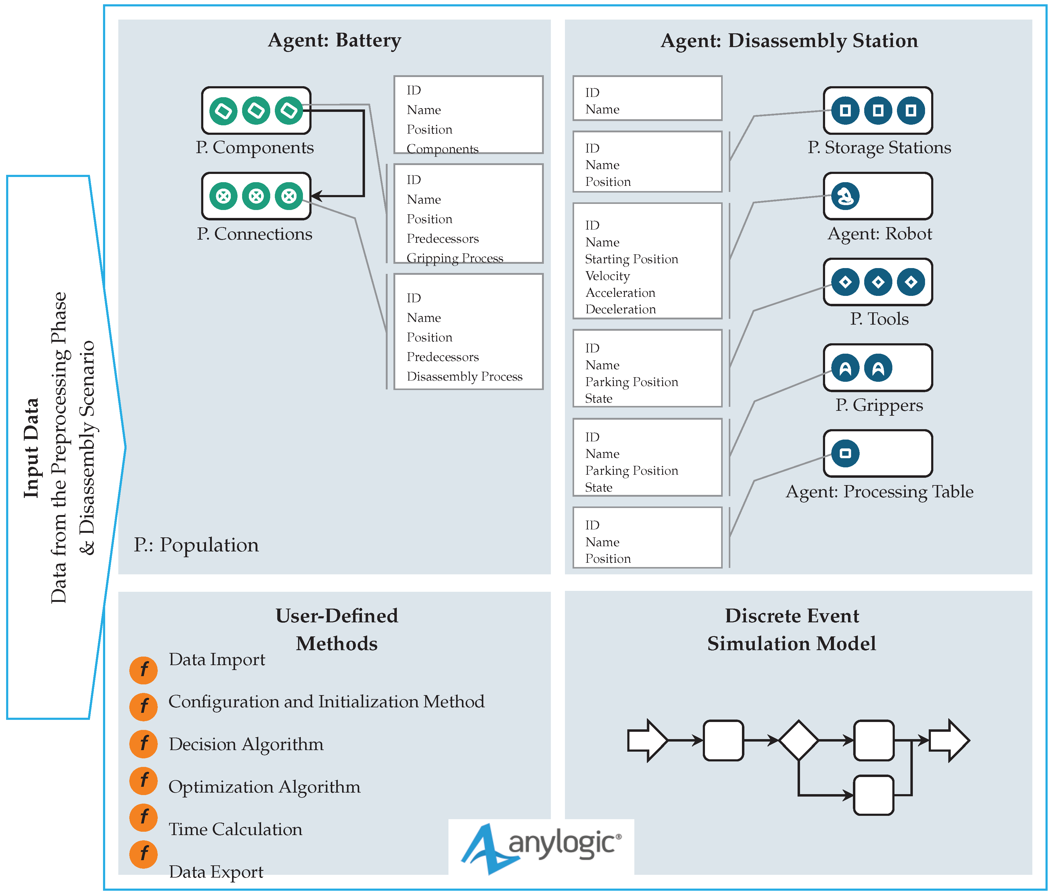
Figure 2 outlines the general model structure. At the beginning of the simulation, the data for the description of the battery to be disassembled and the disassembly station are imported using user-defined methods. This data comes from the preprocessing phase and is used to create, initialize, and assign the required agents to the appropriate populations. Additional user-defined methods are necessary to describe aspects of the model logic, such as defining decision rules.
2.2.2. Agents
The two main agents are the battery and the disassembly station. Within these agents, different populations exist, each representing the individual subsystems. The battery contains a population of components. Each component has a set of connections represented by a separate population within each component. The disassembly station comprises a robot, a processing table, storage stations, tools, and grippers. These components are also modeled using populations.
The behavior of agents can be defined by different methods that can be combined. Often, agents are characterized by their states and the actions and reactions of an agent depending on its current state. The agents’ behavior can also be defined by rules executed on certain events. User-defined methods or functions can define these rules. Additionally, the agent’s behavior can be defined by their internal dynamics, which stock and flow diagrams and process flow charts can describe. [
25]
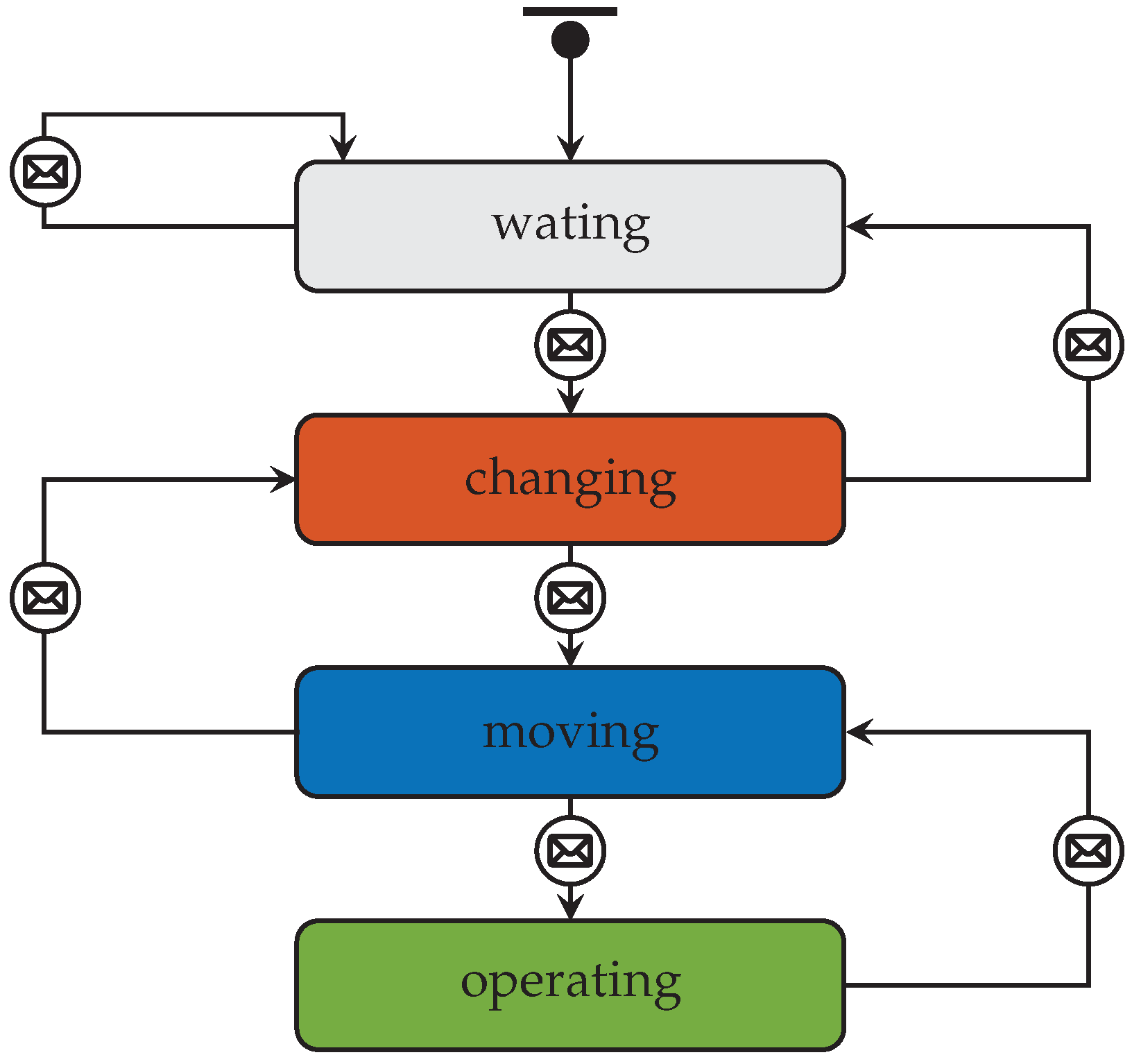
Figure 3 shows an example of the description of a tool in a state chart based on its states:
waiting: The tool is located at the tool station.
changing: The tool is taken for use or placed back after completing a process step.
moving: The tool is moved by the robot arm: (i) between the tool station and the processing table or the storage stations, (ii) between the processing table and the storage stations, or (iii) between two connections.
operating: The tool is in operation when it is used for a disassembly task or a gripping operation.
Figure 2.
Model structure: The model comprises the main agents, battery, and disassembly station, complemented by different subpopulations to model their components. The model logic is described in a discrete-event approach using a flowchart. User-defined methods are used in the import and export of data, the creation and initialization of the agents, and the description of the model logic.
Figure 3.
State chart of a disassembly tool. A state chart consists of states and transitions. Each transition has a trigger, such as a condition or a time limit. In this case, messages initiated by the discrete-event model, are used as triggers.
Figure 3.
State chart of a disassembly tool. A state chart consists of states and transitions. Each transition has a trigger, such as a condition or a time limit. In this case, messages initiated by the discrete-event model, are used as triggers.
2.2.3. Model Logic
AnyLogic’s process modeling library was used to implement the discrete-event model section for the generic description of the disassembly process. This library contains predefined elements that can represent processes as a sequence of operations in a flowchart [
26].
The logic of the implemented model is illustrated in
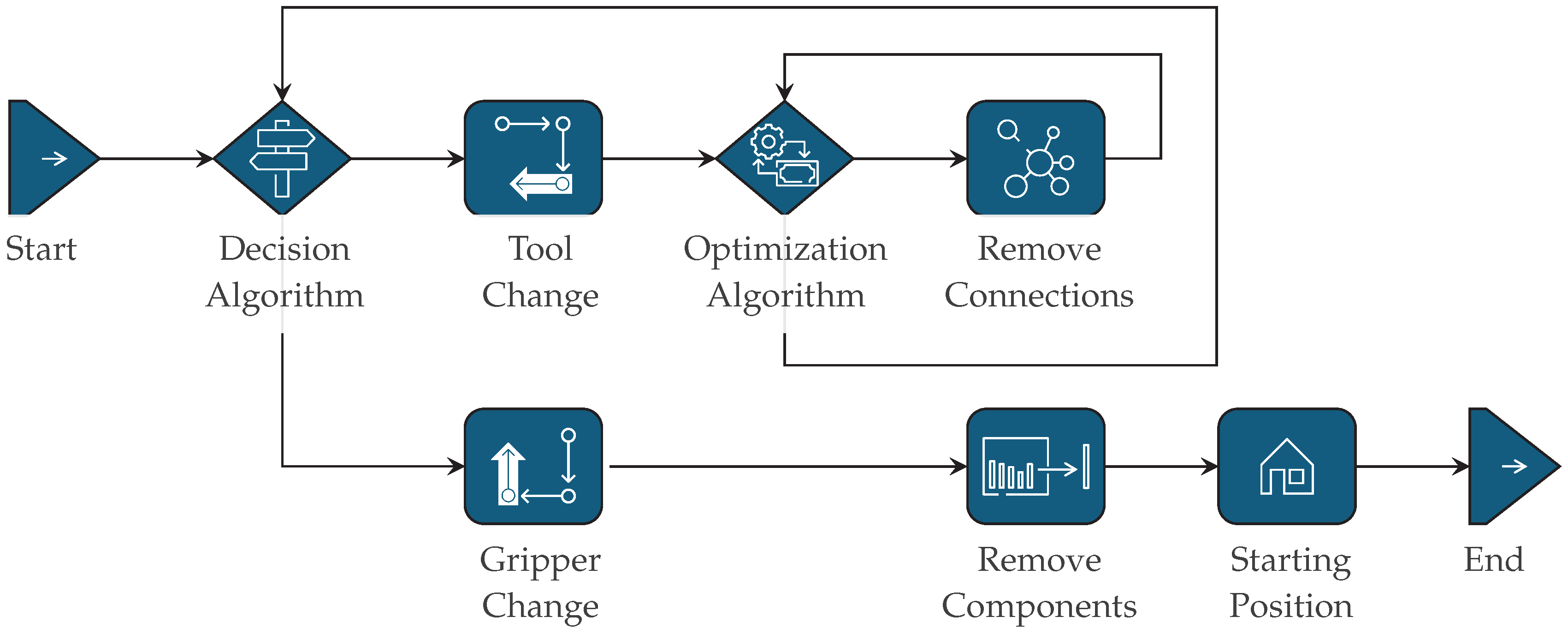
Figure 4. In the first step of the decision algorithm, it is checked whether components without connections exist and simultaneously fulfill the precedence relations. The priority in the disassembly process is to grip and remove these components. The order in which these components are removed is also specified. A component that satisfies the precedence relations is selected if no connection-free components are available. The connections of this component are removed step by step using the appropriate tools. Whether further connections may be removed in parallel depends on the selected disassembly scenario: Scenario 1 - Component-oriented disassembly and Scenario 2 - accessibility-oriented disassembly. Subsequently, the
Tool Changer agent ensures the required tool is available for the upcoming task.
Figure 4.
Model logic: For disassembling components, the corresponding connections are first detached using the appropriate tools. Then, the components can be removed with the appropriate gripper. Gripping operations to remove connection-free parts are prioritized during the disassembly process.
Figure 4.
Model logic: For disassembling components, the corresponding connections are first detached using the appropriate tools. Then, the components can be removed with the appropriate gripper. Gripping operations to remove connection-free parts are prioritized during the disassembly process.
The structure of the
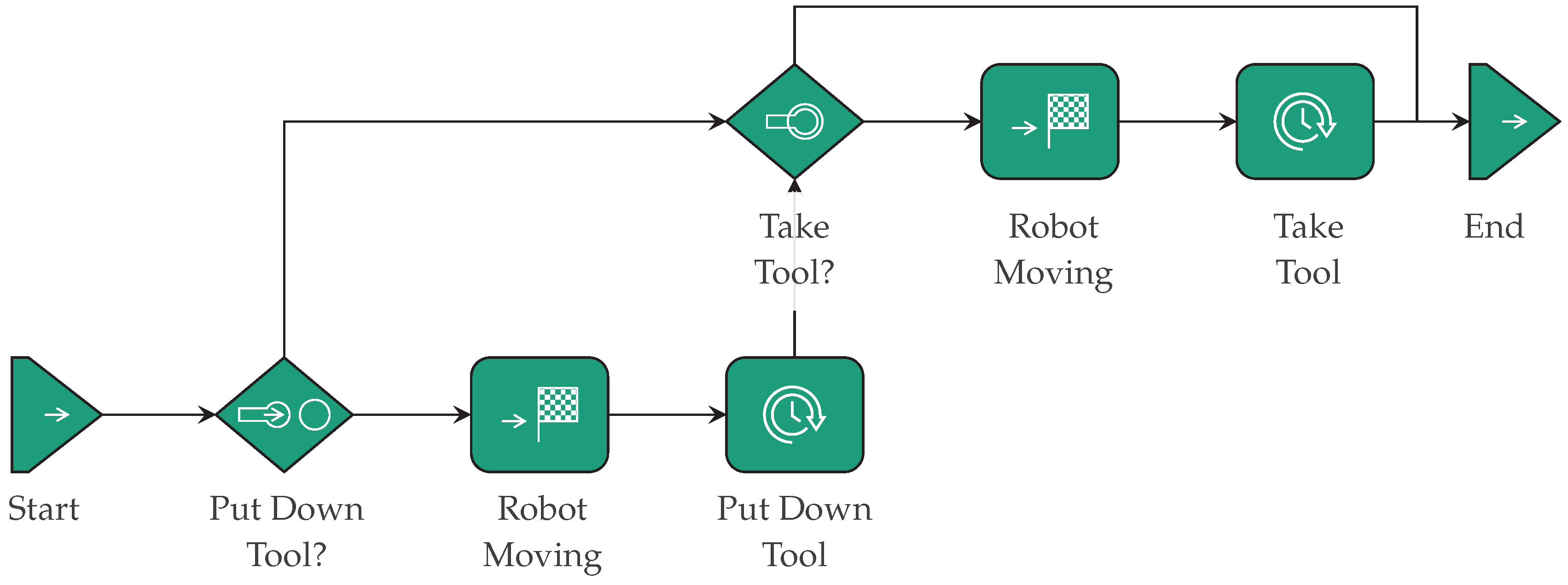
Tool Changer agent is shown in
Figure 5. First, it checks whether the tool currently on the robot matches the tool for the next disassembly operation. If this is the case, there is no need to travel to the tool station, eliminating the steps of placing and picking up the tool. At the beginning of the disassembly process, no tool deposit is required. In this situation, the robot moves to pick up the required tool. A regular tool change is performed by a robot movement to deposit a tool
i, followed by a movement to pick up another tool
j. Once the battery is completely disassembled, the last tool is deposited using the
Starting Position agent at the tool station.
Figure 5.
Structure of the agent Tool Changer. A tool change operation occurs when a tool i is put down and a tool j is taken up. No tool return is required at the beginning of the disassembly. The disassembly ends after the last gripper is placed in its parking position in the tool station.
Figure 5.
Structure of the agent Tool Changer. A tool change operation occurs when a tool i is put down and a tool j is taken up. No tool return is required at the beginning of the disassembly. The disassembly ends after the last gripper is placed in its parking position in the tool station.
2.2.4. Disassembly Path
The disassembly tour is calculated and optimized using the optimization algorithm to determine how the connections should be removed. In this context, we have a Traveling Salesman Problem. The optimization focuses on how a traveling salesman can visit a list of cities, visiting each city exactly once and returning to his starting city while covering the shortest possible distance [
27]. In the disassembly context, the connections represent the cities, and the position of the tool at the tool station represents the starting city. The Traveling Salesman Problem is a combinatorial optimization problem that can be solved using various heuristic methods. The solution space increases as the number of connections treated in a disassembly step with a specific tool grows. The number of possible disassembly sequences
of
connections of a component
k is calculated as follows:
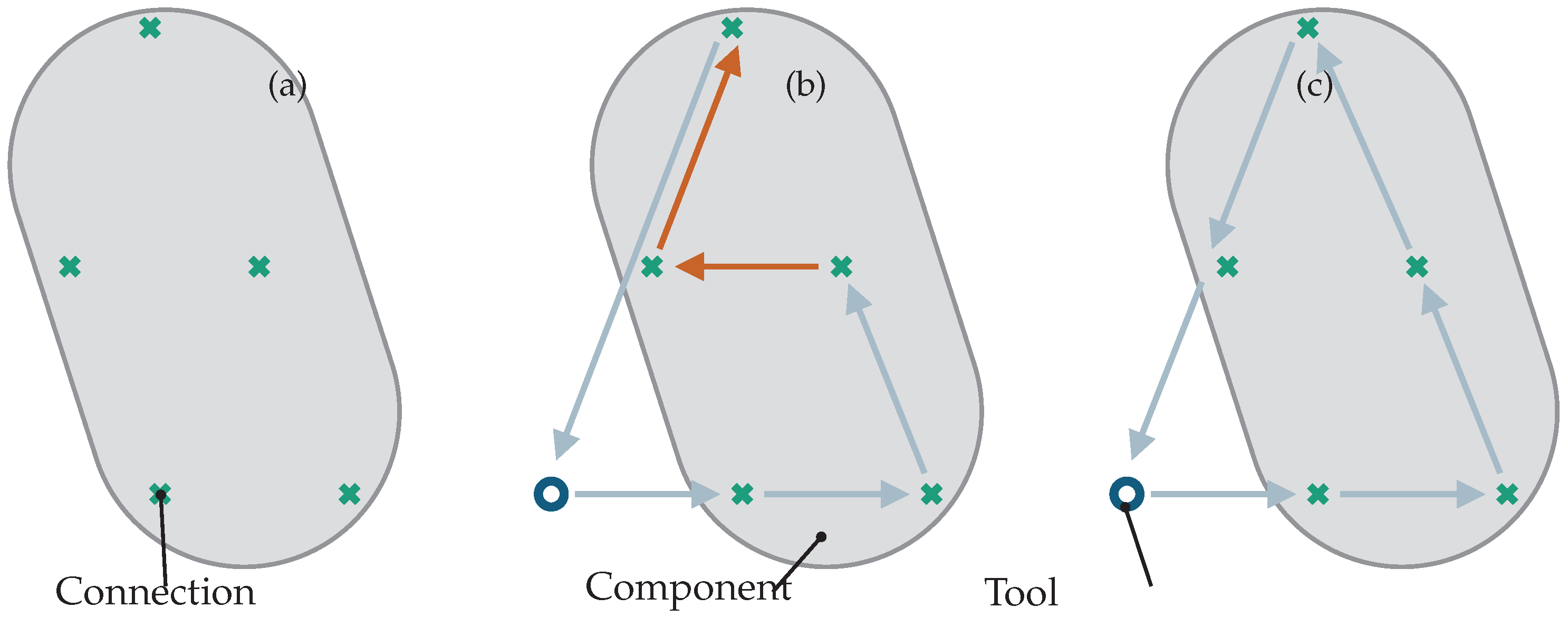
A two-step optimization was implemented in the developed model for studying disassembly scenarios. The robot route is approximated in the first step with the nearest neighbor method. The solution is then improved using the 2-opt method. The nearest-neighbor method approximates a tour by selecting the nearest point not yet visited in each step [
28]. While this method is simple, it is often not optimal and can lead to suboptimal solutions. The 2-opt algorithm optimizes the tour computed by the nearest-neighbor method stepwise by swapping edge pairs. Two edges in the tour are selected and swapped so that the total length of the tour is reduced. This process is repeated until no further improvements are possible [
29].
Figure 6 shows the disassembly route using the two-step optimization technique.
After calculating and optimizing the robot tour for removing a connection set, these are loosened. After that, the decision algorithm is used again to determine the next step: either a new connection set is specified and removed, or disconnected components are picked up by the corresponding gripper and transported to the appropriate deposit station. The logic of the gripper change follows the same logic as the tool change (see
Figure 5).
Figure 6.
Two-step method for optimizing the disassembly route from a connection set: (a) Component with five connections of the same type. (b) Disassembly route optimized using the nearest-neighbor method. (c) Disassembly route after using the 2-opt algorithm.
Figure 6.
Two-step method for optimizing the disassembly route from a connection set: (a) Component with five connections of the same type. (b) Disassembly route optimized using the nearest-neighbor method. (c) Disassembly route after using the 2-opt algorithm.
3. Case Study
The following case study will demonstrate the developed methodology for adaptive planning and optimization of disassembly strategies considering batteries and disassembly stations. A battery from a plug-in hybrid vehicle (PHEV) of Mercedes-Benz AG is used. It is a high-voltage battery weighing approximately 150 kg and has a total capacity of about 15.6 kWh [
30].
The test object in this work is voltage-free and has dummy battery cells to simplify the test setup. In this way, the safety risk during the disassembly tests is significantly reduced. Such batteries are used by OEMs (Original Equipment Manufacturers) to train production employees and commission production equipment. Further information about the battery can be found in our previous paper Rosenberg et al. [
31].
The disassembly station was developed within the research project
Industrial Disassembly of Battery Modules and Electric Motors (DeMoBat) at the Fraunhofer Institute for Manufacturing Engineering and Automation (IPA) [
32].
3.1. Battery
Figure 7 shows the structure of the battery. Only the components or subassemblies that must be removed to disassemble the module block are marked. The disassembly process begins with removing the clamping bars 1 to 4. A total of 40 screws are loosened and removed for this purpose. The clamping bars (1) to (4) are assembled with 13, 6, 15, and 6 screws, respectively. After this step, the upper part of the housing (5) can be disassembled and removed after the adhesive is cut. The disassembly aims to remove the module block (11), requiring loosening the connections of the module block, including eight base screws - four each on the left and right side - as well as four plug connections and two cable clamps. In addition, the module block is glued to the bottom part of the housing.
To make the connections of the module block accessible, two components on the right side and three on the left side have to be disassembled. These are the busbar with battery sensor (6), the support strut (7), the battery sensor (8), the busbar 2 (9) and the busbar 3 (10). By removing additional components, such as the air dryer and the battery management system, the accessibility of the module block connections can be further improved. However, it is not mandatory to disassemble these components.
To remove the busbar (6), two screws, one plug, and two cable clamps are loosened. The support strut is fixed with four screws. After loosening these screws, the component can be tilted and removed. When removing the battery sensor and the busbar 2 on the left side, one plug and two screw connections are loosened. The busbar 3 is fixed with four screws which have to be loosened. In addition, two plug connections and three cable clamps must be removed. There are a total of 80 connections that must be loosened in order to be able to remove the module block.
Figure 7.
Battery of Mercedes-Benz AG: (Left) Top view of the assembled battery: (Right) Top view of the opened battery after removal of the four clamping bars and the upper part of the housing. (1) clamping bar 1, (2) clamping bar 2, (3) clamping bar 3, (4) clamping bar 4, (5) upper part of the housing, (6) busbar with battery sensor, (7) support strut, (8) battery sensor, (9) busbar 2, (10) busbar 3, (11) module block, (12) remaining parts.
Figure 8 shows the precedence constraints of the battery represented by a disassembly precedence graph. From the graph, the precedence matrix
P is derived; see
Table 1. A zero-sum in column
i of the precedence matrix means that component
i satisfies the precedence conditions and can be disassembled. The
P matrix is dynamic during the numerical calculation of a feasible disassembly sequence by resetting all entries of row
i after removing component
i.
Figure 8.
Disassembly precedence graph of the investigated battery.
Figure 8.
Disassembly precedence graph of the investigated battery.
Table 1.
Precedence matrix of the battery. When a component i is a predecessor of another component j, is filled with 1, otherwise with 0.
Table 1.
Precedence matrix of the battery. When a component i is a predecessor of another component j, is filled with 1, otherwise with 0.
| |
1 |
2 |
3 |
4 |
5 |
6 |
7 |
8 |
9 |
10 |
11 |
12 |
| 1 |
0 |
0 |
0 |
0 |
1 |
0 |
0 |
0 |
0 |
0 |
0 |
0 |
| 2 |
0 |
0 |
0 |
0 |
1 |
0 |
0 |
0 |
0 |
0 |
0 |
0 |
| 3 |
0 |
0 |
0 |
0 |
1 |
0 |
0 |
0 |
0 |
0 |
0 |
0 |
| 4 |
0 |
0 |
0 |
0 |
1 |
0 |
0 |
0 |
0 |
0 |
0 |
0 |
| 5 |
0 |
0 |
0 |
0 |
0 |
1 |
0 |
1 |
0 |
0 |
0 |
0 |
| 6 |
0 |
0 |
0 |
0 |
0 |
0 |
1 |
0 |
0 |
0 |
0 |
0 |
| 7 |
0 |
0 |
0 |
0 |
0 |
0 |
0 |
0 |
0 |
0 |
1 |
0 |
| 8 |
0 |
0 |
0 |
0 |
0 |
0 |
0 |
0 |
1 |
0 |
0 |
0 |
| 9 |
0 |
0 |
0 |
0 |
0 |
0 |
0 |
0 |
0 |
1 |
0 |
0 |
| 10 |
0 |
0 |
0 |
0 |
0 |
0 |
0 |
0 |
0 |
0 |
1 |
0 |
| 11 |
0 |
0 |
0 |
0 |
0 |
0 |
0 |
0 |
0 |
0 |
0 |
1 |
| 12 |
0 |
0 |
0 |
0 |
0 |
0 |
0 |
0 |
0 |
0 |
0 |
0 |
3.2. Disassembly Station
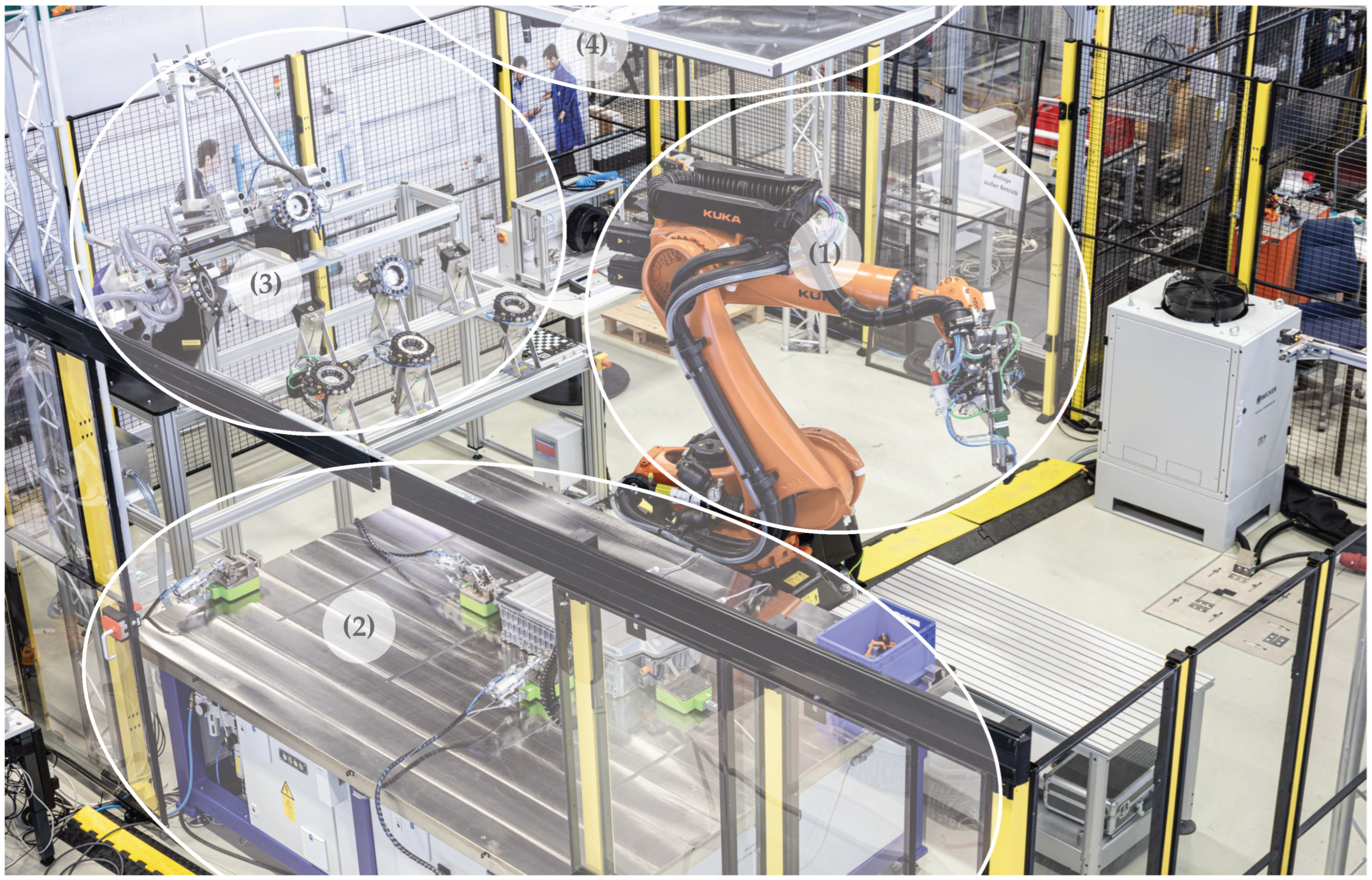
The disassembly station consists of four subsystems, see
Figure 9, which are a Kuka KR270 robot (1), a processing table (2), a tool station (3), and a vision system (4). On the processing table, there are fixture elements, which can be positioned anywhere and thus allow a flexible positioning of the battery [
33].
Figure 9.
DeMoBat disassembly station to extract modules from packs: (1) robot, (2) processing table, (3) tool station, (4) vision system. © Fraunhofer IPA/Photo: Rainer Bez. Own representation.
Figure 9.
DeMoBat disassembly station to extract modules from packs: (1) robot, (2) processing table, (3) tool station, (4) vision system. © Fraunhofer IPA/Photo: Rainer Bez. Own representation.
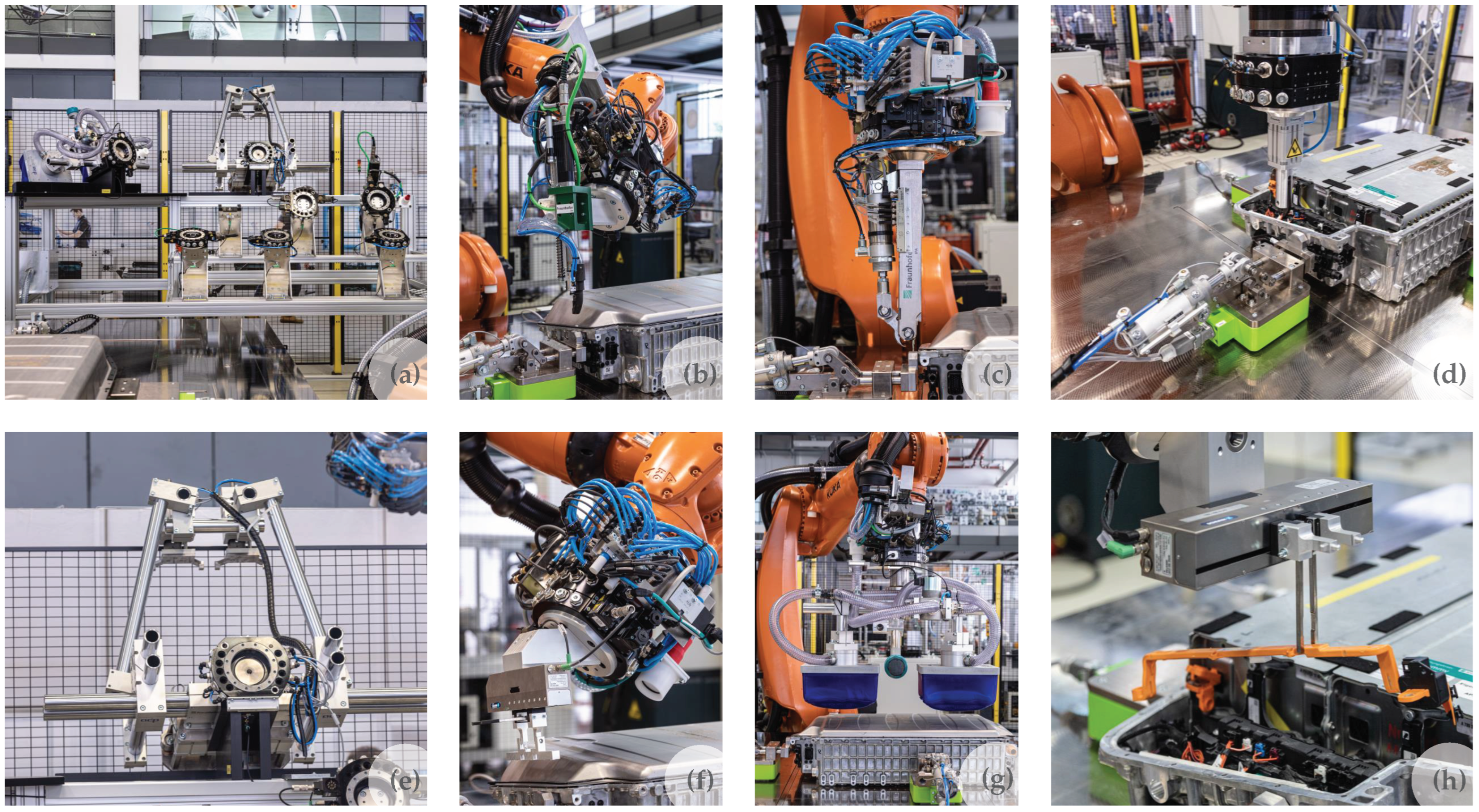
The tool station contains various universal tools; see
Figure 10. The
Unscrewer is used to loosen screws and remove them by suction. The
Opener is used to loosen the bonding of the upper parts of the housing. Two operation modes are possible: a discrete mode, where the bond is broken locally at defined cracking points, and a continuous mode, where the cracker cuts the bond along a joint. The
Cutter can be used to disconnect plugs and cable clamps. This is a partially destructive disassembly process as cables are cut. Non-destructive disassembly of plug connections is a complex engineering task due to design diversity and limited accessibility. The
Puller is used to loosen the modules’ bottom bonding and remove the modules from the housing. The Puller can be placed under the top plate of the battery modules. It presses pneumatically against the bottom part of the housing to allow the glued joint to be peeled off by applying force on one side. Small disassembled components can be removed with either the magnetic gripper (
Gripper 1) or the two-finger gripper (
Gripper 2). Housing shells and components with complex geometries can be gripped and removed with the
Formhand. This tool has flexible gripping pads filled with granules and thus conforms to the geometry and surface of the gripped object [
34].
Figure 10.
DeMoBat disassembly tools: (a) tool station, (b) Unscrewer, (c) Opener, (d) Cutter, (e) Puller, (f) magnetic gripper for small parts (Gripper 1), (g) Formhand, (h) two-finger gripper (Gripper 2). © Fraunhofer IPA/Photos: Rainer Bez. Own representation.
Figure 10.
DeMoBat disassembly tools: (a) tool station, (b) Unscrewer, (c) Opener, (d) Cutter, (e) Puller, (f) magnetic gripper for small parts (Gripper 1), (g) Formhand, (h) two-finger gripper (Gripper 2). © Fraunhofer IPA/Photos: Rainer Bez. Own representation.
3.3. Reference Scenario
The disassembly time in automated disassembly consists of three times. These are: (i) the tool change time
to pick up and put down tools, (ii) the traveling time
that the robot needs to perform the different routes, and (iii) the processing time
to carry out the disassembly activities, see equation
2. In the following, these three times are defined for a reference scenario.
3.3.1. Tool Change Time
The reference scenario assumes a tool change time of . This corresponds to the time in the DeMoBat station on a laboratory scale. A tool change usually consists of two phases: (i) tool deposit and (ii) tool pickup. For both phases, the time is required.
3.3.2. Traveling Time
The velocity
v, acceleration
, and deceleration
define the robot’s dynamics. During disassembly, short distances are often covered where the target velocity of the robot arm is not reached. This happens when several connections of the same type are loosened using the same tool. In such cases, the robot starts braking before the acceleration phase is completed. This effect is taken into account in the implemented dynamics model.
Table 2 shows the parameters used in the reference scenario.
Table 2.
Parameters for defining the robot dynamics.
Table 2.
Parameters for defining the robot dynamics.
| Parameter |
Name |
Value |
| v |
Velocity |
0.3 m/s |
|
Acceleration |
0.5
|
|
Deceleration |
0.5
|
3.3.3. Processing Time
The work situation in a disassembly plant was simulated on a laboratory scale in the disassembly experiments. Three disassembly experiments were carried out in which three employees disassembled the battery one after the other. The times were recorded. These were averaged to determine the process times for the reference scenario. This means that the automated process times are assumed to be the same as the manual times. The manual disassembly took an average of .
4. Results
4.1. Visualization of the Disassembly Steps
In the implemented simulation environment, the disassembly station and the battery to be disassembled are visualized, and the disassembly process is animated.
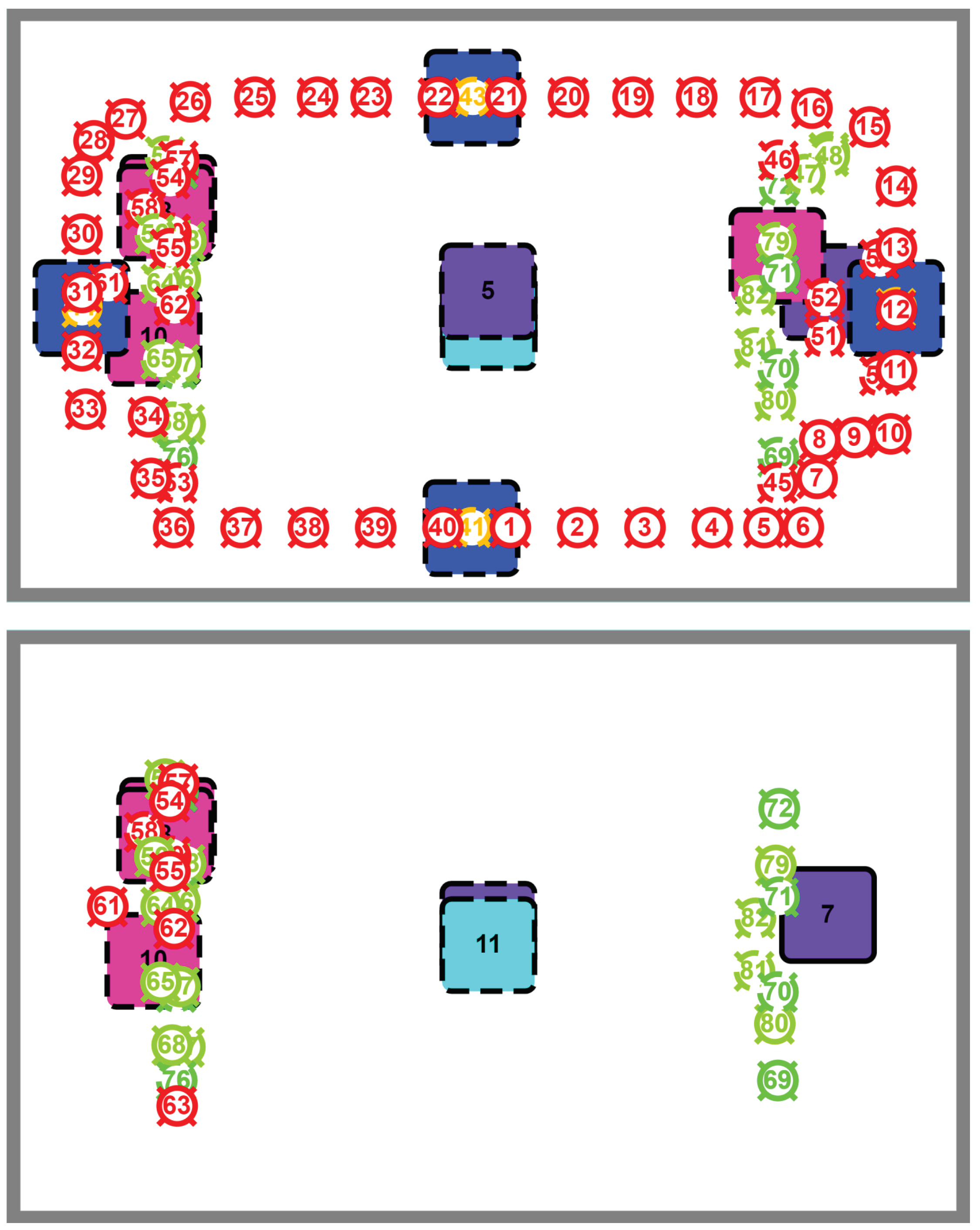
Figure 11 shows two screenshots of the battery during the simulation. The upper image shows the battery immediately before the disassembly process. The lower image shows a disassembly state after the removal of several components. The components are shown with rectangles, and the connections with circles. Accessible connection-free components and accessible connections for the disassembly tools are outlined with continuous lines. Components that have connections or do not fulfill the precedence conditions and inaccessible connections hidden by components are outlined with dashed lines.
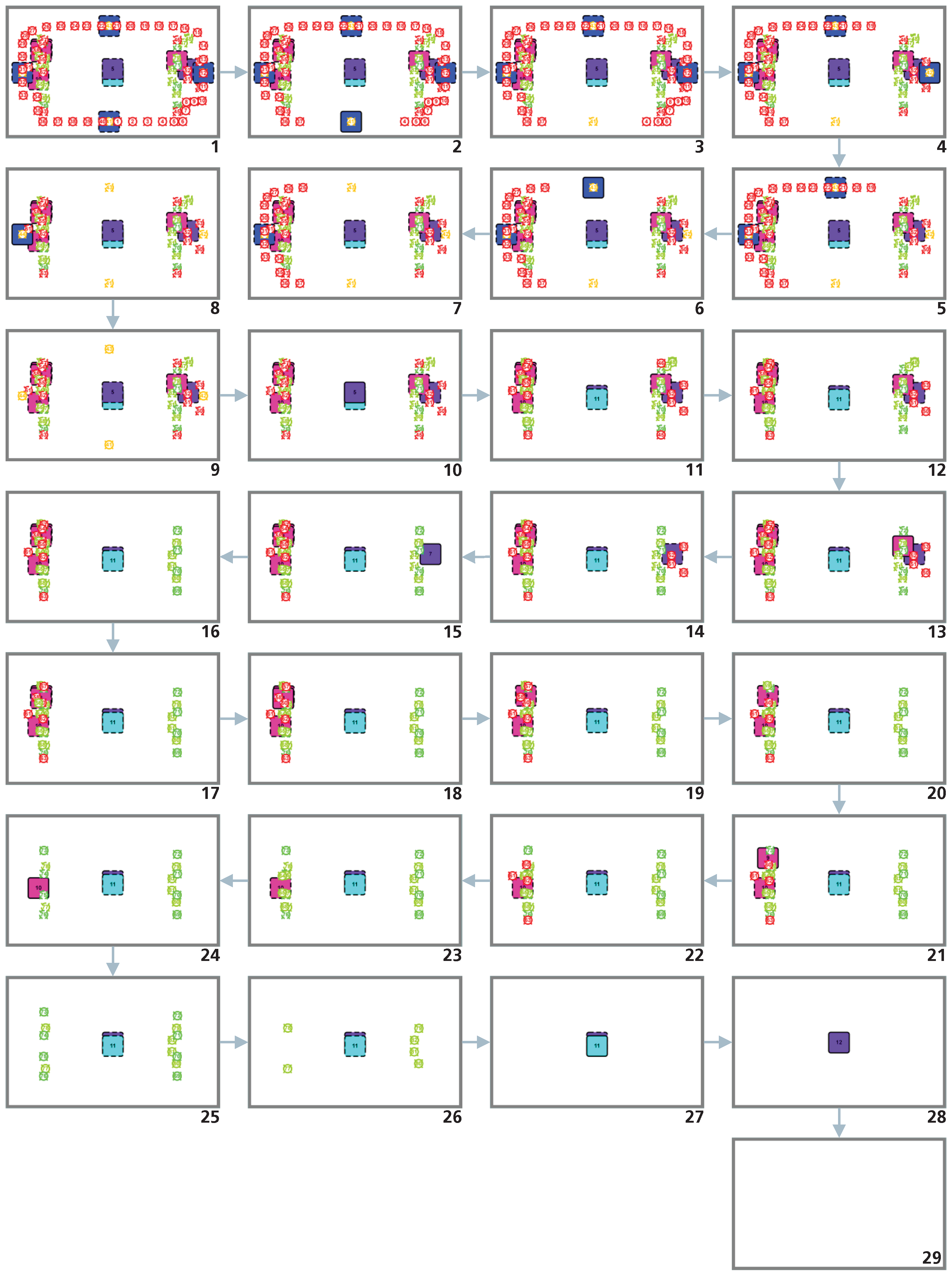
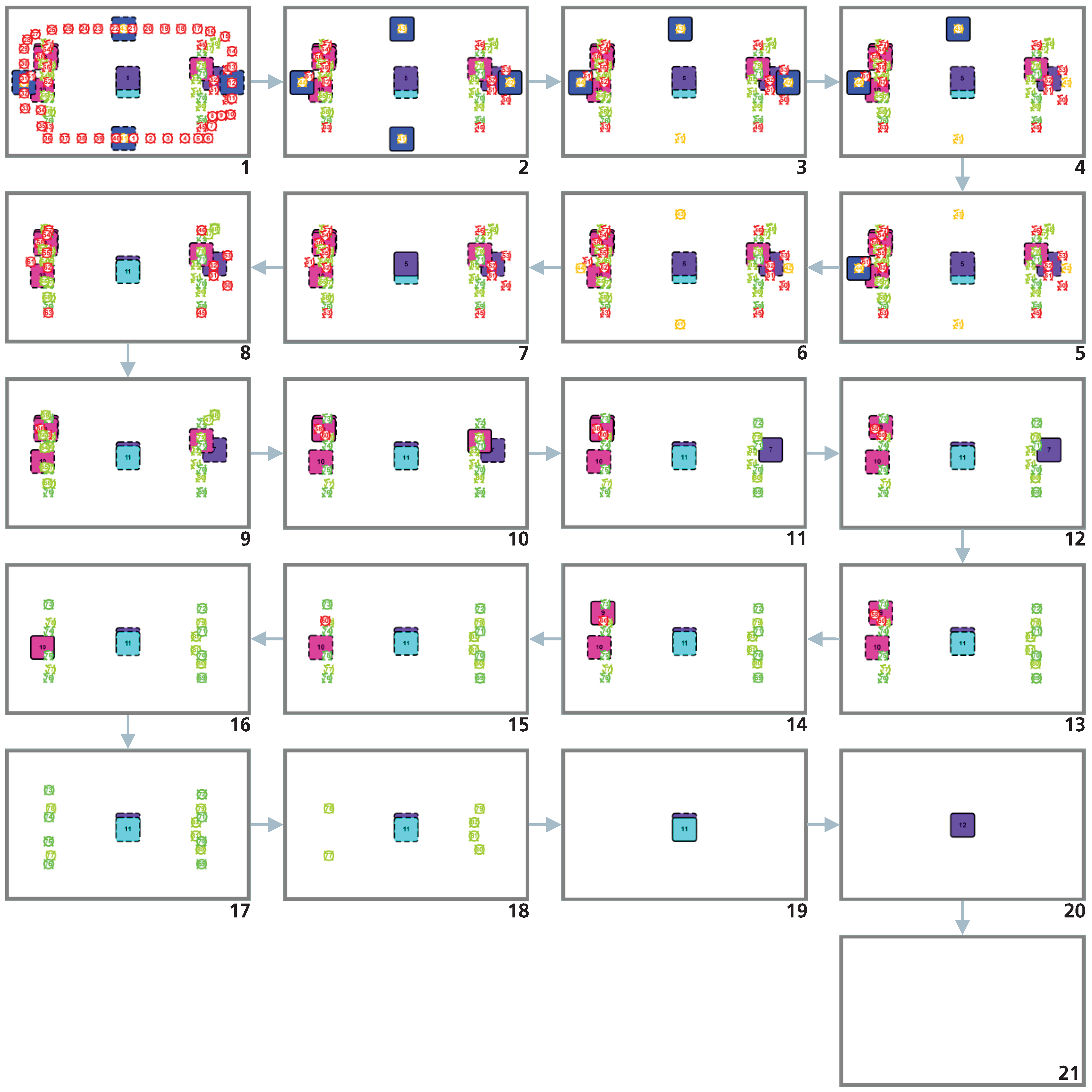
Figure A1 and
Figure A2 in the Appendix show the disassembly steps of the used Battery of the Mercedes-Benz AG for the component-oriented and accessibility-oriented disassembly scenarios.
Figure 11.
Visualization of the disassembly steps during the simulation: (top) non-disassembled battery. (bottom) a random disassembly stage. These are screenshots from the implemented simulation environment.
Figure 11.
Visualization of the disassembly steps during the simulation: (top) non-disassembled battery. (bottom) a random disassembly stage. These are screenshots from the implemented simulation environment.
4.2. Routes
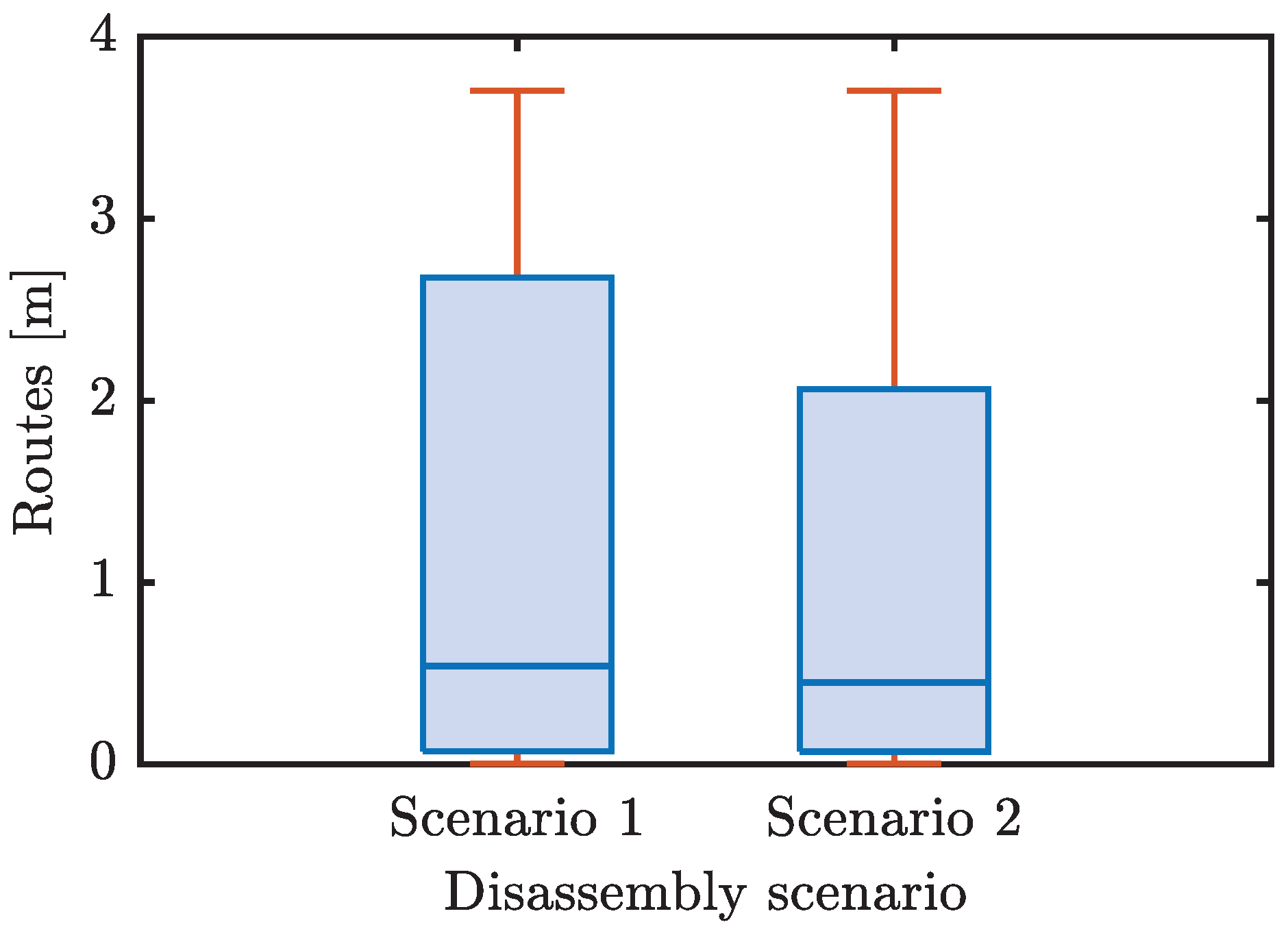
The box diagram in
Figure 12 illustrates the distribution of the covered distances in the two disassembly scenarios: Scenario 1 - Component-oriented disassembly and Scenario 2 - Accessibility-oriented disassembly.
In scenario 1, 162 routes are required to remove the module block. In comparison, only 138 routes are required in scenario 2, corresponding to a reduction of of the number of routes in scenario 2 compared to scenario 1.
The third quartile of route lengths, represented by the box’s upper boundary in the box diagram, decreases from in scenario 1 to in scenario 2. This significant decrease in the upper quartile indicates that the number of long distances in the second scenario is reduced. At the same time, the median of the distances decreases from in scenario 1 to in scenario 2. This shift of the median value indicates that the mean distance length is reduced in scenario 2.
Figure 12.
Box diagram showing the routes traveled by the robot arm for component-oriented (Scenario 1) and accessibility-oriented (Scenario 2) disassembly.
Figure 12.
Box diagram showing the routes traveled by the robot arm for component-oriented (Scenario 1) and accessibility-oriented (Scenario 2) disassembly.
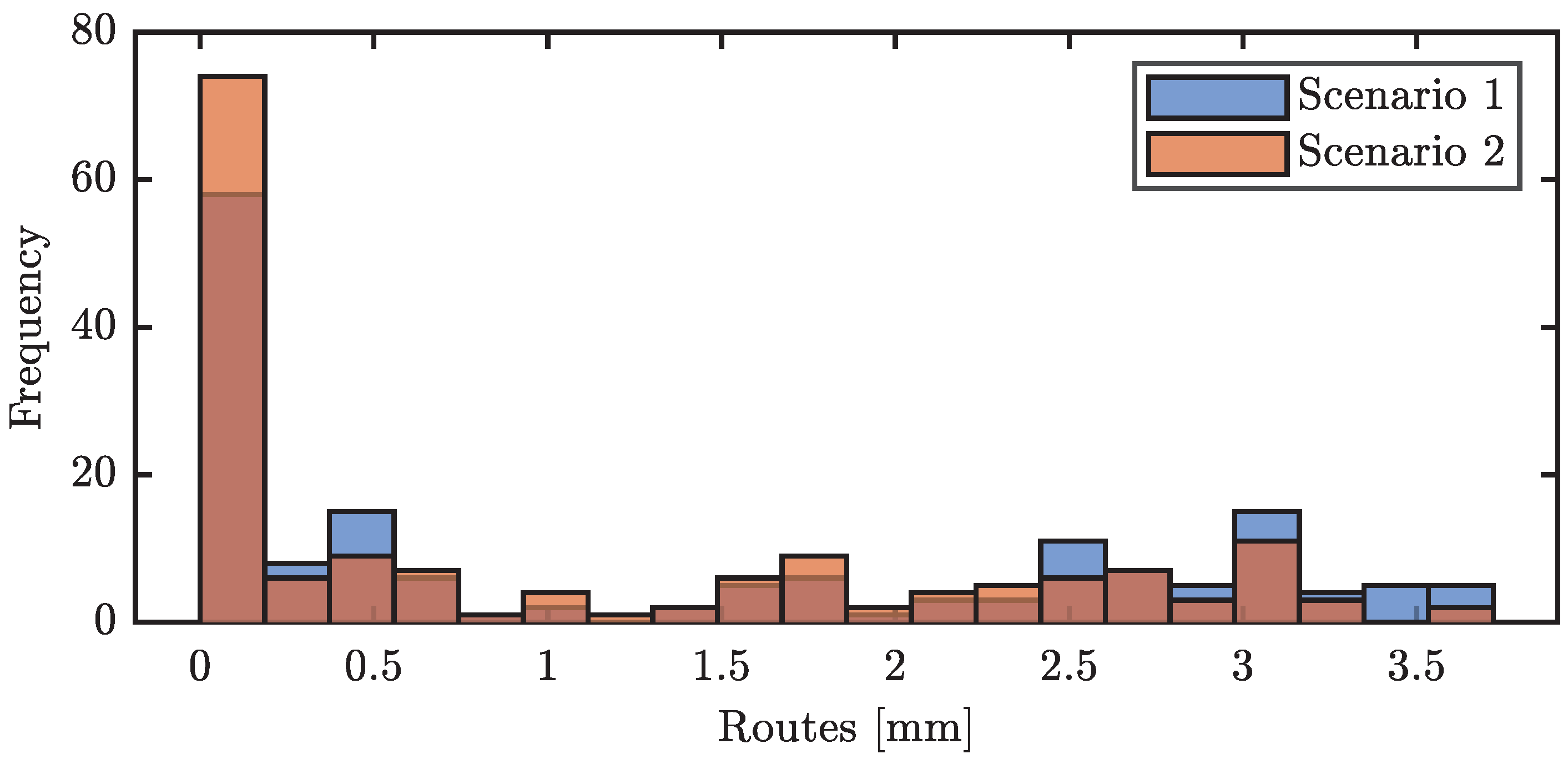
The analysis of the histogram in
Figure 13 provides additional insights into the distribution of the route lengths comparing the two disassembly scenarios. Here, the route lengths were divided into a total of 20 intervals. Scenario 2 shows a higher number of shorter distances compared to scenario 1, which is due to a reduction of tool changes. In scenario 2, the tool change occurs 16 times,
less than in scenario 1. Sections smaller than
occur 74 times in scenario 2,
more than in scenario 1.
Figure 13.
Histogram representing the frequency of routes traveled in the component-oriented (Scenario 1) and accessibility-oriented (Scenario 2) disassembly scenarios.
Figure 13.
Histogram representing the frequency of routes traveled in the component-oriented (Scenario 1) and accessibility-oriented (Scenario 2) disassembly scenarios.
Due to the reduction of tool changes and the associated reduction of the number of routes as well as the minimization of routes with high distances, the disassembly time is reduced by
in scenario 2 compared to scenario 1 from
to
in the reference scenario.
Table 3 summarizes the discussed indicators for comparing component-oriented and accessibility-oriented disassembly.
Table 3.
Indicators for comparing component-oriented and accessibility-oriented disassembly.
Table 3.
Indicators for comparing component-oriented and accessibility-oriented disassembly.
| Indicator |
Sceanrio 1 |
Scenario 2 |
Improvement |
| Tool change [-] |
28 |
16 |
42.9 % |
| Routes [-] |
162 |
138 |
14.8 % |
| Routes smaller than 20 cm [-] |
58 |
74 |
27.6 % |
| Disassembly time [s] |
2224.4 |
1732.2 |
22.1 % |
4.3. Tool Utilization
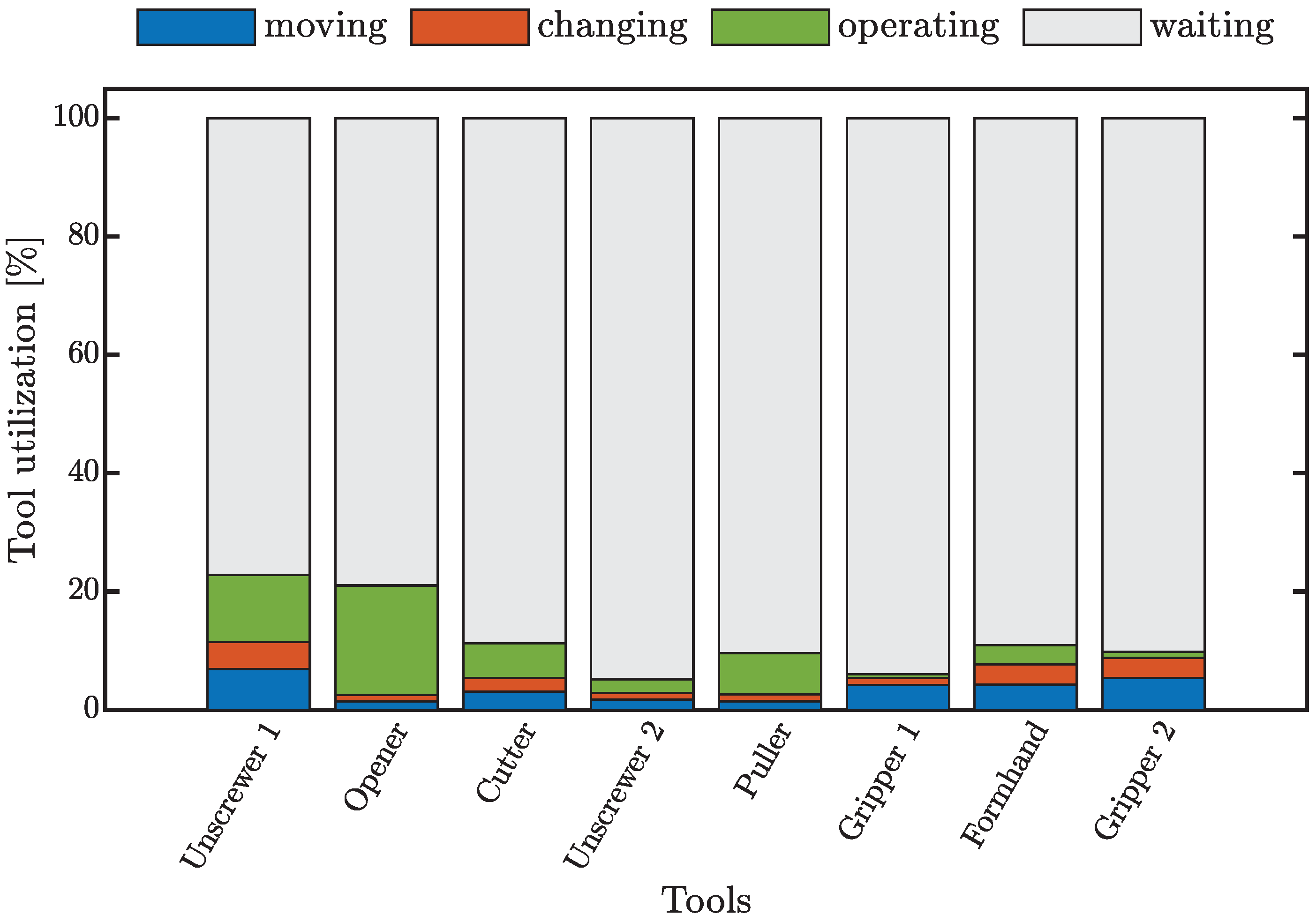
In both scenarios, the utilization of the tools is very low because they can only be used sequentially due to the use of a single manipulator. On average, the tools are in the waiting state for
of the total disassembly time.
Figure 14 shows the tool utilization in the component-oriented disassembly scenario. The accessibility-oriented scenario shows the same trend.
Figure 14.
Tool Utilization during component-oriented disassembly in the reference scenario.
Figure 14.
Tool Utilization during component-oriented disassembly in the reference scenario.
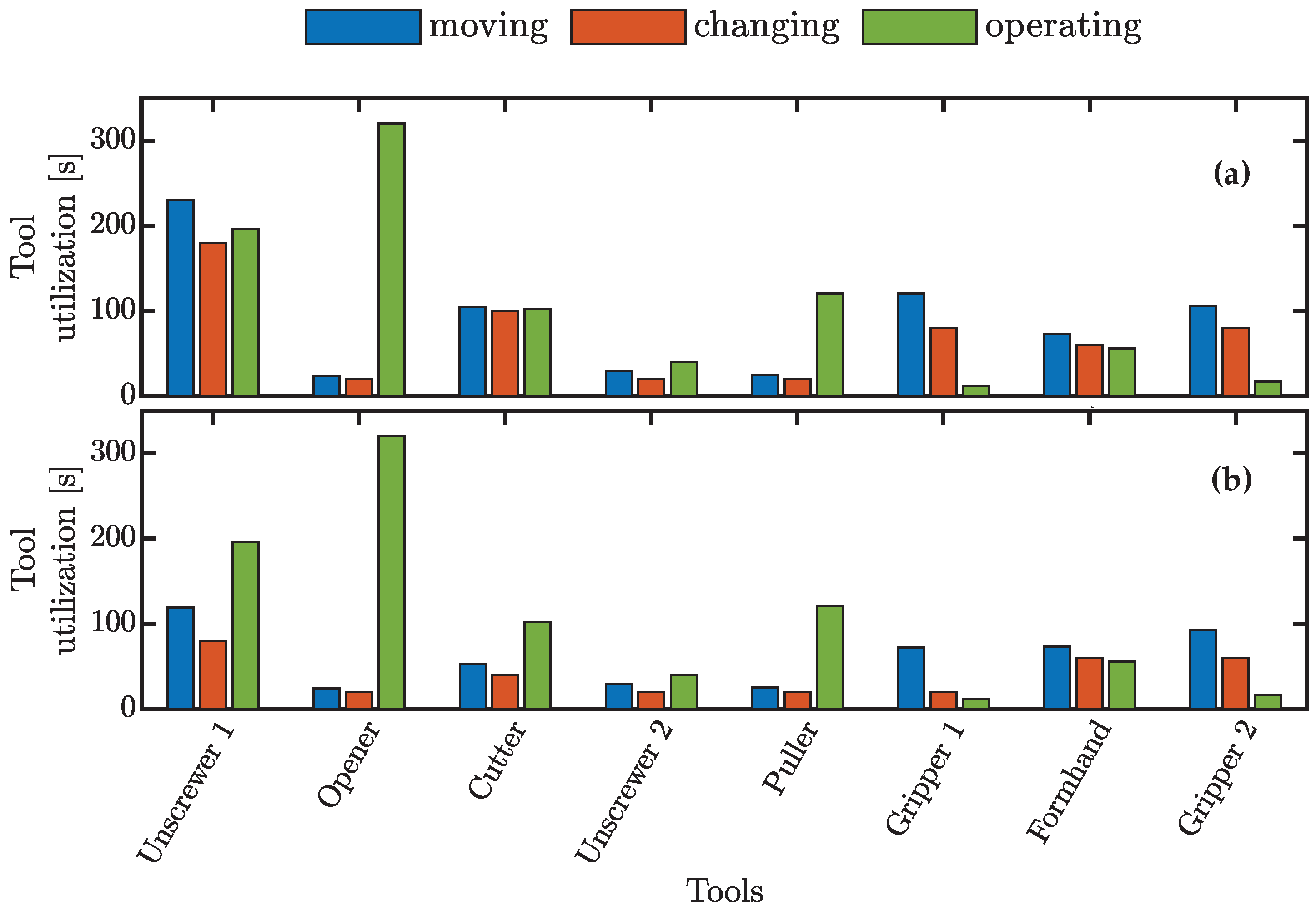
Figure 15 shows a direct comparison between the status of the tools in both scenarios when they are in use. The difference is especially noticeable for tools that are used several times, such as Unscrewer 1. For these tools, the movement and tool change times are halved in the accessibility-oriented scenario compared to the component-oriented scenario.
Figure 15.
State of the disassembly tools and grippers when they are on the robot arm: (a) component-oriented disassembly, (b) accessibility-oriented disassembly.
Figure 15.
State of the disassembly tools and grippers when they are on the robot arm: (a) component-oriented disassembly, (b) accessibility-oriented disassembly.
4.4. Robot Dynamics
The influence of the robot dynamics is considered in the following for the component-oriented disassembly.
Figure 16 on the left shows the dependence of the disassembly time on the velocity of the robot. From
, a strong flattening of the curve can be observed. This can be explained by the fact that from a speed of
, the final speed of the robot is not reached for at least
of the distances to be traveled because the robot starts the braking process before the acceleration phase is completed.
Figure 16 on the right shows the dependence of the disassembly time on the acceleration. An increase in the acceleration does not cause a significant reduction in the disassembly time in the defined reference scenario. This is due to the relatively low final speed of the robot. The acceleration has more influence on the disassembly time the higher the final velocity of the robot is.
Figure 16.
Effect of robot velocity (left) and acceleration (right) on disassembly time in the reference scenario for the component-oriented disassembly.
Figure 16.
Effect of robot velocity (left) and acceleration (right) on disassembly time in the reference scenario for the component-oriented disassembly.
4.5. Positioning of the Battery
The influence of different parameters on the disassembly strategy can be analyzed with the developed model. The battery design, the layout, and relevant process parameters of the disassembly station are considered. Furthermore, it can support the planning of disassembly stations. Particular optimization potential involves positioning various subsystems, such as tools, storage stations, and the processing table. The positioning of these systems in relation to the battery significantly influences the disassembly time.
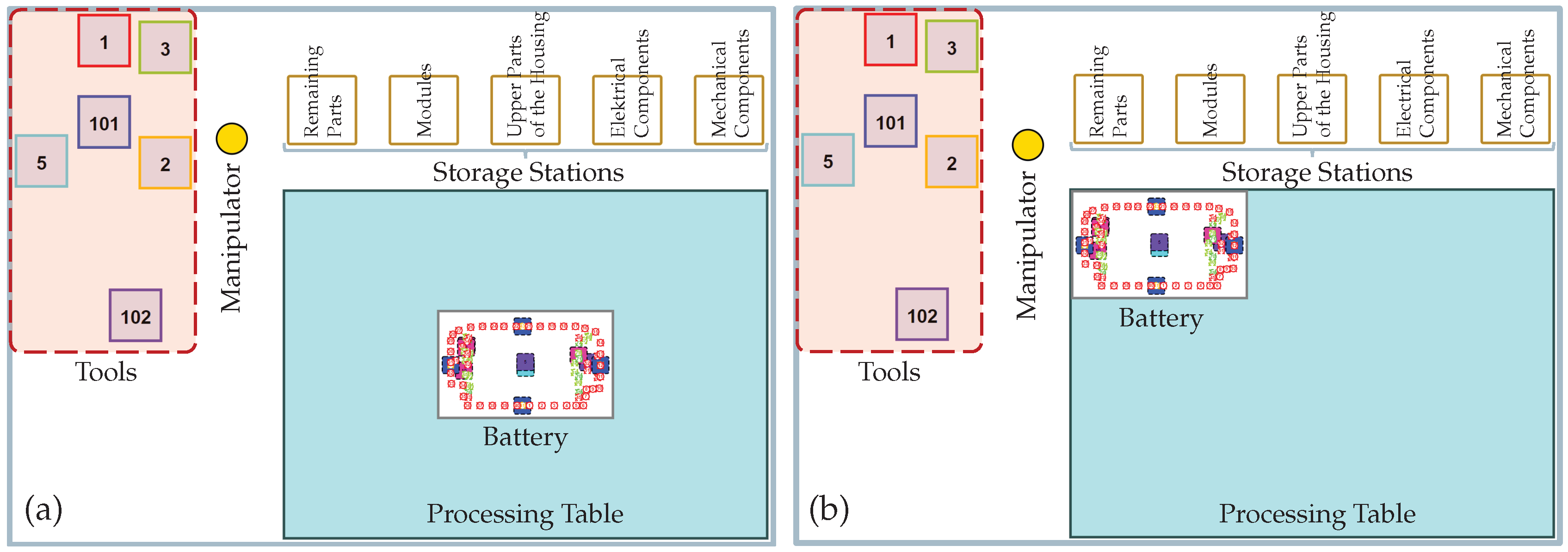
Figure 17 shows screenshots of the investigated disassembly station in the simulation environment.
Figure 17.
Screenshots of the visualization of the battery and the disassembly station in the developed simulation environment. (a) The battery is placed in the center of the processing table. (b) The battery is clamped northwest of the processing table close to the tool station.
Figure 17.
Screenshots of the visualization of the battery and the disassembly station in the developed simulation environment. (a) The battery is placed in the center of the processing table. (b) The battery is clamped northwest of the processing table close to the tool station.
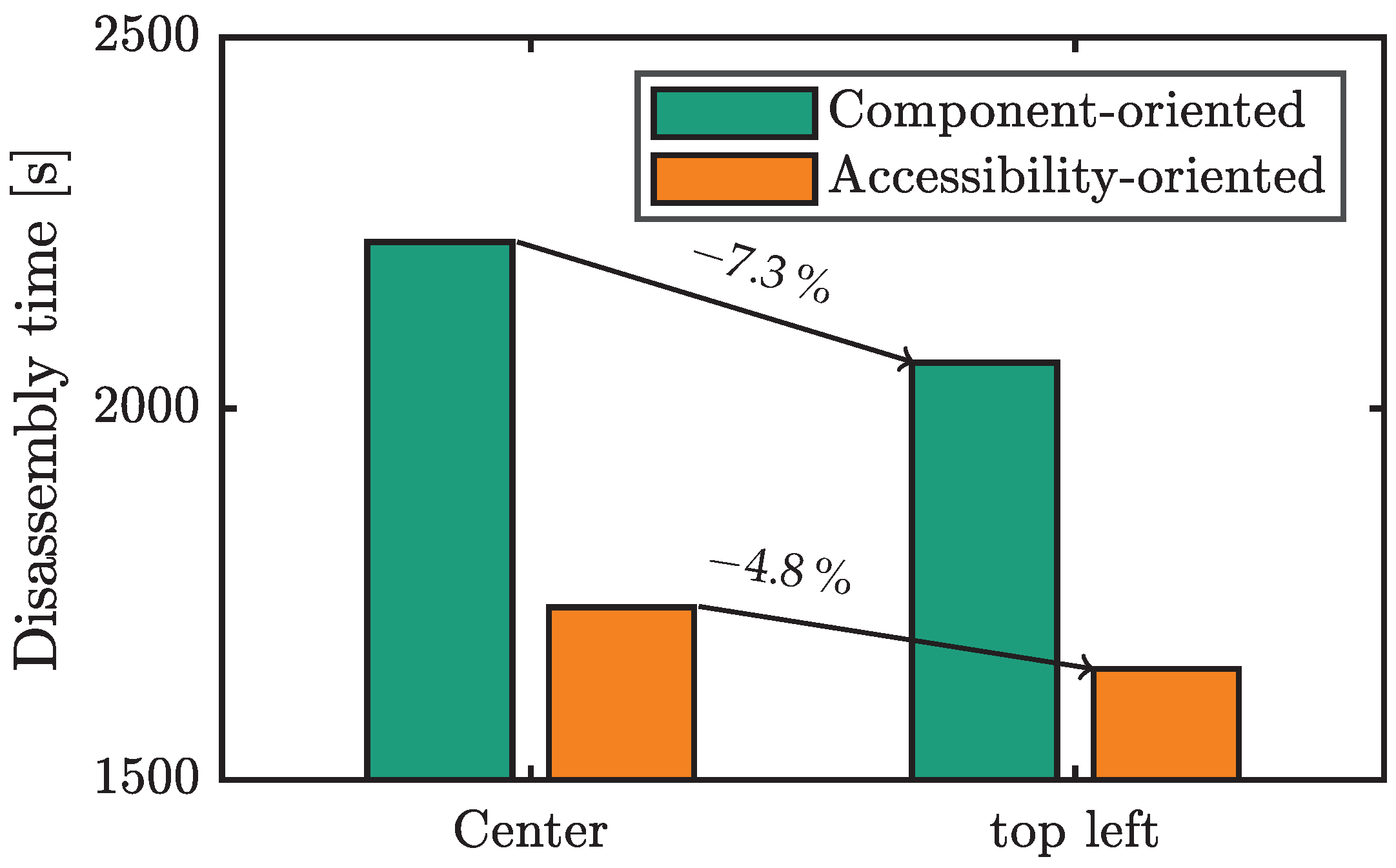
First, the battery is placed in the center of the processing table, as in the reference scenario. Then, the battery is positioned at the top left. This reduces the distances that the robot has to travel, resulting in a reduction of the disassembly time by
(from 2224.4 s to 1732.2 s) in the component-oriented scenario and by
(from 2061.9 s to 1649.2 s) in the accessibility-oriented scenario, see
Figure 18.
Figure 18.
Effect of battery positioning on disassembly times in scenario 1, component-oriented disassembly, and scenario 2, accessibility-oriented disassembly.
Figure 18.
Effect of battery positioning on disassembly times in scenario 1, component-oriented disassembly, and scenario 2, accessibility-oriented disassembly.
5. Discussions
5.1. Discussion of the Methodology
The developed model allows the automatic generation and initialization of simulation models for the investigation of disassembly strategies without having to adapt them specifically to different battery designs or disassembly stations. Nevertheless, the preprocessing phase is time-consuming since the tests have to be performed manually, and the database has to be updated manually. In this context, the automation of preprocessing significantly simplifies the planning and optimization of disassembly strategies for battery systems. This can be achieved, for example, by extracting the required data from CAD models and historical process data.
All necessary data were collected manually for the presented case study, which concerns the battery of Mercedes-Benz AG and the disassembly station at Fraunhofer IPA. The data acquisition was carried out in two-dimensional space. This procedure serves the simplification of the preprocessing and has only a minimal influence on the quality of the results. This is because the battery has a flat design, and the tools are mounted at a similar height as the processing table. When calculating the disassembly distances, the tools’ size was not considered, and direct paths were assumed for the robot routes.
5.2. Discussion of the Results
5.2.1. Disassembly Scenarios
Our results show that accessibility-oriented disassembly has excellent potential to improve the efficiency of the disassembly process compared to component-oriented disassembly. However, it should be noted that this approach may lead to additional computational effort in automated disassembly processes because several components are simultaneously detached and must be gripped and removed. The position of the detached components may change due to gripping operations, which may require re-localization.
5.2.2. Configuration of the Disassembly Station
The low tool utilization and the high number of tool changes show that the layout of the disassembly station in this paper is better applicable for a research and development environment, for example, to test disassembly techniques and tools on various battery designs. More advanced system concepts are needed for industrial applications, such as using multiple robot stations with few tools or using multiple robots to perform parallel disassembly activities in a single disassembly station. The developed model will be extended to model industry-relevant disassembly layouts.
6. Conclusions
An adaptive self-configuring multi-method-simulation model is presented in this paper. The model combines discrete-event simulation with an agent-based approach. The configuration and initialization of the model are carried out automatically using data captured in a preprocessing phase and structured in a database. Furthermore, the simulation model includes a two-step optimization algorithm to optimize the disassembly route while an allocated tool removes a set of connections.
The developed model was demonstrated in a case study using a battery from a plug-in hybrid vehicle of Mercedes-Benz and the disassembly station from the DeMoBat project at Fraunhofer IPA. Two disassembly scenarios were introduced and compared using the simulation model to calculate different indicators: (i) scenario 1: component-oriented disassembly and (ii) scenario 2: accessibility-oriented disassembly. The disassembly time could be reduced by 22.1 % using the accessibility-based disassembly in the defined reference scenario, mainly due to the minimization of the tool change frequency and the reduction of the distances the robot has to travel.
Author Contributions
Conceptualization, S.B.; methodology, S.B.; software, S.B.; validation, S.B.; investigation, S.B.; data curation, S.B.; writing—original draft preparation, S.B.; writing—review and editing, J.G. and K.P.B.; visualization, S.B.; supervision, K.P.B. All authors have read and agreed to the published version of the manuscript.
Funding
The authors wish to thank the Ministry of the Environment, Climate Protection and the Energy Sector Baden-Wuerttemberg for funding this work under the funding code L7520101 as part of the accompanying research of the project DeMoBa. The financial support is gratefully acknowledged.
Data Availability Statement
Most of the data provided in this study are available in the article. Any data not provided can be requested from the authors.
Conflicts of Interest
The authors declare no conflict of interest. The funders had no role in the design of the study; in the collection, analyses, or interpretation of data; in the writing of the manuscript; or in the decision to publish the results.
Appendix A
Figure A1 and
Figure A2 show the disassembly steps of the battery using the component-oriented and the accessibility-oriented disassembly.
Figure A1.
Disassembly steps of the Mercedes-Benz AG battery in the component-oriented disassembly scenario. These are screenshots from the developed simulation environment.
Figure A1.
Disassembly steps of the Mercedes-Benz AG battery in the component-oriented disassembly scenario. These are screenshots from the developed simulation environment.
Figure A2.
Disassembly steps of the Mercedes-Benz AG battery in the accessibility-oriented disassembly scenario. These are screenshots from the developed simulation environment.
Figure A2.
Disassembly steps of the Mercedes-Benz AG battery in the accessibility-oriented disassembly scenario. These are screenshots from the developed simulation environment.
References
- International Energy Agency IEA. World Energy Outlook 2020. Available online: https://www.iea.org/reports/world-energy-outlook-2020 (accessed on 04 October 2023).
- European Parliament. Deal confirms zero-emissions target for new cars and vans in 2035. Available online: https://www.europarl.europa.eu/news/en/press-room/20221024IPR45734/deal-confirms-zero-emissions-target-for-new-cars-and-vans-in-2035 (accessed on 04 October 2023).
- International Energy Agency IEA. Global EV Outlook 2023. Available online: https://www.iea.org/reports/global-ev-outlook-2023 (accessed on 04 October 2023).
- Agora Verkehrswende. Klimabilanz von Elektroautos: Einflussfaktoren und Verbesserungspotenzial. Available online: https://www.agora-verkehrswende.de/en/publications/lifecycle-analysis-of-electric-vehicles-study-in-german-with-english-executive-summary/ (accessed on 04 October 2023).
- Chair of Production Engineering of E-Mobility Components PEM of RWTH Aachen University, Battery LabFactory Braunschweig, Mechanical Engineering Industry Association VDMA. Recycling of Lithium-Ion Batteries. Available online: https://www.vdma.org/c/document_library/get_file?uuid=479ae54b-5b43-cfff-df4f-f359e79c8eb5&groupId=34570 (accessed on 04 October 2023).
- Yun, L.; Linh, D.; Shui, L.; Peng, X.; Garg, A.; Phung LE, M.L.; Asghari, S.; Sandoval, J. Metallurgical and mechanical methods for recycling of lithium-ion battery pack for electric vehicles. Resources, Conservation and Recycling 2018, 136, 198–208. [Google Scholar] [CrossRef]
- Al Assadi, A.; Goes, D.; Baazouzi, S.; Staudacher, M.; Malczyk, P.; Kraus, W.; Nägele, F.; Huber, M.F. ; Fleischer,J.; Peuker, U.; Birke, K.P. Challenges and prospects of automated disassembly of fuel cells for a circular economy. Resources, Conservation & Recycling Advances 2023, 19. [Google Scholar] [CrossRef]
- Gerlitz, E.; Greifenstein, M.; Kaiser, J.P.; Mayer, D.; Lanza, G.and Fleischer, J. Systematic Identification of Hazardous States and Approach for Condition Monitoring in the Context of Li-ion Battery Disassembly. Procedia CIRP 2022, 107, 308–313. [Google Scholar] [CrossRef]
- Xiao, J.; Jiang, C.; Wang, B. A Review on Dynamic Recycling of Electric Vehicle Battery: Disassembly and Echelon Utilization. Batteries 2023, 9, 57. [Google Scholar] [CrossRef]
- Huster, S.; Glöser-Chahoud, S.; Rosenberg, S. and Schultmann, F. A simulation model for assessing the potential of remanufacturing electric vehicle batteries as spare parts. Journal of Cleaner Production 2022, 363. [Google Scholar] [CrossRef]
- Liang, X.; Jin, X. and Ni, J. Forecasting product returns for remanufacturing systems. Journal of Remanufacturing 2014, 4. [Google Scholar] [CrossRef]
- Mete, S.; Abidin Çil; Z., Özceylan, E and Ağpak, K. Resource Constrained Disassembly Line Balancing Problem. IFAC-PapersOnLine 2016, 49, 921–925. [CrossRef]
- Yuanjun Laili, Yulin Li, Yilin Fang, Duc Truong Pham, Lin Zhang. Model review and algorithm comparison on multi-objective disassembly line balancing. Journal of Manufacturing Systems 2020, 56, 484–500. [CrossRef]
- Tang, Y.; Zhou, M.; Gao, M. Fuzzy-Petri-net-based disassembly planning considering human factors. IEEE Transactions on Systems, Man, and Cybernetics-Part A: systems and humans 2006, 36, 718–726. [Google Scholar] [CrossRef]
- McGovern, S.M. and Gupta, S.M. Ant colony optimization for disassembly sequencing with multiple objectives. The International Journal of Advanced Manufacturing Technology 2006, 30, 481–496. [CrossRef]
- Ren, Y.; Tian, G.; Zhao, F.; Yu, D. and Zhang, C. Selective cooperative disassembly planning based on multi-objective discrete artificial bee colony algorithm. Engineering Applications of Artificial Intelligence 2017, 64, 415–431. [CrossRef]
- Zhou, Z.; Liu, J.; Pham, D.T.; Xu, W.; Ramirez, F J.; Ji, C. and Liu, Q. Disassembly sequence planning: Recent developments and future trends. In Proceedings of the Institution of Mechanical Engineers, Part B: Journal of Engineering Manufacture; 2019; Volume 233, pp. 1450–1471. [CrossRef]
- Choux, M.; Marti Bigorra,E.; Tyapin, I. Task Planner for Robotic Disassembly of Electric Vehicle Battery Pack. Metals 2021, 11, 387. [CrossRef]
- Wegener, K.; Andrew, A.; Raatz, A.; Dröder, K.; Herrmann, C. Disassembly of Electric Vehicle Batteries Using the Example of the Audi Q5 Hybrid System. Procedia CIRP 2014, 23, 155–160. [Google Scholar] [CrossRef]
- Alfaro-Algaba, M.; Ramirez, F.J. Techno-economic and environmental disassembly planning of lithium-ion electric vehicle battery packs for remanufacturing. Resources, Conservation and Recycling 2020, 154, 104461. [CrossRef]
- Ke, Q.; Zhang, P.; Zhang, . and Song, S. Electric vehicle battery disassembly sequence planning based on frame-subgroup structure combined with genetic algorithm. Frontiers in Mechanical Engineering 2020, 6. [CrossRef]
- Xiao, J; Anwer, N.; Li, W.; Eynard, B.; Zheng; C. Dynamic Bayesian network-based disassembly sequencing optimization for electric vehicle battery. CIRP Journal of Manufacturing Science and Technology 2022, 38. [CrossRef]
- Baazouzi, S.; Rist, F. P.; Weeber, M. and Birke, K. P. Optimization of disassembly strategies for electric vehicle batteries. Batteries 2021, 7, 74. [Google Scholar] [CrossRef]
- Guo, X.; Zhou, M.; Abusorrah, A.; Alsokhiry, F.; Sedraoui, K. Disassembly sequence planning: a survey. IEEE/CAA Journal of Automatica Sinica 2020, 8, 1308–1324. [Google Scholar] [CrossRef]
- Borshchev, A. The big book of simulation modeling: multimethod modeling with AnyLogic 6; AnyLogic North America: Chicago, 2013. [Google Scholar]
- Process Modeling Library. Available online: https://www.anylogic.com/features/libraries/process-modeling-library/ (accessed on 04 October 2023).
- Larrañaga, P., Kuijpers, C., Murga, R. et al. Genetic algorithms for the travelling salesman problem: A review of representations and operators. Artificial intelligence review 1999, 13, 129–170. [CrossRef]
- Hougardy, S.; Wilde, M. On the nearest neighbor rule for the metric traveling salesman problem. Discrete Applied Mathematics 2015, 195, 101–103. [Google Scholar] [CrossRef]
- Croes G., A. A method for solving traveling-salesman problems. Operations research 1958, 6(6), 791–812. [Google Scholar] [CrossRef]
- Mercedes-Benz Group. No compromise: The plug-in hybrid technology. Available online: https://group.mercedes-benz.com/company/magazine/technology-innovation/easy-tech-plug-in-hybrid-technology.html (accessed on 04 October 2023).
- Rosenberg, S.; Huster, S.; Baazouzi, S.; Glöser-Chahoud, S.; Al Assadi, A.; Schultmann. F. Field Study and Multimethod Analysis of an EV Battery System Disassembly. Energies 2022, 15, 5324. [CrossRef]
- Fraunhofer Institute for Manufacturing Engineering and Automation IPA. Industrial disassembly of battery modules and electric motors. Available online: https://www.ipa.fraunhofer.de/en/reference_projects/DeMoBat.html (accessed on 04 October 2023).
- Fraunhofer Institute for Manufacturing Engineering and Automation IPA. Robot-based dismantling of e-vehicle batteries. Available online: https://www.youtube.com/watch?v=wtR413ipMtQ (accessed on 04 October 2023).
- FORMHAND Automation GmbH. Geometry-independent gripping. Available online: https://www.formhand.de/en/products/gripping (accessed on 04 October 2023).
|
Disclaimer/Publisher’s Note: The statements, opinions and data contained in all publications are solely those of the individual author(s) and contributor(s) and not of MDPI and/or the editor(s). MDPI and/or the editor(s) disclaim responsibility for any injury to people or property resulting from any ideas, methods, instructions or products referred to in the content. |
© 2023 by the authors. Licensee MDPI, Basel, Switzerland. This article is an open access article distributed under the terms and conditions of the Creative Commons Attribution (CC BY) license (http://creativecommons.org/licenses/by/4.0/).

