1. Introduction
The continuous development of unmanned underwater vehicles (UUVs) has led to their increasing utilization in various demanding underwater tasks in recent years. In the field of offshore infrastructure inspection, UUVs have proven their effectiveness in applications like inspecting underwater bridge substructures [
1] and pipeline inspection [
2]. UUVs also play a significant role in mapping and exploration in extreme environments, such as mapping the seafloor in ice-covered waters [
3], mapping shipwrecks [
4], and conducting hyperspectral imaging of Arctic macroalgal habitats [
5]. Furthermore, specialized UUVs with unique structures and actuators have been developed for specific underwater operations. Examples include the addition of a crawling skid to an UUV for underwater maintenance tasks [
6], the development of a prototype UUV for marine-growth removal [
7], and the establishment of an underwater manipulator for delicate repair operations [
8]. These vehicles have proven instrumental in replacing humans for hazardous and labor-intensive underwater work, effectively reducing operational costs and associated risks. Currently, the primary focus of development is achieving autonomy for underwater vehicles, enabling them to make decisions and perform tasks without constant human intervention. With a higher level of autonomy, UUVs offer several advantages such as the ability to carry out maritime missions over long distances or in hazardous areas.
The challenges in designing control systems for UUVs arise from their parametric uncertainties and unpredictable environmental disturbances. Various control strategies have been applied to UUVs. Proportional–integral–derivative (PID) control is a commonly used controller in UUV control strategies, which demonstrates robustness, easy implementation, and ability to addresses parametric uncertainty issues due to its model-free nature [
9]. Numerous PID controllers have been developed and implemented for UUVs, such as the fractional-order PID controller that optimizes parameters respect to the parameter uncertainties[
10], thw adaptive fuzzy nonlinear PID controller that provide robustness against external disturbances [
11], and the intelligent-PID with PD feedforward, which further enhances stability [
12]. Sliding mode control (SMC) becomes a widely used nonlinear control method in UUV motion control [
13], which proves effective in handling systems with uncertainties, disturbances, and nonlinearities. A dual closed-loop integral SMC method has been developed for controlling underactuated UUVs [
14]. This approach effectively handles the nonlinear and coupled behaviors of the vehicle, making it suitable for three-dimensional underactuated scenarios. A sliding mode based fault tolerant control method integrated with thrust allocation has also been proposed to reduce the steady error caused by thruster faults [
15]. However, SMC suffers from the chattering problem caused by its discontinuous control law when the vehicle moves at high speeds, leading to decreased accuracy and energy loss.
Neural Network (NN)-based control methods, as a type of adaptive control technique, also effectively address parametric uncertainties by learning and adapting to changing environments or system dynamics. Unlike traditional methods, NN-based control approximates system dynamics using NNs and adjusts network parameters in real-time based on data and feedback. This adaptability enables the control system to handle variations, uncertainties, and disturbances, enhancing robustness and flexibility. Moreover, NN-based control excels in managing complex and nonlinear systems by capturing intricate patterns and relationships, ensuring accurate control in highly uncertain scenarios. A hybrid coordination method that uses reinforcement learning to learn system behavior online was implemented in an AUV [
16]. A robust neural network approximation-based output-feedback tracking controller has also been proposed to effectively compensate for uncertainties [
17]. However, the system stability of NN-based control methods is often challenging to theoretically prove. Thus, the validation of the control system typically relies on experimental evidence. Furthermore, the effectiveness of the neural network adaptive controller relies significantly on the quantity of neural network nodes, leading to a substantial computational burden that hinders its practical implementation in engineering applications.
Disturbance observer-based control (DOBC) is a control technique that aims to address the challenges posed by environmental disturbances in a control system. It involves the estimation and compensation of disturbances to improve the system’s overall performance and robustness. In contrast to other approaches that deal with disturbances by designing robust controllers, as mentioned earlier, DOBC ensures that the performance of the outer-loop controller is not degraded when disturbances are estimated in the inner loop. A nonlinear disturbance observer (NDO) was designed and incorporated into nonsingular fast terminal sliding mode control scheme for trajectory tracking of an under-actuated UUV [
18]. This incorporation guarantees finite-time convergence and demonstrates improved immunity to external disturbances. An implementation of a disturbance observer has been incorporated into fuzzy adapted S-Surface control to improve robustness against unmodelled disturbances [
19].
Although the methods mentioned earlier are capable of mitigating external disturbances and unmodelled uncertainty to a certain degree, they possess certain limitations. In the case of DOBC methods, most of them have assumption of zero measurement noise, which is unrealistic in practical marine robotic systems. On the other hand, control methods such as SMC and NN-based adaptive control can address measurement noise, but they introduce issues of their own, such as chattering and high computational complexity. Furthermore, when designing a viable control system for UUVs, it is essential to account for system input and state constraints.
Model Predictive Control (MPC) is a control strategy that involves solving an optimal control problem (OCP) with a finite horizon recursively to determine the control action. This approach ensures that the system constraints are consistently considered throughout the control process [
20]. As a result, MPC has gained significant interest in marine robotics due to its capability to handle control limits, control variation bounds, and state constraints. The application of MPC to marine vessels for dynamic positioning was demonstrated in [
21]. The study showed that implementing MPC allows for the distribution of force generation over a specific time period and enables the planning of vessel motion based on the varying configuration of the rotable thrusters. Nonlinear Model Predictive Control (NMPC) has also been developed to enable an AUV to follow predefined trajectories in the water column [
22], showcasing the potential for real-time MPC control with in situ estimated water current profiles. Furthermore, a Lyapunov-based MPC has emerged in recent years to ensure closed-loop stability [
23]. The robustness of NMPC for UUV motion control has been experimentally validated in a water tank capable of generating directional ocean currents [
24]. These MPC-based studies have effectively demonstrated the advantages of using MPC in UUV motion control through numerical simulations and experiments. Recently, MPC based on the active disturbance rejection control (ADRC) was also proposed for motion control of an AUV [
25]. This method incorporates a discrete extended state observer to estimate disturbances and applies feedback control to compensate for them. By combining the strengths of MPC and DOBC, the controller can effectively handle parametric uncertainties and external disturbances in the inner loop. Meanwhile, MPC can address system constraints in the outer loop. Therefore, by further developing a suitable disturbance observer that is robust against measurement noise, a feasible and efficient control system for UUVs can be ensured.
Motivated by aforementioned considerations, an extended active observer (EAOB) is developed using the extended Kalman Filter (EKF) to integrate with MPC and form the disturbance observer-based MPC (DOBMPC) in this work. The significant contribution of the designed EAOB lies in its capability to estimate disturbances in the presence of measurement noise. Additionally, the unmodeled parameter in the MPC’s prediction model is considered part of the disturbance term, effectively addressing the issue of parametric uncertainty. Unlike the conventional approach of compensating estimated disturbances into control inputs, the estimated disturbances are incorporated into the MPC’s prediction model and updated at each time step. This allows the MPC to generate an optimal control law while taking disturbances into account. The proposed control method aims to achieve the following objectives:
Mitigate disturbances, including environmental disturbances, unmodeled dynamics, and measurement noises.
Perform real-time disturbance estimation and incorporate the estimated disturbances into the MPC’s prediction model at each time step, resulting in a parameter-varying model.
Incorporate the estimated disturbances into the MPC’s prediction horizon to enable the generation of optimal control inputs for effective disturbance rejection.
Ensure that system input and state constraints are taken into account during optimizations.
The structure of the paper is outlined as follows.
Section 2 describes the dynamic model of the UUV.
Section 3 explains the design of the proposed EAOB.
Section 4 covers the implementation of the entire DOBMPC system.
Section 5 showcases and discusses the results obtained from employing the proposed DOBMPC for dynamic positioning and trajectory tracking. Lastly,
Section 6 summarizes the research work and outlines future directions.
2. Problem Formulation
In this research work, we selected BlueROV2 [
26] which has 4 degrees of freedom as the UUV platform. Its motion encompasses surge, sway, heave, and yaw. Fossen’s theory [
27] is employed to model the motion of UUV, which includes both rigid body and added mass. This section provides detailed explanations of the kinematic and kinetic equations governing UUV motion. These equations serve as the foundation for establishing a system model for motion control. The notations of parameters obtained in the UUV dynamic model are summarized in
Table 1.
Table 1.
Notations in the UUV dynamic model.
Table 1.
Notations in the UUV dynamic model.
| |
Surge Sway Heave |
Roll Pitch Yaw |
| Position
|
x y z (m) |
() |
| Velocity
|
u v w () |
p q r () |
| Forces and Moments
|
X Y Z (N) |
K M N () |
| Control Inputs
|
(N) |
/ / () |
| Disturbances
|
(N) |
() |
| Added Mass |
() |
() |
| Linear Damping |
() |
() |
| Nonlinear Damping |
() |
() |
2.1. Kinematic Model
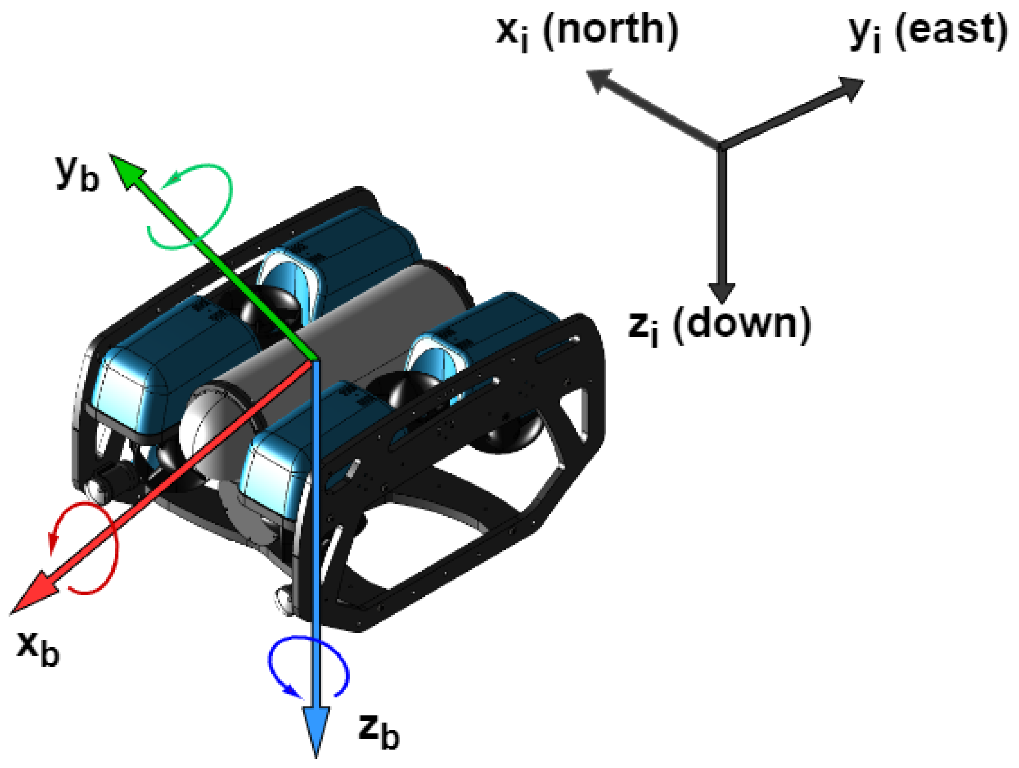
The UUV’s motion states are described using two reference frames: the body-fixed reference frame (BRF) and the inertial reference frame (IRF). The BRF is fixed to the vehicle, with the center of gravity serving as the origin, and the body axes aligned with the principal axes of inertia. The longitudinal axis, denoted as the
, extends from aft to fore. The transversal axis, referred to as the
, extends from port to starboard. Per the right-hand rule, the
axis is perpendicular to both the
and
axes. The UUV’s motion is characterized as the motion of the BRF relative to the IRF. The IRF is employed to track the vehicle’s trajectory and define the control objectives. In this work, the IRF is aligned with the north-east-down (NED) coordinate system. This choice is motivated by the prevalence of expressing position vectors in NED coordinates within various navigation applications and simulation environments. The axes in IRF are denoted as
,
, and
, as shown in
Figure 1.
Figure 1.
The reference frames of the UUV.
Figure 1.
The reference frames of the UUV.
In the UUV’s model states, the linear and angular velocities are described in the BRF as
, while the linear and angular position are expressed in the IRF as
. Since the velocity vector and position vector are expressed in different reference frames, the rotation matrix
are required for describing the relationship between them. Let
represents the linear velocity in BRF,
represents the linear velocity in IRF. thus, the
and
can be related by equation:
where
includes the Euler angles (roll
, pitch
and yaw
). Then the rotation matrix can be computed based on
as:
For the transformation of angular states, let
represents angular velocity in the BRF relative to the IRF then:
where
is the Euler angle rate. The transformation matrix
which represents the relationship between angular states in the BRF and IRF can be expressed as:
Therefore, the relationship between UUV’s velocity and position is given by:
where
represents the linear position of UUV in the IRF.
2.2. Kinetic Model
To simplify the process of deriving the dynamic equations for UUV motion, it is common to assume that the vehicle behaves as a rigid body. This assumption eliminates the need to analyze the interactions between individual mass elements. The overall dynamic model can be expressed as follows:
where
is the mass matrix,
is the Coriolis and centripetal matrix,
is the hydrodynamic damping matrix,
is the vector of the gravitational and buoyancy forces, the
is the total propulsion forces and moments, and
is the external disturbance. The
M and
contain terms for both the rigid body and hydrodynamic added mass as:
2.2.1. Rigid-body dynamics
By using Newtonian physics, the rigid-body dynamics of the UUV, may be deduced as follows:
Assuming that the origin of the BRF is positioned at the geometric center of the UUV and the vehicle exhibits symmetry in both the port-starboard and fore-aft plane, the rigid-body mass matrix can be simplified. As a result, the rigid-body mass
can be expressed as:
where
m is the mass of the vehicle,
,
and
are the inertia moments about the
,
, and
axes in BRF, measured in
;
is the position of the CG in relation to the centre of the vehicle in
axis, measured in meters. Subsequently, using the skew-symmetric cross-product operation on
yields the result of the rigid-body Coriolis and centripetal matrix
is given by:
2.2.2. Hydrodynamics
The hydrodynamics studied in this work encompass both hydrodynamic added mass and hydrodynamic damping. Hydrodynamic added mass can be perceived as a virtual mass that is introduced to a system when a body accelerates or decelerates, requiring the movement of a certain volume of the surrounding fluid. This concept is formulated based on Kirchhoff’s equation.
In an ideal fluid, for a rigid body that is either at rest or moving at a forward speed
, the hydrodynamic system inertia matrix
is positive semi-definite. The hydrodynamic coefficients are defined as the partial derivatives of the added mass force with respect to the corresponding acceleration. In many practical applications, the non-diagonal elements of
are significantly smaller than the diagonal elements. As a result, the off-diagonal terms of
can be disregarded, leading to a simplified form of
as follows:
Accordingly, the nonlinear hydrodynamic Coriolis and centripetal matrix
can be calculated as:
The primary components of hydrodynamic damping for UUVs are potential damping, skin friction, wave drift damping, and damping caused by vortex shedding. Typically, potential damping and wave drift damping are disregarded in UUVs model. These various damping factors contribute to both linear and quadratic damping, as follows:
The linear damping term (
) is a result of skin friction, while the nonlinear damping matrix (
) is caused by quadratic damping and higher-order terms. Due to decoupling, the damping matrix is derived to be diagonal. As a result, the linear damping matrix is represented by Equation
15, and the quadratic damping matrix is represented by Equation
16.
2.2.3. Hydrostatics
Archimedes [
28] established the foundational principles of fluid statics, which form the basis of hydrostatics today. Considering the mass of the UUV as
m that measured in
, acceleration due to gravity as
g, water density as
that measured in
, and the volume of fluid displaced by the UUV as
∇ that measured in
. Therefore, the weight of the UUV can be expressed as
, while the buoyancy force
B is expressed as
.
Given the center of buoyancy of the UUV is
. Assume the centre of the vehicle’s body frame is placed at the center of buoyancy (CB), then
. Since the vehicle has symmetry in the xz-plane and xy-plane, the position of the CG of the vehicle
becomes
. Thus, the overall restoring force vector
can be calculated using Euler angle transformation as:
2.2.4. Propeller Model and Control Allocation
A realistic model of the propeller is taken into account in the dynamic model of the UUV. The control inputs, denoted as
, where
,
,
,
correspond to the forces and moments in the surge, sway, heave, and yaw directions of the UUV, respectively. The BlueROV2 is equipped with six propellers to facilitate movement in 4 degrees of freedom, resulting in an over-actuation scenario. Hence, the control inputs
u are allocated to each propeller using the control allocation matrix. The thrust vector, represented as
, is determined as follows:
where
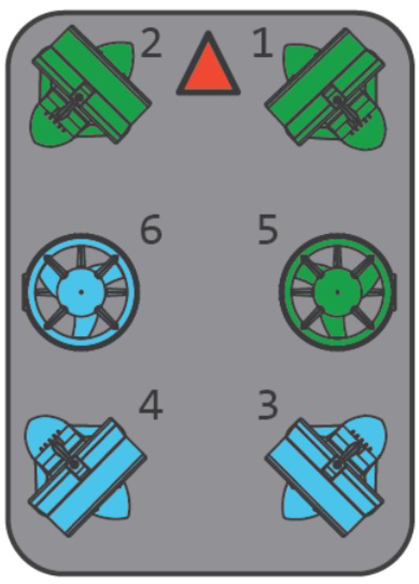
t is the thrust produced by all propellers, and the layout of six propellers is shown in
Figure 2. The blue propellers rotate clockwise, the green propellers rotate counterclockwise, and the red arrow indicates the positive surge direction.
Figure 2.
The propeller configuration of the BlueROV2, propeller 1, 2, 3, and 4 provide thrust in x-y plane, while propeller 5 and 6 provide thrust in vertical direction.
Figure 2.
The propeller configuration of the BlueROV2, propeller 1, 2, 3, and 4 provide thrust in x-y plane, while propeller 5 and 6 provide thrust in vertical direction.
The propulsion matrix, denoted as
K, is utilized to calculate the combined force and moment that propel the UUV. This matrix represents the spatial distribution of propellers on the BlueROV2’s structure:
For calculating the propulsion matrix, given that
is the distance between the centre of propeller
i and the CG in
direction, and
is the force projection to x direction, therefore, the forces and moments produced by propeller 1 are:
where
denotes the angle at which the propeller is positioned with respect to the UUV’s forward direction, measured in radians. Using the value
and
,
,
for propeller 1. Therefore, the first column in K can be obtained. The rest column can be calculated in the same way, thus the propulsion matrix becomes:
2.2.5. Nonlinear Model
In summary, for achieving motion control of the UUV, the system state is defined as
. From the Equation
5 and Equation
7, the general form of the UUV is obtained as:
3. Extended Active Observer
When designing control systems, it is often customary to apply the principle of superposition when accounting for wave
and current disturbance
[
27]. The disturbance term also encompasses unmodeled dynamics
, such as uncertainties related to rigid-body parameters (e.g., inertia and mass properties) and hydrodynamic parameters (e.g., hydrodynamic damping force) that are challenging to accurately identify. This principle implies that all sources of disturbances are combined and included on the right-hand side of Equation
22 as the disturbance term
,
Assumption 1: It is assumed that the disturbance caused by ocean waves () and currents (), as well as the uncertainty in unmodeled dynamics (), are bounded, specifically by , , . , , and are unknown positive constants to be estimated. As a result, the total disturbance is bounded by the sum of these limits, i.e., .
Assumption 2: It is assumed that the total disturbance is low time-varying signal.
Therefore, the internal disturbance model can be constructed as:
3.1. Observer Design
For using EKF to construct disturbance observer to compensate the unpredictable uncertainties, the disturbance term is considered as system states along with the position and velocity .
In real-world scenarios, it is common for the system being modeled to exhibit continuous-time dynamics, while measurements are obtained at discrete time intervals. To address this problem, the continuous-discrete EKF (CD-EKF) is employed for constructing the EAOB. The CD-EKF incorporates both continuous and discrete dynamics into the estimation process, operating similarly to the standard EKF but with the additional capability of handling discrete dynamics. The continuous dynamics are typically described using differential equations, while the discrete dynamics are represented by difference equations. During the prediction step of the CD-EKF, the continuous dynamics are discretized by integrating forward in time using numerical integration techniques, effectively capturing the system’s continuous evolution between measurement updates. In the update step, the CD-EKF incorporates the discrete-time measurements to correct and refine the state estimate. By seamlessly combining both continuous and discrete dynamics within the estimation process, the CD-EKF offers improved accuracy and robustness in estimating the state variables of systems with mixed dynamics. Therefore, the system process is represented as continuous-time model, while the discrete-time measurements are taken. The system process model can be reconstructed as:
where measurement states
,
refers to the process noise that is assumed to be zero mean Gaussian noise with covariance
, and
refers to the nonlinear system process model.
Therefore, the system process model can be formulated based on the UUV’s model in Equation
22:
The measurement states contain the position
, velocity
and propulsion forces and moments
, thus the discrete-time measurement model is formulated as:
where measurement states
,
is the measurement noise which is assumed to be zero mean Gaussian noise with covariance
, and
refers to the nonlinear measurement model that relates the system states to the measurements obtained from sensors. The first 12 terms of the measurement model are identity to the system process model, and the
can be calculated base on disturbance term
as:
The accurate estimation of solutions heavily relies on the design of the noise covariance matrices for the system process
and measurements
. One approach to construct
is by utilizing the piecewise white noise model (PWNN). This stochastic model allows for the representation of varying noise characteristics across different time intervals or regions. By incorporating PWNN, the time-varying dynamics of the system can be more precisely captured in the EKF. This is particularly beneficial when dealing with systems that exhibit non-stationary or changing noise characteristics. The equation for calculating the system process noise covariance
based on PWNN is as follows:
where
is the noise gain of the system,
is the sampling time step, and
represents the variance of the white noise process. The covariance of the measurement noise
is also dependent on the sampling time step
, which is defined as:
The system process model
and the measurement model
can be linearized by taking the partial derivatives of each to evaluate the state transition matrix
and the measurement matrix
at each operating point with Jacobian matrix. The state transition matrix
which describes the relationship between the current state and the next predicted state in a dynamic system is obtained as the Equation
31, and the measurement matrix
relates the measurements obtained from sensors to the predicted state of the system is formulated as the Equation
32.
Denote the three elements in the second row of matrix
as
,
, and
. Therefore
The CD-EKF is a recursive estimation algorithm, where the main procedure can be divided into prediction and update parts. Before starting the recursion, an initialization step is performed based on the first measurement:
In the prediction part, it predicts the state estimate
based on the previous state estimate and the system dynamics. Then the error covariance matrix
can be calculated based on the state transition matrix
. The prediction part is shown as follows:
In Equation 35, a numerical integration method should be applied for discretization of continuous-time system process model. Various ways of discretization in EKF have been discussed [
29]. In this work, the continuous dynamics of the system is approximated using a deterministic integration scheme. This scheme yields a deterministic estimation of the system’s behavior between measurement updates, assuming no uncertainty or stochasticity in the system dynamics. Deterministic integration methods are preferred due to their computational efficiency, avoiding the computational burden associated with simulating random processes. Specifically, the fourth-order Runge-Kutta (RK4) method is selected for its superior accuracy and stability compared to lower-order integration methods like Euler’s method or the second-order Runge-Kutta method. The RK4 method achieves this by evaluating the system dynamics at multiple intermediate points during each integration step, resulting in a more precise estimation of the state variables. The process of RK4 can be described by the following equations:
In the update part, it calculates the measurement residual
with current measurements
and measurement model. Then the Kalman Gain
at time
k can be determined based in the predicted error covariance matrix
and linearized measurement matrix
. Finally, it updates the state estimate
based on the predicted state estimate
and the Kalman Gain
, and recalculate the error covariance matrix
based on Kalman Gain
and the linearized measurement model
. The following equations express the procedure in EKF’s update part
3.2. Stability Analysis
The stability of using the EKF for force estimation has been demonstrated in [
30]). Accordingly, the stability analysis of the proposed EAOB method can be conducted using two theorems.
Theorem 1. The proposed EAOB for the system described in Equation 22 is locally stable, given that
Theorem 2. Assume that the model of a linearized system is
uniformly completely observable,
uniformly completely controllable,
,
,
.
Then the following equation which derived from Equation 37 is true
is uniformly asymptotically stable based on [31], where is the unforced optimal filter.
As per Theorem 2, it is necessary to linearize the nonlinear dynamic system. By utilizing Equation
31 and Equation
32, the linearized system can be constructed as follows:
To ensure the stability of the EAOB, certain conditions must be met. Firstly, the linearized system must be fully observable, which can be achieved by satisfying conditions 2 and 3 in Theorem 1. Secondly, the linearized system must be fully controllable, which can be accomplished by meeting condition 1 in Theorem 1. Finally, stability can be achieved by utilizing the outcomes of Theorem 2.
4. Disturbance Observer-Based Model Predictive Control (DOBMPC)
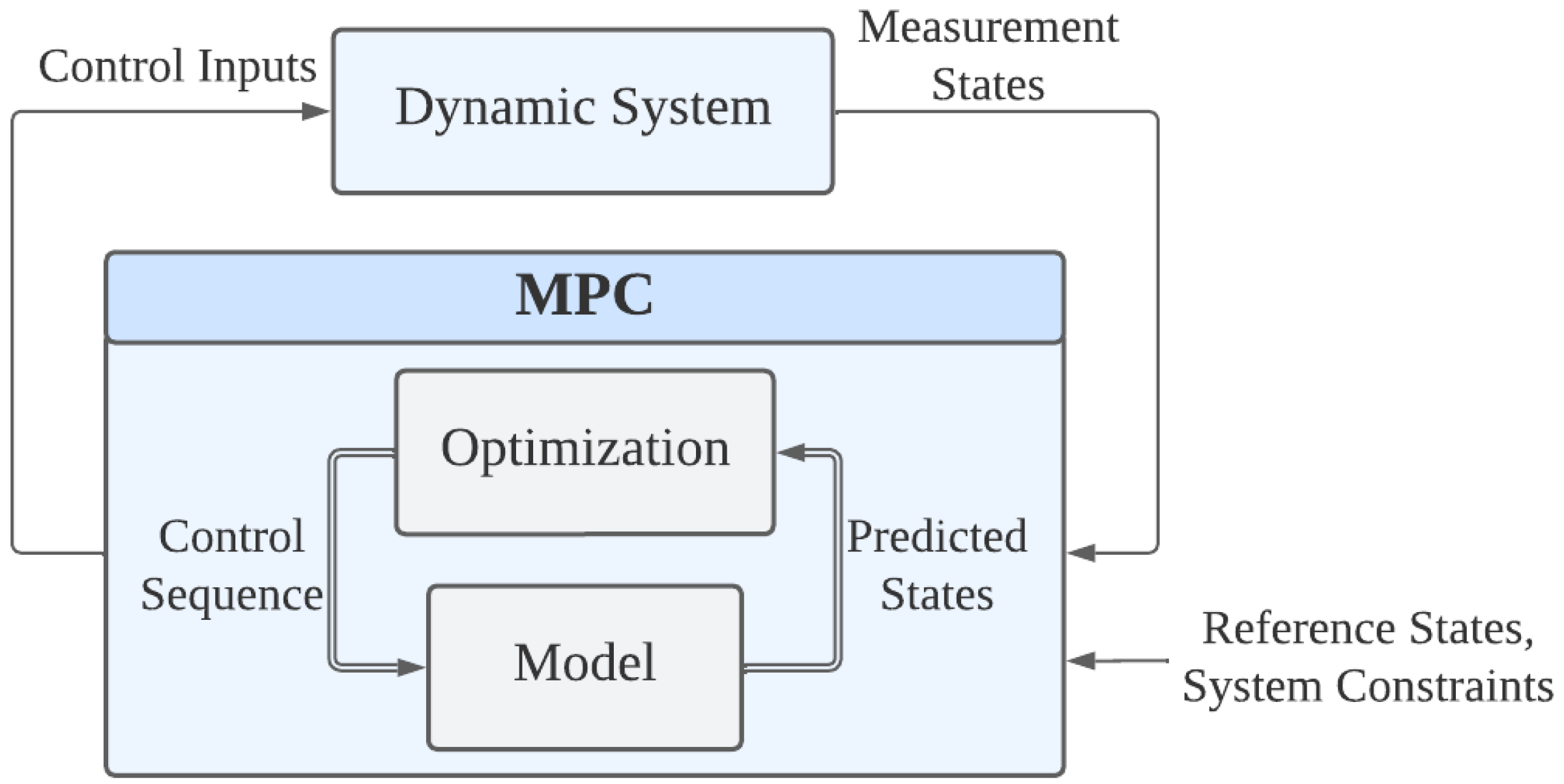
MPC is a model based control strategy, which determines the control action by recursively solving OCPs and respects the system constraints during the control, as shown in
Figure 3.
Figure 3.
Control loop of the MPC, which mainly includes an optimizer and a prediction model.
Figure 3.
Control loop of the MPC, which mainly includes an optimizer and a prediction model.
In the MPC control loop, it receives reference states, system constraints and measurement states from the dynamic system, and outputs the control inputs back to the system. The MPC calculates the predicted outputs based on the prediction model with a sequence of control inputs over a certain horizon, and the optimizer solves the quadratic programming (QP) problem as:
where
and
represent control inputs and system states at time
t;
T is the prediction horizon which refers to the number of time steps to look forward;
and
are the stage reference states in the prediction horizon and the terminal reference states respectively;
Q and
are the weighting matrics for stage states and terminal states;
and
are the prediction model and system output function; and
and
are constraints in control inputs and system states.
When designing a real-world system, it is important to consider the input constraints based on the physical limits of the actuator being used. In this case, the control inputs are bounded, as , , , . and represent the maximum allowed force and moment limits, respectively.
In this study, the MPC also takes system constraints into account. The vehicle’s linear velocity are limited as , and angular velocity are also limited as . Here, represents the maximum linear velocity and represents the maximum angular velocity.
In tuning MPC, several key steps are involved. These include defining control objectives, selecting prediction and control horizons, assigning weighting factors to prioritize objectives, setting constraint limits for inputs and states, evaluating and refining performance through simulations, considering robustness measures for uncertainties, and validating the tuned controller through real-world experiments. By following these steps, we can effectively tune the MPC controller to achieve the desired control performance.
The estimated states
provided by the EAOB are divided into two components. The first component consists of the estimated positions
and velocities
, which are utilized by the MPC module to enhance the accuracy of the system states. Simultaneously, the second component, the estimated disturbances
, is incorporated into the MPC’s prediction model as Equation
22 at each time step. According to
Assumption 2, the disturbance term
throughout the prediction horizon
T remains consistent with the estimated disturbance
at the current time step.
Therefore, the DOBMPC algorithm is implemented in a receding horizon as following steps:
At the sampling time instant, utilize prediction Equation 35 and update Equation 37 to estimate the disturbance using the EAOB approach.
Update the disturbance term in the prediction model of the MPC at the current time instant and within the prediction horizon using the estimated disturbance .
The OCP in the Equation 41 is solved to obtain the optimized control sequence .
The first set of the control sequence is implemented in the dynamic system, while the rest will be treated as initial condition in the next iteration.
At the next sampling instant, the OCP in the Equation 41 will be solved again with the measurement states and new initial condition.
To realize the MPC, the OCP should be discretized from
to
and solved with multiple shooting schemes. Therefore, it becomes a sequential quadratic programming (SQP) which is executed in a real-time iteration scheme [
32]. In this research work, the implementations are completed through ACADOS [
33].
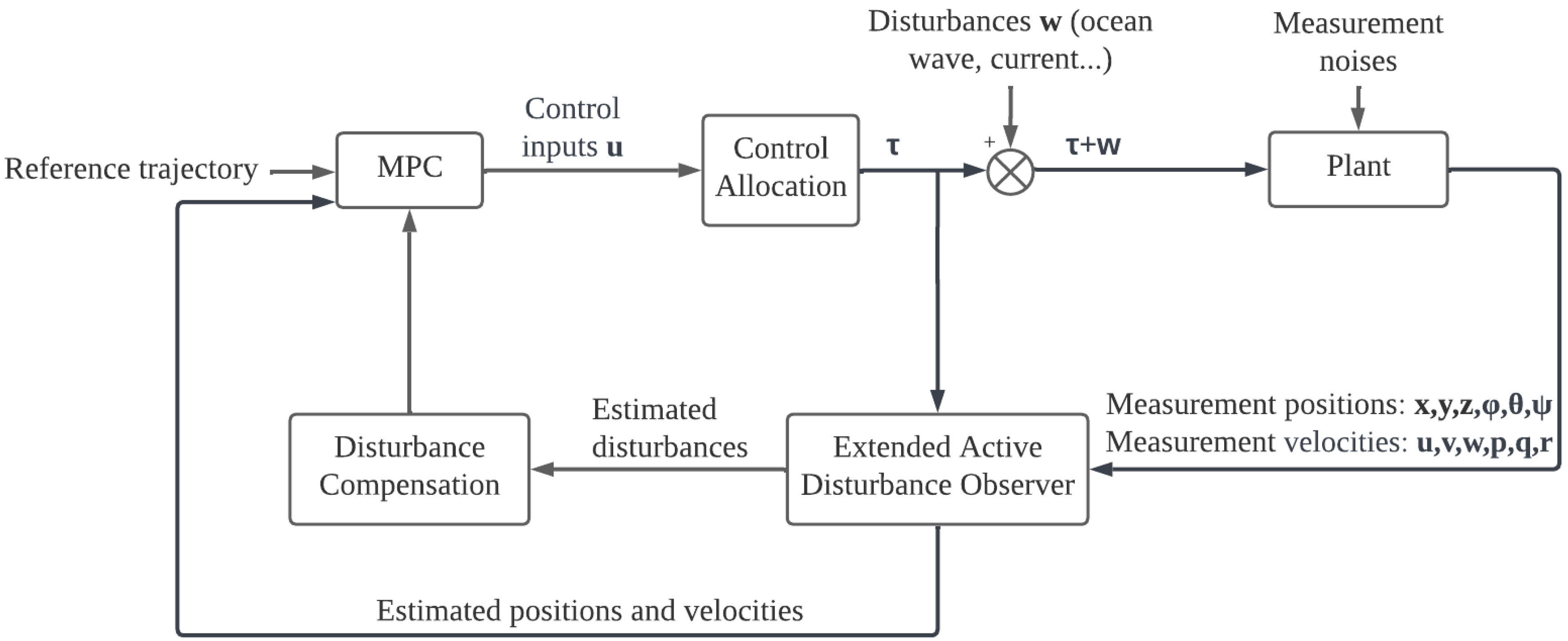
The overall block diagram of the proposed DOBMPC is shown in
Figure 4. The EAOB receives measurement positions and velocities, then outputs the estimated positions, velocities, and disturbances. MPC takes estimate positions and velocities as system states and outputs the control inputs based on the reference trajectory. The estimated disturbances are compensated directly into the MPC prediction model as parameter
. Therefore, the prediction model becomes a parameter-varying model, which makes the MPC adaptive. The control inputs then go through the control allocation to drive the system plant.
Figure 4.
Block diagram of the proposed DOBMPC scheme with disturbance compensation incorporated.
Figure 4.
Block diagram of the proposed DOBMPC scheme with disturbance compensation incorporated.
5. Results and Discussion
The performance of the proposed DOBMPC is verified by simulation in the UUV Simulator [
34], which is an extension of the open-source robotics simulator Gazebo to underwater scenarios. It is also utilized to construct a more realistic simulation environment.
For real-world implementation, it is crucial to acquire measurements of system states, encompassing linear and angular position, as well as linear and angular velocity. In the absence of GPS signals in the underwater environment, alternative sensors are employed. Underwater acoustic positioning systems, such as ultra-short baseline (USBL), are commonly preferred due to their enhanced mobility, providing reliable linear position information for the UUV. The Attitude and Heading Reference System (AHRS) can be utilized to determine the UUV’s angular position, including pitch, roll, and yaw, enabling the acquisition of necessary attitude information. Additionally, the AHRS incorporates gyroscopes as part of its sensor suite, allowing the estimation of angular velocity. For the UUV’s linear velocity, the Doppler velocity log (DVL) is typically used. However, an alternative and more economical method exists, which estimates velocity based on thrust and a static relationship between thrust and velocity at steady state. It is important to note that this alternative method may exhibit reduced accuracy, particularly in the presence of significant external disturbances.
The specifications of the BlueROV2 used in this research work are defined in a Unified Robot Description Format (URDF) file, which is used for representing the robot model. The robot model in the URDF file follows the dynamic model in
Section 2. Therefore, the parameters in the BlueROV2’s model are shown in the following tables.
Table 2 indicates the rigid body parameter includes mass
m, weight
W, buoyancy
B, and inertia
.
Table 3 specifies the hydrodynamic terms, which include added mass produced when the UUV travels through the fluid and the linear damping force caused by the skin friction.
Table 2.
BlueROV2 rigid-body parameters defined in URDF file.
Table 2.
BlueROV2 rigid-body parameters defined in URDF file.
| Parameter |
Value |
| m |
11.26
|
| W |
112.8 N
|
| B |
114.8 N
|
|
0.3
|
|
0.63
|
|
0.58
|
Table 3.
BlueROV2 hydrodynamic parameters defined in URDF file.
Table 3.
BlueROV2 hydrodynamic parameters defined in URDF file.
| Direction |
Parameter |
Value |
| Surge |
|
1.7182
|
| Sway |
|
0
|
| Heave |
|
5.468
|
| Roll |
|
0
|
| Pitch |
|
1.2481
|
| Yaw |
|
0.4006
|
| Surge |
|
-11.7391
|
| Sway |
|
-20
|
| Heave |
|
-31.8678
|
| Roll |
|
-25
|
| Pitch |
|
-44.9085
|
| Yaw |
|
-5
|
In the disturbance rejection tests, two motion control problems are employed, which are dynamic positioning and trajectory tracking. The results from the proposed DOBMPC are compared against PID and baseline MPC controllers. Based on Fossen’s theory [
27], the disturbance term is defined in the force level as Equation
22. Therefore, to directly observe the disturbance rejection performance, the disturbances are generated as body wrench, which includes forces and moments in 4 DOF. The ROS service
is used to generate the forces and moments that act at the CG of the UUV in the IRF. Thus, the rotation matrix, as the Equation
6, is required to transfer the disturbances
that are estimated in the BRF to the IRF for comparing results.
Table 4 lists the MPC parameters that apply to both the proposed DOBMPC and baseline MPC. Since the prediction horizon is 60 and the sample time is 0.05 seconds, the system considers 3 seconds forward. The average time for solving the OCP problems is 7
, which allows the system to run in real-time. The PID parameters that utilized in this work are also listed in
Table 5.
Table 4.
MPC parameters utilized in this work.
Table 4.
MPC parameters utilized in this work.
| Controller parameters |
Value |
| Prediction horizon |
60 |
| Sample time (s) |
0.05 |
| Q |
[300 300 150 10 10 150 10 10 10 10 10 10 15 15 0.5 0.5] |
|
[300 300 150 10 10 150 10 10 10 10 10 10] |
| OCP time (ms) |
7 |
Table 5.
PID parameters utilized in this work.
Table 5.
PID parameters utilized in this work.
| Control gain |
Surge |
Sway |
Heave |
Yaw |
|
5 |
5 |
5 |
7 |
|
0.05 |
0.05 |
0.05 |
0.1 |
|
1.2 |
1.2 |
1.2 |
0.6 |
5.1. Dynamic Positioning Results
For dynamic positioning, the UUV encounters two types of disturbances: simulated periodic wave effects and constant current effects. These disturbances manifest as forces and moments acting on the UUV. In the case of periodic disturbances, sinusoidal waves with random force amplitudes ranging from 10 - 16
N are applied in the
,
, and
directions, while sinusoidal waves with random moment amplitudes ranging from 1 - 2
is applied around
axis. The UUV is set to remain stationary at the position
in the IRF while keeping a yaw angle of 0 degrees, in the presence of disturbances.
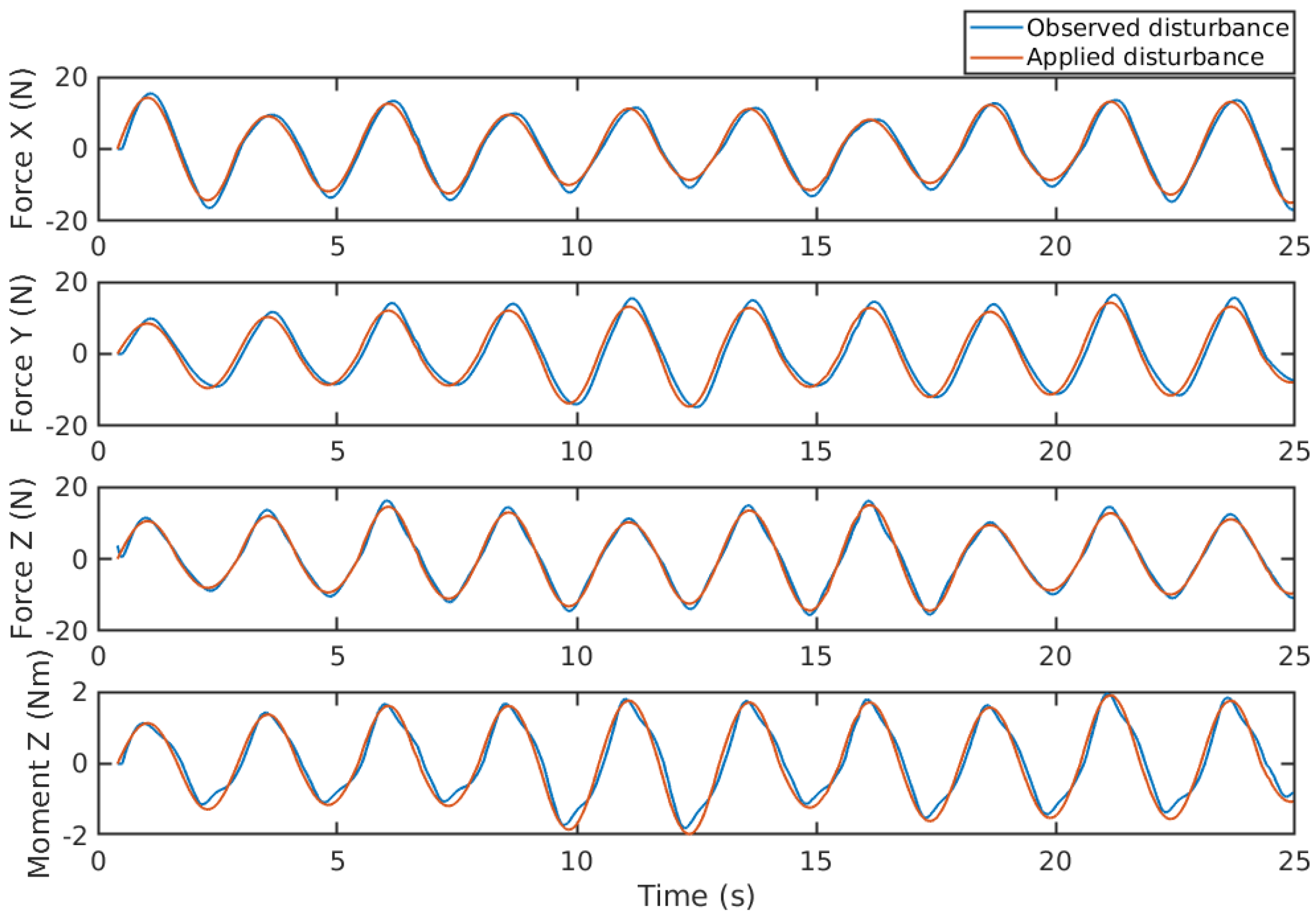
Figure 5 displays the estimated disturbances alongside the generated disturbances. As shown in the figure, the estimated disturbances closely match the generated disturbances, and the estimation delay is shorter than the sample time, proving the feasibility of the proposed EAOB.
Figure 5.
Disturbances estimation of periodic waves with random force and moment amplitudes.
Figure 5.
Disturbances estimation of periodic waves with random force and moment amplitudes.
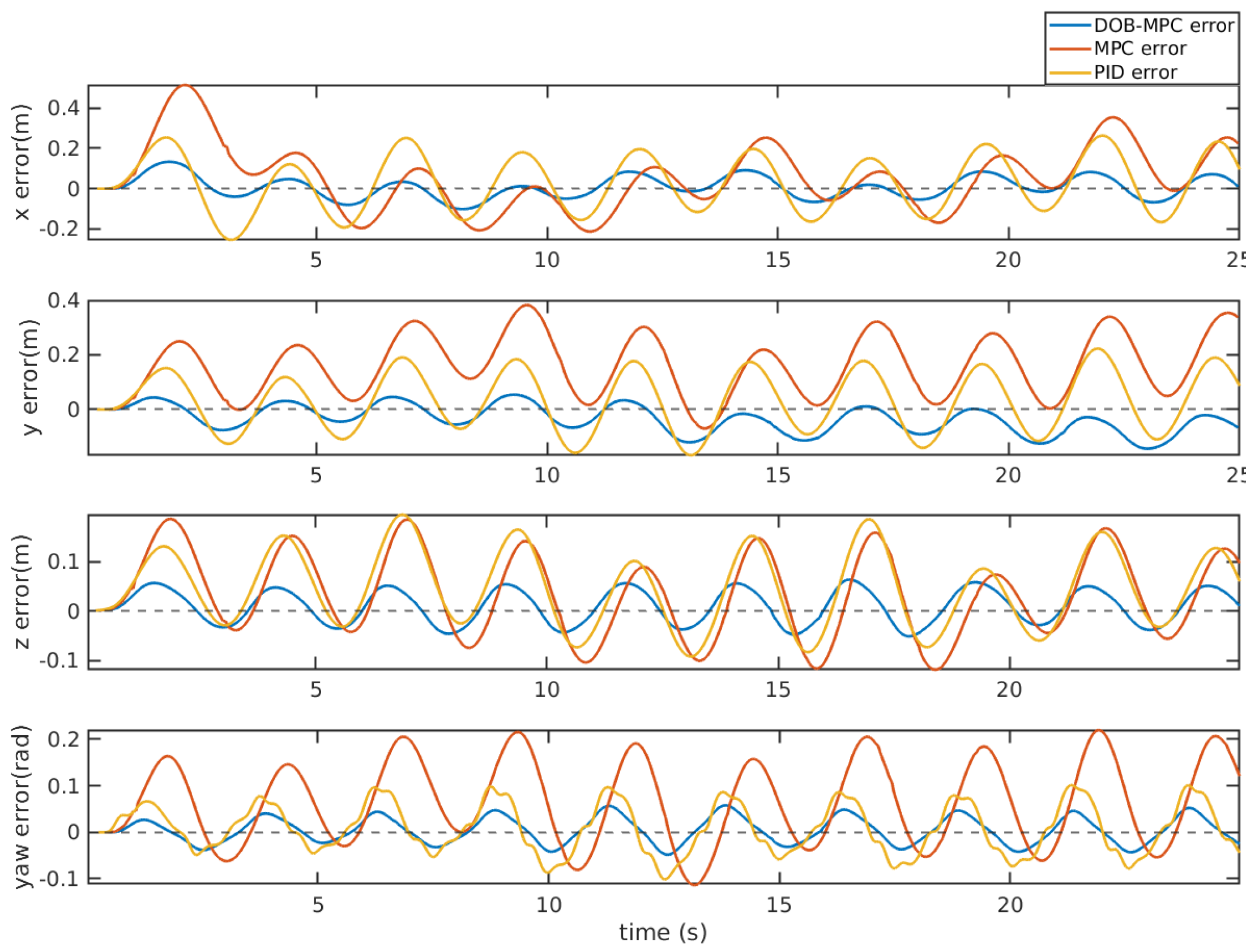
After compensating the estimated disturbances into the MPC’s prediction model, it improves the disturbance rejection ability of the controller significantly compared to the PID and the MPC, as shown in
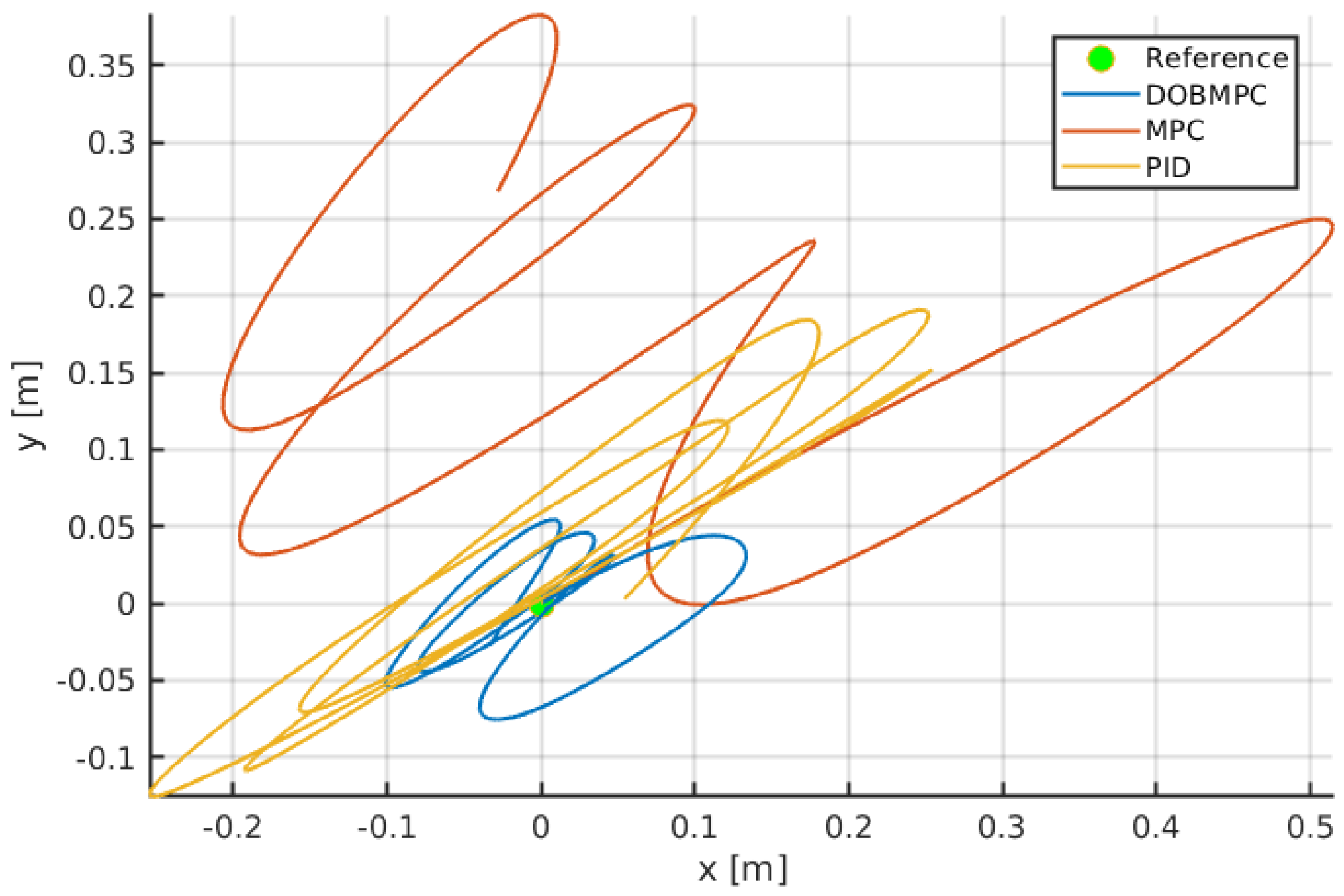
Figure 6. A 2D diagram which indicates the dynamic positioning results of three controllers are also demonstrated in
Figure 7, while the blue trajectory shows the DOBMPC can stay at the reference point more stably.
Figure 6.
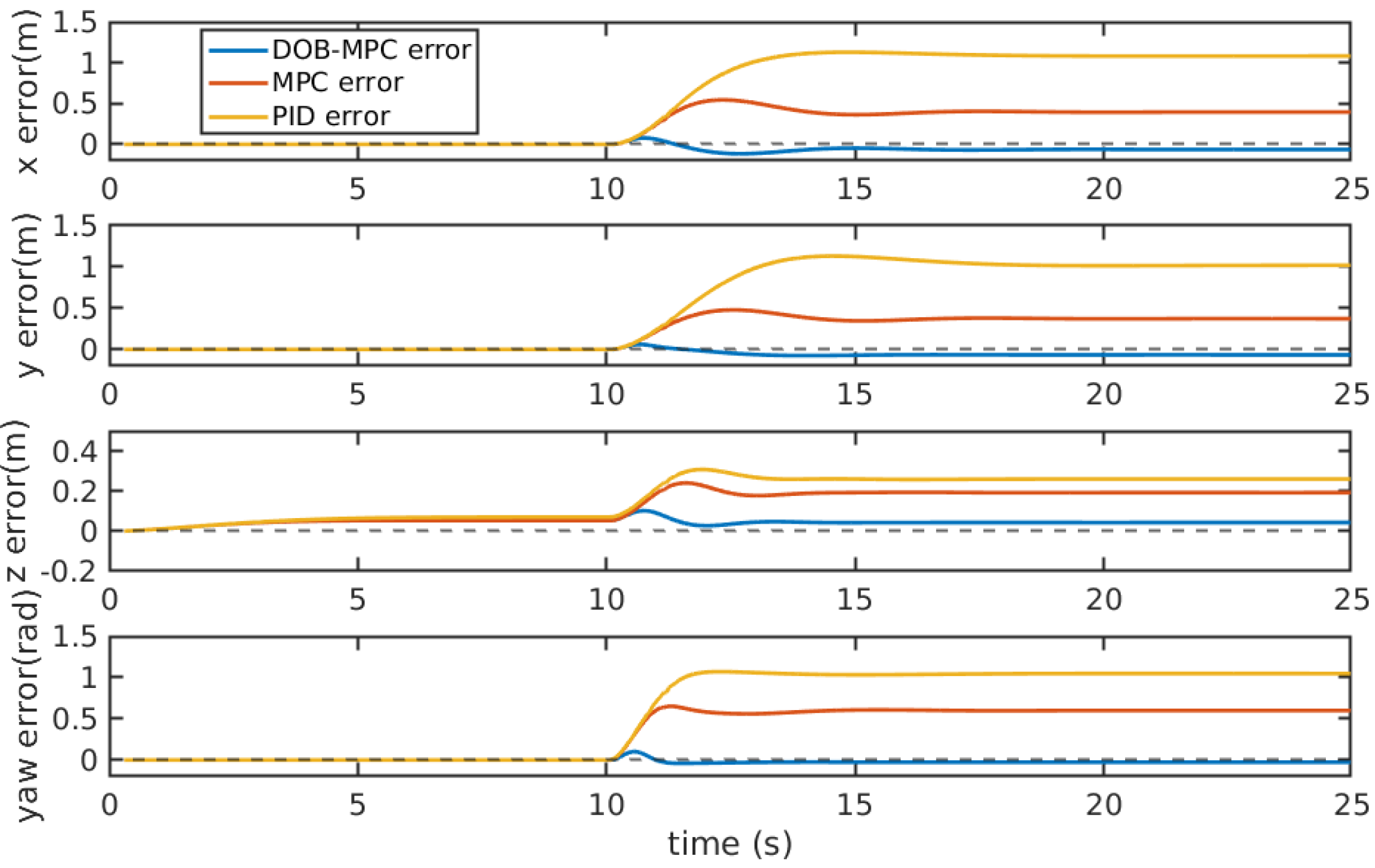
Tracking errors of the proposed DOBMPC, baseline MPC and PID controllers under periodic disturbances.
Figure 6.
Tracking errors of the proposed DOBMPC, baseline MPC and PID controllers under periodic disturbances.
Figure 7.
Trajectories of dynamic positioning results of the proposed DOBMPC, baseline MPC and PID controllers under periodic disturbances.
Figure 7.
Trajectories of dynamic positioning results of the proposed DOBMPC, baseline MPC and PID controllers under periodic disturbances.
To generate constant disturbances, a 10
N force is applied in the
,
, and
directions at time
, and a 5
torque is applied around
axis at the same time. In
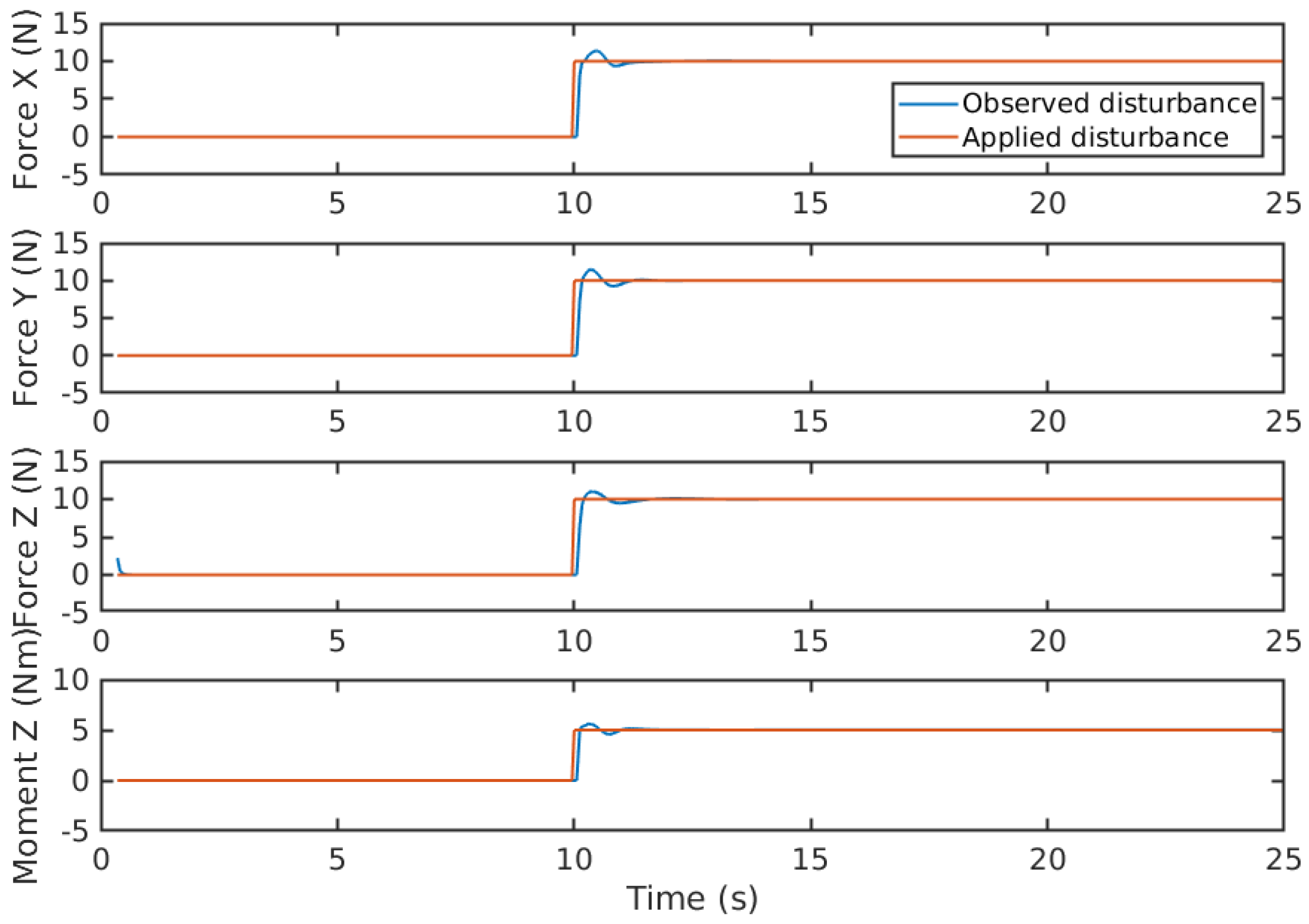
Figure 8, a slight overshoot can be observed when the disturbances abruptly change from 0
N to 10
N. This overshoot is caused by the significant difference in estimated states between two time steps. The EAOB takes less than 0.5 seconds to accurately adjust the estimated states using recursive iteration.
Figure 9 displays the tracking errors of the proposed DOBMPC, baseline MPC, and PID controllers when subjected to constant currents. It clearly demonstrates the varying levels of disturbance rejection capability among the three controllers. The DOBMPC controller precisely estimates disturbances and compensates for them, resulting in errors converging to zero in each direction. The x-y diagram in
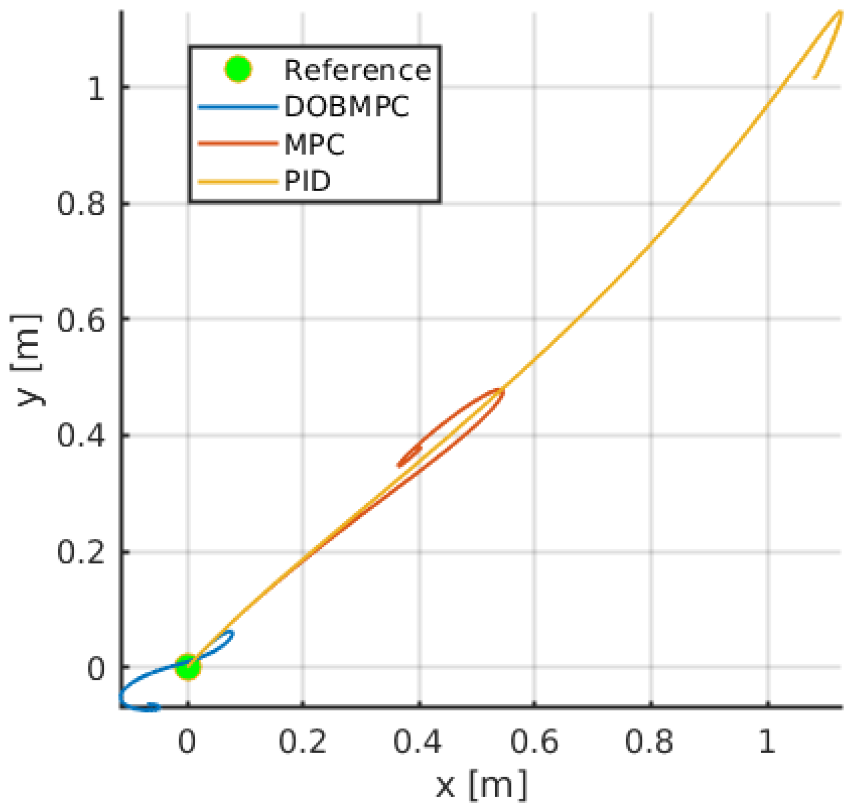
Figure 10 further illustrates the dynamic positioning performance of the three controllers. By overlaying disturbances in the same direction, it becomes evident that the proposed DOBMPC significantly enhances disturbance rejection ability.
Figure 8.
Disturbances estimation of constant currents in x, y, z directions.
Figure 8.
Disturbances estimation of constant currents in x, y, z directions.
Figure 9.
Tracking errors of the proposed DOBMPC, baseline MPC, and PID controllers under constant currents.
Figure 9.
Tracking errors of the proposed DOBMPC, baseline MPC, and PID controllers under constant currents.
Figure 10.
Trajectories of dynamic positioning results of the proposed DOBMPC, baseline MPC, and PID controllers under constant currents.
Figure 10.
Trajectories of dynamic positioning results of the proposed DOBMPC, baseline MPC, and PID controllers under constant currents.
5.2. Trajectory Tracking Results
To assess the performance of trajectory tracking, two kinds of movement scenarios are employed. Firstly, a circular path with a radius of 2
m is employed. The UUV’s yaw angle is defined to be relative to the surge direction. To assess the system’s robustness, a 10
N force is applied in the
,
, and
directions, along with a 5
torque around the
axis.
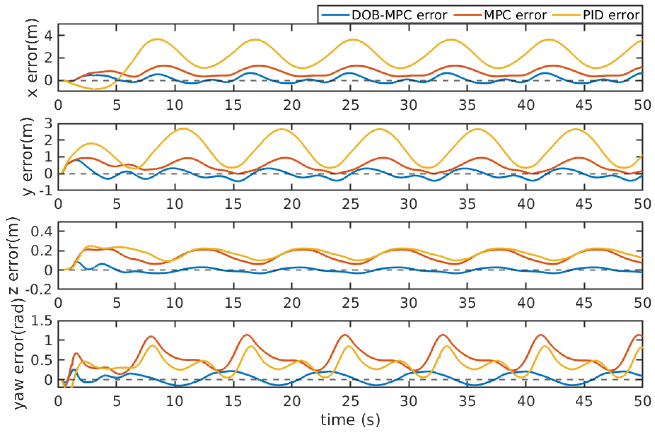
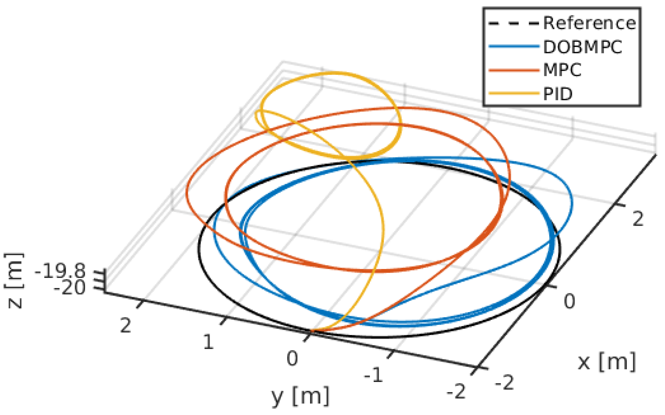
Figure 11 illustrates the comparison between the estimated disturbances and the generated disturbances. As the disturbance term incorporates unmodeled components from the dynamic model, the disparity between the estimated and generated disturbances can be attributed to the nonlinear damping force experienced by the UUV during circular trajectory movement. The tracking error of PID, MPC, and the proposed DOBMPC is shown in
Figure 13, demonstrating a significant reduction in tracking error with the proposed DOBMPC. Additionally,
Figure 12 and
Figure 14 provide a visual representation of the trajectory tracking results.
Figure 11.
Disturbances estimation of constant currents during circular trajectory tracking.
Figure 11.
Disturbances estimation of constant currents during circular trajectory tracking.
Figure 12.
Circular trajectory tracking results of the proposed DOBMPC, baseline MPC and PID controllers in x, y, z, and yaw directions.
Figure 12.
Circular trajectory tracking results of the proposed DOBMPC, baseline MPC and PID controllers in x, y, z, and yaw directions.
Figure 13.
Tracking errors of the proposed DOBMPC, baseline MPC and PID controllers under constant currents during circular trajectory tracking.
Figure 13.
Tracking errors of the proposed DOBMPC, baseline MPC and PID controllers under constant currents during circular trajectory tracking.
Figure 14.
Three-dimensional circular trajectory tracking results of the proposed DOBMPC, baseline MPC and PID controllers.
Figure 14.
Three-dimensional circular trajectory tracking results of the proposed DOBMPC, baseline MPC and PID controllers.
To evaluate the effectiveness of the proposed control method in tracking a highly nonlinear trajectory, a lemniscate trajectory with a 2
m amplitude is utilized. Throughout the movement, the yaw angle remains constant at 0 degrees. Additionally, periodic wave effects are incorporated into the testing process. These waves have random force amplitudes ranging from 10-16
N and random moment amplitudes ranging from 2-4
.
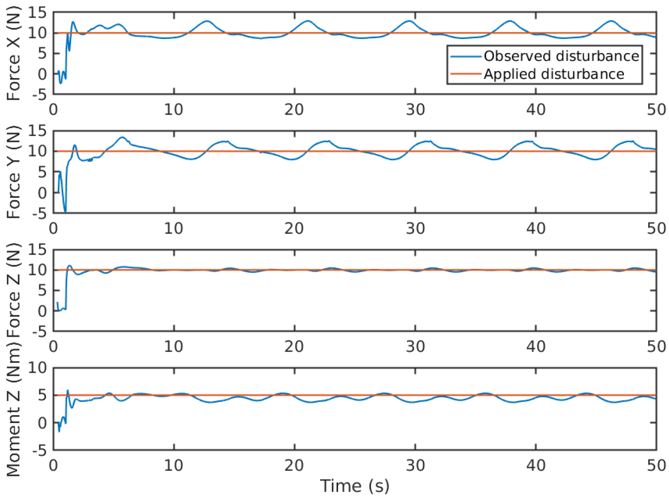
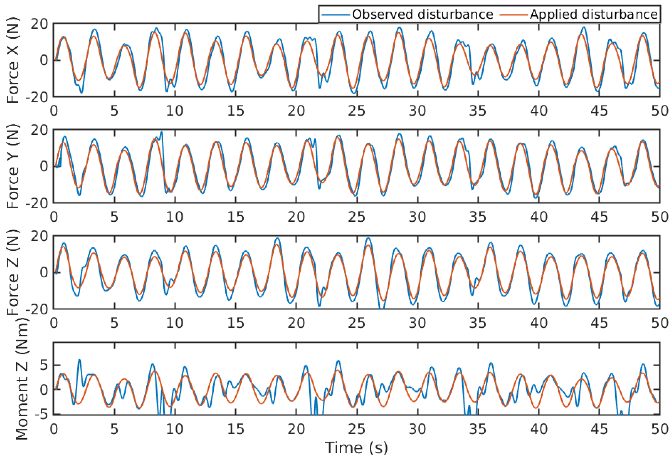
Figure 15 provides the comparison between generated disturbances and estimated disturbances. The results demonstrate that the disturbance forces in the
,
, and
directions can still be accurately estimated when following a lemniscate trajectory. However, challenges arise when accurately estimating the disturbance moment around
during the tracking of this trajectory. This can lead to occasional deviations or noise around the actual disturbance value. The complexity of unmodeled nonlinear hydrodynamics, which becomes more prominent when tracking a nonlinear trajectory like the lemniscate, could be a contributing factor to this issue. In
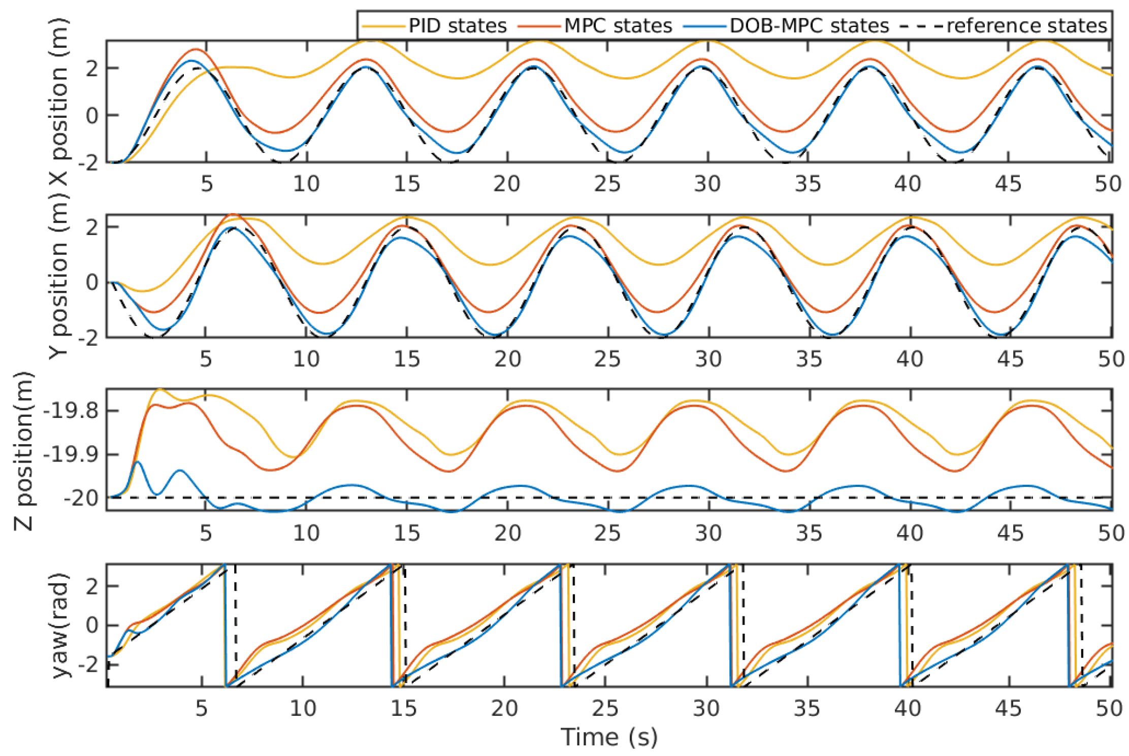
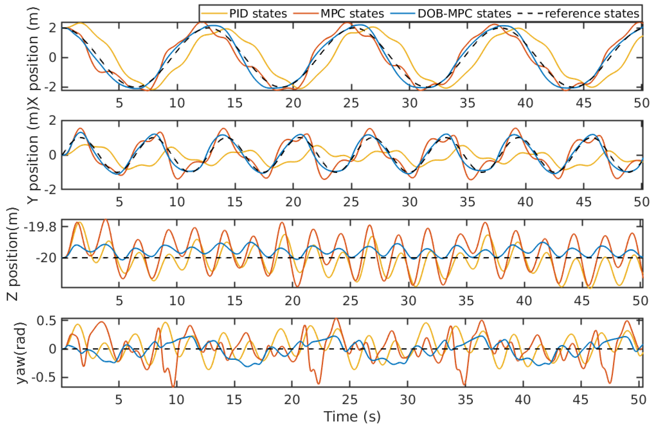
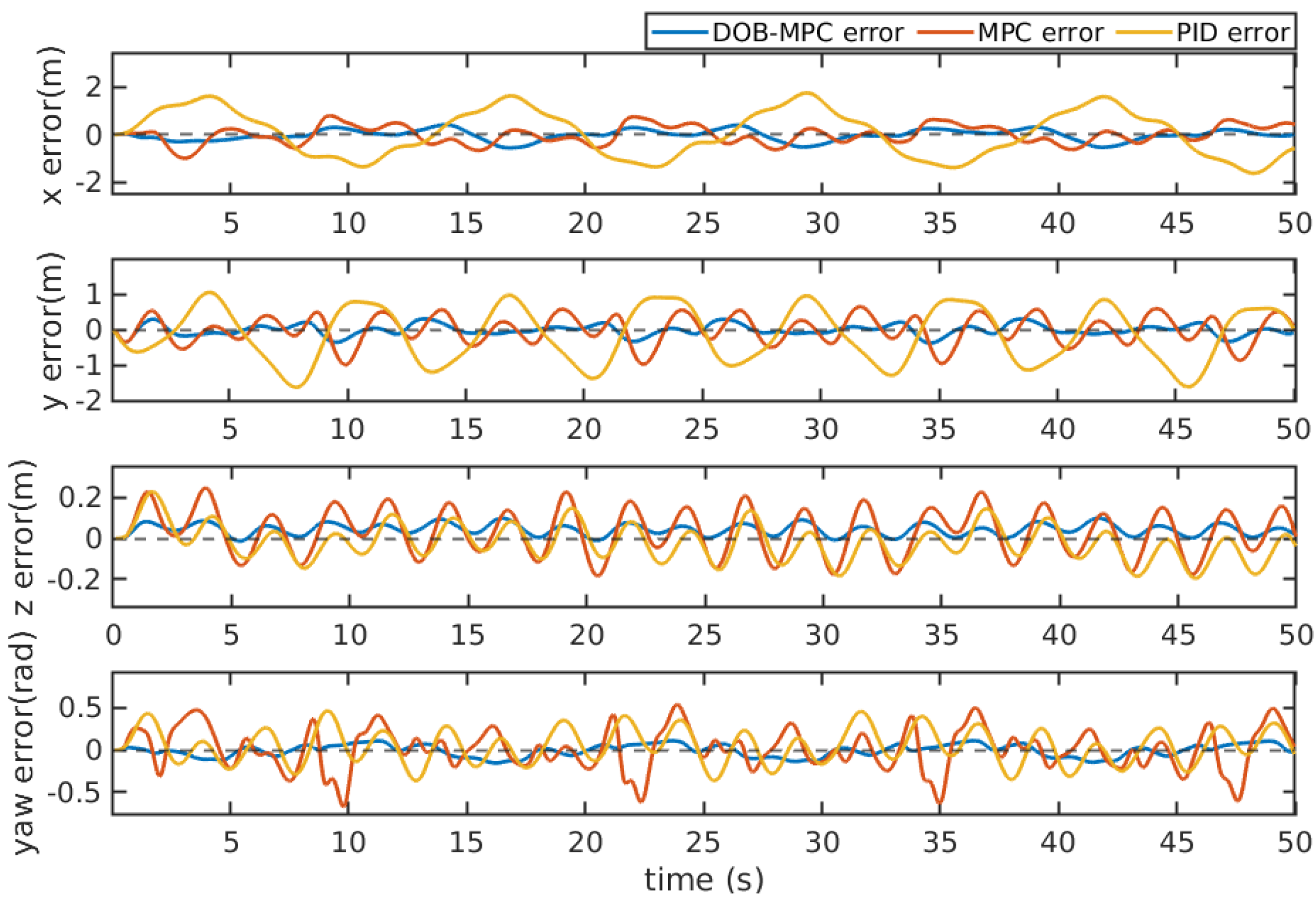
Figure 16, the system states of tracking a lemniscate trajectory under periodic waves are compared between PID, MPC, and the proposed DOBMPC. While the system states of PID and MPC exhibit irregularities due to time-varying massive disturbances, the states of DOBMPC remain relatively smooth. The tracking error, depicted in
Figure 17, shows a significant reduction with the proposed DOBMPC compared to PID and MPC. Lastly,
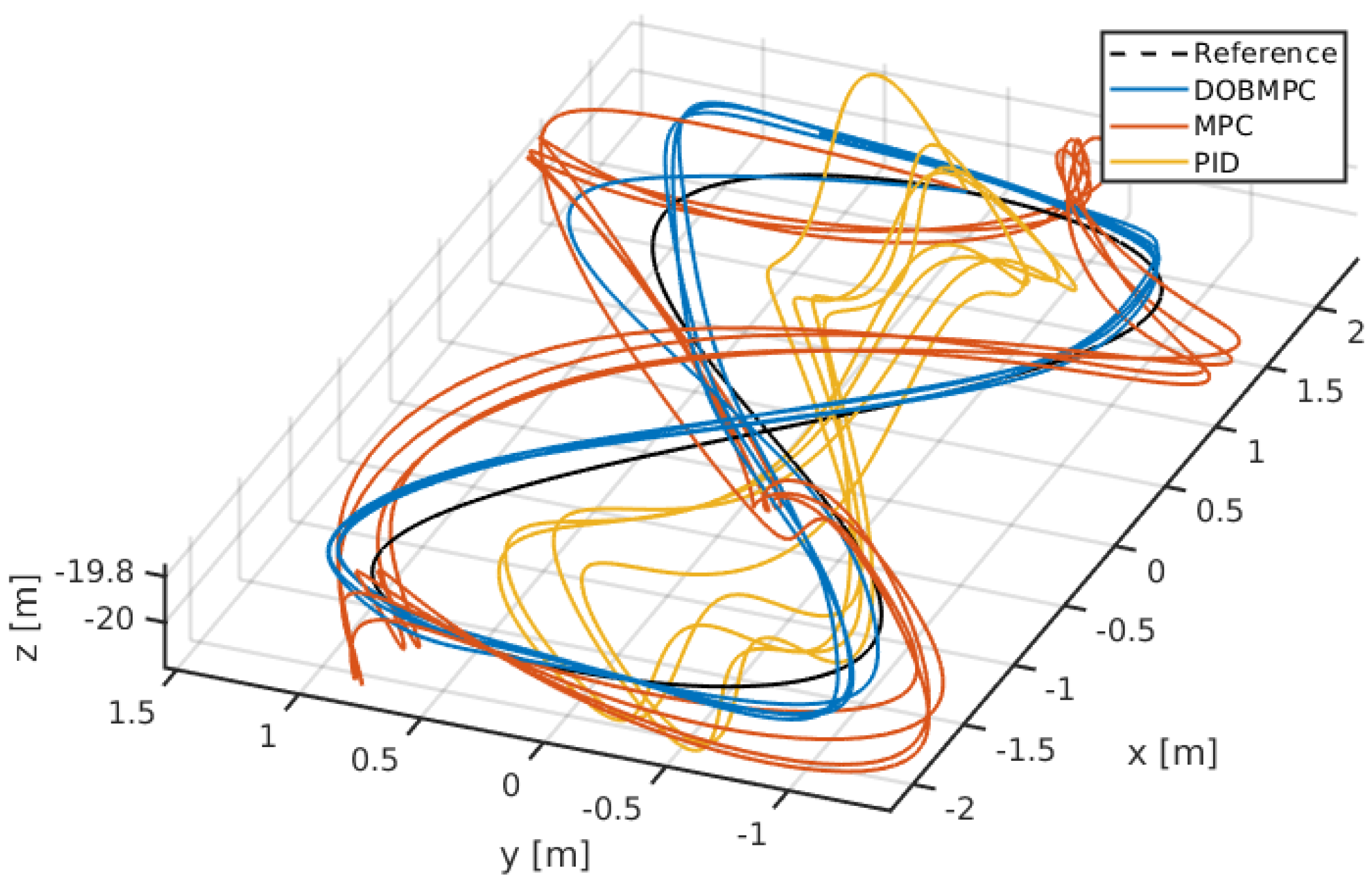
Figure 18 provides a visual representation of the trajectory tracking results in three dimensions.
Figure 15.
Disturbances estimation of periodic waves during lemniscate trajectory tracking.
Figure 15.
Disturbances estimation of periodic waves during lemniscate trajectory tracking.
Figure 16.
Lemniscate trajectory tracking results of the proposed DOBMPC, baseline MPC and PID controllers in x, y, z, and yaw directions.
Figure 16.
Lemniscate trajectory tracking results of the proposed DOBMPC, baseline MPC and PID controllers in x, y, z, and yaw directions.
Figure 17.
Tracking errors of the proposed DOBMPC, baseline MPC and PID controllers under constant currents during lemniscate trajectory tracking.
Figure 17.
Tracking errors of the proposed DOBMPC, baseline MPC and PID controllers under constant currents during lemniscate trajectory tracking.
Figure 18.
Three-dimensional lemniscate trajectory tracking results of the proposed DOBMPC, baseline MPC and PID controllers.
Figure 18.
Three-dimensional lemniscate trajectory tracking results of the proposed DOBMPC, baseline MPC and PID controllers.
5.3. Results Analysis
Table 6 presents an analysis of the performance of dynamic positioning and trajectory tracking of the UUV. The evaluation is based on the root mean square error (RMSE). RMSE is a commonly used metric in control systems literature and has been widely accepted as a measure of performance. The use of RMSE allows for easy comparison and interpretation of results across different controllers. It provides a quantitative measure that can be used to assess and rank the performance of different control strategies. Furthermore, RMSE is less sensitive to outliers compared to other metrics, such as Mean Absolute Error (MAE). It considers the squared errors, which amplifies the impact of larger errors, making it suitable for capturing the performance of control systems where extreme errors may occur.
The lowest RMSE in each row is highlighted. The results clearly demonstrate that the utilization of the proposed DOBMPC significantly enhances the system’s ability to reject disturbances.
Table 6.
RMSE of the proposed DOBMPC, baseline MPC, and PID controllers in dynamic positioning and trajectory tracking.
Table 6.
RMSE of the proposed DOBMPC, baseline MPC, and PID controllers in dynamic positioning and trajectory tracking.
| Motion |
Disturbance |
Direction |
PID (m) |
MPC (m) |
DOBMPC (m) |
| |
|
X |
0.1374 |
0.1689 |
0.0537 |
| Dynamic |
Periodic |
Y |
0.1095 |
0.1934 |
0.0605 |
| Positioning |
wave effects |
Z |
0.0871 |
0.0896 |
0.0350 |
| |
|
Yaw |
0.0536 |
0.1108 |
0.0282 |
| |
|
X |
0.7893 |
0.3099 |
0.0521 |
| Dynamic |
Constant |
Y |
0.7544 |
0.2882 |
0.0482 |
| Positioning |
current effects |
Z |
0.2032 |
0.1508 |
0.0469 |
| |
|
Yaw |
0.7858 |
0.4547 |
0.0491 |
| Circular |
|
X |
2.3626 |
0.8012 |
0.2924 |
| Trajectory |
Constant |
Y |
1.6433 |
0.5521 |
0.2629 |
| Tracking |
current effects |
Z |
0.1763 |
0.1510 |
0.0233 |
| |
|
Yaw |
0.4355 |
0.6325 |
0.2582 |
| Lemniscate |
|
X |
0.9854 |
0.3764 |
0.2306 |
| Trajectory |
Constant |
Y |
0.7732 |
0.3844 |
0.1504 |
| Tracking |
current effects |
Z |
0.0877 |
0.1133 |
0.0510 |
| |
|
Yaw |
0.2059 |
0.2413 |
0.1457 |
6. Conclusions
In this paper, a robust DOBMPC has been developed for dynamic positioning and trajectory tracking of an UUV in the presence of unpredictable disturbances. The simulation results provide evidence of the control strategy’s effectiveness in rejecting disturbances. The proposed control strategy offers several significant contributions. Firstly, it demonstrates the ability to estimate time-varying disturbances in real-time, enabling prompt compensation. Secondly, it exhibits robustness against measurement noise, ensuring reliable performance. Additionally, the control strategy effectively captures and compensates for unmodeled parameters in the system dynamics, enhancing its adaptability. Moreover, the MPC framework guarantees the consideration of system constraints during the recursive solving the optimal control problem. This ensures the UUV operates within defined limits. The estimated disturbances are directly incorporated into the MPC’s prediction model at each time step, enabling the calculation of an optimal control law. In summary, the developed DOBMPC approach provides a robust control strategy for dynamic positioning and trajectory tracking of UUVs, effectively compensating for disturbances, considering system constraints, and accommodating unmodeled parameters.
The future work encompasses two primary aspects. Firstly, a comparative analysis can be conducted to assess the effectiveness and robustness of the proposed DOBMPC in relation to other robust controllers, such as SMC [
35], which have the capability to adapt to complex operational environments. This comparison will provide valuable insights into the performance of the proposed approach. Secondly, the validation of the DOBMPC can be enhanced by conducting simulations in a more realistic environment. It can be achieved by using computational fluid dynamics to create a wave model [
36]. This will allow for a better representation of real-world conditions and further evaluation and refinement of the DOBMPC’s performance.
Author Contributions
Conceptualization, Y.H., B.L. and B.J.; methodology, Y.H. and B.L.; software, Y.H. and B.J.; validation, Y.H.; formal analysis, Y.H., B.L. and B.J.; investigation, Y.H. and B.J. and J.H.; resources, Y.H., B.L. and J.H.; data curation, Y.H.; writing—original draft preparation, Y.H.; writing—review and editing, B.L., C.-Y.W. and Y.H.; visualization, Y.H.; supervision, C.-Y.W. and B.L.; project administration, C.-Y.W. and B.L.; funding acquisition, C.-Y.W. All authors have read and agreed to the published version of the manuscript.
Funding
This research was funded by the Research Centre for Unmanned Autonomous Systems and the Department of Civil and Environmental Engineering at The Hong Kong Polytechnic University.
Institutional Review Board Statement
Not applicable.
Informed Consent Statement
Not applicable.
Data Availability Statement
Not applicable.
Conflicts of Interest
The authors declare no conflict of interest.
References
- Hou, Shitong and Jiao, Dai and Dong, Bin and Wang, Haochen and Wu, Gang. Underwater inspection of bridge substructures using sonar and deep convolutional network. Advanced Engineering Informatics 2022, 52, 101545. [Google Scholar] [CrossRef]
- Hu, Sijie and Feng, Rendong and Wang, Zhanglin and Zhu, Chengcheng and Wang, Zhikun and Chen, Ying and Huang, Haocai. Control system of the autonomous underwater helicopter for pipeline inspection. Ocean Engineering 2022, 266, 113190. [Google Scholar] [CrossRef]
- Barker, Laughlin DL and Jakuba, Michael V and Bowen, Andrew D and German, Christopher R and Maksym, Ted and Mayer, Larry and Boetius, Antje and Dutrieux, Pierre and Whitcomb, Louis L. Scientific challenges and present capabilities in underwater robotic vehicle design and navigation for oceanographic exploration under-ice. Remote Sensing 2020, 12, 2588. [Google Scholar] [CrossRef]
- Mogstad, Aksel Alstad and degård, yvind and Nornes, Stein Melvær and Ludvigsen, Martin and Johnsen, Geir and Sørensen, Asgeir J and Berge, Jørgen. Mapping the historical shipwreck figaro in the high arctic using underwater sensor-carrying robots. Remote Sensing 2020, 12, 997. [Google Scholar] [CrossRef]
- Summers, Natalie and Johnsen, Geir and Mogstad, Aksel and Løvås, Håvard and Fragoso, Glaucia and Berge, Jørgen. Underwater hyperspectral imaging of Arctic macroalgal habitats during the polar night using a novel mini-ROV-UHI portable system. Remote sensing 2022, 14, 1325. [Google Scholar] [CrossRef]
- Preuß, Henrich and Cherewko, Valeska and Wollstadt, Johann and Wendt, Anne and Renkewitz, Helge. Crawfish Goes Swimming: Hardware Architecture of a Crawling Skid for Underwater Maintenance with a BlueROV2. OCEANS 2022, Hampton Roads, 2022, pp. 1–5. [CrossRef]
- Mai, Christian and Benzon, Malte von and Sørensen, Fredrik F. and Klemmensen, Sigurd S. and Pedersen, Simon and Liniger, Jesper. Design of an Autonomous ROV for Marine Growth Inspection and Cleaning. 2022 IEEE/OES Autonomous Underwater Vehicles Symposium (AUV), 2022, pp. 1–6. [CrossRef]
- Mao, Juzheng and Song, Guangming and Hao, Shuang and Zhang, Mingquan and Song, Aiguo. Development of a Lightweight Underwater Manipulator for Delicate Structural Repair Operations. IEEE Robotics and Automation Letters 2023, 8, 6563–6570. [Google Scholar] [CrossRef]
- Woolsey, C. Review of Marine Control Systems: Guidance, Navigation, and Control of Ships, Rigs and Underwater Vehicles. Journal of Guidance, Control, and Dynamics 2005, 28, 574–575. [Google Scholar] [CrossRef]
- Liu, Lu and Zhang, Lichuan and Pan, Guang and Zhang, Shuo. Robust yaw control of autonomous underwater vehicle based on fractional-order PID controller. Ocean Engineering 2022, 257, 111493. [Google Scholar] [CrossRef]
- Hasan, Mustafa Wassef and Abbas, Nizar Hadi. Disturbance Rejection for Underwater robotic vehicle based on adaptive fuzzy with nonlinear PID controller. ISA Transactions 2022, 130, 360–376. [Google Scholar] [CrossRef] [PubMed]
- Bingul, Zafer and Gul, Kursad. Intelligent-PID with PD Feedforward Trajectory Tracking Control of an Autonomous Underwater Vehicle. Machines 2023, 11, 300. [Google Scholar] [CrossRef]
- Healey, A.; Lienard, D. Multivariable sliding mode control for autonomous diving and steering of unmanned underwater vehicles. IEEE Journal of Oceanic Engineering 1993, 18, 327–339. [Google Scholar] [CrossRef]
- Yan, Zheping and Wang, Man and Xu, Jian. Robust adaptive sliding mode control of underactuated autonomous underwater vehicles with uncertain dynamics. Ocean Engineering 2019, 173, 802–809. [Google Scholar] [CrossRef]
- Lv, Tu and Zhou, Junliang and Wang, Yujia and Gong, Wei and Zhang, Mingjun. Sliding mode based fault tolerant control for autonomous underwater vehicle. Ocean Engineering 2020, 216, 107855. [Google Scholar] [CrossRef]
- Carreras, M.; Batlle, J.; Ridao, P. Hybrid coordination of reinforcement learning-based behaviors for AUV control. Proceedings 2001 IEEE/RSJ International Conference on Intelligent Robots and Systems. Expanding the Societal Role of Robotics in the the Next Millennium (Cat. No.01CH37180), 2001, Vol. 3, pp. 1410–1415 vol.3. [CrossRef]
- Elhaki, Omid and Shojaei, Khoshnam. A robust neural network approximation-based prescribed performance output-feedback controller for autonomous underwater vehicles with actuators saturation. Engineering Applications of Artificial Intelligence 2020, 88, 103382. [Google Scholar] [CrossRef]
- Patre, B.M.; Londhe, P.S.; Waghmare, L.M.; Mohan, S. Disturbance estimator based non-singular fast fuzzy terminal sliding mode control of an autonomous underwater vehicle. Ocean Engineering 2018, 159, 372–387. [Google Scholar] [CrossRef]
- Lakhekar, Girish Vithalrao and Waghmare, Laxman M. and Roy, Rupam Gupta. Disturbance Observer-Based Fuzzy Adapted S-Surface Controller for Spatial Trajectory Tracking of Autonomous Underwater Vehicle. IEEE Transactions on Intelligent Vehicles 2019, 4, 622–636. [CrossRef]
- Kamel, M.; Stastny, T.; Alexis, K.; Siegwart, R. Model predictive control for trajectory tracking of unmanned aerial vehicles using robot operating system. Robot Operating System (ROS) The Complete Reference (Volume 2). [CrossRef]
- Veksler, A.; Johansen, T.A.; Borrelli, F.; Realfsen, B. Dynamic Positioning With Model Predictive Control. IEEE Transactions on Control Systems Technology 2016, 24, 1340–1353. [Google Scholar] [CrossRef]
- Medagoda, L.; Williams, S.B. Model predictive control of an autonomous underwater vehicle in an in situ estimated water current profile. 2012 Oceans - Yeosu, 2012, pp. 1–8. [CrossRef]
- Shen, C.; Shi, Y.; Buckham, B. Trajectory Tracking Control of an Autonomous Underwater Vehicle Using Lyapunov-Based Model Predictive Control. IEEE Transactions on Industrial Electronics 2018, 65, 5796–5805. [Google Scholar] [CrossRef]
- Cao, Y.; Li, B.; Li, Q.; Stokes, A.A.; Ingram, D.M.; Kiprakis, A. A Nonlinear Model Predictive Controller for Remotely Operated Underwater Vehicles With Disturbance Rejection. IEEE Access 2020, 8, 158622–158634. [Google Scholar] [CrossRef]
- Arcos-Legarda, J.; Gutiérrez, Á. Robust Model Predictive Control Based on Active Disturbance Rejection Control for a Robotic Autonomous Underwater Vehicle. Journal of Marine Science and Engineering 2023, 11, 929. [Google Scholar] [CrossRef]
- Robotics, B. BlueROV2: The World’s Most Affordable High-Performance ROV. BlueROV2 Datasheet; Blue Robotics: Torrance, CA, USA 2016. [Google Scholar]
- Fossen, T.I. Handbook of marine craft hydrodynamics and motion control; John Wiley & Sons, 2011; pp. 167–183. [Google Scholar]
- Chondros, T.G. Distinguished figures in mechanism and machine science: Their contributions and legacies Part 1; Springer, 2007; pp. 1–30. [Google Scholar]
- Frogerais, Paul and Bellanger, Jean-Jacques and Senhadji, Lotfi. Various ways to compute the continuous-discrete extended Kalman filter. IEEE Transactions on Automatic Control 2011, 57, 1000–1004. [Google Scholar] [CrossRef]
- Chan, Linping and Naghdy, Fazel and Stirling, David. Extended active observer for force estimation and disturbance rejection of robotic manipulators. Robotics and Autonomous Systems 2013, 61, 1277–1287. [Google Scholar] [CrossRef]
- Kalman, Rudolph E and Bucy, Richard S. New results in linear filtering and prediction theory. Journal of Fluids Engineering 1961, 84. [Google Scholar] [CrossRef]
- Diehl, M.; Bock, H.G.; Diedam, H.; Wieber, P.B. Fast direct multiple shooting algorithms for optimal robot control. Fast motions in biomechanics and robotics: optimization and feedback control. [CrossRef]
- Verschueren, R.; Frison, G.; Kouzoupis, D.; van Duijkeren, N.; Zanelli, A.; Quirynen, R.; Diehl, M. Towards a modular software package for embedded optimization. IFAC-PapersOnLine 2018, 51, 374–380. [Google Scholar] [CrossRef]
- Manhães, M.M.M.; Scherer, S.A.; Voss, M.; Douat, L.R.; Rauschenbach, T. UUV Simulator: A Gazebo-based package for underwater intervention and multi-robot simulation. OCEANS 2016 MTS/IEEE Monterey. IEEE, 2016. [CrossRef]
- von Benzon, Malte and Sørensen, Fredrik Fogh and Uth, Esben and Jouffroy, Jerome and Liniger, Jesper and Pedersen, Simon. An Open-Source Benchmark Simulator: Control of a BlueROV2 Underwater Robot. Journal of Marine Science and Engineering 2022, 10, 1898. [Google Scholar] [CrossRef]
- Li, Zhaobin and Deng, Ganbo and Queutey, Patrick and Bouscasse, Benjamin and Ducrozet, Guillaume and Gentaz, Lionel and Le Touzé, David and Ferrant, Pierre. Comparison of wave modeling methods in CFD solvers for ocean engineering applications. Ocean Engineering 2019, 188, 106237. [Google Scholar] [CrossRef]
|
Disclaimer/Publisher’s Note: The statements, opinions and data contained in all publications are solely those of the individual author(s) and contributor(s) and not of MDPI and/or the editor(s). MDPI and/or the editor(s) disclaim responsibility for any injury to people or property resulting from any ideas, methods, instructions or products referred to in the content. |
© 2023 by the authors. Licensee MDPI, Basel, Switzerland. This article is an open access article distributed under the terms and conditions of the Creative Commons Attribution (CC BY) license (http://creativecommons.org/licenses/by/4.0/).
