1. Introduction
Pipeline systems is commonly composed of pumps, valves, piping, clamps, fittings, etc. They are mainly used for fluid energy transfer and are widely used in aerospace, petrochemical, nuclear power and other fields.The fluid pulsation excitation of the hydraulic pump and the base excitation of equipment can result in serious pipeline vibration which can cause the pipeline system damaged.[
1] This seriously affects the safety of the pipeline system, so there is an urgent need for good vibration damping methods for pipeline systems.
The traditional vibration reduction methods for pipeline systems mainly include clamp support vibration reduction, placing viscoelastic damping materials on the pipe’s exterior, and installing tuned mass dampers on the pipe body. Poor low-frequency vibration reduction effect, limited installation position, easy deformation, aging, and failure of damping materials are their shortcomings. However, they have good suppression effects on the high-frequency vibration of the pipeline.[
14,
15,
16,
17,
18,
19,
20,
21] N. Meyer et al.[
6] combined a discrete element model with a simplified finite element model and compared the validity of the method with experimental comparisons. The effect of particle damper position, filling rate, etc. on different modal parameters of the structure is analyzed. Zhao et al.[
7] designed a particle damper based on aircraft pipeline vibration damping, discussed the damper damping mechanism and the factors affecting damping. Effectiveness and practicality of particle dampers for aircraft lines verified by tests and finite element simulations. Zhang et al. [
8] provided a detailed review and discussion of the research content and progress of linear and nonlinear pipelines in the field of mechanics. Liu et al. [
9] proposed a frequency-domain transfer matrix method for fluid–solid coupling considering an elastically constrained liquid-filled pipeline based on pipeline vibration and verified the effectiveness of the method by means of measurement and simulation data. Based on Chen’s research, Zhou et al. [
10]designed a frequency-adjustable dynamic vibration absorber which could reduce the vibration of the pipeline at different resonance frequencies effectively. Panossion [
11] greatly reduced the high-frequency vibration (4000 Hz) of the liquid oxygen inlet blade by using particle damping technique. Xu et al.[
12,
13]
Particle collision damping and vibration damping techniques have been studied for a long time. The technology refers to the attachment of one or more dampers filled with a certain number of particles or the machining of a certain number of holes in the vibrating structure. The mechanism of vibration damping is through the collision and friction between particles and particles, particles and container wall to achieve the vibration damping of the structure.[
22,
23,
24,
25,
26]The technology has the advantages of wide temperature domain, wide frequency domain, radiation resistance, high reliability.[
3,
4,
5]
Currently, domestic and foreign scholars have obtained some research results regarding the mechanism of particle collision vibration reduction damping. However, less literature has been reported around the vibration damping aspects of piping systems. Therefore, this paper introduces particle collision-damping technology into the pipeline system. The effects of damper material and structure, external excitation and other parameters on the energy dissipation characteristics of particle collision damping are revealed via simulation analysis, numerical calculations and experiments. Particle collision damping is validated for vibration suppression on piping systems. Moreover, the experimental validation of particle collision damping shock absorber vibration suppression in the pipeline system is accomplished.
2. Theory of particle-vessel contact
Particle damping technology seeks to fill the damper cavity with a certain number of particles, using the collision and friction energy between the particles to attenuate the vibration of the pipeline system caused by external excitation. Among them, the particle collision mode is mainly divided into normal and tangential collision [
2].
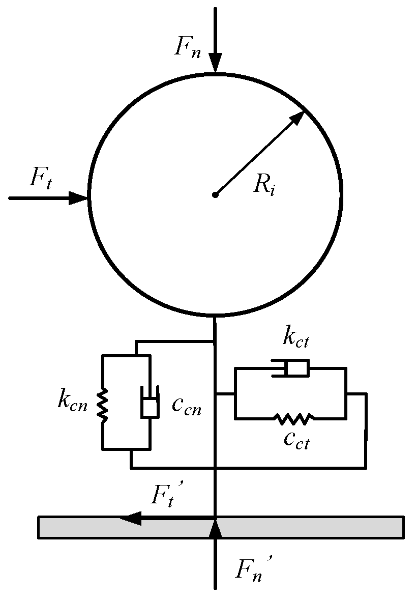
Figure 1 represents the normal and tangential contact between a single particle and the container wall.
are the normal and tangential forces between the particles and the vessel wall, respectively.
kcn,
kct are the normal and tangential equivalent stiffnesses between the particles and the container wall, respectively.
ccn,
cct are the normal and tangential damping coefficients between the particles and the container wall, respectively.
2.1. Normal contact between particle and vessel
The particles move in the normal direction towards the vessel wall with a certain velocity. A normal force is generated when the particle comes into contact with the surface of the vessel wall.
where
is the normal relative displacement between the particle and the vessel wall.
is the velocity between the particle and the vessel wall.
The expression for the normal stiffness coefficient between the particle and the vessel wall is:
Where Ec and μc are the modulus of elasticity and Poisson's ratio of the vessel, respectively.
The expression for the normal damping coefficient between the particles and the vessel wall is:
2.2. Tangential contact between particle and vessel
Tangential forces are generated when particles come into contact with the container surface in the tangential direction.
μs is the coefficient of friction between the particle and the container. is the tangential velocity of the particle with respect to the container.
The expression for the tangential stiffness coefficient between the particle and the container is:
α is the scaling factor.
The expression for the tangential damping coefficient between the particles and the vessel is:
3. Design and simulation analysis of particle collision damper for pipelines
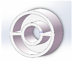
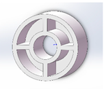
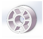
3.1. Pipeline particle collision damper design
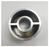
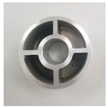
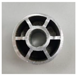
According to the structural characteristics of the pipeline shape, two types of materials and three types of unit structures of the pipeline particle collision damper were designed, and their structural diagrams and shape parameters are shown in
Table 1 and
Table 2, respectively.
3.2. Parameterisation
In this paper, The discrete unit software EDEM was used to simulate the state of motion and energy consumption of the particle system.The contact type was set to Hertz-Mindlin (no slip), and the materials and contact parameters used in the simulation are shown in
Table 3 and
Table 4. According to the actual working conditions, the simulation selects the time step as 25% of the Rayleigh time step, and the grid size is 2.5 times of the minimum radius of the filled particles.
3.3. Analysis of the influence of material and structural parameters of particle collision damper for pipelines
3.3.1. Effect of particle fill rate on system energy consumption
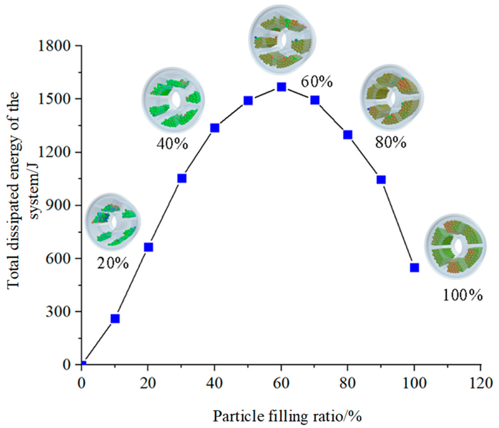
The particle collision damper is filled with 2 mm steel ball particles.Other conditions remain the same.The number of particles and the corresponding mass ratios at different filling rates are shown in
Table 5.
From
Figure 2, it can be seen that the total collision energy dissipation value of the particle system shows a trend of increasing and then decreasing with the increase of particle filling rate. The total dissipated energy of the granular system is highest when the fill rate is 60% cent. There is an optimal particle fill rate for particle collision dampers in such conditions. When the particle fill rate is low, the number of particles in the container is low. Particle-to-particle and particle-to-vessel wall contact is limited, and less energy is dissipated through collision and friction. As the particle filling rate increases, the momentum exchange between particles and particles and between particles and vessel walls becomes more and more adequate. The total energy consumption of the pellet system is increasing. When the filling rate of the particles is higher than the optimal filling rate, the space for movement of the particles inside the vessel is limited. The energy dissipated through collision and friction decreases gradually. At 100% cent fill rate, the particles have very little movement, but energy can still be dissipated by friction between the particles. Therefore, the total energy dissipated at this fill rate is slightly better than that at 10% cent fill rate.
3.3.2. Effect of particle size on system energy consumption.
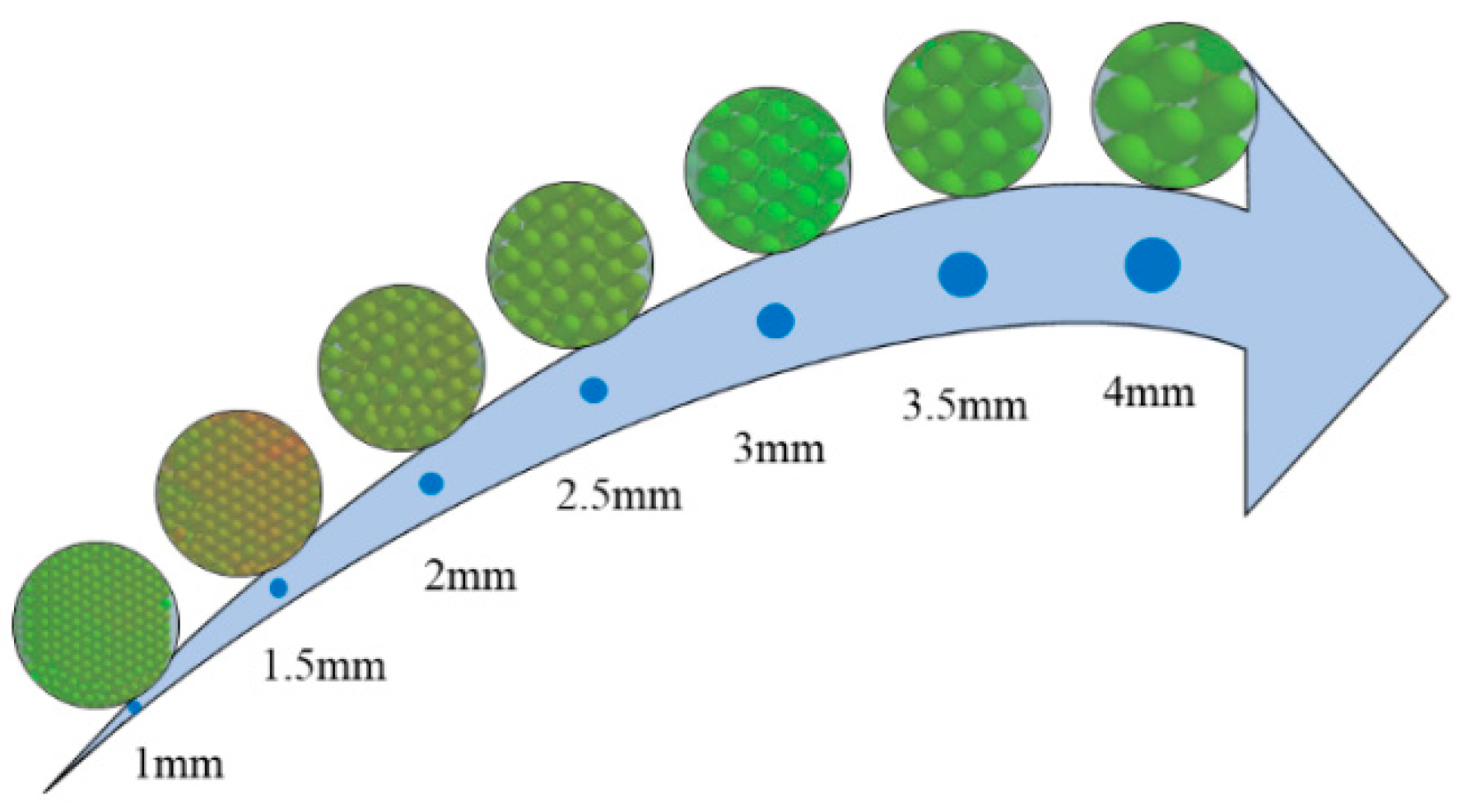
Particle size is one of the most important parameters for analysing the energy consumption of a damper. Other things being equal. The steel ball particles with particle sizes of 1mm, 1.5mm, 2mm, 2.5mm, 3mm, 3.5mm and 4mm were selected respectively. The filling effect of different particle sizes in the damper is shown in
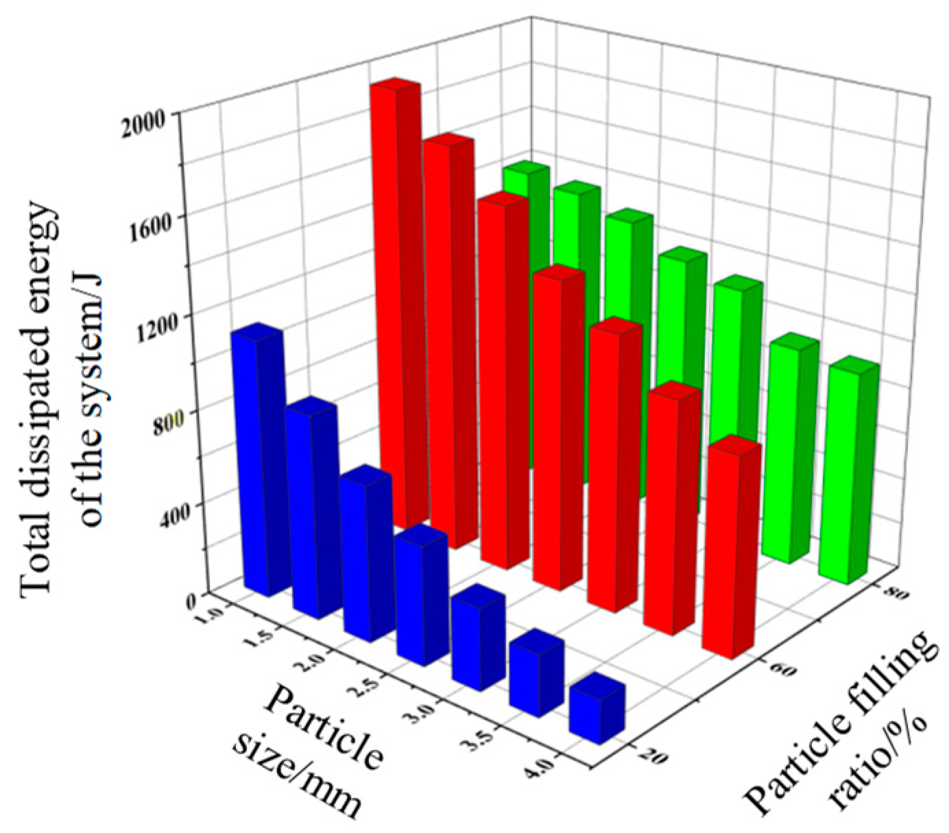
Figure 4. The effects of different filling particle sizes on the total energy dissipation of the particle system at three filling rates of 20%, 60% and 80% are investigated separately.
Figure 3.
Filling effect of different particle sizes in the damper.
Figure 3.
Filling effect of different particle sizes in the damper.
As shown in
Figure 4 and
Figure 5: at a single particle fill rate, the total dissipated energy of the particle system decreases as the particle size increases.Due to the spatial environment in which the particles are located, the larger the particle size, the smaller the number of particles in the damper cavity. This results in fewer particle collisions and therefore less total energy dissipation in the particle system. At the three particle fill rates, it is easy to see that the total energy dissipated in the particle system is greatest at 60% fill rate, next at 80% fill rate, and least at 20% fill rate.hollow pipe modal and frequency response, the pipe section is divided by a hexahedral mesh of 2 mm in size. The joint and nut are divided by tetrahedral mesh of 4 mm in size, and the pipe is fixed and supported at all four ends. The results of the natural frequency obtained from the pipeline simulation and experiment are shown in
Table 2.
Figure 2 shows the comparison of FRF from the experiment and simulation. The simulation of the first three orders of natural frequency of the pipeline system match with the experimental results, the maximum error is under 7%, and the corresponding vibration pattern is shown in
Figure 3. The reasons for that discrepancy include the accuracy of the instrument, the processing error of the pipeline, and the simplification of the four-way joint by the finite element model. Moreover, the acceleration sensor could add a small quantity of mass, and the additional mass of the longer part of the pipeline is not considered. Generally speaking, the experimental and the numerical results are in good agreement and, therefore, the accuracy of the proposed methodology was verified.
3.3.3. Effect of particle density on system energy consumption.
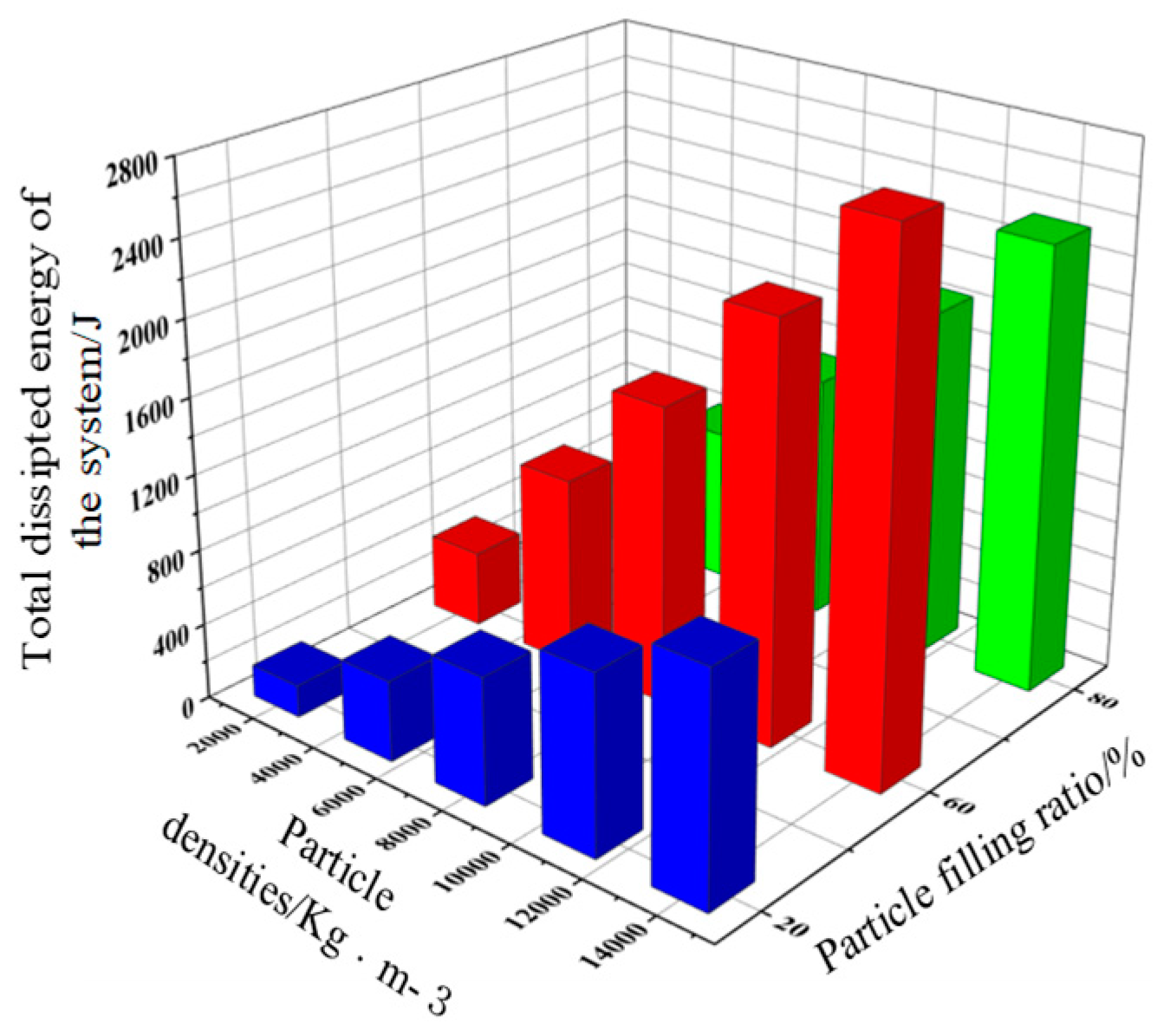
Particle density is an important parameter in simulation. Other conditions remain unchanged. The particle densities of 2000, 5000, 7850, 11000 and 14000 kg/m3 were selected.The influence of different filled particle sizes on the total energy dissipation of the granular system was investigated at three filling rates of 20%, 60% and 80%, respectively.
As shown in
Figure 6, the total energy dissipation of the pipeline particle collision damper system increases with particle density at all three fill rates. Under the same particle size condition, the mass of particles with lower density is much smaller. Under vibration conditions, the motion of the particle system is relatively loose, and the contact with the damper system as a whole is relatively small. Therefore, the overall energy consumption of the particle system is low. Whereas denser particles have a relatively large mass, the particle system moves in closer contact. The collision and friction between particles and particles, and between particles and vessel walls will be more prominent. Therefore a larger energy dissipation can be achieved.
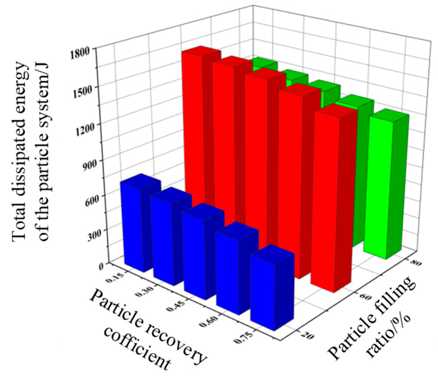
3.3.4. Effect of particle recovery coefficient on system energy consumption
The particle recovery coefficient characterises the energy dissipation effect due to the normal relative motion that occurs during collisions between particles and particles, and between particles and vessel walls [
29,
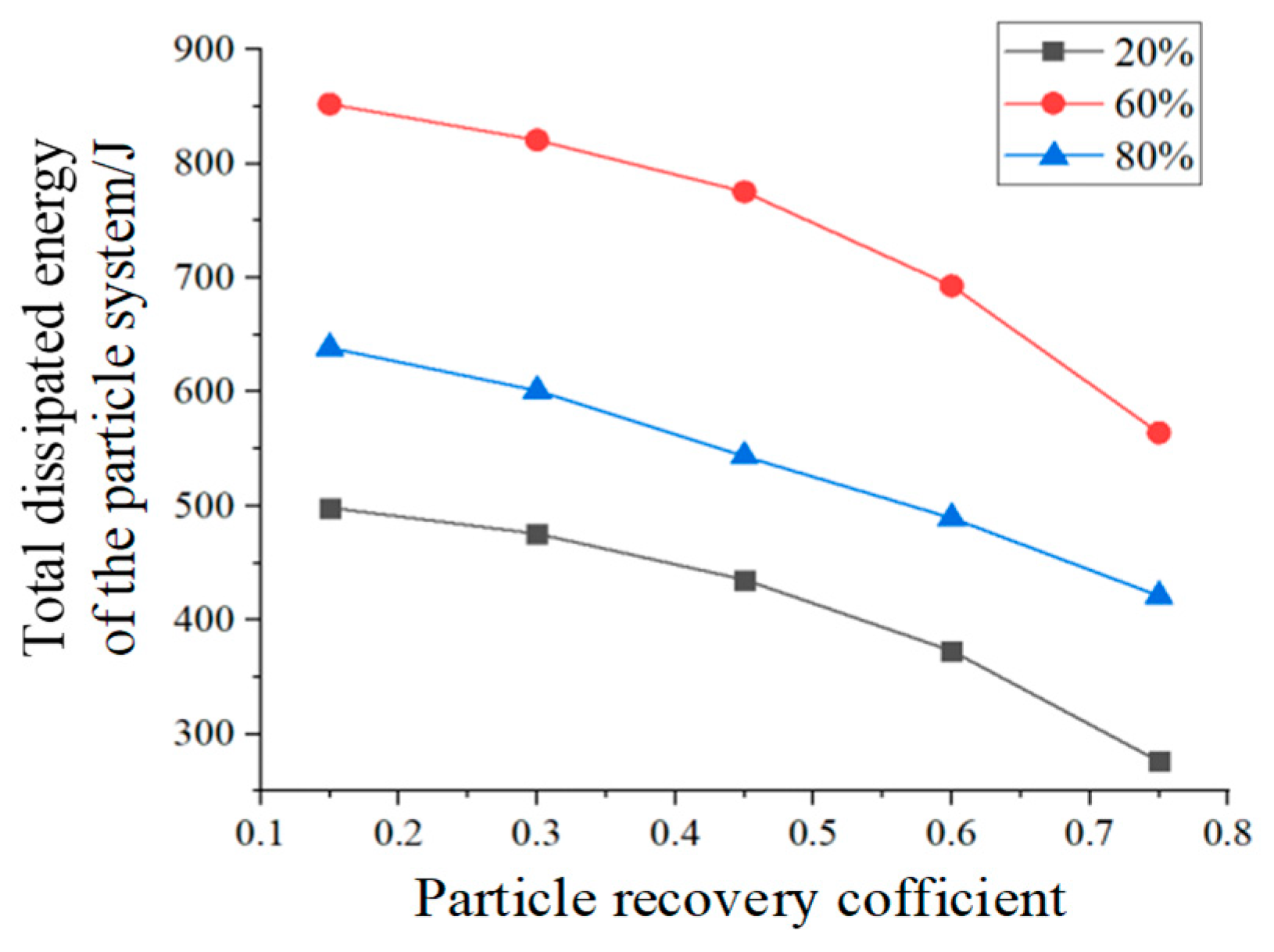
30]. It is an important index to study the energy dissipation characteristics of the particle system. Other conditions are unchanged. The particle recovery coefficients were selected as 0.15, 0.3, 0.45, 0.6, 0.75. The effects of different particle recovery coefficients on the total energy dissipation of the granular system and the total normal energy dissipation at three filling rates were obtained as shown in
Figure 7 and
Figure 8.
As shown in Figs. 7~8, with the increase of the particle recovery coefficient, both the total dissipated energy and the normal total dissipated energy of the particle system show a gradual decreasing trend. The smaller the particle recovery coefficient is, the stronger the particle recovery ability is. The greater the mechanical energy loss, the greater the overall dissipated energy of the particle system. When the particle recovery coefficients are the same and the filling ratios are different, the smaller the filling ratio of the particles, the smaller the proportion of space occupied by the particles in the damper cavity. The normal relative velocity of the particles decreases as a result of the increase in motion travel. The number of effective contacts between particles and particles, and between particles and container walls decreases. Resulting in contact collision dissipation of total energy becomes smaller. When the particle fill rate is at the more favourable value, the total energy supplied by the damper to the particle system achieves greater dissipation through the contact body system.
3.3.5. Influence of contact body friction effects on system energy consumption.
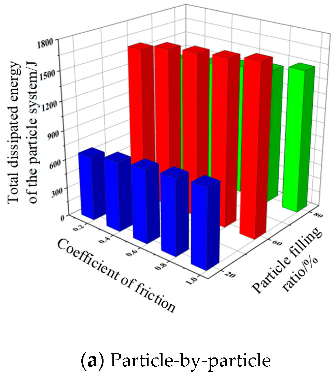
The friction coefficient is one of the important parameters affecting the energy consumption of the pellet system. [
27,
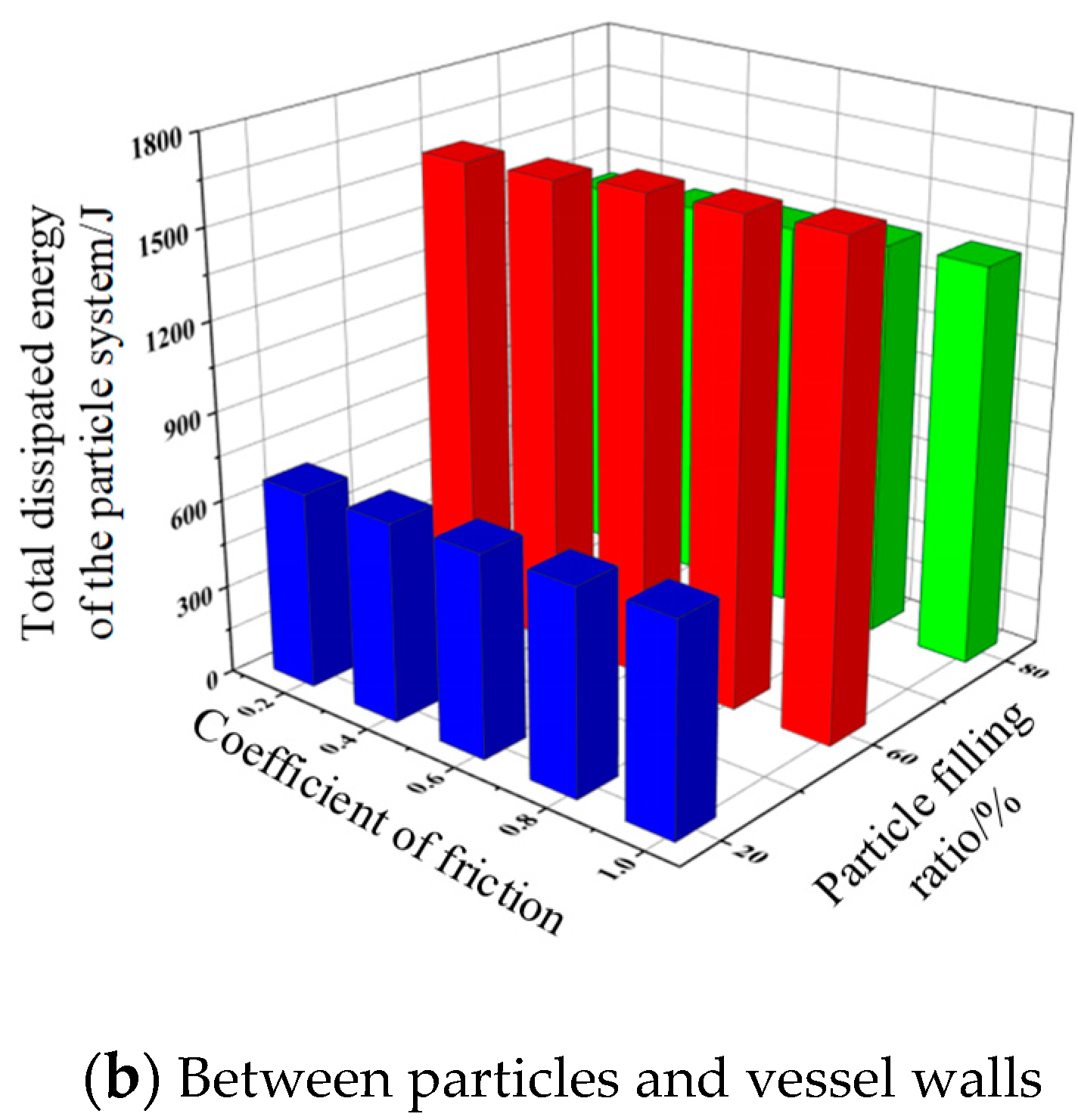
28]The friction coefficients between particles and particles were selected as 0.15, 0.35, 0.55, 0.75, 0.95. The friction coefficients between particles and container wall were 0.17, 0.37, 0.57, 0.77, 0.97. Other conditions were kept constant. The obtained laws of influence of friction coefficients between different contact bodies on the total dissipated energy of the particle system are shown in
Figure 9.
As shown in
Figure 9, the total dissipated energy of the particulate system tends to increase as the friction coefficients between particles and particles and between particles and vessel walls increase. Since the total dissipated energy of the particle system includes collision dissipated energy and friction dissipated energy. Under the same working condition, the larger the friction coefficient between particles, the larger the friction energy dissipated by friction. The total dissipated energy of the particle system will also increase.
3.3.6. Effect of damper structure on system energy consumption.
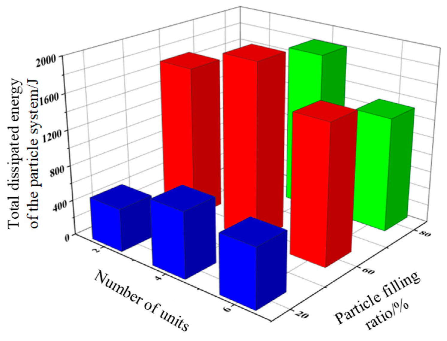
The energy dissipation characteristics of pipeline particle collision dampers also change depending on the damper structure. Particle collision dampers with two-unit, four-unit and six-unit damper cell structures are selected. The effects on the total energy dissipation of the particle system are investigated at three fill rates of 20%, 60% and 80%, respectively.
As shown in
Figure 10, the total energy dissipation value of the particle system increases and then decreases with the number of damper units when the particle fill rate is the same. When the damper is a two-unit structure, the space in a single cavity of the pipe particle collision damper is larger. The free motion travel of the particles in the cavity is large. The effective contact energy dissipation between particles and particles, and particles and vessel wall is reduced. As the number of damper units increases, the space in the individual cavities of the damper becomes smaller. The travelling distance of the particle system becomes shorter. The energy dissipated due to collision and friction increases. When the space in the individual cavities of a pipeline particle collision damper is small, the motion of the particles inside the vessel is limited. The ability to dissipate energy by collision and friction between contacting bodies is reduced. The total dissipated energy is then reduced.
3.4. Analysis of the effect of external excitation parameters of a pipe particle damper
3.4.1. Effect of excitation frequency on system energy consumption.
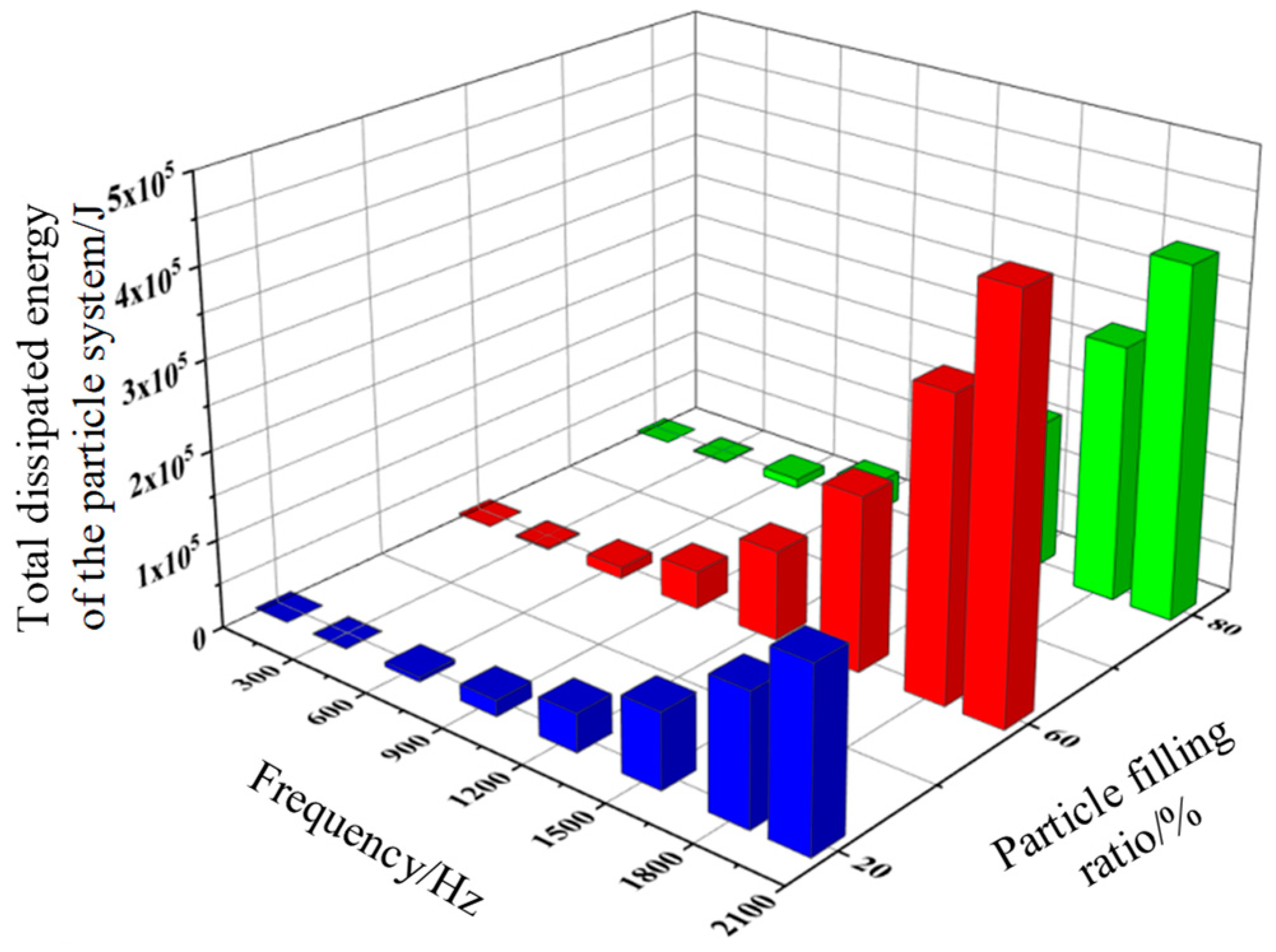
The pipeline particle damper is capable of energy dissipation in a wide frequency domain. A sinusoidal excitation is applied in the x-direction of the damper. The excitation frequencies are chosen to be 50, 300, 600, 900, 1200, 1500, 1800, and 2000 Hz. All other conditions remain unchanged.
Figure 11 shows that the total dissipated energy of the system increases with the increase of the excitation frequency. The total energy dissipated by the particle system at higher excitation frequencies increases much more than at lower excitation frequencies. The higher the excitation frequency, the greater the number of vibrations per unit of time for a pipeline particle damper. The number of particle-particle and particle-vessel wall interactions increases. The total energy consumed by collision and friction increases. At the same time, at different filling rates, the number of particles will also affect the total energy consumption of the particle system.
3.4.2. Effect of amplitude displacement on system energy consumption.
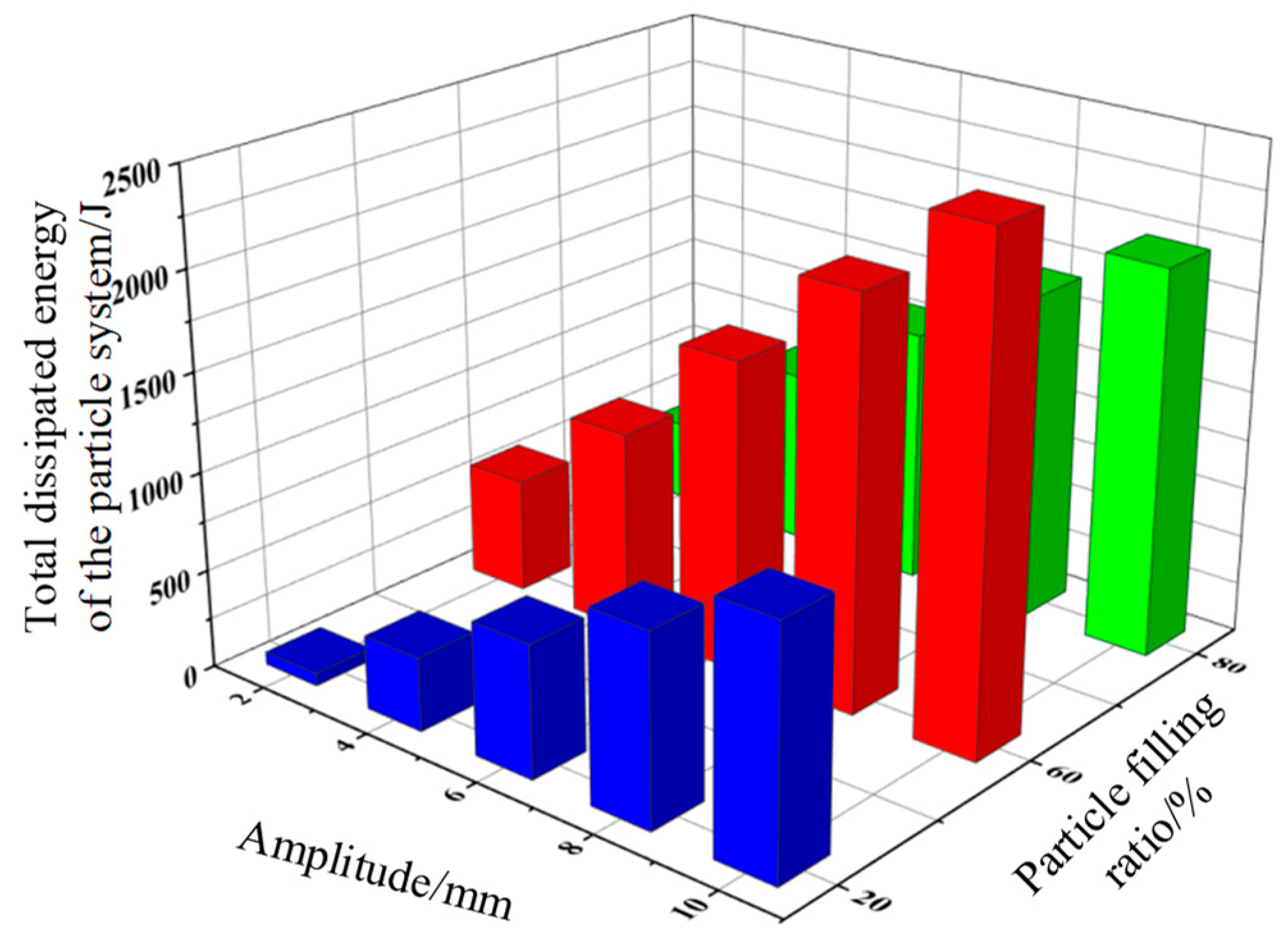
In order to investigate the effect of the displacement amplitude of the pipe particle collision damper on the total energy dissipation of the particle system. Other conditions remain unchanged. Different displacement amplitudes were applied to the damper in the x-direction. The displacement amplitudes are 2 mm, 4 mm, 6 mm, 8 mm, and 10 mm.
As shown in
Figure 12, as the displacement amplitude of the damper structure increases, the total dissipated energy of the particle system becomes larger and larger. This is due to the fact that the displacement amplitude of the damper structure changes the motion of the particles inside the vessel. The intensity of the motion of the particles in the damper cavity increases with the amplitude of the displacement of the structure. The momentum exchange between the particles and the damper system increases. The total dissipated energy of the particle system becomes larger. For a single displacement amplitude, the total dissipated energy of the particle system increases with the filling rate. The maximum value of total dissipated energy of the particle system is found at an amplitude displacement of 10 mm and a particle fill rate of 60%.
4. Experimental verification on the damping performance of the pipeline system
4.1. Test system set-up
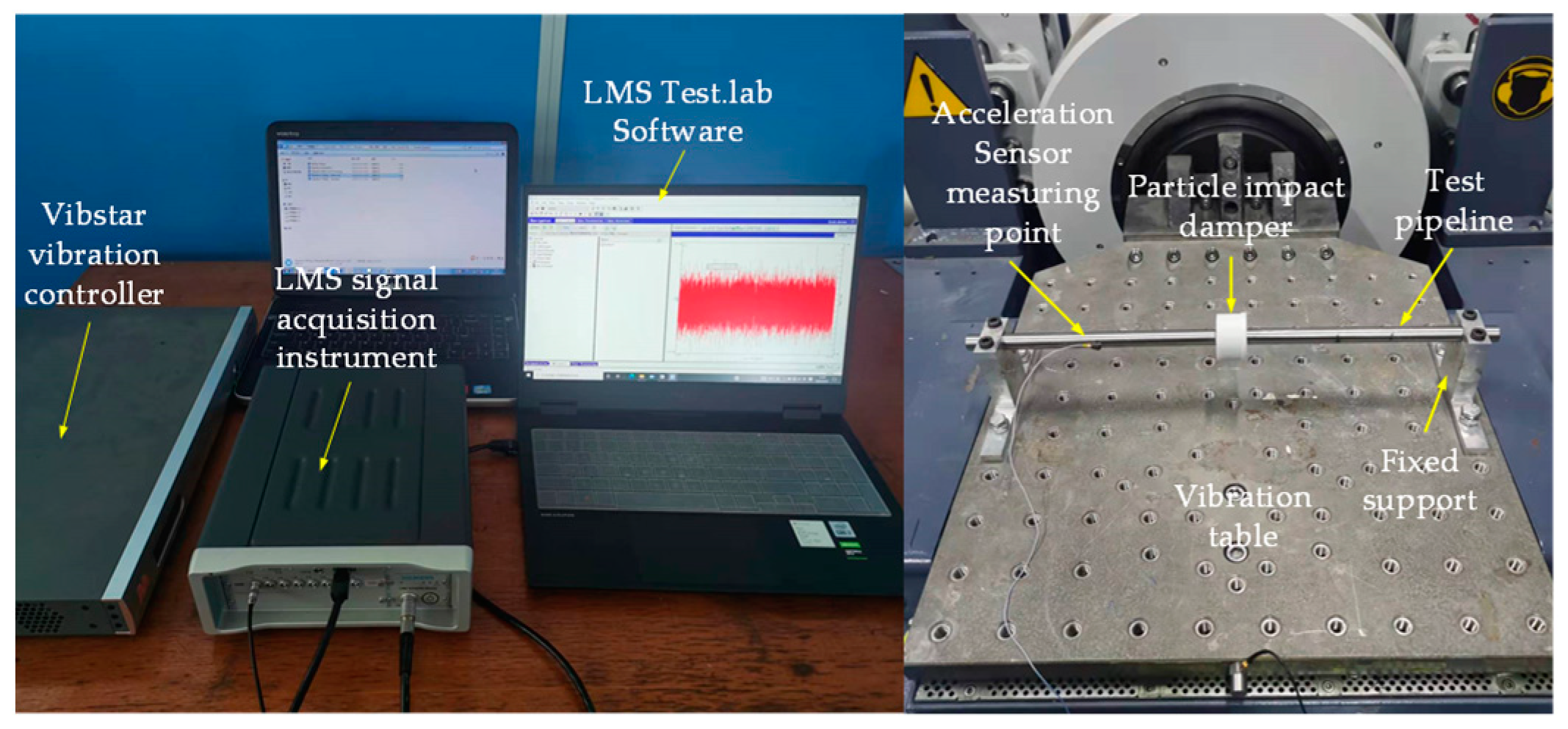
To verify the vibration damping effect of particle collision damper in pipelines. A test platform for particle collision damper pipeline vibration characteristics was built. The random excitation and simple harmonic excitation tests were performed on the cantilever pipeline with and without particle collision damper. The vibration signals of the pipeline were collected using the LMS vibration test and analysis system. the shaker test layout are shown in
Figure 13.
4.2. Damping performance test of particle damping line under simple harmonic excitation of foundation
4.2.1. Influence of different materials of four-unit dampers on the vibration damping performance of pipelines.
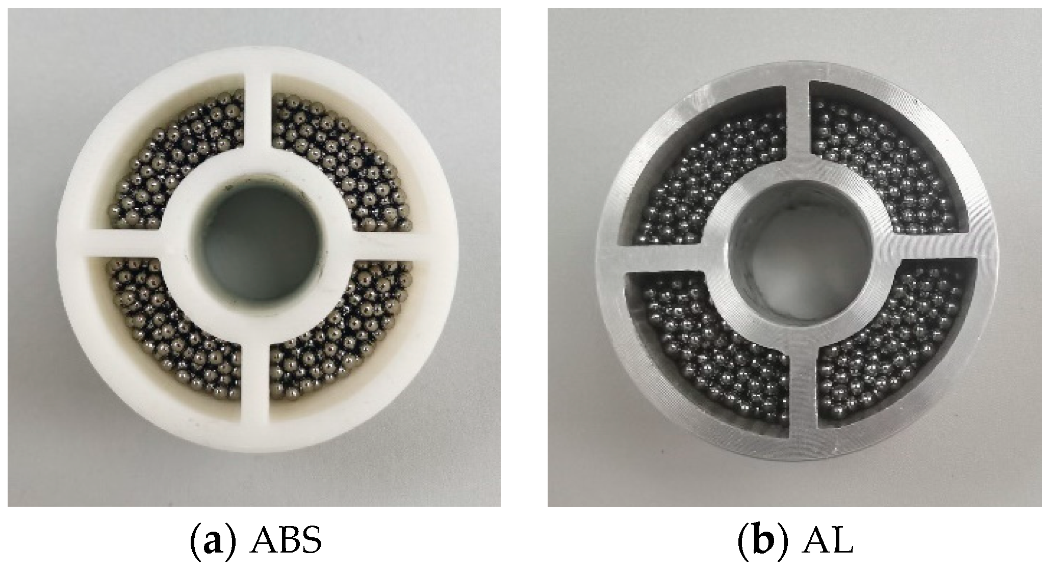
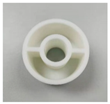
A four-cell particle damper made of two materials is shown in
Figure 14. The damper is filled with steel ball particles of 2 mm particle size with 60% fill rate.
The experimental setup of the particle damper attached to the cantilever tube is shown in
Figure 13. The frequency range of the sinusoidal swept excitation is 10-2000 Hz, and the resonance frequencies of the bare pipeline and the four-unit particle damper with different materials are obtained. The corresponding first-order resonance frequency is chosen as the excitation frequency of sinusoidal frequency. The first order resonance frequency was chosen to be the sinusoidal frequency, and the excitation frequencies were 83 Hz, 46 Hz and 43 Hz, respectively, and the comparative time and frequency domain responses of the pipeline system before and after the addition of the four-unit particulate collision damper with different materials were obtained as shown in
Figure 15.
As shown in
Figure 15,the time domain and frequency domain responses of the tubing with two additional particle crash damper materials are significantly reduced compared to that of the bare pipeline. The first-order frequency of the four-unit particle collision damper made of ABS and aluminium alloy is reduced by 83.66% and 85.29%, respectively, compared with that of the bare pipeline. The first-order amplitude of the four-unit particle crash damper made of aluminium alloy decreases by about 9.97% compared with that made of ABS. This shows that the particle collision damper with these two materials can achieve good damping effect, and the four-unit damper made of aluminium alloy has better damping effect.
5. Conclusions
Piping systems as the research object. Particle damping technology is introduced into the pipeline system. The energy dissipation mechanism of particle collision damping is analyzed via numerical calculation and experimental testing. The particle collision damper of piping system is designed. The effects of damper material and structure, external excitation and other parameters on the energy dissipation characteristics of particle collision damping are revealed via numerical calculations and experiments. The vibration suppression test of particle damping on pipeline system is completed. The main conclusions of this paper are as follows:
1. The total energy dissipated in the particle system shows a trend of increasing and then decreasing with the increase of filling rate. The total dissipated energy of the particle system is the largest when the filling rate is 60%. When the damper space is a constant value, the number of particles filled and energy dissipated in the particle system decreases with increasing particle size. The total dissipated energy of the particle system increases with the increasing of particle density.
2. The total dissipated energy of the particle system increases with increasing particle density, increasing particle-particle and particle-vessel wall friction coefficients, and decreasing recovery coefficients. The total energy dissipated in the particle system shows a tendency to increase and then decrease with the increase of the number of damper units, and the total dissipated energy in the particle system is the largest when the damper is a four-unit structure.
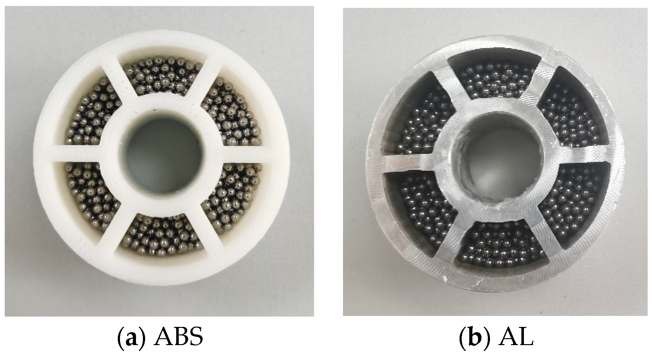
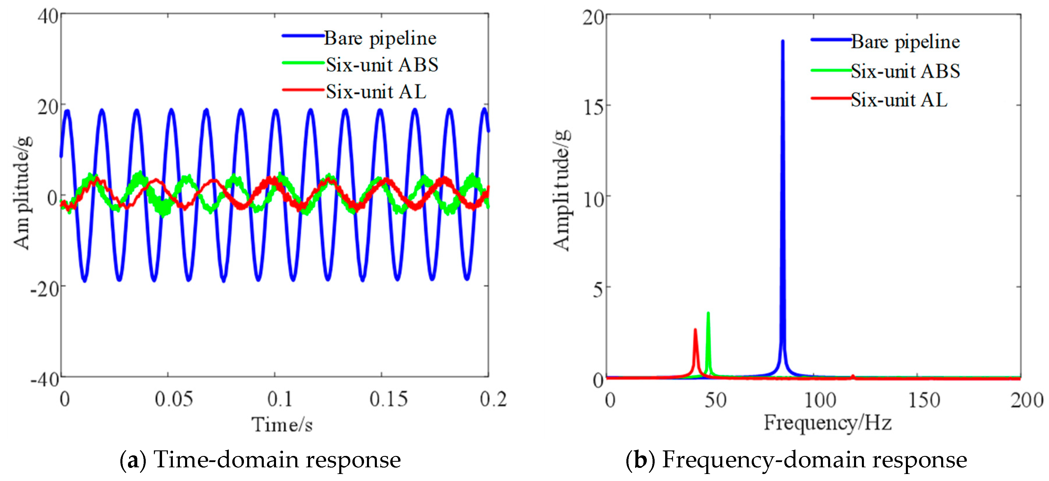
3. The total dissipated energy of the particulate system increases with increasing excitation frequency, amplitude displacement and number of vibrations of the damper structure. The frequency domain amplitude of the additional aluminum alloy damper piping decreases by 9.97% and 19.61% for the four-unit and six-unit damper configurations, respectively, compared with that of the ABS. This indicates that the damping effect of the aluminum alloy particle dampers with different cell structures is better than that of the ABS damper.
4. For both ABS and aluminum alloy damper structures, the frequency domain amplitudes of the additional four-unit damper pipeline are smaller than that of the six-unit one. This indicates that the four-unit particle damped damper has better damping effect on the pipeline system. Under the basic random excitation, the damping effects of the two materials and two-unit structures attached to the damper on the pipeline have the same pattern.
Funding
This research was funded by Natural Science Foundation of Shandong Province (No. ZR2020ME121).
Institutional Review Board Statement
Not applicable.
Informed Consent Statement
Not applicable.
Data Availability Statement
The data used to support the findings of this study are available from the corresponding author upon request.
Conflicts of Interest
The authors declare no conflict of interest.
References
- GAO P X, YU T, Zhang Y L, et al. Vibration analysis and control technologies of hydraulic pipeline system in aircraft: A review[J]. Chinese Journal of Aeronautics, 2021, 34(4): 83-114. [CrossRef]
- Xiao Wangqiang, Lu Dajun, Song Liming, Guo Haiquan, Yang Zhe. Influence of particle damping on ride comfort of mining dump truck[J]. Mechanical Systems and Signal Processing, 2020, 136(C). [CrossRef]
- Lu Z, Lu X L, Masri S F. Studies of the performance of particle dampers under dynamic loads[J]. Journal of Sound and Vibration, 2010, 329(26): 5415-5433. [CrossRef]
- Shah B M, Pillet D, Bai X M, et al. Construction and characterization of a particle-based thrust damping system[J]. Journal of Sound and Vibration, 2009, 326(3-5): 489-502. [CrossRef]
- Cui Z Y, Wu J H, Chen H L, et al. A quantitative analysis of the energy dissipation mechanism of the non-obstructive particle damping technology[J]. Journal of Sound and Vibration, 2011, 330(11): 2449-2456. [CrossRef]
- Meyer N, Seifried R. Numerical and experimental investigations in the damping behavior of particle dampers attached to a vibrating structure[J]. Computers & structures, 2020, 238: 106281. [CrossRef]
- Jin G, Zhao Z H, Liu B B, et al. Design of a particle damper and experimental study on vibration damping of the pipeline[J]. Advances in Mechanical Engineering, 2021, 13(9): 1-14. [CrossRef]
- Zhang, L.X.; Huang, W.H.; Tijsseling, A.S. Research Progress on fluid structure coupling vibration of fluid transmission pipeline. J. Hydrodyn. 2000, 15, 366–379. [Google Scholar]
- Liu, G.; Li, Y. Vibration analysis of liquid-filled pipelines with elastic constraints. J. Sound Vib. 2011, 330, 3166–3181. [Google Scholar] [CrossRef]
- Zhou D, Chen G, Liu MH, et al. Study and expermental verification on a dynamic vibration absorber with frequency adjustable. Noise Vib Control 2015; 35: 217–221.
- Panossian, H.V. Structural Damping Enhancement Via Non-Obstructive Particle Damping Technique. J. Vib. Acoust. 1992, 114, 101–105. [Google Scholar] [CrossRef]
- Xu, Z.; Wang, M.Y.; Chen, T. Particle damping for passive vibration suppression: numerical modelling and experimental investigation. J. Sound Vib. 2005, 279, 1097–1120. [Google Scholar] [CrossRef]
- Xu, Z.; Wang, M.Y.; Chen, T. An Experimental Study of Particle Damping for Beams and Plates. J. Vib. Acoust. 2004, 126, 141–148. [Google Scholar] [CrossRef]
- Liu W, Cao G, Zhai HB, et al. Sensitivity analysis and dynamic optimization design of supports’ positions for engine pipelines. J Aerosp Power 2012; 27: 2756–2762.
- Li X and Wang, SP. Vibration control analysis for hydraulic pipelines in an aircraft based on optimized clamp layout. J Vib Shock 2013; 32: 14–20.
- Yin ZY and Chen, YN. Finite element an analysis and experimental measurement of stiffness of hoop. J Aerosp Power 1999; 14: 68–71+ 110.
- He YT, Yang SH and Feng LF. On the determination of fixture intervals of pipe hoops of aircraft ground pressure refueling system. Mech Sci Technol 2000; 5: 726–728.
- Ahmadi N and Ko˜rgesaar, M. Analytical approach to investigate the effect of gas channel draft angle on the performance of PEMFC and species distribution. Int J Heat Mass Transf 2020; 152: 119529. [CrossRef]
- Wang J, Chen G, Zheng QH, et al. Effect of clamp on aircraft hydraulic pipeline dynamic stress. Aeronaut Comput Tech 2014; 44: 64–67.
- Lu QF, Zhang WH and Zhang Q. Layout design optimization of component structure with random vibration response, Acta Aeronaut Astronaut Sin 2010; 31: 1769–1775.
- Zhu JH and Zhang, WH. Maximization of structural natural frequency with optimal support layout. Struct Multidiscip Optim 2006; 31: 462–469. [CrossRef]
- Panossian, H.V. Structural Damping Enhancement Via Non-Obstructive Particle Damping Technique. J. Vib. Acoust. 1992, 114, 101–105. [Google Scholar] [CrossRef]
- Panossian, H. Non-Obstructive Particle Damping: New Experiences and Capabilities. 49th AIAA/ASME/ASCE/AHS/ASC Structures, Structural Dynamics, and Materials Conference16th AIAA/ASME/AHS Adaptive Structures Conference10t. LOCATION OF CONFERENCE, United StatesDATE OF CONFERENCE;
- Simonian, SS. Particle beam damper. Proc SPIE Int Soc Opt Eng 1995;2445:149–60.
- Johnson, CD. Design of passive damping systems. J Mech Des 1995;117 (B):171–6. [CrossRef]
- Chen, T.; Mao, K.; Huang, X.; Wang, M.Y. Dissipation mechanisms of nonobstructive particle damping using discrete element method. SPIE's 8th Annual International Symposium on Smart Structures and Materials. LOCATION OF CONFERENCE, COUNTRYDATE OF CONFERENCE; pp. 294–301.
- Fleissner, F.; Gaugele, T.; Eberhard, P. Applications of the discrete element method in mechanical engineering. Multibody Syst. Dyn. 2007, 18, 81–94. [Google Scholar] [CrossRef]
- Hertz, H. Gesammelte Werke. Vaduz: Sändig-Reprint-Verlag; 1984.
- Lankarani HM, Nikravesh PE. A contact force model with hysteresis damping for impact analysis of multibody systems. J Mech Des 1990;112 (3):369–76. [CrossRef]
- Gonthier, Y.; McPhee, J.; Lange, C.; Piedbœuf, J.-C. A Regularized Contact Model with Asymmetric Damping and Dwell-Time Dependent Friction. Multibody Syst. Dyn. 2004, 11, 209–233. [Google Scholar] [CrossRef]
Figure 1.
Particle-vessel contact.
Figure 1.
Particle-vessel contact.
Figure 2.
Total dissipated energy of the system with different particle filling ratio.
Figure 2.
Total dissipated energy of the system with different particle filling ratio.
Figure 4.
Total dissipated energy of granular system with the same particle size.
Figure 4.
Total dissipated energy of granular system with the same particle size.
Figure 5.
Total number of particle collisions for different particle sizes.
Figure 5.
Total number of particle collisions for different particle sizes.
Figure 6.
Total dissipated energy of the system for different particle densities.
Figure 6.
Total dissipated energy of the system for different particle densities.
Figure 7.
Total dissipated energy of the particle system with different particle recovery coefficients.
Figure 7.
Total dissipated energy of the particle system with different particle recovery coefficients.
Figure 8.
Normal dissipated energy values with different particle recovery coefficients.
Figure 8.
Normal dissipated energy values with different particle recovery coefficients.
Figure 9.
Total dissipated energy of particles with different friction coefficients between contact bodies.
Figure 9.
Total dissipated energy of particles with different friction coefficients between contact bodies.
Figure 10.
Total dissipated energy of the particle system with different numbers of damper units.
Figure 10.
Total dissipated energy of the particle system with different numbers of damper units.
Figure 11.
Total dissipated energy of the particle system at different excitation frequencies.
Figure 11.
Total dissipated energy of the particle system at different excitation frequencies.
Figure 12.
Total dissipated energy for different displacement amplitudes.
Figure 12.
Total dissipated energy for different displacement amplitudes.
Figure 13.
Experimental setup of the vibration test.
Figure 13.
Experimental setup of the vibration test.
Figure 14.
Filling effect of four-unit granular damper with two materials.
Figure 14.
Filling effect of four-unit granular damper with two materials.
Figure 15.
Vibration response of a four-cell particle damper line with two additional materials.
Figure 15.
Vibration response of a four-cell particle damper line with two additional materials.
Figure 16.
Filling effect of six-unit granular damper with two materials.
Figure 16.
Filling effect of six-unit granular damper with two materials.
Figure 17.
Vibration response of a six-cell particle damper line with two additional materials.
Figure 17.
Vibration response of a six-cell particle damper line with two additional materials.
Table 1.
Structural diagram of pipeline particle collision damper.
Table 2.
Structural parameters of pipeline particle impact damping vibration damper.
Table 2.
Structural parameters of pipeline particle impact damping vibration damper.
| Inner diameter |
Outer diameter |
Vessel height |
Wall plate thickness |
Cover plate thickness |
| 16.5mm |
46mm |
28mm |
3mm |
1mm |
Table 3.
Material parameters.
Table 3.
Material parameters.
| Material |
Density(ρ)/kg⋅m-3 |
Elasticity moduls(E)/GPa |
Poisson ratio(μ) |
| AISI1045 |
7850 |
200 |
0.3 |
| 1100AL |
2800 |
68.9 |
0.33 |
Table 4.
Contact parameter.
Table 4.
Contact parameter.
| Contact |
Coefficient of recovery |
Coefficient of static friction |
coefficient of rolling friction |
| AISI1045-AISI1045 |
0.45 |
0.15 |
0.15 |
| AISI1045-1100A |
0.45 |
0.17 |
0.001 |
Table 5.
Number of particles and mass ratio corresponding to different filling ratio.
Table 5.
Number of particles and mass ratio corresponding to different filling ratio.
| Particle filling ratio/% |
Number of particles |
Mass ratio/% |
| 10 |
203 |
6.68 |
| 20 |
406 |
13.35 |
| 30 |
609 |
20.03 |
| 40 |
812 |
26.73 |
| 50 |
1015 |
33.38 |
| 60 |
1218 |
40.05 |
| 70 |
1421 |
46.73 |
| 80 |
1624 |
53.40 |
| 90 |
1827 |
60.08 |
| 100 |
2030 |
66.75 |
|
Disclaimer/Publisher’s Note: The statements, opinions and data contained in all publications are solely those of the individual author(s) and contributor(s) and not of MDPI and/or the editor(s). MDPI and/or the editor(s) disclaim responsibility for any injury to people or property resulting from any ideas, methods, instructions or products referred to in the content. |
© 2023 by the authors. Licensee MDPI, Basel, Switzerland. This article is an open access article distributed under the terms and conditions of the Creative Commons Attribution (CC BY) license (http://creativecommons.org/licenses/by/4.0/).
