1. Introduction
Blood flow in arteries can be described mathematically by the Navier-Stokes equations in three dimensions (3D). However, numerical approximations for three-dimensional models are computationally expensive. Therefore, the simpler one-dimensional (1D) models are considered, which provide a realistic description of certain parts of the cardiovascular system and also provide boundary conditions for the more complex three-dimensional models. A simplified 1D model that describes the blood flow in arteries is given by the following system of partial differential equations (see e.g. [
1])
where
is the cross-sectional area of the vessel at spatial position
x and time
t with
being the radius,
is the mean blood velocity in the axial direction,
is the blood density, assumed to be constant and equal to
,
is the internal pressure and
is the friction force per unit length. The present work is restricted to the inviscid limit where
.
Several expressions can be found in the literature to describe the pressure. In the present work we use the algebraic expression proposed in [
2]:
where the external pressure
, the coefficient
stands for the arterial stiffness and is supposedly constant and
is the vessel cross-sectional area at rest, which may be variable in the case of some pathologies.
We refer to equations (
1) as the system
. Such equations are an example of a
system of balance laws
where
correspond to the vector of unknowns, flux function and source term, respectively. In order to analyse the characteristic information it is convenient to write the system in the non-conservative form
where
is the Jacobian matrix of the flux function with eigenvalues
and the corresponding right eigenvectors are given by
Here,
is the Moens-Korteweg wave speed.
It is well known that solutions of balance laws may contain discontinuities, even for smooth initial data. Consequently, the solutions of such systems must be considered in weak sense. Moreover, the weak solutions may not be unique, then it is necessary to impose an additional admissibility criterion or entropy conditions to select among the possible solutions, the one that is physically relevant [
3]. In particular, the system
admits the entropy inequality
where
is the extended entropy pair introduced in [
4]:
and
is the entropy pair
given by
Using the entropy pair we may obtain the entropy variables
with the corresponding entropy potential
In the extended case, we have
Systems as (
3) are of special interest because of the delicate balance that must exist between the convective term and the source term during the time evolution. Specifically, the steady-states solutions for the system (
3) are the solutions
which are time-independent. Thus, steady-state solutions satisfy the system
In particular, the system
admits the following steady-state solution, known as the
(non-zero pressure) man-at-eternal-rest steady state or
dead-man equilibrium [
5]:
When
, the
(zero pressure) man-at-eternal-rest steady state is obtained, namely
It is crucial that numerical methods to approximate steady-state solutions also satisfy a discrete version of (
11). Such methods are termed
well-balanced schemes.
2. Numerical method
Since, in general, it is not possible to find an analytical solution of the system (
3), it is imperative to approximate the solution numerically. To this end, we consider a semi-discrete finite volume scheme for (
3) on a uniform spatial mesh with nodes
,
:
where
is the cell average on
,
is the numerical flux associated with
and
is a discretization of the source term. It should be noted that the first term on the right-hand side corresponds to the discretisation of the spatial derivative
. The discretization of the time derivative will be discussed later.
The scheme (
14) is
entropy stable with respect to the entropy pair
if it satisfies a discrete version of the entropy inequality (
5), that is,
for some
numerical entropy flux consistent with the entropy flux
. If equality holds in (
15), then the scheme (
14) is called
entropy conservative.
From now on, we use
to denote, respectively, the jump of
a across the interface
and the arithmetic mean of
a quantity.
In this work we will used a numerical flux of the form [
7]:
where
- (i).
-
is the second order and entropy conservative flux for the homogeneous case of (
3) given by
with the corresponding numerical entropy flux
The numerical flux (
17) was obtained in [
8] from the condition (see [
6])
- (ii).
is the matrix of right eigenvectors of the Jacobian matrix
being evaluated at the average state
,
is a Roe-type matrix and
y
denoting, respectively, the left and right limiting values of the
scaled entropy variables at interface
, obtained by ENO reconstruction. The choice of this ENO method is due to the fact that it satisfies the so-called
sign property [
9]:
which will be useful in proving entropy stability of the flux (
16).
The discretization of the second component of the source term
is performed using the simple and well-known second-order centered difference approximation
Thus, the discretization of the source term yields
where
denotes the discrete approximation of
.
3. Theoretical results and numerical experiments
In this section it is shown that the scheme (
14) with numerical flux (
16) and discretization of the source term (
21) is entropy stable and well- balanced. The proof is similar to that developed for the Saint-Venant equations and the relativistic magnetohydrodynamics equations in [
10] and [
11], respectively. Then, some examples are included to check that the numerical scheme verifies these properties at the discrete level.
Theorem 1. The numerical scheme (14) with numerical flux (16) and discretization of the source term (21) satisfies the following properties:
-
(i)
-
It is entropy stable, i.e., satisfies the discrete entropy inequality (15), where is the entropy function given by (6) and the corresponding numerical entropy flux is
-
(ii)
-
it preserves the discrete version of the man-at-eternal-rest (12), this means that given the initial data
with C a constant, then the solution obtained with the scheme (14) satisfies
Proof. Let us first prove entropy stability. Multiplying (
14) by
yields
The left-hand side of (
26) gives
We now turn to the right-hand side. Using (
10), the numerical flux
explicitly given by (
17), the equation (
18) and the definition of
(18), we get
To deal with the factor (28) in parenthesis, we take into account the definition of the scaled entropy variables and (
24) to obtain
Using the discretization of the source term bive by (
21) we can rewrite (29) as
Inserting (
30), (
31), (
32) and (
33) into (
26) an dusing the definition of
given by (
22) we get
Therefore,
where the last inequality is obtained by using the sign property. Summing up,
which proves entropy stability.
We next show the second part of the theorem. From (
25) it follows easily that
The second equality implies that
is constant, thus
, and consequently the diffusion term in (
16) vanishes. On account of this remark, we have
. Hence,
the last equality being a consequence of (
25). □
Discretización temporal
To discretize the temporal derivative in (
14), the explicit second-order strong stability preserving Runge-Kutta method SSPRK (Heun’s method) will be used. This method is described by the following steps
where
with
and
given by (
16) and (
21), respectively. In order to guarantee that the explicit scheme obtained to be stable, the time and space discretization steps must obey the CFL condition. For this purpose, the value of
is computed adaptively for each step. More exactly, the solution
at
is calculated from
by using the time step
, where
is an estimate of the maximal characteristic velocity for
. All numerical experiments are carried out with a CFL number of
.
3.1. Numerical tests
In this section, some examples are presented to validate that the scheme correctly captures the steady-state solutions of system (
1) and to verify that it is entropy stable at discrete level. In all examples transmissive boundary conditions are imposed.
3.1.1. Ejemplo 1.
In the first example taken from [
12], we consider three different configurations for the Riemann problem with initial data
with the spatial domain of length
and
the point where the discontinuity is located. The numerical solutions are computed on a mesh with
uniform cells and for comparison purposes reference solutions are computed on a refined mesh with 3200 uniform cells. The other parameters are
,
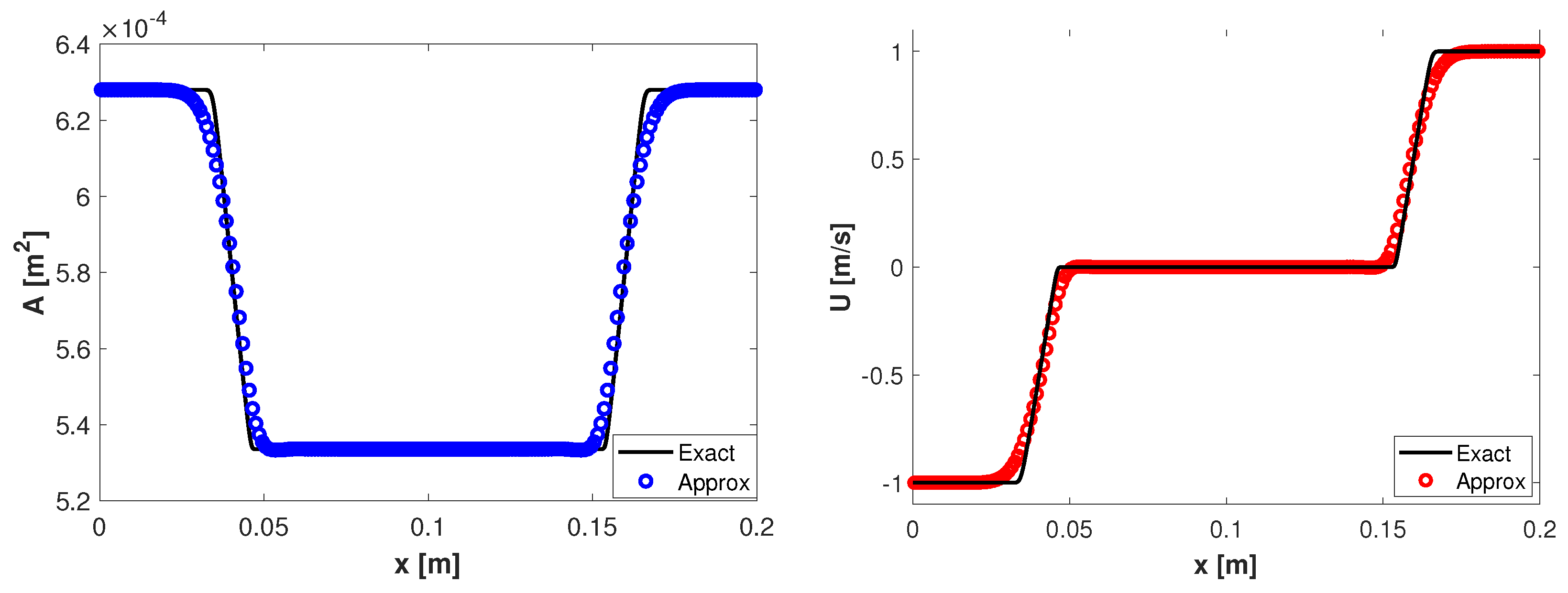
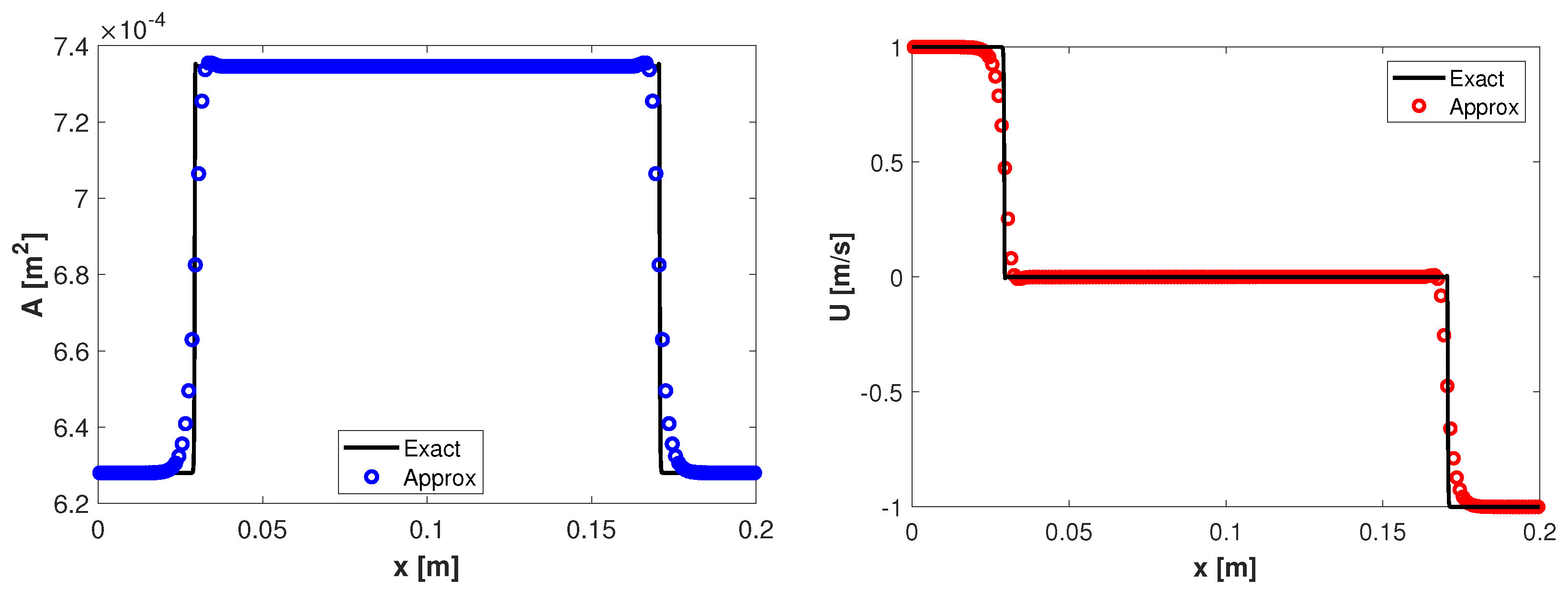
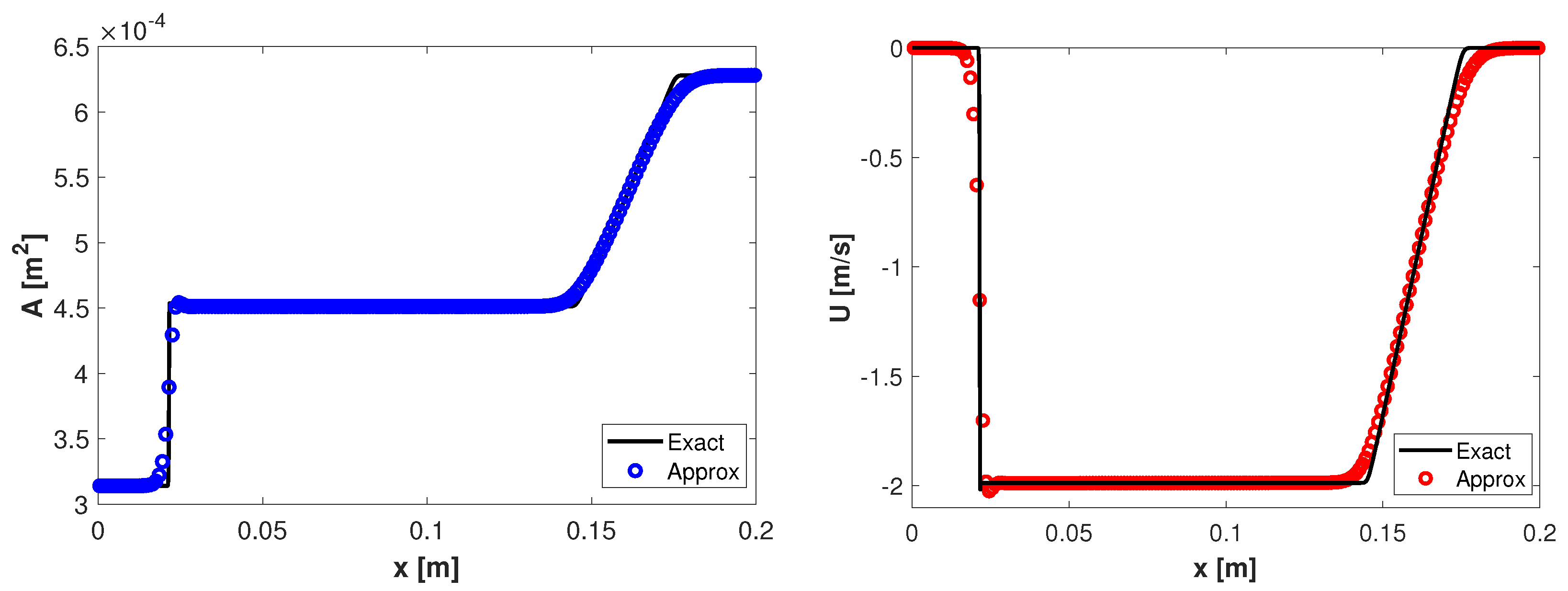
along with different configurations of the initial data to obtain different types of waves. One can observe in
Figure 1 the two rarefactions obtained at the final time
for the initial data
,
. In
Figure 2 it is observed that the scheme can capture the two shocks waves obtained at the time
for the initial data
,
. The third configuration is
,
and the results at the time
are displayed in
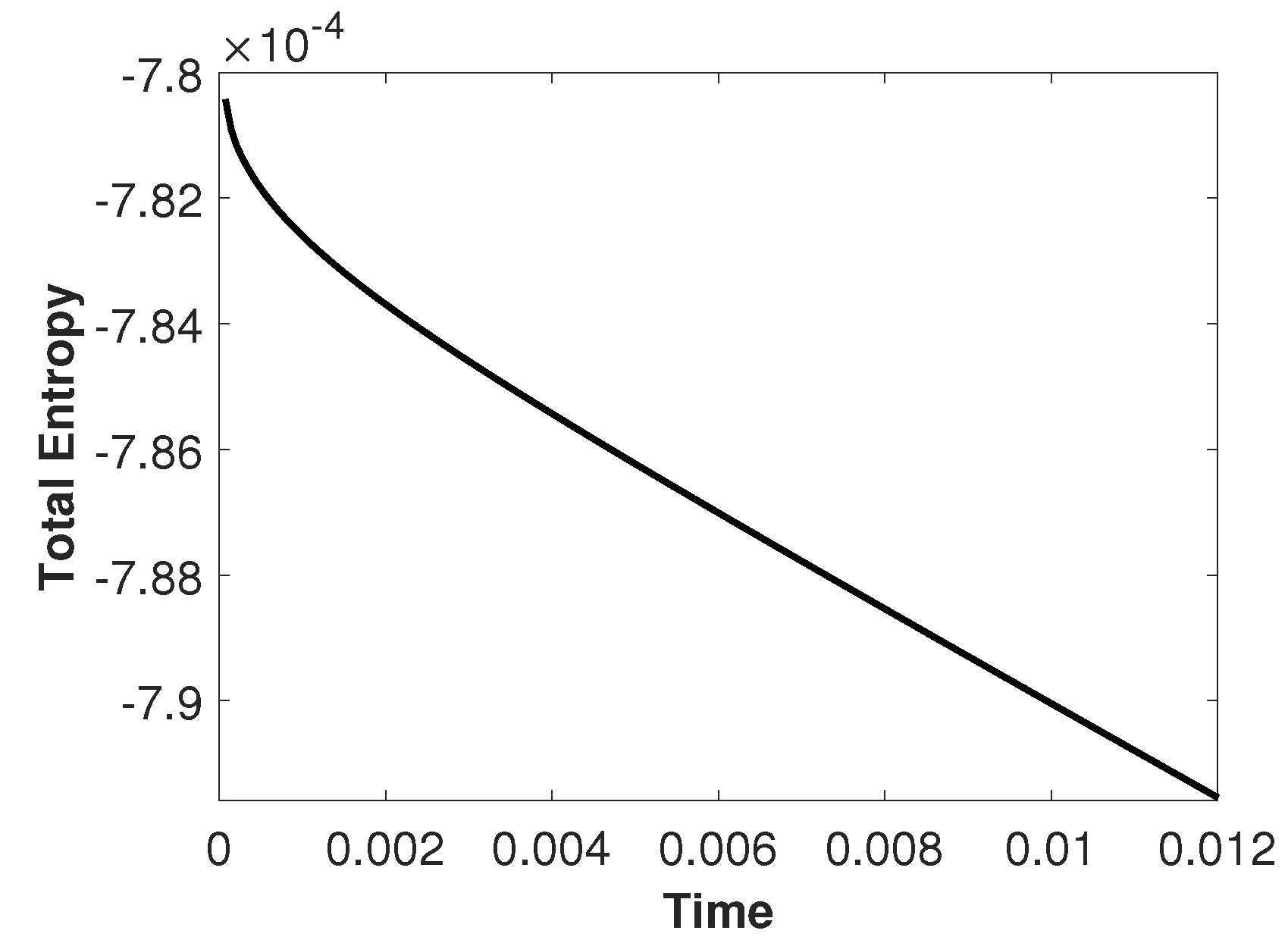
Figure 3. In this case, the solutions develop a left discontinuity follows by a right rarefaction. Due to the presence of two types of waves we also present in
Figure 4 the total entropy
As expected, this quantity decreases over time, that is, the scheme is entropy stable at the discrete level.
3.1.2. Ejemplo 2.
The purpose of this test problem taken from [
13] is to check that the proposed scheme preserves the zero pressure man-at-eternal-rest steady state (
13) at a discrete level. The configuration exhibits with no flow and includes a change in the section of the artery. This is the case for a dead man with an aneurism. The initial conditions are
and
, where
with
,
,
,
,
,
and
. The computational domain is
and
. The numerical results computed on a mesh with 200 cells at time
are plotted in
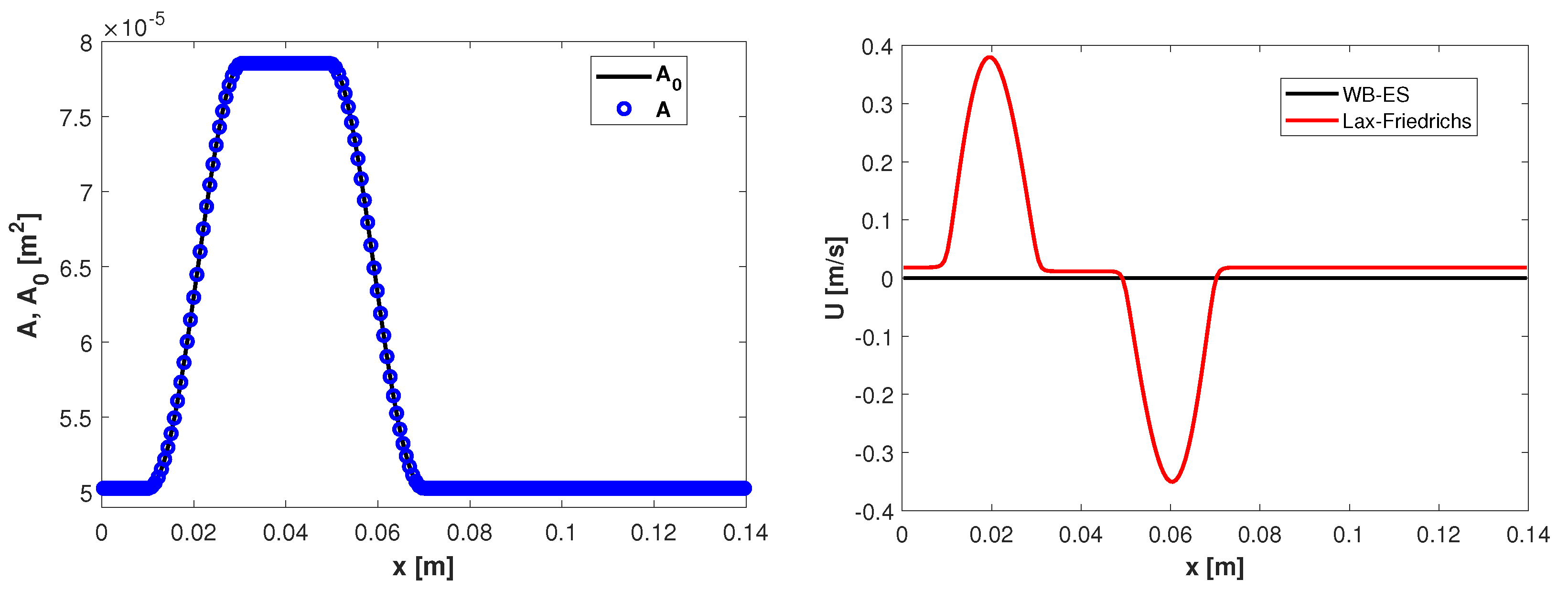
Figure 5. In
Figure 5 (left) can be observed that the area remains the same as the area at rest as expected. In
Figure 5 (right) we compare the velocity obtained by using the well-balanced and entropy stable scheme proposed in this work (hereafter referred as WB-ES) and the velocity obtained by using the Lax-Friedrichs numerical flux combined with discretization of the source term given by (
21). Notice that the WB-ES scheme preserves the steady-state exactly while Lax-Friedrichs produces unacceptable spurious oscillations. This kind of anomalies was also reported before in reference [
5].
3.1.3. Ejemplo 3
This example (see [
13]) corresponds to the case of a dead man with stenosis. Stenosis occurs when the artery narrows and it leads to reduced blood flow from the heart to the rest of the body. The cross-sectional area at rest is
, where
with
,
, an artery of length
,
,
,
,
. The initial conditions are
where
.
Numerical solutions are computed at
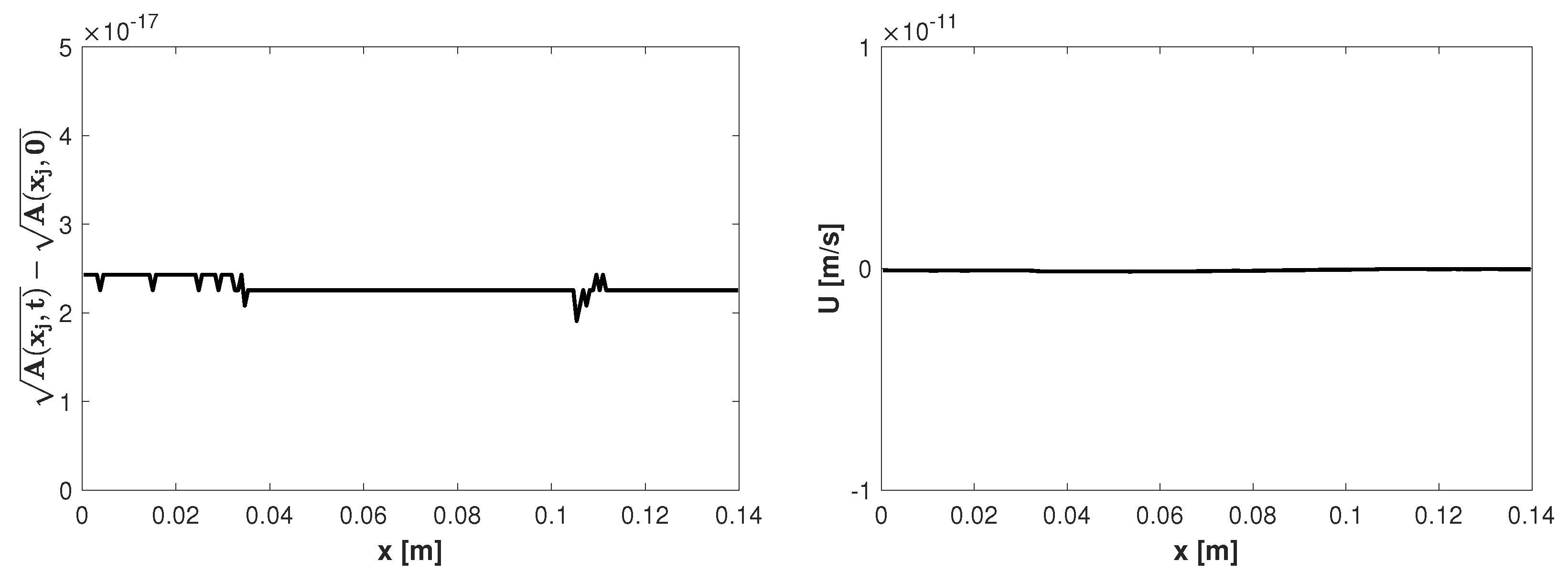
s. As observed in
Figure 6 the proposed scheme preserves the steady-state (
12) at the discrete level, i.e., the quantity
remains constant and the velocity is null.
4. Conclusions
We present a numerical scheme to approximate the solutions of a blood flow model in arteries. It was shown analytically that the scheme is entropy stable and preserves the steady state solutions. These properties were also tested numerically with some standard examples. Although higher order schemes can be found in the literature related to the numerical approximation of blood flows, the value of the second order discretization of the source term proposed in this work lies in the fact that using linear combinations of them combined with high-order entropy stable fluxes it is possible to construct arbitrarily high order entropy stable schemes that preserve the steady states solutions.
Author Contributions
Conceptualization, S.V., C.V. and J.B.; Formal Analysis, C.V., Investigation, S.V. and C.V; Software, Validation & Supervision, C.V. and J.B.; Writing-original draft, C.V.; Writing-Review & Editing, S.V. and C.V. All authors have read and agreed to the published version of the manuscript.
Conflicts of Interest
The authors declare no conflict of interest.
References
- Sherwin, S. J.; Franke, V.; Peiró, J.; Parker, K. One-dimensional modelling of a vascular network in space–time variables. J. Eng. Math. 2003, 47(3), 217–250. [Google Scholar] [CrossRef]
- Formaggia, L.; Nobile, F.; Quarteroni, A.; Veneziani, A. Multiscale modelling of the circulatory system: a preliminar analysis. Comput. Vis. Sci. 1999, 2, 75–83. [Google Scholar] [CrossRef]
- Dafermos, C. Hyperbolic conservation laws in continuum physics; Springer: Berlin, 2000. [Google Scholar]
- Guigo, A. R.; Delestre, O.; Fullana, J.M.; Lagrée, P.Y. Low-Shapiro hydrostatic reconstruction tecnique for blood flow simulation in large arteries with varying geometrical and mechanical properties. J. Comput. Phys. 2017, 331, 108–136. [Google Scholar] [CrossRef]
- Delestre, O.; Lagrée, P. Y. A ’well-balanced’ finite volume scheme for blood flow simulation. Int. J. Numer. Methods Fluids. 2013, 72, 177–205. [Google Scholar] [CrossRef]
- Tadmor, E. The numerical viscosity of entropy stable schemes for systems of conservation laws, I. Math. Comput. 1987, 49, 91–103. [Google Scholar] [CrossRef]
- Fjordholm, U.S.; Mishra, S.; Tadmor, E. Arbitrary high-order essentially non-oscillatory entropy stable schemes for systems of conservation laws. SIAM J. Numer. Anal. 2012, 50, 544–573. [Google Scholar] [CrossRef]
- Bürger, R.; Valbuena, S.; Vega, C. A well-balanced and entropy stable scheme for a reduced blood flow model. Numer. Meth. Part Differ. Equ. 2023, 39(3), 2491–2509. [Google Scholar] [CrossRef]
- Fjordholm, U.S.; Mishra, S.; Tadmor, E. ENO reconstruction and ENO interpolation are stable. Foundations of Computational Mathemathics. 2013, 13, 139–159. [Google Scholar] [CrossRef]
- Fjordholm, U.S.; Mishra, S.; Tadmor, E. Well-balanced and energy stable schemes for the shallow water equations with discontinuous topography. J. Comput. Phys. 2011, 230, 5587–5609. [Google Scholar] [CrossRef]
- Wu, K.; Shu, C.W. Entropy Symmetrization and High-Order Accurate Entropy Stable Numerical Schemes for Relativistic MHD Equations. SIAM J. Sci. Comput. 2020, 42(4), A2230–A2261. [Google Scholar] [CrossRef]
- Guitti, B.; Berton, C.; Hoang, M.; Toro, E. A fully well-balanced scheme for the 1D blood flow equations with friction source term. J. Comput. Phys. 2020, 421, 1–33. [Google Scholar] [CrossRef]
- Britton, J.; Xing, Y. Well-balanced discontinuous Galerkin methods for the one-dimensional blood flow through arteries model with man-at-eternal-rest and living-man equilibria. Computers & Fluids. 2020, 203, 1–32. [Google Scholar] [CrossRef]
|
Disclaimer/Publisher’s Note: The statements, opinions and data contained in all publications are solely those of the individual author(s) and contributor(s) and not of MDPI and/or the editor(s). MDPI and/or the editor(s) disclaim responsibility for any injury to people or property resulting from any ideas, methods, instructions or products referred to in the content. |
© 2023 by the authors. Licensee MDPI, Basel, Switzerland. This article is an open access article distributed under the terms and conditions of the Creative Commons Attribution (CC BY) license (http://creativecommons.org/licenses/by/4.0/).
