1. Introduction
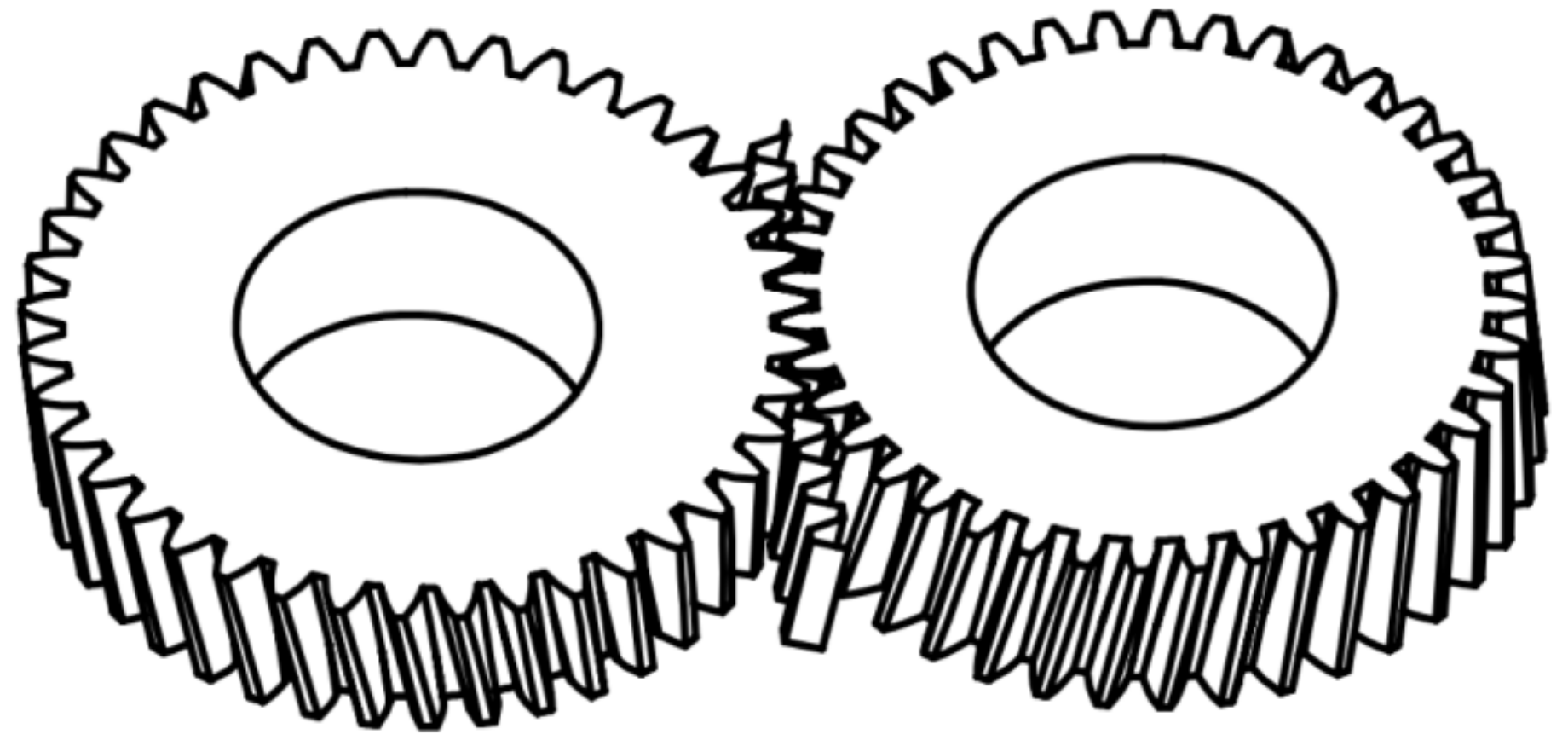
Ships, being the primary mode of water transportation, play a vital role in protecting maritime safety, marine development and exploitation, deep sea exploration, and other activities. Smart ships place a great value on power transmission stability. Traditional gears are easily disturbed by external interference in the complex marine environment, which affects the normal meshing of gear pairs and can lead to gear failure in severe cases. Whether the gear system can operate reliably becomes a bottleneck restricting the further development of smart ships. A.S. Beam proposed the concept of bevoloid gear in 1954 [
1]. The linear variation of the addendum modification factor along the tooth width direction is a feature of this gear. Furthermore, the bevoloid gear can meet a higher transmission ratio, which helps to minimize transmission system volume and make the structure more compact. It also has good adaptation to complex operating conditions and can reduce system vibration, which has a positive influence on transmission system life [
2,
3]. Bevoloid gears' time-varying meshing stiffness is an inherent property that is exclusively connected to its design parameters and exhibits periodic variations. Stiffness excitation of the gear system is caused by this characteristic during transmission, which causes dynamic excitation forces in the gear system and can affect the dynamic characteristics of the gear system such as noise and vibration directly, gives a strong nonlinearity to the dynamic equations. The analytical study of time-varying meshing stiffness of bevoloid gears helps the analysis of ship kinematic and dynamic properties, which is critical for ship navigation and control, so, there is a high demand for research in this field.
In terms of the computation of relevant design parameters of bevoloid gear, Li et al [
4] provided the entire design process of bevoloid gear as well as the procedure of calculating two lateral faces parameters. Ni et al [
5] not only completed the geometric design of bevoloid gear based on meshing theory but also investigated bevoloid gear meshing properties. K. Mitome [
6] defined the ideal gear from bevoloid gear roll-cutting processing and generated mathematical formulas for bevoloid gear tooth profiles from it. Yu et al [
7] developed mathematical formulas for the tooth profile of parallel-axis bevoloid gear pairs, derived the mathematical expressions of tooth profile and mesh line equation for parallel-axis bevoloid gear pairs, and estimated the tooth profile error and tooth orientation error based on the basic principle of gear meshing. In the research on the processing method of bevoloid gear, Wu et al [
8] proposed using the same gear shaper to generate the inner and outer bevoloid gear that mesh with each other. Wen et al [
9] investigated the grinding and modification method of bevoloid gears, they designed a gear grinding machine with a specially modified large-plane grinding wheel and optimized the modification of the involute bevoloid gears. Ni et al [
10] suggested a method for machining route of bevoloid gears with nonlinear displacement based on the traditional linear roller machining. Cao et al [
11] provided an adaptive design model, from which a mechanism to determine the installation location and grinding kinematics was devised.
ISO defines the meshing stiffness of gears as the amount of the normal load required to act on the meshing line during the meshing of gear teeth with a deflection of 1 μm over the tooth width. For the meshing stiffness of straight cylindrical gears, the stiffness calculation of three-dimensional gears is generally reduced to a two-dimensional planar problem, there are three main methods: the mechanics of materials method, the mathematical elastodynamics method, and the finite element method. The existing research uses the Ishikawa formula and the Weber energy method to study stiffness based on the material mechanics method. With the advancement of computers, it is easier to solve the meshing stiffness of gears using the finite element technique compared with others, and optimization and enhancement of modeling methods have gradually increased the accuracy of the finite element approach. Compared with straight cylindrical gears, where the changing of contact line length of helical gears leads to a nonlinear force state. Smith [
12] proposed the slice theory to achieve a more precise meshing stiffness of helical gears. Finite element software is also useful for addressing the time-varying meshing stiffness of helical gears, and it is commonly used to verify the analytical results. Zhang [
13] investigated the nonlinear vibration characteristics of bevoloid gear pairs with parallel-axis internal meshing under the action of internal and external factors, as well as the effect of parametric excitation on the transmission system's nonlinear vibration characteristics. Bai et al [
14] developed an intersecting tooth pair dynamics model and a tooth contact analysis model, as well as a micro geometric correction method to improve meshing performance. Zhu et al [
15] established two methods for calculating the tooth thickness error (TTE) of straight gears using an inclined gear-inserting machine. As bevoloid gears have variable-section along the axial and radial directions, the meshing stiffness calculation for bevoloid gear should account for elastic deformation, so previous methods for calculating elastic deformation must be imverified. Wu et al [
16] suggested an improvement to the elastic deformation formula for estimating cylindrical gear meshing stiffness. Song et al [
17] developed a method for determining the meshing stiffness of parallel-axis straight bevoloid gear pairs based on the slicing approach and the energy principle. Mao et al [
18] imverified the Weber method by using the slicing concept to compute the meshing stiffness of a bevoloid gear after tooth profile modification. Yu et al [
19] suggested applying elliptical roughness contact area distribution function to point contact of curve and developed a fractal contact mechanics model for elliptical roughness surfaces. Li [
20] calculated the meshing stiffness of intersecting axis bevoloid gear pairs using material mechanics theory and examined the impact of several parameters on the meshing stiffness of bevoloid gears. The meshing stiffness of the bevoloid gear can also be calculated using the finite element method, which requires the creation of an accurate model of the bevoloid gear as well as the calculation of the deformation and force of the gear teeth at different contact positions, and then the meshing stiffness of the bevoloid gear is solved. Bian [
21] used ANSYS to calculate the deformation of the bevoloid gear along the coordinate direction and then calculated the bevoloid gear's time-varying meshing stiffness. Furthermore, the correctness of the analytical algorithm's computation outputs can be verified using the finite element approach [
22,
23]. Wu [
24] developed an analytical and numerical approach to solve the dynamics model and differential equations of a bevoloid planetary gear system under the impact of numerous factors.
In conclusion, so much research is being conducted on the design of bevoloid gear parameters, contact characteristics, and machining procedures, which can design specific bevoloid gear pairs and complete machining operations based on the real application requirements. However, existing research on the meshing stiffness of bevoloid gears is limited, and the calculation process is only for bevoloid gears with specific parameters, with no systematic calculation method. Therefore, research on the calculation method of time-varying meshing stiffness of bevoloid gears is required.
According to the importance of research on time-varying meshing stiffness of bevoloid gears and the scarcity of research in this area, we aim to investigate the time-varying meshing stiffness of bevoloid gears on intelligent ships, to develop a theoretical system for investigating time-varying meshing stiffness of bevoloid gears, to highlight the time-varying nature of meshing stiffness, to improve the calculation method of time-varying meshing stiffness of bevoloid gears, and to standardize the calculation process. In this paper, we take involute bevoloid gears as the primary object of study, solve the tooth profile expression of involute bevoloid gears from the tooth surface shape, calculate the analytical results of time-varying meshing stiffness of bevoloid gears using the slice method and Ishikawa formula for different contact positions, and analyze the influence of different gear parameters on the time-varying meshing stiffness. The results are compared to the analytical data to ensure the accuracy of the analytical calculation approach.
2. Analysis of Meshing Contact Position of Bevoloid Gears
To calculate the time-varying meshing stiffness of the bevoloid gear, the force situation and normal deformation of the bevoloid gear during the meshing process must be obtained, and the force size and direction of the meshing point at different contact positions will differ which will affect the calculation of the meshing stiffness. To solve the time-varying meshing stiffness of bevoloid gears accurately, the accurate tooth profile expression must be calculated before obtaining the meshing contact location of the bevoloid gear pair. This section's research strategy is as follows:
(1) Starting from the normal tooth profile equation of the rack, combined with the meshing principle, based on coordinate transformation, the contact line equation of the gear and rack in the comoving coordinate system of the bevoloid gear is obtained.
(2) Changing the size of the corner, the contact line equation at different contact positions is obtained, and the bevoloid gear tooth profile is enveloped.
(3) The left and right teeth surface images of bevoloid gears are drawn as parametric equations and then to verify the correctness of the solution procedure of the bevoloid gear tooth profile equation.
(4) Letting a pair of bevoloid gears mesh with the same rack to demonstrate that the bevoloid gear is in line contact when meshing, and the contact line equation at various corners is obtained.
2.1. Derivation of the Bevoloid Gear’s Tooth-Surface Equation
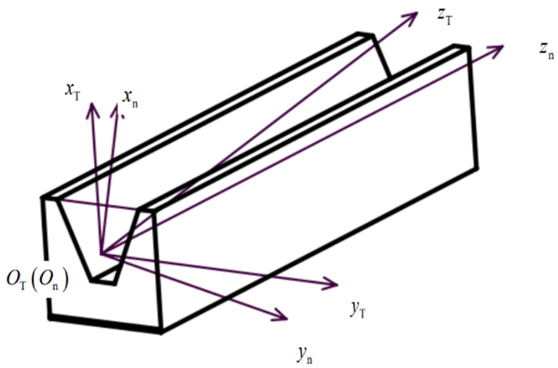
Due to the complexity of the bevoloid gear structure, it is difficult to directly calculate the tooth profile expression for bevoloid gears in each cross-section. However, the tooth profile of the gear teeth meshing with the bevoloid gear is a straight line on the normal surface, and the expression is easier to get. Therefore, the tooth profile of bevoloid gears can be calculated by solving the tooth profile equation of the rack meshing with the bevoloid gear at first, and then calculating the tooth profile of the bevoloid gear indirectly based on the meshing principle. For the left and right tooth surfaces of individual gear teeth are meshed on both sides of the tooth groove of the rack, take the intersection of the normal plane of the rack tooth groove and the index line as the Origin, and establish the rack coordinate system as is shown in
Figure 1:
The basic normal parameters of the bevoloid gear are shown in
Table 1 below:
In the figure, the coordinate system
is the end coordinate system of the rack, and the coordinate system
is the normal coordinate system of the rack. The conversion matrix
from the normal to the end coordinate system can be expressed as:
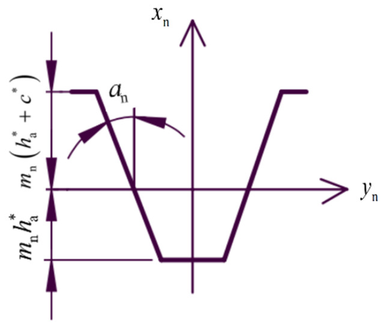
Then the tooth profile of the rack on the normal plane is two straight lines, and the shape of the rack tooth in the normal coordinate system is shown in
Figure 2:
Taking the left tooth profile of the rack as an example, the equation of the tooth profile of the rack in the normal coordinate system
can be derived based on the tooth shape of the rack in the normal section:
-indexing rounded pitch of bevoloid gears (mm).
Then the left profile of the rack can be expressed in the coordinate system of the rack end face as:
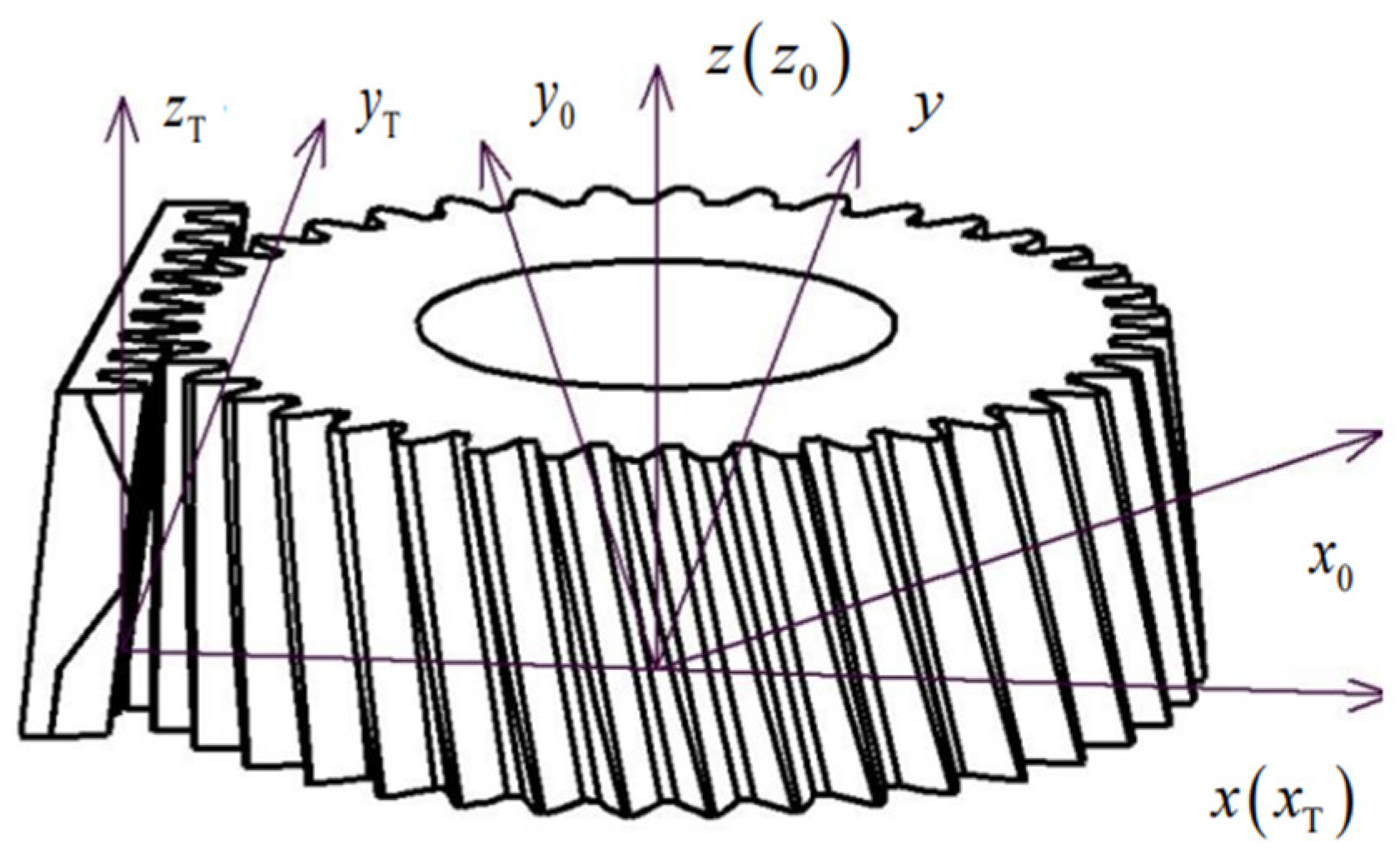
A coordinate system is established for the meshed bevoloid gear rack. As is shown in
Figure 3. Where the coordinate system
is the fixed coordinate system, the Origin is located at the center of the circle of the large end face of the bevoloid gear, and the y-axis points to the direction of the rack movement; the coordinate system
is the end face coordinate system of the rack, which is the follower coordinate system of the rack, and the distance from the fixed coordinate system in the x-direction is the gear pitch circle radius
. Coordinate system
is the follower coordinate system of the bevoloid gear, and the angle with the coordinate system
is
.
According to the coordinate system established in
Figure 3, the transformation matrix
from the coordinate system to the coordinate system is:
Then, in the coordinate system
, the equation of the left tooth surface of the rack is expressed as:
Based on the principle of gear meshing, the tangential velocity of the gear rack should be perpendicular to the normal vector of the profile of the rack to make the gear rack mesh continuously, and the coordinates of the meshing point satisfy the equation:
Since the meshing point is located on the tooth profile of the rack, the spatial equation of the mesh line of the gear and rack in the coordinate system
can be expressed as:
Therefore, it can be verified that the mesh line of the bevoloid gear and the rack is straight. Similarly, the equation of the mesh line between the right tooth profile of the bevoloid gear and the rack can be obtained. Changing the corner , the left and right tooth profiles of the bevoloid gear can be enveloped. Ensembling the left and right tooth profile equations, the mathematical expression of the equation for the single-tooth profile equation of the bevoloid gear can be obtained.
2.2. Bevoloid Gears’ Tooth-Surface Drawing
In order to verify the correctness of the derived tooth surface profile equation, the data processing software is used to obtain the point set on the tooth surface of the bevoloid gear, and after Excel processing, it is imported into the drawing software Origin to draw a three-dimensional tooth surface image, and whether the tooth profile surface equation is correct is judged from the definition of the bevoloid gear. The parameters selected during this verification are described in
Table 2:
In order to facilitate the determination of the tooth surface area of the bevoloid gear, the coordinates
、
and
on the rack normal section are used as parameters, and after the coordinate transformation, the rack profile equation in the coordinate system
can be represented by the parameters
、
and
:
Based on these above, the corresponding value
is obtained:
The value obtained in the formula is brought into the parametric Equation (8), and the dataset of the right tooth surface of the bevoloid gear is obtained, and the data set of the left tooth surface is obtained by the same method for image drawing.
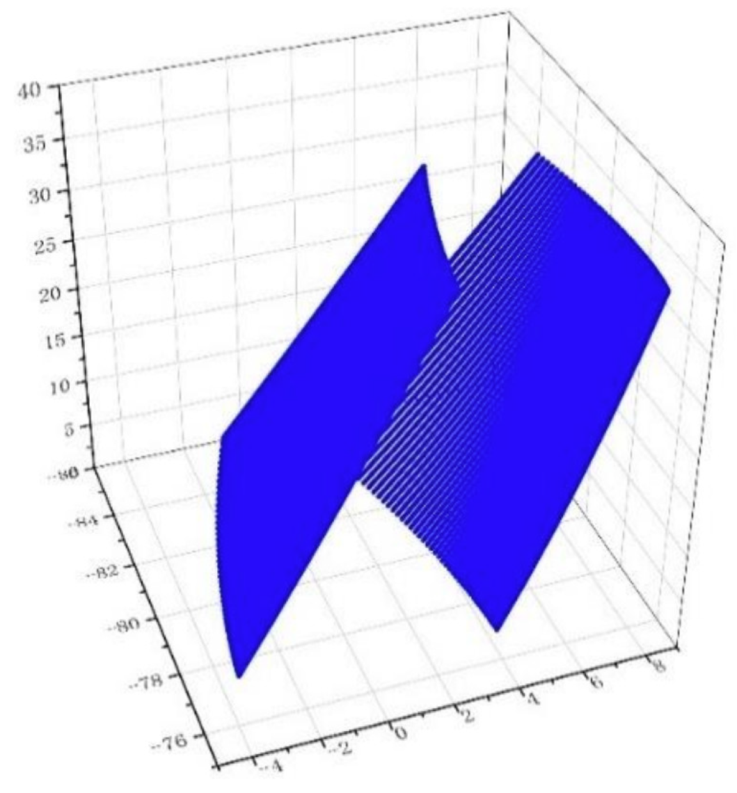
From the single-tooth surface diagram of the bevoloid gear plotted in Fig. 4, it can be seen that the bottom is the large end of the bevoloid gear. It is verified that the tooth profile of the variable bevoloid gear teeth obtained by this method is involute in each section parallel to the x-y plane, and meets the definition of bevoloid gears, so the correctness of the tooth profile surface expression can be verified. According to the tooth surface diagram of the graduated bevoloid gear, it can be seen that the shape of the left and right tooth surfaces of the helical bevoloid gear is different. Therefore, it is necessary to calculate the deformation separately for the left and right tooth surfaces involved in meshing when calculating the stiffness.
2.3. Analysis of Parallel-Axis Meshing Contact Position of Bevoloid Gears
According to the above conclusion, the straight line obtained by the intersection of the two planes of the contact line between the left and right tooth profiles and the rack of the bevoloid gear can be obtained.
For parallel-axis meshing bevoloid gears, a pair of gears meshing with each other can be considered to be meshing with the same rack at the same time.
For a pair of bevoloid gears and racks in Fig. 5, the coordinate system as shown in
Figure 3 is established. Assuming the right gear is the active wheel with rotates counterclockwise, regard the right gear as gear 1, the left gear as gear 2, and the relevant parameters are distinguished by subscripts. When meshing, the left tooth surface of gear 1 and the right tooth surface of gear 2 mesh with each other, and the helix angle of the two is the same magnitude and the direction is opposite.
Based on a series of coordinate transformations, the meshing line equation of the right tooth surface of gear 2 and the rack is converted from the coordinate system
to the coordinate system
, which can be expressed as:
Equations (10) and (7) are the same, so the contact form of a pair of parallel-axis bevoloid gears meshing with each other is line contact, and the meshing line of the two gears is the same as the straight line is verified. At the same time, for in different values, it is also possible to solve for their real-time contact lines.
3. Analytical Solution of Time-Varying Meshing Stiffness of Bevoloid Gears
3.1. Calculation of Time-Varying Meshing Stiffness of Helical Gears
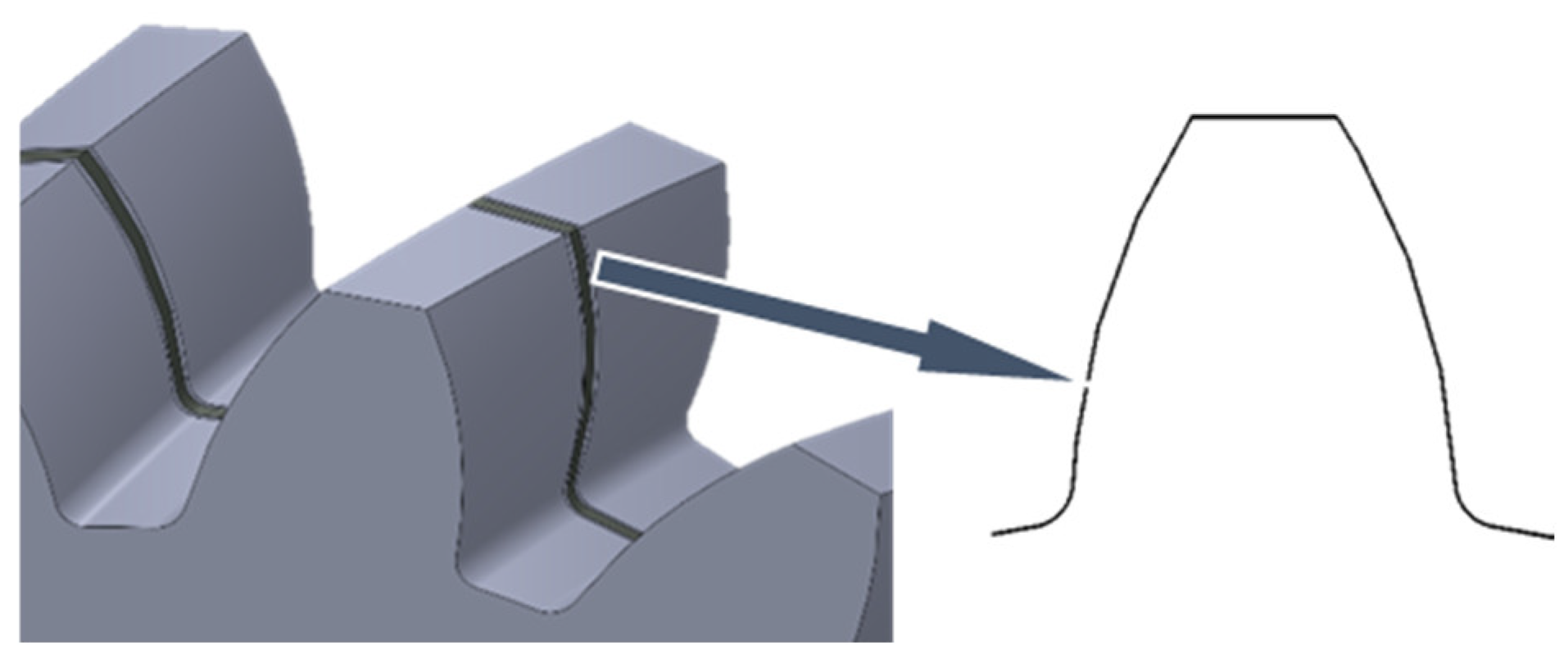
An approximate model of gear tooth slices should be established first, and then the time-varying meshing stiffness of helical gears would be calculated based on Ishikawa's formula (Ishikawa's formula is to simplify the gear teeth into a rectangular and trapezoidal combination of the cantilever beam, and use the 30° section method to determine the dangerous section of the gear, and then divide the deformation along the meshing line into four parts: the bending deformation of the trapezoidal part, the bending deformation of the rectangular part, the deformation caused by shear, and the deformation of the basic part, and obtain the deformation of the gear tooth by superposing them, and then combine the contact deformation to obtain the single-tooth meshing stiffness through the stiffness calculation formula), and the basic parameters of helical gears and their representative symbols are shown in
Table 3.
According to the idea of the slice method, one tooth of the helical gear is equally divided into N slices along the tooth width direction, as shown in
Figure 6:
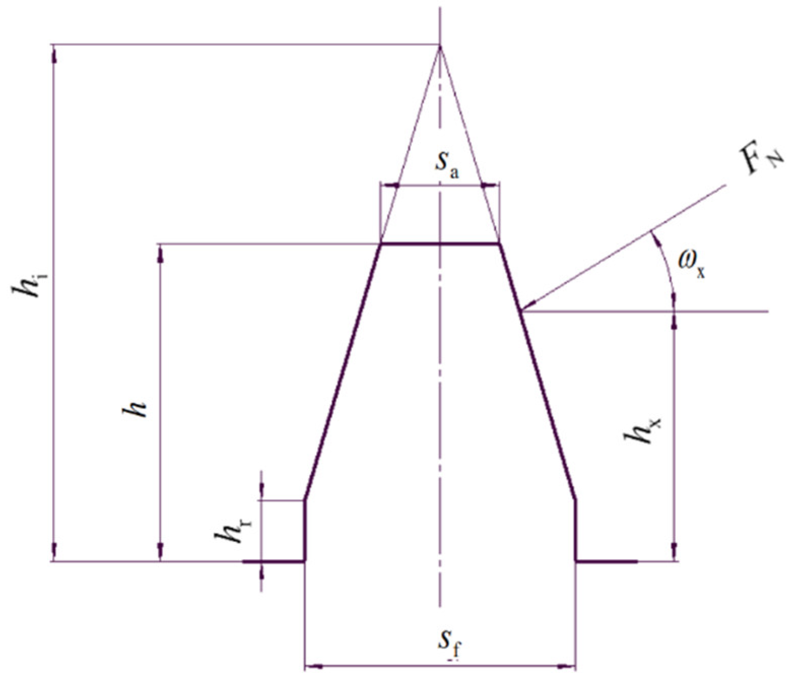
Considering the gear tooth as a cantilever beam (The displacement and rotation angle at the tooth root position are always 0 during the meshing process). Simplifying each gear tooth slice as a combination of a rectangle and an isosceles trapezoid, as is shown in
Figure 7, based on the above, calculating the deformation of a single tooth translates into calculating the deformation of this approximation.
Calculation of each parameter:
The tooth thickness of the end faces tooth apex circle of the gear tooth slice:
-the radius of the end face tooth top circle of the helical gear.
-the end face modulus;
-the end face tooth top height coefficient;
-the end face displacement coefficient of the helical gear.
-the pressure angle of the end face indexing circle of the helical gear.
-the pressure angle of the top circle of the end face of the helical gear.
-base radius of the end face of the helical gear.
-radius of effective root circle of the end face.
-the tooth thickness of the end face tooth root circle of the gear tooth slice:
- the height of approximate rectangular:
-effective root circle pressure angle of helical gear end face.
-radius of end face root circle of helical gear:
-end face top clearance coefficient of helical gear.
Full tooth height of the tooth slice:
Height of the intersection of the two waist extensions of the trapezoid:
For a pair of gears involved in meshing, let subscript 1 denote the active wheel and subscript 2 denote the driven wheel. Let the angle of rotation
of the nth tooth slice just entering the mesh be 0, then when the tooth slice of the wheel is rotated by an angle
, the radius at the position of the mesh point:
-pressure angle of the gear tooth slice entering the contact position.
-radius of entering the contact position.
Radius at the contact position of the driven wheel:
-the meshing angle at the active wheel contact position.
The angle between the direction of force and the horizontal axis:
Height of the force position:
The values of and for the active wheel and driven wheel: takes , and , respectively.
According to the Ishikawa formula, the bending deformation of the trapezoid:
E-modulus of elasticity of the gear.
The bending deformation of the rectangle:
-poisson's ratio of the gear tooth section.
Deformation of the substrate:
The total deformation of the n-th gear tooth slice:
The total deformation of the active and driven wheel tooth slices is calculated, and the contact deformation of the two slices is obtained according to the Hertz formula:
The total deformation of the two corresponding gear slices in the process of meshing:
The stiffness of the gear tooth slices:
Let the angle of rotation of the gear when the first tooth slice starts to participate in the meshing process.
The rotation angle of the n-th gear segment:
-radius of the indexing circle of the end face of the helical gear.
The angle of rotation of the gear when a single tooth slice is always meshd in a meshing cycle:
-end overlap of helical gears:
-thickness of the end indexing circle of the helical gear.
The range of angles in which the nth tooth slice is involved in the mesh:
Total stiffness of a single tooth mesh:
-number of gear slices involved in simultaneous meshing.
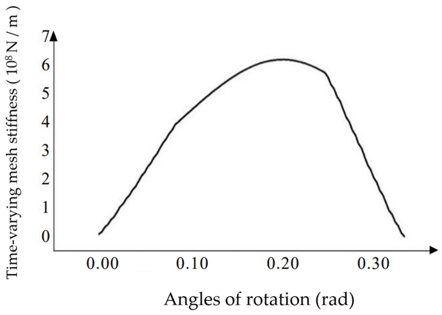
The helical gear parameters in
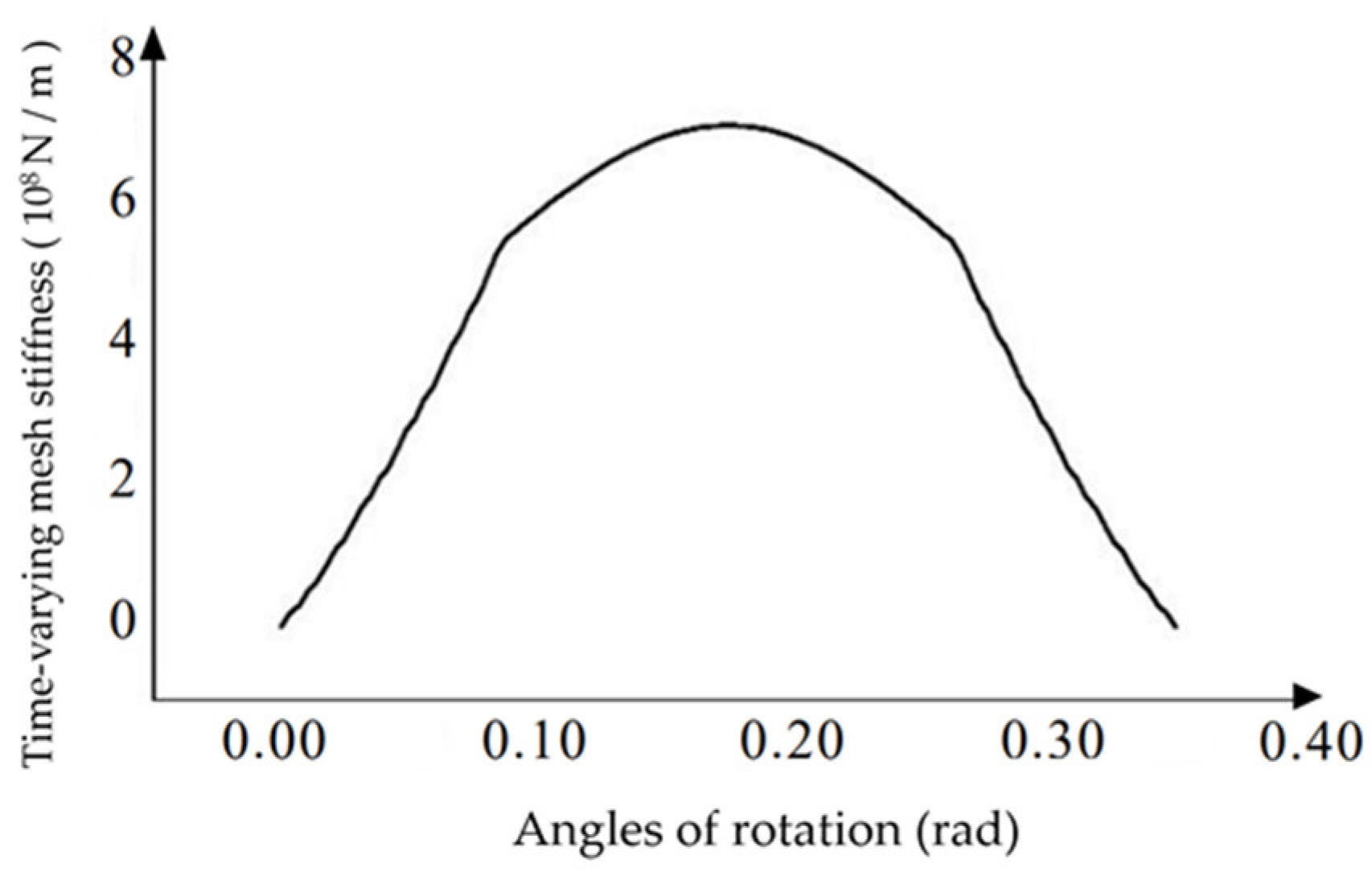
Table 4 are used to calculate the single-tooth stiffness at different corners, and the calculated data is imported into Origin to plot the single-tooth time-varying meshing stiffness image of the helical gear as shown in
Figure 8.
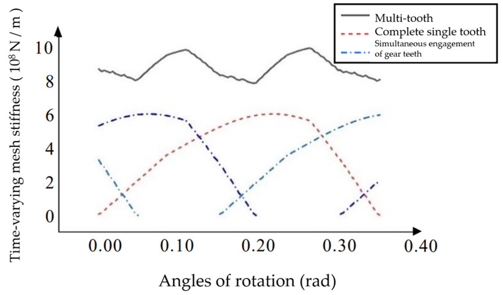
The multi-tooth meshing stiffness of the helical gear can be obtained by adding the meshing stiffnesses of multiple gear teeth. As is shown in
Figure 9. It can be seen from
Figure 9 that the helical gear is divided into a two-tooth meshing zone and a three-tooth meshing zone during the meshing process.
3.2. Calculation of Time-Varying Meshing Stiffness of Straight Bevoloid Gears
The time-varying meshing stiffness of straight bevoloid gears is calculated by using the Ishikawa formula and the slice method, while the helix angle is 0. The end face modulus of the straight tooth bevoloid gear is fixed, but
,
,
will change:
The displacement coefficient of the bevoloid gear at different tooth widths positions is different, and for the bevoloid gear with the intermediate end face displacement coefficient of 0, the displacement coefficient of the n-th tooth slice satisfies:
The meshing stiffness of individual gear slices can be calculated by substituting the parameters of straight bevoloid gears into the formula above. Due to the different displacement coefficients of the gear slices at different tooth widths of the straight bevoloid gear, the coincidence degree is different for each group of gear tooth slices when meshing.
After calculation, the slices at the middle-end face have the largest coincidence degree during meshing and are involved in the longest meshing process during the gear rotation process.
The stiffnesses of the gear tooth slices involved in simultaneous meshing were superimposed to obtain the total stiffness of single tooth meshing. The single-tooth stiffness at different corners is calculated by using the variable bevoloid gear parameters except for the helix angle in
Table 2, and the calculated data is imported into the Origin, and the image of Single tooth time-varying meshing stiffness of bevoloid gears at different angles of rotation is shown in
Figure 10. And the image of Single tooth time-varying meshing stiffness of bevoloid gears at different angles of rotation is shown in
Figure 11.
3.3. Calculation of Time-Varying Meshing Stiffness of Helical Bevoloid Gears
For helical bevoloid gears, the end-indexing circle pressure angles on the left and right tooth profiles are different and can be expressed as:
The size of the corresponding base circle on the left and right tooth surfaces:
The tooth shape obtained by the slicing method is asymmetric, and the meshing deformation cannot be calculated directly by Ishikawa's simplification, so the tooth cross-section of the helical bevoloid gear is simplified into a combination of an oblique trapezoid and a rectangle, as is shown in
Figure 12:
From the calculation of the basic gear parameters, it can be found that the top circular pressure angle and the root circular pressure angle on the left and right tooth surfaces are also different, so they should be calculated separately from the left and right tooth surfaces in the calculation of ,,. For the approximate tooth shape is asymmetrical, its deformation needs to be recalculated using the formula of material mechanics.
The parameters to be changed are calculated as follows:
Observe from the large end of the active wheel, and let the active wheel rotate counterclockwise, the left tooth surface of the active wheel is in contact with the right tooth surface of the driven wheel under force, then the pressure angle at the position where the slices of the wheel teeth start to mesh:
The radius equation at the contact position corresponding to different angles:
The radius at the contact position of the driven wheel:
The distance between the line of symmetry of the tooth thickness at the top of the tooth and
:
According to the energy method, the bending deformation can be expressed as:
-the moment of inertia of the approximate toothed section.
Moment of inertia of rectangular section:
Moment of inertia of trapezoidal section:
Similarly, the energy method can be used to calculate the shear deformation of the approximate tooth shape:
-The coefficients corresponding to the cross-sectional shape.
-shear modulus of the material.
-Cross-sectional area of different sections.
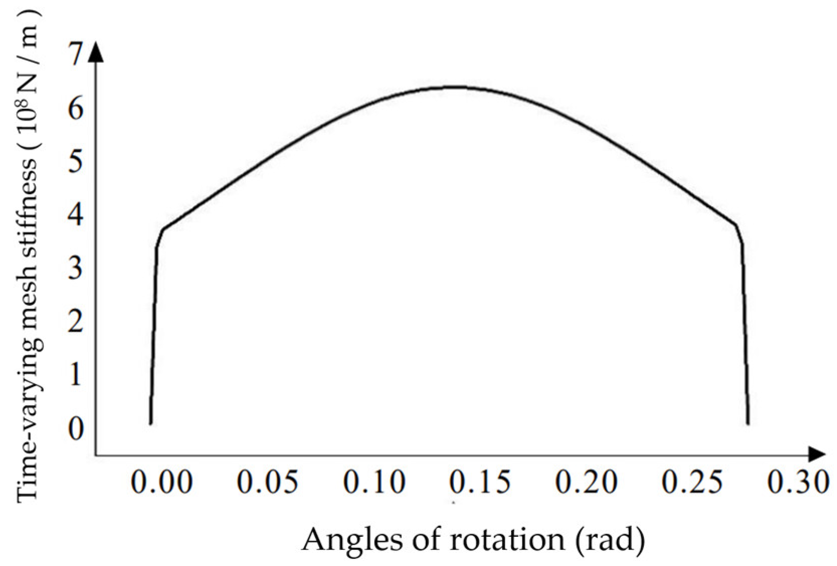
The substrate deformation and contact deformation can be calculated by Ishikawa's formula. For an intermeshing pair of tooth slices, the calculated deformations are summed to obtain the total deformation of the tooth slices, and then the stiffness of the tooth slices is calculated by dividing the total deformation with the normal force. As is shown in
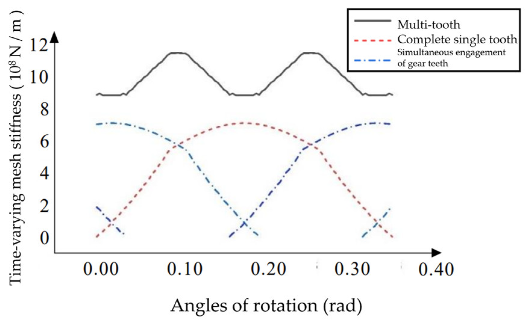
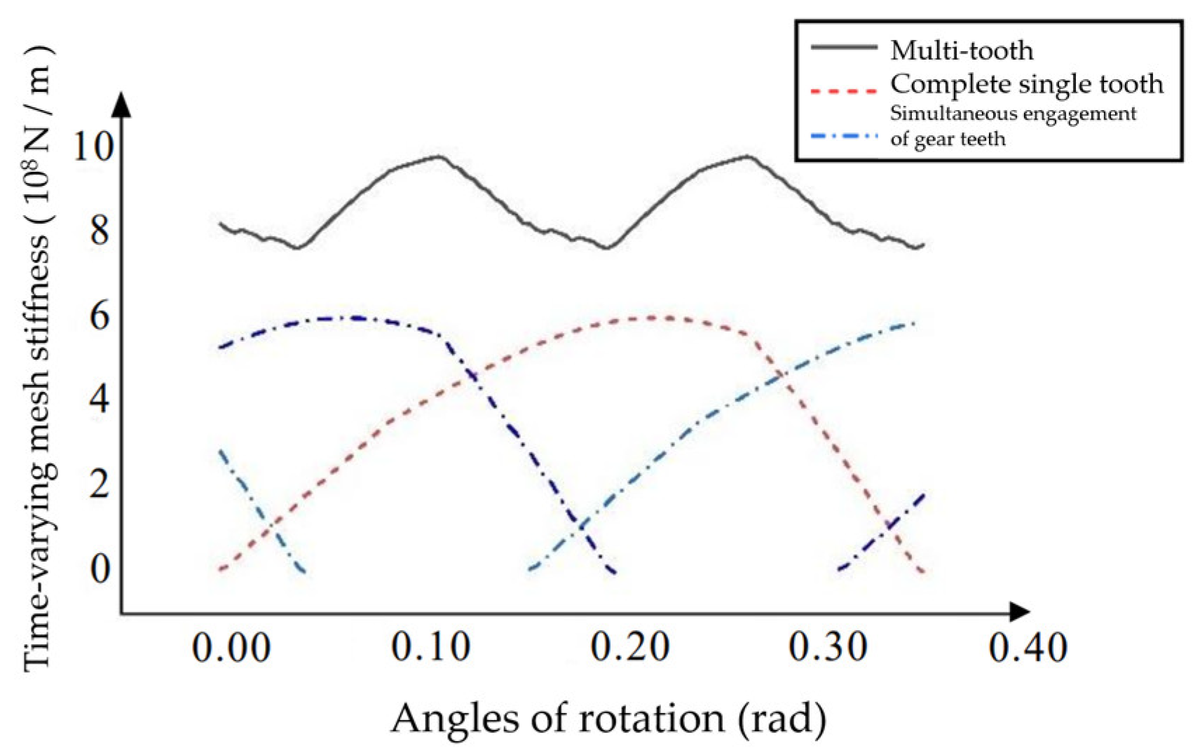
Figure 13, the image of the single tooth meshing stiffness in forward rotation is obtained by superposition. And the image of the multi-tooth meshing stiffness in forward rotation is shown in
Figure 14:
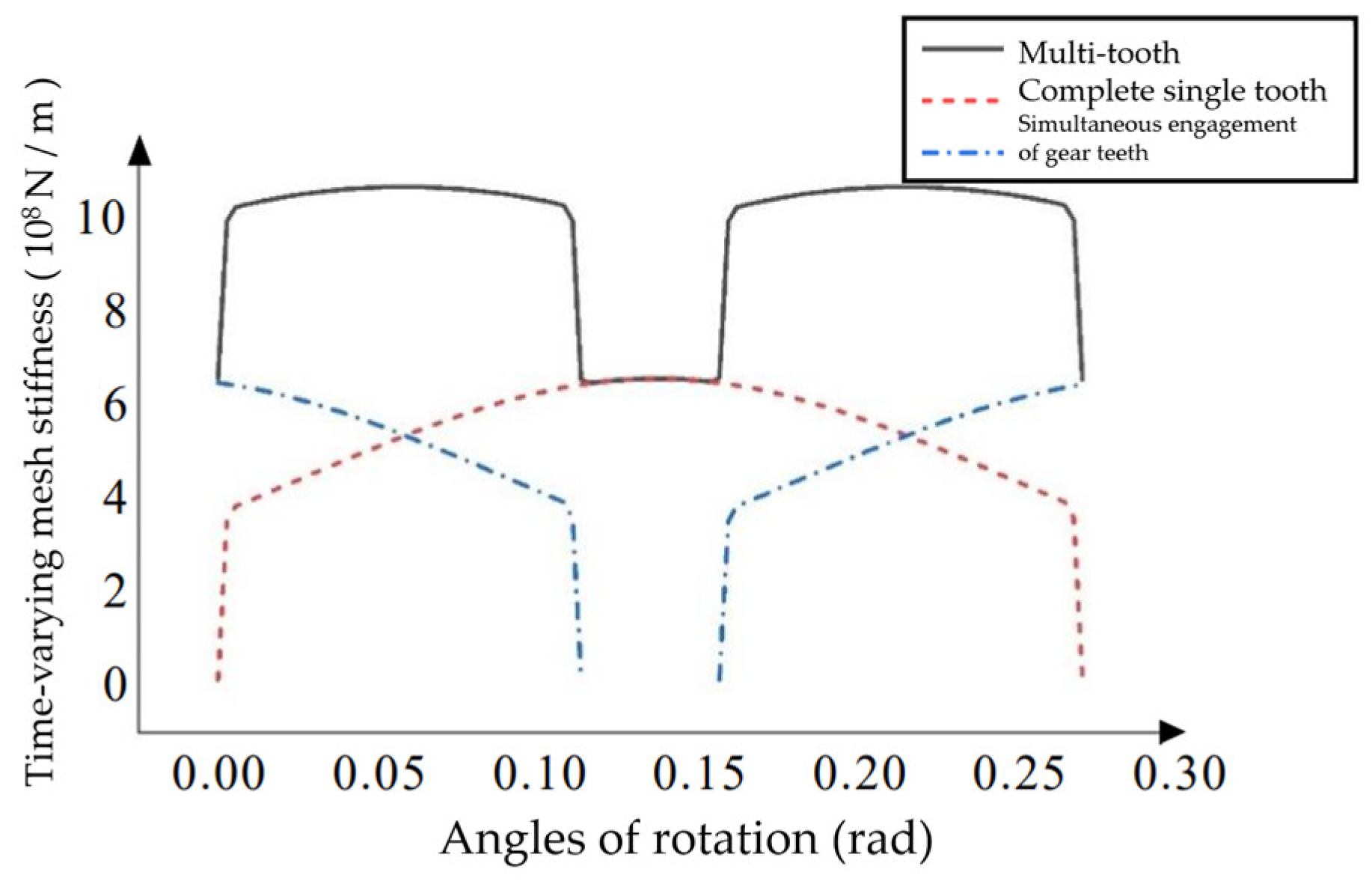
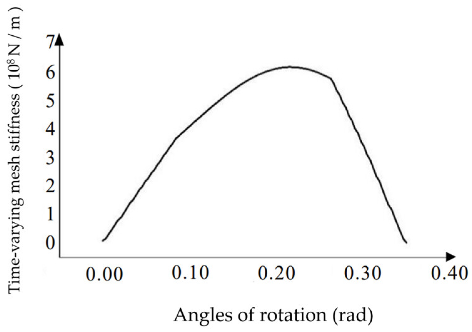
Similarly, the image of the single tooth and the multi-tooth meshing stiffness in reverse rotation is shown in
Figure 15 and
Figure 16.
After comparison, the change of single tooth meshing stiffness is the same for both bevoloid gears in forward and reverse rotation, but the total overlap is relatively small in reverse rotation, resulting in the difference of variable meshing stiffness image in multi-tooth.
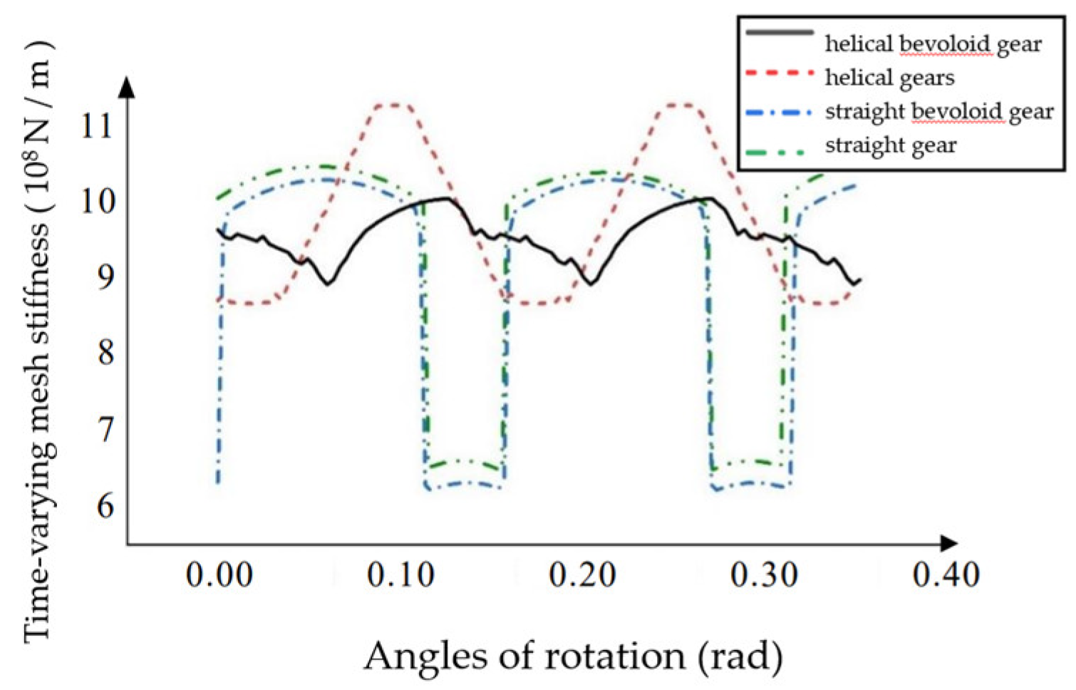
The differences in the multi-tooth time-varying meshing stiffness of helical bevoloid gears, helical gears, straight bevoloid gears and straight gears were compared.
After comparison, it was found that the multi-tooth time-varying meshing stiffness of bevoloid straight gears is smoother than that of straight gears, but the improvement is not large, and the stiffness image is similar to that of straight gears. Helical and helical bevoloid gears change stiffly more smoothly, meshing is more stable, and provides greater stiffness when meshing. Helical bevoloid gears have a smaller stiffness variation range and are more stable during transmission under the premise of providing stiffness similar to helical gear size.
3.4. Analysis of Stiffness Influencing Factors
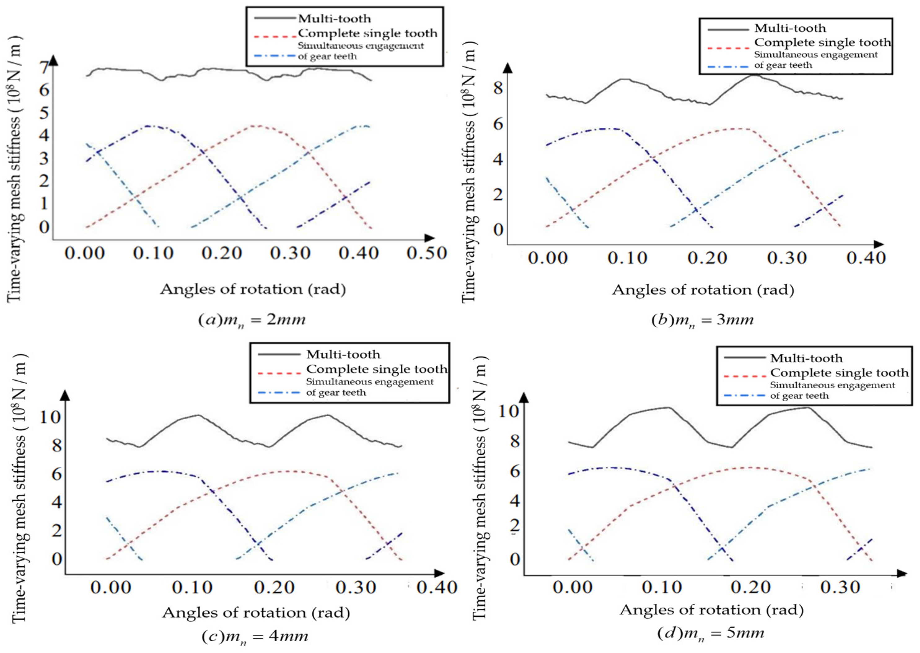
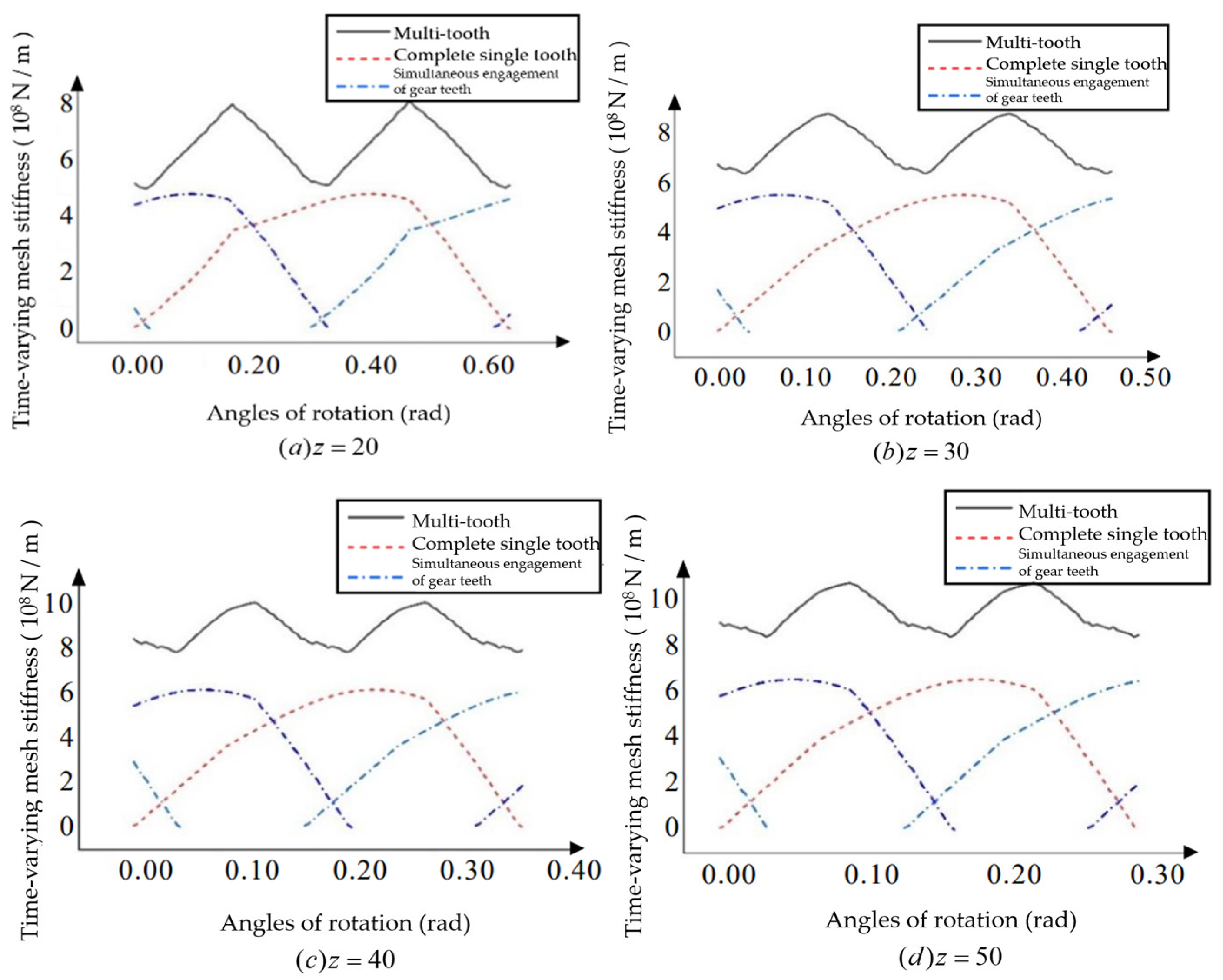
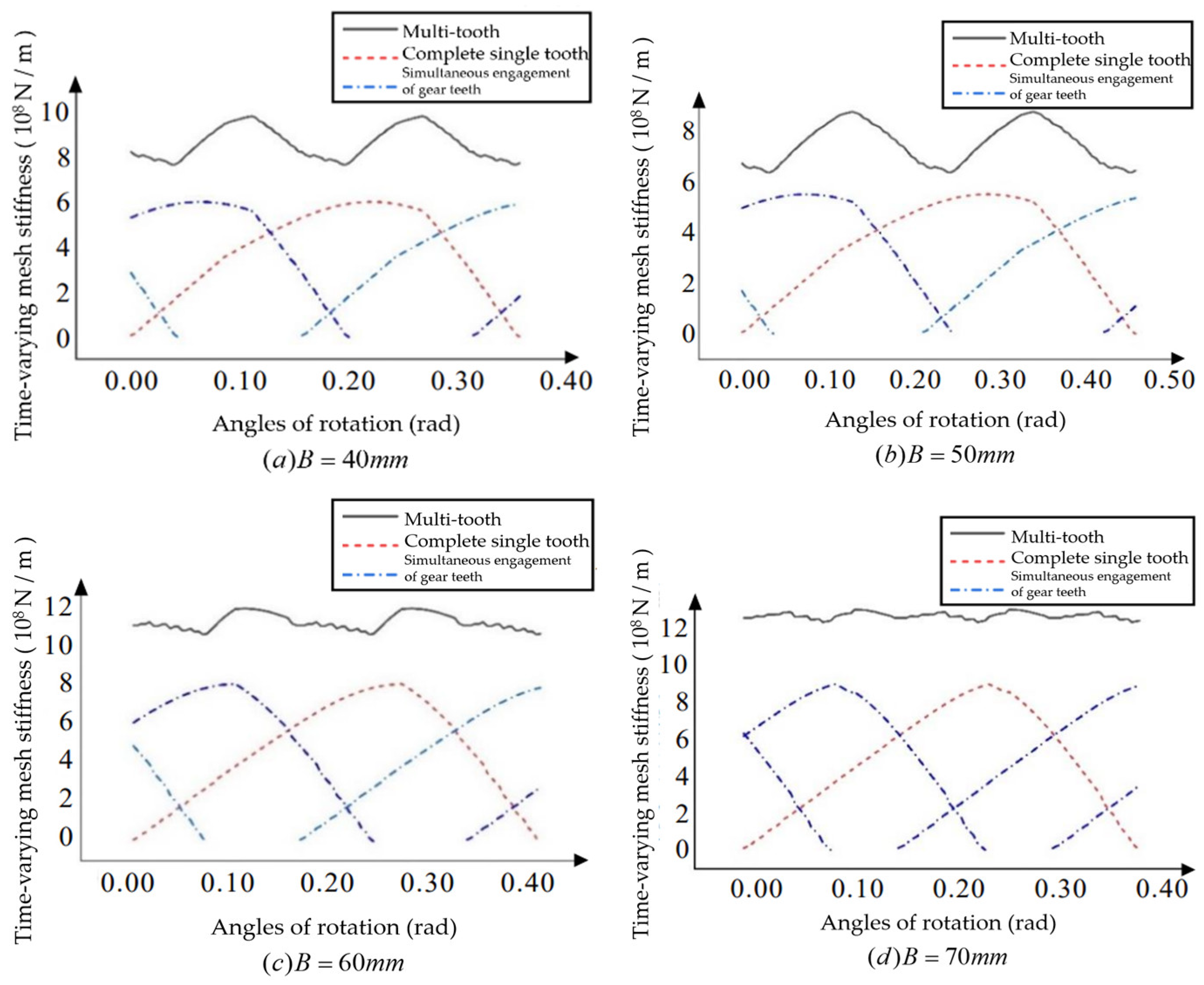
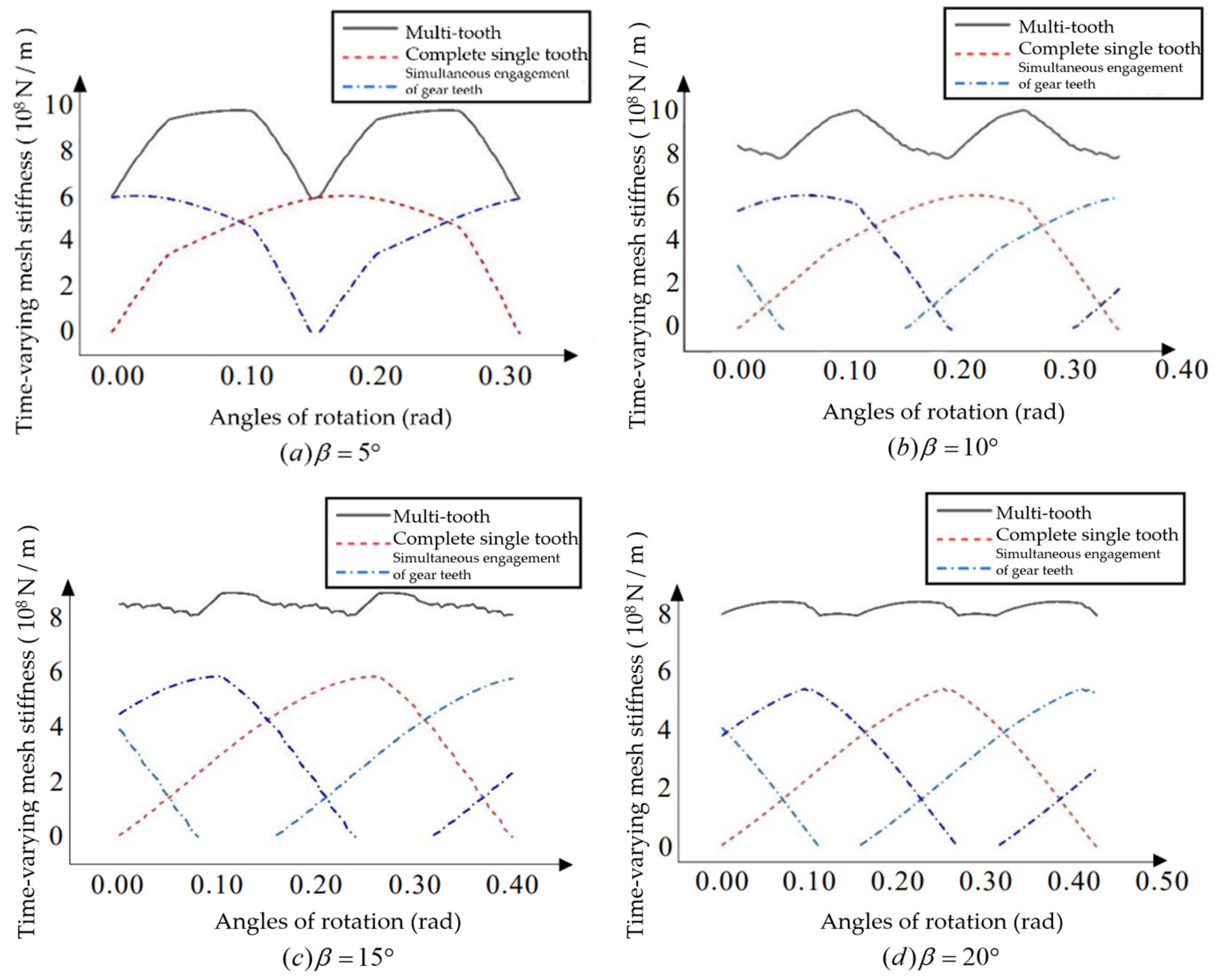
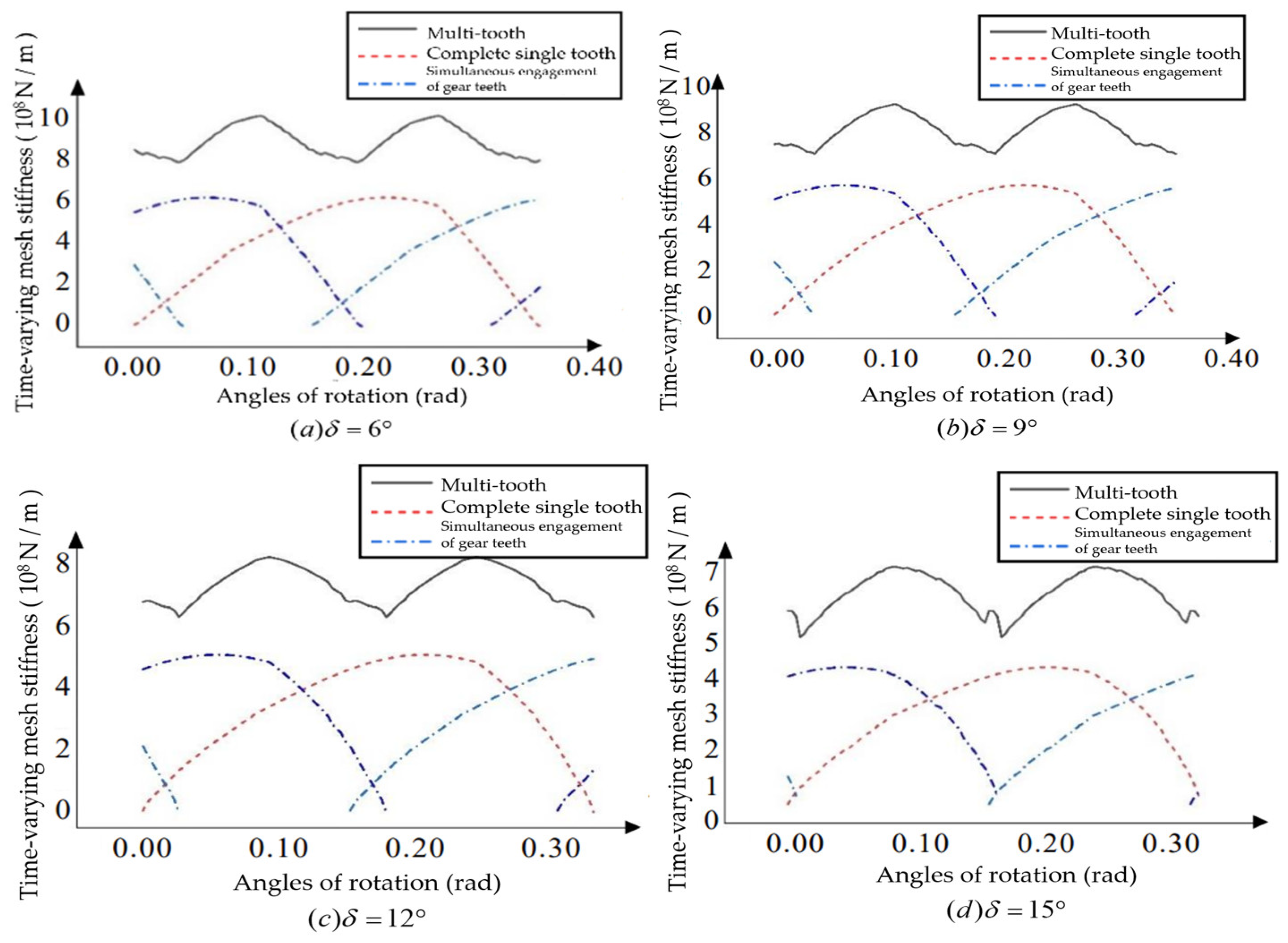
For the helical bevoloid gears in forward rotation condition, the basic parameters are changed, and the influence of the Module, Number of teeth, Pressure angle, Helix angle, Taper angle, and Tooth width on the multi-tooth time-varying meshing stiffness is analyzed with the average meshing stiffness and fluctuation degree as indicators.
From
Figure 18, it can be obtained that the normal modulus increases, the single tooth meshing stiffness increases and the total coincidence degrees decreases, which increases the degree of gear meshing fluctuation.
From
Figure 19, it can be obtained that the number of teeth has little effect on the degree of fluctuation.
From
Figure 20, it can be obtained that the tooth thickness increases, the single-tooth meshing stiffness and multi-tooth meshing stiffness increase, and the total coincidence degrees increases.
From
Figure 21, it can be obtained that the helix angle increases, the single-tooth meshing stiffness and multi-tooth meshing stiffness decrease, and the total coincidence degrees increases.
From
Figure 22, it can be obtained that the taper angle increases, the single-tooth meshing stiffness and multi-tooth meshing stiffness decrease, and the total coincidence degrees decreases.
4. Numerical Solution of Time-Varying Meshing Stiffness
In order to verify the correctness and accuracy of the analytical method, the three-dimensional models of helical gears and helical bevoloid gears were established and imported into ABAQUS for finite element simulation, the contact force and contact displacement were read, and the time-varying meshing stiffness of single tooth and multi-tooth were calculated respectively.
4.1. Finite Element Contact Analysis of Helical Gears
According to the definition of helical gear, the parameters such as the three-dimensional diagram of the helical gear in
Table 4 are drawn, and after assembly, it is imported into ABAQUS for analysis. Firstly, set the material of both gears as
steel, the density is
/mm, the modulus of elasticity is 208,000 MPa, and Poisson's ratio is set to 0.27. Next, the inner surface of the gear is coupled about the gear center point, and the contact situation is set for both gears: the friction coefficient is set to 0.1 in the normal behavior, and the tangential behavior is set to " hard contact" in the tangential behavior. Finally, the boundary conditions and loads of the two helical gears are set, and all degrees of freedom except axial rotation is restricted for the active wheel, and all degrees of freedom are fixed for the driven wheel, and a torque of
is applied to the active wheel, and the active and driven wheels are divided into two blocks, with a circular column in the middle part, and the approximate global size of the layout points is set to 5, and the approximate global size of the layout points at the tooth positions is 0.8.
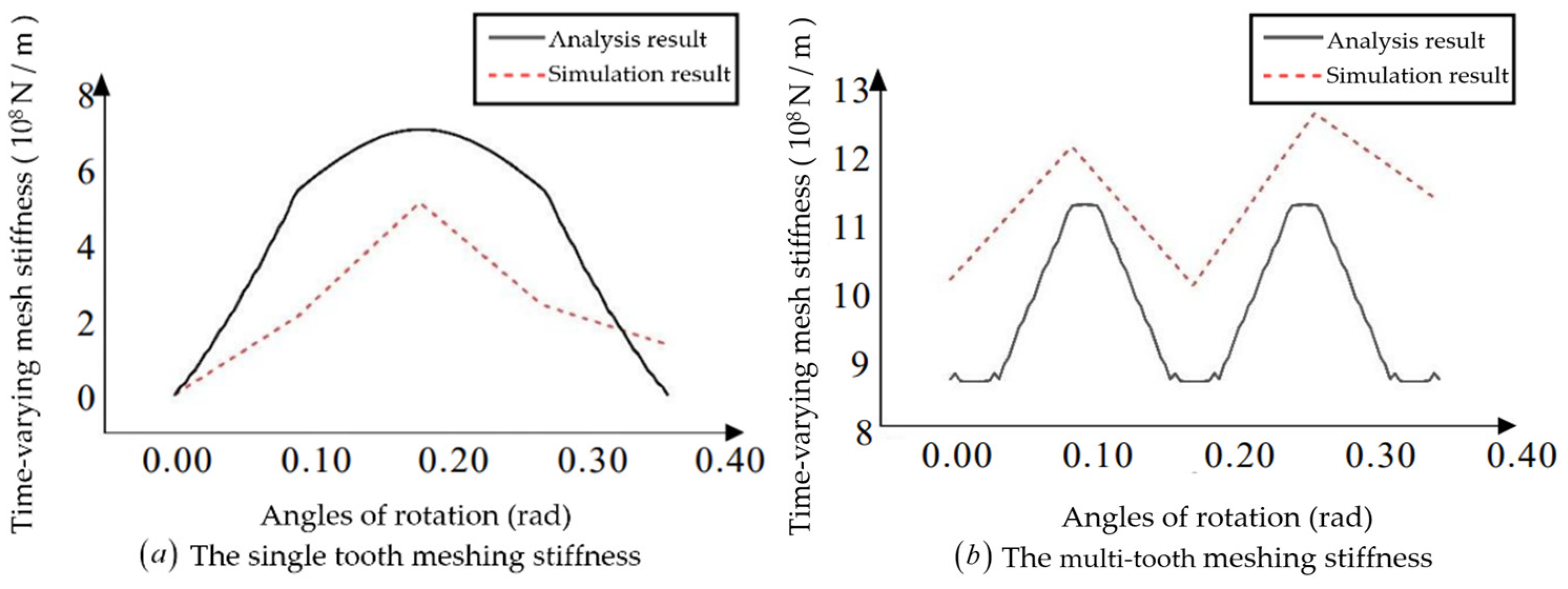
The contact displacement and contact force at the contact position are read by setting different rotation angles for the gear, and the single tooth meshing stiffness obtained from the finite element simulation is plotted simultaneously with the multi-tooth meshing stiffness and the analytical calculation results, as is shown in
Figure 23:
From
Figure 23, it can be seen that the trend of the single tooth meshing stiffness of the finite element calculation is consistent with the analytical calculation, but the single tooth meshing stiffness size is smaller than the analytical calculation. The possible reason for the above error is that the finite element calculation has a large span of the angle of rotation and does not take the maximum contact position of the gear tooth stiffness. The trend of the multi-tooth time-varying meshing stiffness from the finite element calculation is approximately the same as that from the analytical calculation, but the finite element calculation results are relatively larger and less volatile. Therefore, the difference between the two calculation methods for helical gears is considered to be within the acceptable range, the finite element analysis results can prove the correctness of the analytical calculation results.
4.2. Finite Element Contact Analysis of Helical Bevoloid Gears
The helical bevoloid gear is simplified by removing the intermediate base part and establishing a model with only six complete gear teeth at the contact position. The same material, force and boundary conditions are applied to the helical gear. In drawing the mesh, due to the complexity of the helical bevoloid gear, a tetrahedral shape mesh is used at the boundary position of the gear teeth, and the approximate global size of the cloth points at the gear teeth position is set to 0.8, and the approximate global size at the inner ring position is set to 5.
To obtain the time-varying meshing stiffness of the bevoloid gear, it is necessary to make a pair of bevoloid gear pairs mesh at different angles of rotation to derive the contact displacement and contact force at different angles of rotation. When the helical bevoloid gears mesh, the magnitude of the forces at both ends of the contact line is relatively small, and this part of the data can be considered to be removed when calculating the stiffness. To ensure that the sampling can be selected to the position with the largest force, a point is selected for every 6 meshes along the tooth profile direction to complete the path creation. The contact data of all the teeth involved in meshing at the same angle of rotation are extracted, and the average values of force and displacement are obtained by averaging, and then the meshing stiffness is calculated.
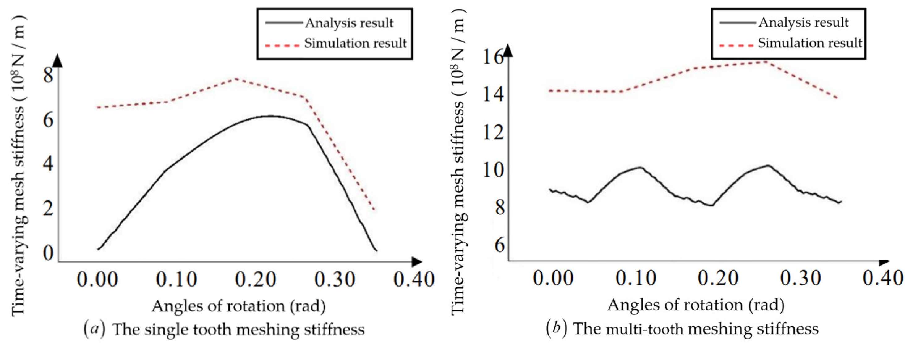
The single-tooth meshing stiffness obtained from the finite element simulation is plotted together with the multi-tooth meshing stiffness and the analytical calculation results. As is shown in
Figure 24:
After comparison, the difference between the finite element calculation results and the analytical error results was found to be large. For helical bevoloid gears, due to model complexity and insufficient modeling accuracy, there are problems in the process of importing the finite element software that resulting in large errors.
5. Conclusions
To develop the study of the dynamic performance of bevoloid gears, based on the relevant theory of slicing method and Ishikawa formula, the time-varying meshing stiffness of helical gears, straight bevoloid gears, and helical bevoloid gears is calculated, and the correctness of the calculation results is verified. Follows are the main conclusions:
1. Starting with the rack's normal coordinate system, the rack tooth shape equation in the rack end coordinate system is obtained via coordinate transformation, and the meshing line equation in the rack end coordinate system is obtained by combining with the meshing principle. The meshing line equation is then transferred into the bevoloid gear's follow-up coordinate system via coordinate transformation, and the bevoloid gear's tooth surface equation is enveloped by adjusting the gear rotation angle. The equation of the rack in the normal coordinate system is then expressed as a parameter and the parameter equation of the tooth surface of the bevoloid gear is obtained. Changing the value of parameters, the left and right tooth surface images of the bevoloid gear are drawn, which confirms the correctness of the equation derivation process. It is demonstrated that the meshing line of the parallel-axis bevoloid gear is a straight line by assuming that a pair of bevoloid gears mesh with the same rack, and the equation expression of the line in space at different moments is given.
2. Starting with the helical gear, the gear tooth slice is evenly divided in the direction of tooth width, and the stiffness of a single gear tooth slice is obtained by using the Ishikawa formula to calculate the deformation of each gear tooth slice, and then the single tooth meshing stiffness is obtained by superposition. Unfolding the helical gear's working plane, the contact of adjacent gear teeth is analyzed, and the meshing stiffness of multi-tooth is obtained by superimposing the stiffness of each distinct gear teeth at the same angle. For straight bevoloid gears, the characteristics of different coincidence degrees of meshing between different layer gear tooth slices are highlighted, and the time-varying meshing stiffness is determined. Due to the asymmetry of the end face's left and right tooth faces, the end tooth shape is approximated as a combination of a rectangle and an oblique trapezoid, and the deformation of the contact position is calculated using the energy principle, and then the meshing stiffness of the bevoloid gear is calculated. The time-varying meshing stiffness of the bevoloid gear pair is calculated separately under forward and reverse rotation, and it is discovered that the changing trend of single-tooth meshing stiffness of the two is consistent, but the total coincidence degrees during reversal is relatively small, resulting in a difference in the multi-tooth meshing stiffness image. Comparing the meshing stiffness of straight gear, helical gear, straight bevoloid gear, and helical bevoloid gear when multi-tooth meshing, it is discovered that the meshing stiffness of straight gear and straight bevoloid gear is not significantly different, whereas the average meshing stiffness of helical gear and helical bevoloid gear is larger and the degree of fluctuation is smaller. The basic parameters of the helical bevoloid gear are then altered, and the effects of Module, Number of teeth, Pressure angle, Helix angle, Taper angle, and Tooth width on the meshing stiffness of multi-tooth are investigated using the average meshing stiffness and fluctuation degree as indicators.
3. The static analysis of helical gears and helical bevoloid gears is performed using ABAQUS. Set different gear corners, read the contact displacement and contact force at the contact position, and calculate the single-tooth and multi-tooth meshing stiffnesses. The maximum stiffness is utilized as the standard for single-tooth meshing stiffness; for multi-tooth meshing stiffness, the difference between the analytical and finite element results is determined using the average stiffness and fluctuation degree. After calculation and comparison, it is determined that the difference between the results obtained by the two helical gear calculation methods is within an acceptable range, in other words, the finite element analysis results can verify the correctness of the analytical calculation results. For helical bevoloid gears, due to model complexity and insufficient modeling accuracy, there are problems in the process of importing the finite element software that resulting in large errors.
Author Contributions
Jianmin Wen conceived and designed the study, and applied for the funding which financially supported the study. Haoyu Yao conducted data extraction and performed the analyses, and wrote the article. Bindi You and Qian Yan provided their comments and suggestions during discussions and by writing, especially on the data extraction method and paper formatting.
Funding
This work is supported by the National Natural Science Foundation of China under Grant Nos. 52075116 and 52175082, and the Natural Science Foundation of Shandong Province under Grant No. ZR2021ME025.
Acknowledgments
In this section, you can acknowledge any support given which is not covered by the author contribution or funding sections. This may include administrative and technical support, or donations in kind (e.g., materials used for experiments).
Conflicts of Interest
The authors declare that they have no known competing financial interests or personal relationships that could have appeared to influence the work reported in this paper.
References
- BEAM A S. Beveloid gearing[J]. Machine Design, 1954, 26(12): 220-238.
- LI Guixian, WU Junfei, LI Huamin, et al. Design and calculation of meshing involute thickening gears in parallel shafts[J]. China Mechanical Engineering, 2000: 52-55+53.
- DU Xuesong, ZHU Caichao, SONG D, et al. Current situation and development trend of interleaved shaft helical gear transmission variable tooth thickness technology[J]. Mechanical Design, 2012, 29: 1-7.
- LI H, HAN Y, WANG ZH. Geometric principle and calculation of involute gear[M]. Beijing: China Machine Press, 1985: 245-300.
- NI G, ZHU C, SONG D, et al. Geometric design and meshing characteristics analysis of gear transmission with parallel shaft involute thickening[J]. Journal of Xi'an Jiaotong University, 2016, 50: 57-64.
- K. M. Table sliding taper hobbing of conical gear using cylindrical hob. Part 1: theoretical analysis of table sliding taper hobbing[J]. Journal of Engineering for Industry, 1981, 103(4): 446-451.
- YU GB, WEN JM, NIE JF, et al. Research on meshing theory and simulation of noninvolute beveloid gears with crossed axes[J]. Applied Mechanics and Materials, 2013, 2205: 229-232. [CrossRef]
- WU J, LI G, LI H. Study on oblique inserting process of gear pair with internal meshing and thickening[J]. Journal of Nanjing University of Aeronautics and Astronautics, 1999: 516-521.
- WEN Jianmin, LI Guixian, LI Xiao, et al. Study on non-involute thickening gear repair method[J]. Journal of Harbin Engineering University, 2003,660-663.
- NI Gaoxiang, ZHANG Zhang, LIU Siyuan et al. Analysis of contact characteristics of gear transmission with nonlinear displacement and thick interleaved shaft[J].Journal of Wuhan University of Science and Technology,2023,46(02):118-126.
- Cao, Bing,Li, Guo Long,Fortunato, Alessandro,Ni, Heng Xin. Continuous generating grinding method for bevoloid gears and analysis of grinding characteristics[J]. Advances in Manufacturing,2022. [CrossRef]
- SMITH J D. Estimation of the static load distribution factor for helical gears[J]. Proceedings of the Institution of Mechanical Engineers, Part C: Journal of Mechanical Engineering Science, 1995, 209(3): 193-199. [CrossRef]
- Zhang Hong, Research on nonlinear vibration characteristics of internal bevoloid gear transmission system[D]. Harbin Institute of Technology, 2019. [CrossRef]
- Bai Bo,Kuang Yuhua,Guo Wenchao,Mao Shimin. Influence of Misalignment on Bevoloid Gear Tooth Contact and Dynamic Characteristics in Transfer Case Transmission of AWD Vehicle[J]. Shock and Vibration,2022. [CrossRef]
- Zhu, Feihong, Song, Chaosheng,Zhu, Caichao,Du, Xuesong. Tooth Thickness Error Analysis of Straight Bevoloid Gear by Inclined Gear Shaping[J]. International Journal of Precision Engineering and Manufacturing,2022. [CrossRef]
- WU Junfei, GUO Jianzhang. Study on Determination Method of Comprehensive Stiffness Meshing of Gear Teeth with Thickened Gear[J]. Journal of Qingdao Institute of Chemical Technology (Natural Science Edition), 2002: 74-76.
- SONG C, ZHOU S, ZHU C, et al. Modeling and analysis of meshing stiffness for straight beveloid gear with parallel axes based on potential energy method[J]. Journal of Advanced Mechanical Design, Systems, and Manufacturing, 2018, 12(7): 1-14. [CrossRef]
- MAO Hancheng, FU Lin, YU Guangbin, et al. Numerical calculation of meshing stiffness of thickened gear considering gear tooth modification[J]. Computer Integrated Manufacturing Systems, 2020: 1-18.
- Yu Guangbin, Mao Hancheng, Jiang Lidong, Liu Wei, Valerii Tupolev. Fractal Contact Mechanics Model for the Rough Surface of a Bevoloid Gear with Elliptical Asperities[J]. Applied Sciences,2022,12(8). [CrossRef]
- LI Hang. Analysis of meshing characteristics and dynamic performance optimization of small helix gear transmission system[D]. Chongqing: Chongqing University, 2018: 25-34.
- Bian Yonghong. Analysis and experimental study on gear transmission performance of intersecting shaft thickening[D]. Harbin: Harbin Institute of Technology, 2015: 20-24.
- MAO H, SUN Y, XU T, et al. Numerical calculation method of meshing stiffness for the beveloid gear considering the effect of surface topography[J]. Mathematical Problems in Engineering, 2021: 1-17. [CrossRef]
- SUN R, SONG C, ZHU C, et al. Numerical study on contact force of paralleled beveloid gears using minimum potential energy theory [J]. The Journal of Strain Analysis for Engineering Design, 2021, 56(4): 249-264. [CrossRef]
- Wu Fenzhi, Study on dynamic characteristics of planetary bevoloid gear drive system at alternating temperature[D]. Harbin Institute of Technology, 2020. [CrossRef]
Figure 1.
Establishment of rack coordinate system.
Figure 1.
Establishment of rack coordinate system.
Figure 2.
The normal tooth profile of the rack.
Figure 2.
The normal tooth profile of the rack.
Figure 3.
Coordinate system during the meshing process of the bevoloid gear rack.
Figure 3.
Coordinate system during the meshing process of the bevoloid gear rack.
Figure 4.
The involute bevoloid gear’s tooth surface diagram.
Figure 4.
The involute bevoloid gear’s tooth surface diagram.
Figure 5.
The bevoloid gear pair meshes with the rack.
Figure 5.
The bevoloid gear pair meshes with the rack.
Figure 6.
Gear tooth slicing and its approximation to straight gear tooth shape.
Figure 6.
Gear tooth slicing and its approximation to straight gear tooth shape.
Figure 7.
Tooth shape approximated by the Ishikawa formula.
Figure 7.
Tooth shape approximated by the Ishikawa formula.
Figure 8.
Single tooth time variable meshing stiffness.
Figure 8.
Single tooth time variable meshing stiffness.
Figure 9.
Multi-tooth time variable meshing stiffness.
Figure 9.
Multi-tooth time variable meshing stiffness.
Figure 10.
Single tooth meshing stiffness.
Figure 10.
Single tooth meshing stiffness.
Figure 11.
Multi-tooth meshing stiffness.
Figure 11.
Multi-tooth meshing stiffness.
Figure 12.
Approximate tooth shape of helical bevoloid gears.
Figure 12.
Approximate tooth shape of helical bevoloid gears.
Figure 13.
Single tooth in forward rotation.
Figure 13.
Single tooth in forward rotation.
Figure 14.
Multi-tooth in forward rotation.
Figure 14.
Multi-tooth in forward rotation.
Figure 15.
Single tooth in reverse rotation.
Figure 15.
Single tooth in reverse rotation.
Figure 16.
Multi-tooth in reverse rotation.
Figure 16.
Multi-tooth in reverse rotation.
Figure 17.
Multi-tooth meshing stiffness of different types of gears.
Figure 17.
Multi-tooth meshing stiffness of different types of gears.
Figure 18.
bevoloid gears with different modulus.
Figure 18.
bevoloid gears with different modulus.
Figure 19.
bevoloid gears with different tooth numbers.
Figure 19.
bevoloid gears with different tooth numbers.
Figure 20.
bevoloid gears with different tooth width.
Figure 20.
bevoloid gears with different tooth width.
Figure 21.
bevoloid gears with different helix angles.
Figure 21.
bevoloid gears with different helix angles.
Figure 22.
bevoloid gears with different taper angles.
Figure 22.
bevoloid gears with different taper angles.
Figure 23.
Comparison of analysis results and simulation results.
Figure 23.
Comparison of analysis results and simulation results.
Figure 24.
Comparison of analysis results and simulation results.
Figure 24.
Comparison of analysis results and simulation results.
Table 1.
The basic normal parameters of the bevoloid gear.
Table 1.
The basic normal parameters of the bevoloid gear.
|
|
|
|
|
|
|
|
| Module |
Number
of teeth |
Pressure
angle |
Addendum
coefficient |
Tip clearance
coefficient |
Helix
angle |
Taper
angle |
Tooth
width |
Table 2.
The basic parameters of the bevoloid gear.
Table 2.
The basic parameters of the bevoloid gear.
|
|
|
|
|
|
|
|
| 4mm |
40 |
20˚ |
1 |
0.25 |
10˚ |
6˚ |
40mm |
Table 3.
The normal parameters of the helical gear and their representative symbols.
Table 3.
The normal parameters of the helical gear and their representative symbols.
|
|
|
|
|
|
|
|
| Module |
Number
of teeth |
Pressure
angle |
Addendum
coefficient |
Tip clearance
coefficient |
Helix
angle |
Modification
coefficient |
Tooth
width |
Table 4.
The basic parameters of the helical gear.
Table 4.
The basic parameters of the helical gear.
|
|
|
|
|
|
|
|
| 4mm |
40 |
20˚ |
1 |
0.25 |
5˚ |
0 |
40mm |
|
Disclaimer/Publisher’s Note: The statements, opinions and data contained in all publications are solely those of the individual author(s) and contributor(s) and not of MDPI and/or the editor(s). MDPI and/or the editor(s) disclaim responsibility for any injury to people or property resulting from any ideas, methods, instructions or products referred to in the content. |
© 2023 by the authors. Licensee MDPI, Basel, Switzerland. This article is an open access article distributed under the terms and conditions of the Creative Commons Attribution (CC BY) license (http://creativecommons.org/licenses/by/4.0/).
