1. Introduction
The Reducing undesirable heat loss and heat gain is a fundamental aspect of reducing heating or cooling energy bills. Builders use to focus on high-performance insulation and airtight building envelopes [
1] as the two most important factors in optimizing the building energy efficiency and thermal performance. However, as both of these elements surely play a crucial role, thermal bridging can drastically reduce a landowner’s investment in high-performance insulation. Moreover, for high-performance buildings the impact of thermal bridges [
2,
3,
4] can become significant on heating energy requirement. We can just remind that thermal bridge occurs when a material of high thermal conductivity, such as concrete, penetrates or interrupts a layer of low thermal conductivity material, such as insulation.
Additional transmission losses due to thermal bridges lead to a higher heating energy need and are becoming important for low energy or high performance buildings. Therefore, most European Union (EU) Member States’ have decided to legislate thermal bridges in the framework of building energy performance regulations. Some states considered that thermal bridges must be kept as low as possible in renovated buildings but all of them agreed that the influence of thermal bridges should be conspicuously considered in new buildings. Methods that are used by EU States to quantify the maximum value (k) of linear thermal bridges is either by including numerical analysis assessment in national regulations for new buildings and/or for some States by realisation of details checked by authorities during design and building construction. However, there is no mandatory procedure to check that the minimum requirements are met for good quality building junctions in order to cover energy impact and to avoid moisture occurrence due to faulty execution.
For example, in France, execution quality with regard to thermal bridges of new building is not performed and for finished building it is the energy performance certificate and air permeability test [
5,
6] certificate that are issued. Airtightness is an important aspect in building performance and the blower door test is done to seek for air leakage that is contributing to a poor performing of building envelop but is not effective for thermal bridges or missing thermal insulation. We can also emphasize that, in France, the blower door test and energy performance estimation are done to some random sample apartments in a building and it is the same certificate that is issued to the others. This measured air permeability is fed into carbon dioxide (CO2) emissions calculations.
Therefore, for new dwellings in France, another approach must be considered to assess and improve quality execution. In this study, a powerful technique such as infrared (IR) thermography [
7,
8,
9] using thermal imaging cameras is proposed to determine position and magnitude of thermal bridges in new buildings. Thermal imaging is a means of quality assurance for these buildings. So, in this paper, we are illustrating the impact of balcony thermal bridges and missing thermal insulation in a building that was built in 2021 in the east of France and should hypothetically satisfy the national thermal regulations. This is a quantitative survey showing condensation risks and defects of surface areas and also air leakage at windows with thermal break.
In literatures, IR thermography has been applied to experimental campaign in hot box apparatus [
11], to experimental validation in a test room setup [
12], for characterization of thermal building in prefabricated building walls [
13,
14]. The originality of this paper is a case study where IR thermography measurements are done under real living conditions for a latest occupied building during two winter seasons. This study case is showing cold at thermal bridges located at wall to wall and balcony to wall junctions and also due window frames leading to occupant discomfort, health and safety issues. This paper is organized as follows.
Section 2 explains IR thermography and the physical characteristics for IR camera.
Section 3 deals with thermal bridges. Thermal measurements and results are illustrated in section 4. Conclusion and recommendations are given in section 5.
2. Infrared thermography
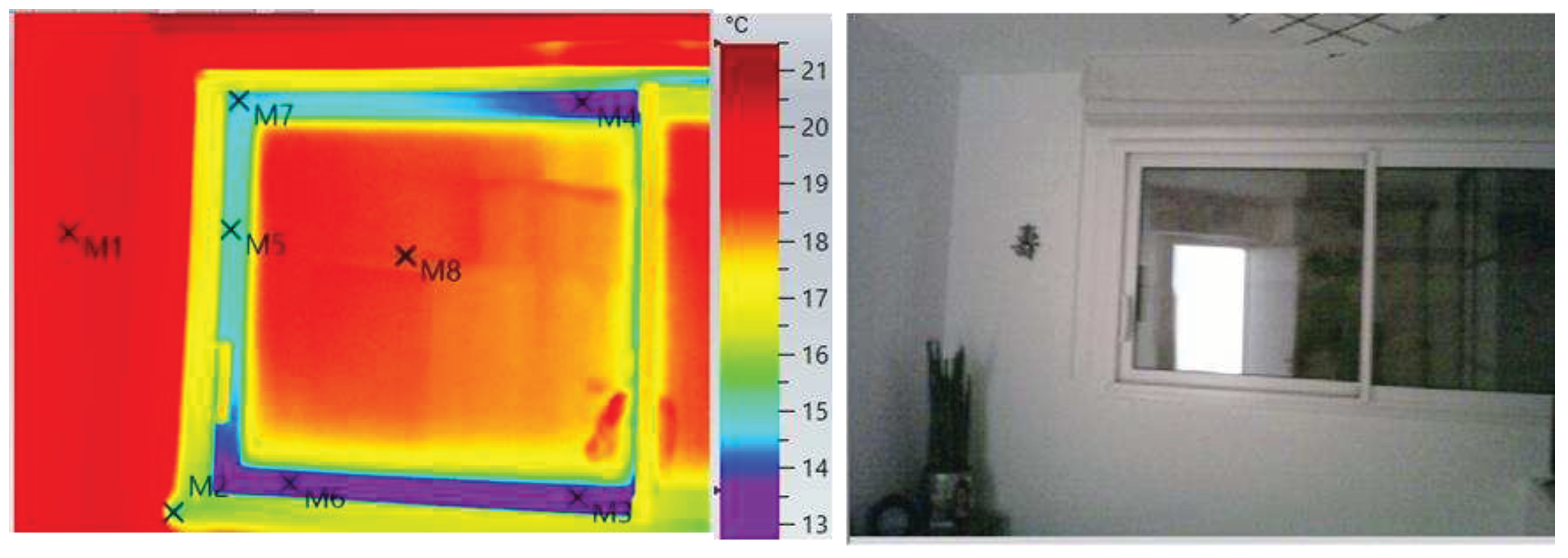
2.1. Infrared radiation & thermograms
When a building is heated during winter season, heat flows through the building components (wall, windows.etc) due temperature difference between inside and outside the building. The resistance to heat flow varies with the properties of the building materials and thickness. This heat flow or leakage can be measured using a heat flux sensors or observed by infrared camera. IR radiation is a type of radiant energy that is invisible to human eyes but that can be felt as heat. Within the electromagnetic spectrum, IR radiation is just beyond the limit of red visible light but above microwaves.
All objects above the absolute temperature (T) emit IR radiation and the quantity of that radiation emitted by the object generally varies with its surface temperature that is proportional to T
4. The amount of IR radiation emitted is also affected by the efficiency of the surface radiating IR also known as emissivity (ε) [
15]. The correlation between IR intensity and temperature is converted to a map of apparent temperature that is based on some assumptions such as variations in emissivity and this is considered in another section below. The thermal images from the thermal camera is known as thermograms and calibrated temperature thermal images is denoted as thermography. An example of a thermogram is indicated in
Figure 1.
The scale and numerical values beside the image shows the relative temperatures due to different colors in the image.
When thermograms are reproduced with a temperature scale the apparent temperature can also be seen at each point. There are several sets of palettes that are commonly used to show the temperature differences. In this study, the rainbow palette is used as indicated in
Figure 1. The minimum temperature in the image is indicated by the lowermost value on the temperature scale and the maximum temperature is indicated by the uppermost value.
Areas that are black in the image is at a temperature lower than the lowermost value whereas white parts are warmer than the uppermost value.
2.2. Emissivity
The emissivity of the surface of a material is its effectiveness in emitting energy as thermal radiation. In other words, it describes how well an object emits IR radiation. A black body is a material that is a perfect emitter of heat energy and has an emissivity value of 1. It is calculated as the ratio of the thermal radiation from an object surface to the radiation from an ideal black body radiation at the same temperature. This ratio ranges from 0 to 1. In reality, there are no perfect black bodies and all objects are emitting IR radiation at less than 100% and having emissivity values of less than one. The emissivity varies from object to object and depends upon chemical makeup, geometry and temperature. As all object are imperfect emitters, the total radiation from an object could be a combination of absorbed, transmitted and reflected radiations. Transmitted radiation is the one that passes through the object of interest, reflect radiation is radiation from a source in front of the object and that reflects off the object surface.
Let us consider, an object which is not a black body in an enclosure, a room for example and E watt of radiation falls on each square metre of the body’s surface. If the object absorbs a fraction α of the incident radiation noted as αE (W/m²) and radiation that the object does not absorb is therefore ( E- αE), it reflects or transmits. At equilibrium, the total power leaving the object /m² is equal to the total power falling upon it, E (W/m²). The power emitted by the object that must be added to that reflected and transmitted is therefore αE (W/m²). The ratio of the total power radiated/m² of the object, to that emitted by a black body at the same temperature is therefore noted as ε = αE/E = α. Hence, at thermal equilibrium the total emissivity of the object is equal to its total absorption factor.
Moreover, most bodies are colored they transmit or reflect some wavelengths better than others. They must absorb these wavelengths weakly and must radiate them weakly. Kirchhoff [
16] showed that the spectral emissivity of a body, for a given wavelength, is equal to its spectral absorption factor for the same wavelength, then ε
λ = α
λ. In this study and for a perfect use of the thermal camera, this factor, reflected temperatures and environmental conditions are considered for a correct interpretation of thermal images.
2.3. Indoor assessments
Materials with a high emissivity show their true temperature better than those with low emissivity. Common building materials such as brick, concrete and paint have a high emissivity of around 0.9. Hence, before internal measurements with the IR camera of each zone in the building, all objects and environments were considered at thermal equilibrium of the IR camera. Hence, the emissivity value is set to one ( ελ = αλ ) on the IR camera and internal or reference temperature should always be indicated for all thermograms. The angle of view is always perpendicular to the measured radiation as IR radiation is reduced and temperature can be underestimated for measurements further from the perpendicular. For this study case, the room temperature was at 21°C, 40% internal humidity and outside temperature was at 5°C during the winter season.
2.4. Thermal camera
Infrared cameras are sometimes called black bodies and have integrated temperature control electronics. There is a wide range of IR camera and they differ in thermal sensitivity, image resolution. For this study, the IR camera that had been used is the professional measuring instrument Testo 885. It is a Testo super Resolution technology with 640x480 pixels, thermal sensitivity < 30 mK and a spectral range from 7.5 to 14 μm. The field of view / minimum focus distance is given for different lens such as 30°x23°/ 0.1 m and 11° x 9° / 0.5 m. The output visual image size is 3.1 MP for a minimum focus distance of 0.5 m. It can also display real image. The IR camera is also equipped with radio humidity probe for automatic humidity measurement and value transfer in real time. The high quality IR measurement system means that energy losses or thermal bridges in buildings can be reliably detected
2.5. Temperature Index
Cold surfaces naturally tend to be the first surfaces to experience condensation. One of the best metrics for assessing the condensation risk is the Temperature Index (TI) of a specific detail. TI is a dimensionless factor that defines the thermal performance of an area of building wall and can be calculated for a surface area on the thermal image. The TI that is used as an indicator of the likelihood of condensation is defined as follows:
where,
Tsi = Internal surface temperature
Ti = Internal ambient temperature
T0 = External ambient temperature
For dwellings the value of TI should not be less than 0.75. In this study, TI should be applied to a zone of missing thermal insulator.
3. Thermal Bridges
Thermal bridging in building construction occurs when thermally conductive materials penetrate through the insulation creating areas of significantly reduced resistance to heat transfer. Thermal bridges can take place at different locations of the building envelope and can result in increased heat flow, causing added transmission losses, lower inner surface temperatures and possibly moisture problems. Most often, thermal bridges are created at the level of floor to wall, door to wall junctions, roof to wall junctions, ceilings to wall junctions and openings to the outside such as doors or windows. In this paper, we should consider thermal bridges, mainly wall to wall junctions, balcony to wall junctions and due to window frames. As already indicated, one of the effects of thermal bridges is increased heat loss through the wall, leading to higher operating costs. But, in this study case, detection of cold at the thermal bridge locations is leading to occupant discomfort, health and safety issues. Also, the design office that has issued the energy performance certificate has neglected thermal bridges at balconies, resulting in an under estimation of the total heat flow through the building envelope.
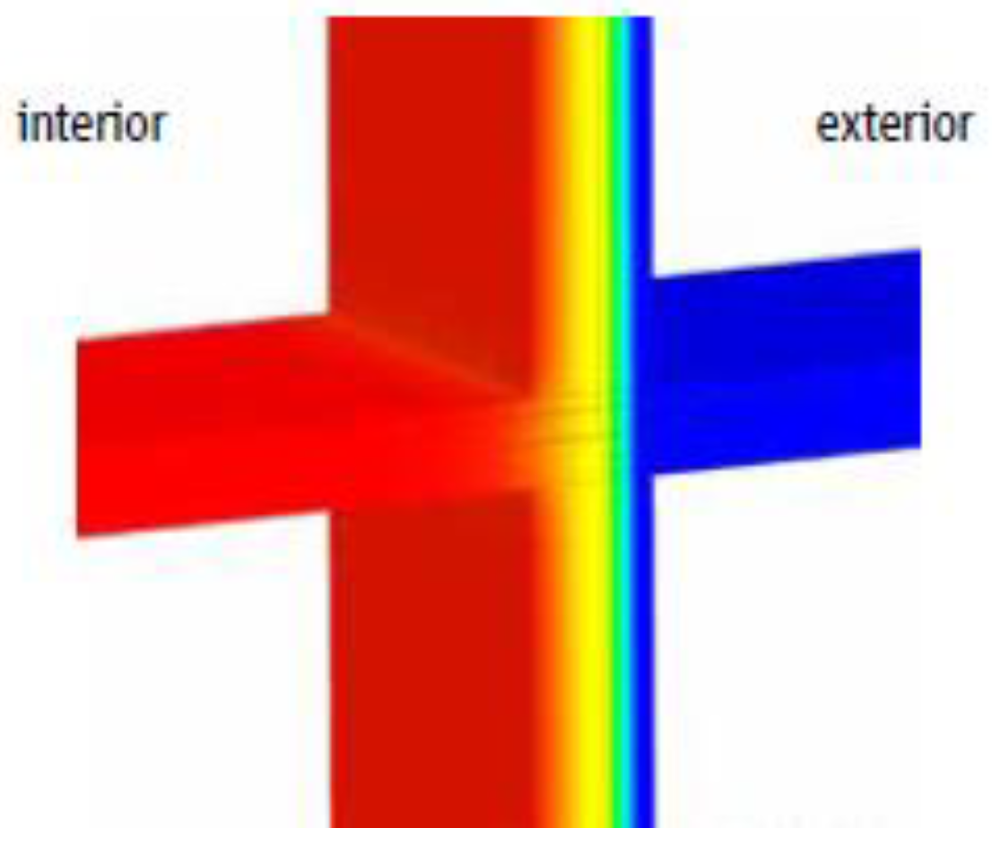
The thermal bridge effect at a vertical wall and balcony which is an extension of the concrete ceiling without thermal break is modelled [
17] in
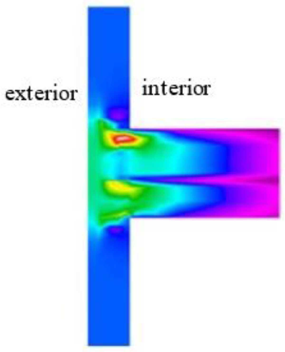
Figure 2. In that figure, the red surface is the inner warm surface while the blue surface is the outer one; the color gradient from yellow to clear blue is showing heat flow to the outside through the balcony slab and the linear thermal bridge is the one that is measured by thermal camera. The temperature model distribution with thermal break is illustrated in
Figure 3. In that figure, thermal break is providing a continuous insulating layer and has significantly reduced heat loss.
A number of numerical and experimental research studies [
18] are published on finding solutions to reduce the heat loss across the balcony slabs.
They also neglected the thermal bridge effect at a concrete beam embedded in an external wall as represented in
Figure 4. In this study case, the considered building has cantilevered balconies which is the most critical thermal bridges in a building envelope and more when cantilevers are non-insulated.
Figure 5, illustrates a real image of the regarding building for this study case with cantilevered balcony. The concerning apartment is the upper ground floor indicated by the blue frame in
Figure 5.
The main interest is impact of thermal bridge details on the building performance. Therefore, the effects of thermal bridging transmittances must be included in whole building energy performance that is initially determined by the design office using the appropriate linear heat transmittance () and point heat transmittance () factors. The effective heat transmittance (U) that must be used is written as follows:
where UEP is the initial transmittance value determined in the energy model or calculation and n is the number of point thermal bridges (PTB) in the analysis area and A is the total surface area. Further explanation can be found in literature [
19]. However, in the experimental section we should not consider PTB as they were not observed during IR thermal survey.
4. IR measurements
The considered building for this study case is illustrated in
Figure 5 and is supposed to be an example of a latest high performance building in France as it was finished in year 2021. The building is in the north-east of France which has a semi-continental climate characterized by cold and grey winters, accompanied by frequent snowfalls. The average temperature of the coldest months is nearly 1°C. There can be cold spells, in which temperatures can drop as low as -10°C or even below. Experimental conditions for the IR measurements are indicated in section 2.3. The architectural design of the concerning apartment is illustrated in
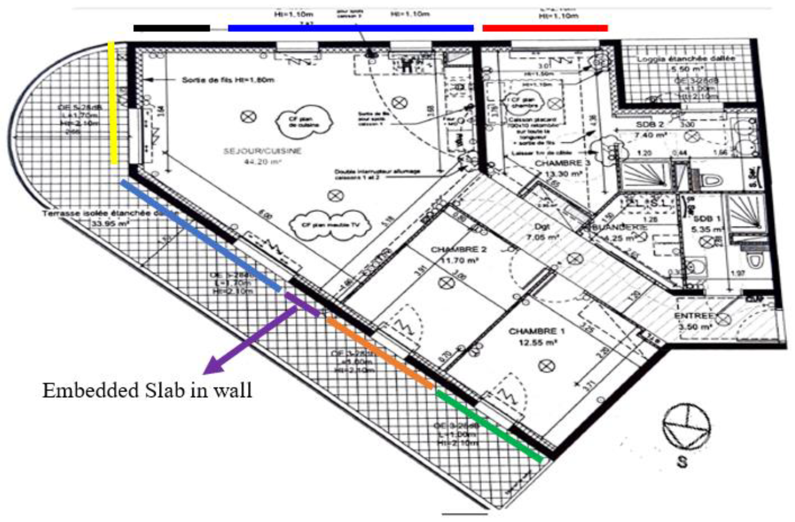
Figure 6 with internal insulation and the total surface area is 110 m². The colored lines should indicate IR thermal measurements zones and orientations at each step of this study.
4.1. Wall to wall thermal bridge
The wall to wall thermal bridge is the master bedroom, having a north orientation, and indicated by the red line in
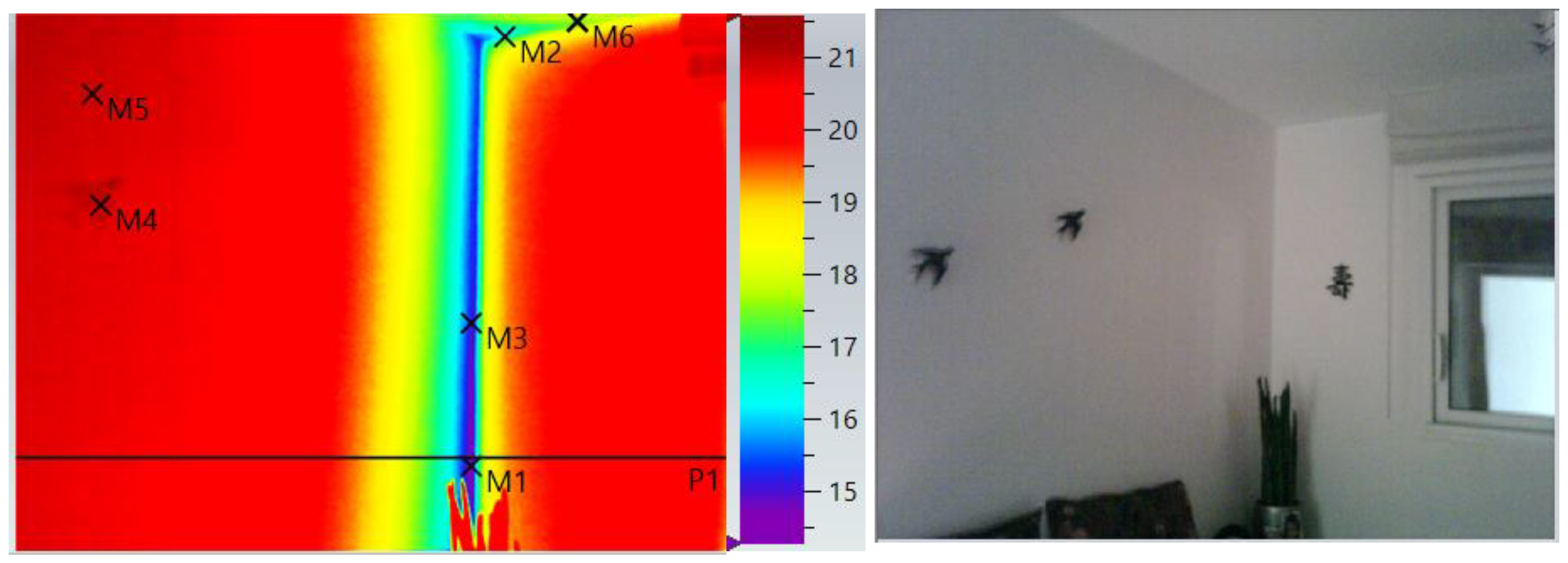
Figure 6. The thermogram is showed in
Figure 7a and the corresponding real image is illustrated on the right side to the thermal image.
The wall containing the window in the real image is an insulated wall facing the outside and is at a junction with an internal load-bearing wall.
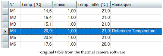
The blue color in the IR image indicates the wall to wall thermal bridge. The black bird which is a dark object is considered as the reference (reflection) temperature at 20.9°C and the measured room temperature is 21°C indicating that measurements are done in an optimal condition. M1 to M5 in the thermogram, are measured temperatures by IR camera as indicated in
Table 1. The reference temperature is M4 (black object) as indicated by the highlighted blue line in
Table 1 and M1 is the lowest temperature at 14.6°C. M5 is a random point showing that the red color is at the reference temperature.
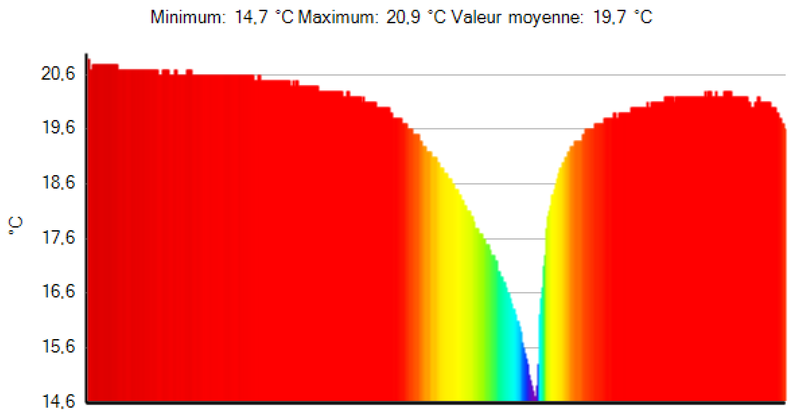
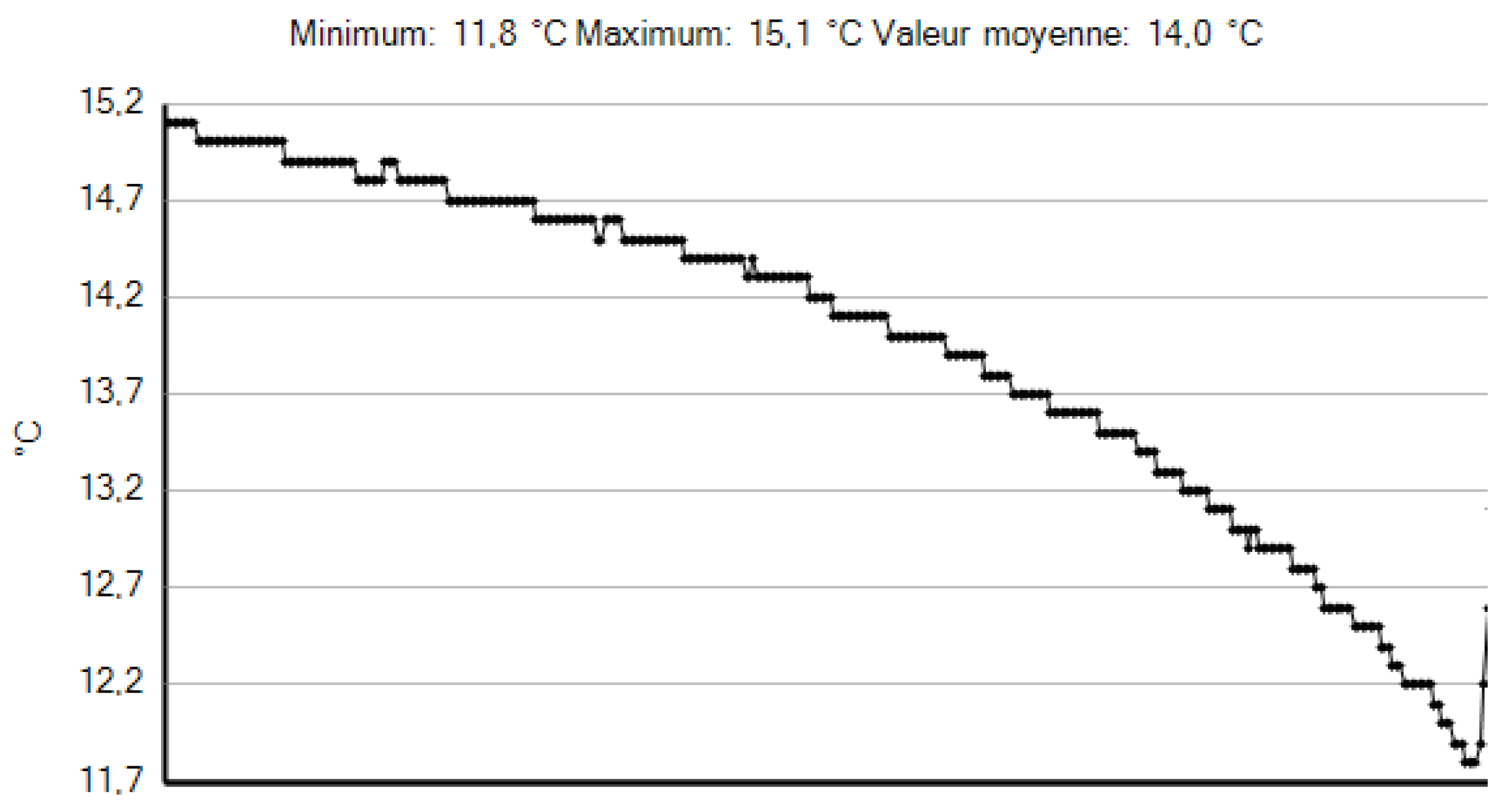
The line P1 in the thermal image is the temperature profile and plotted in
Figure 8, showing a substantial temperature drop.
It is also interesting to point out that temperatures M2 & M6 are part of the balcony thermal bridge.
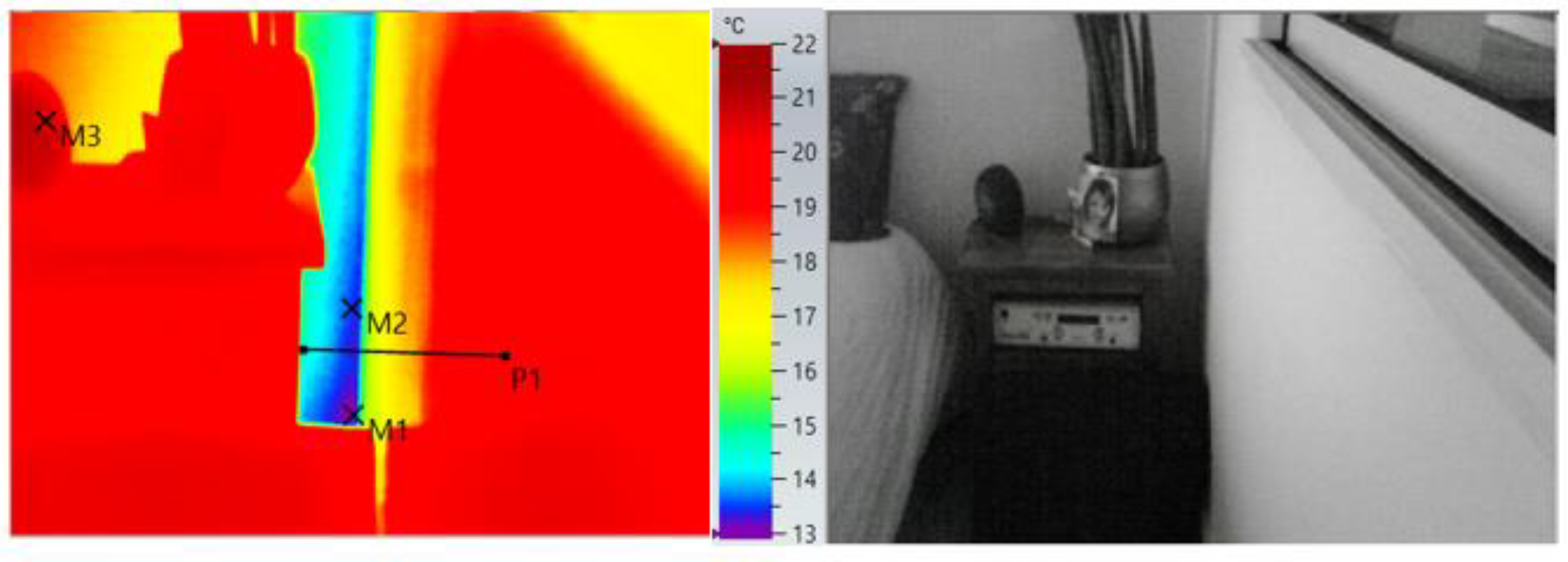
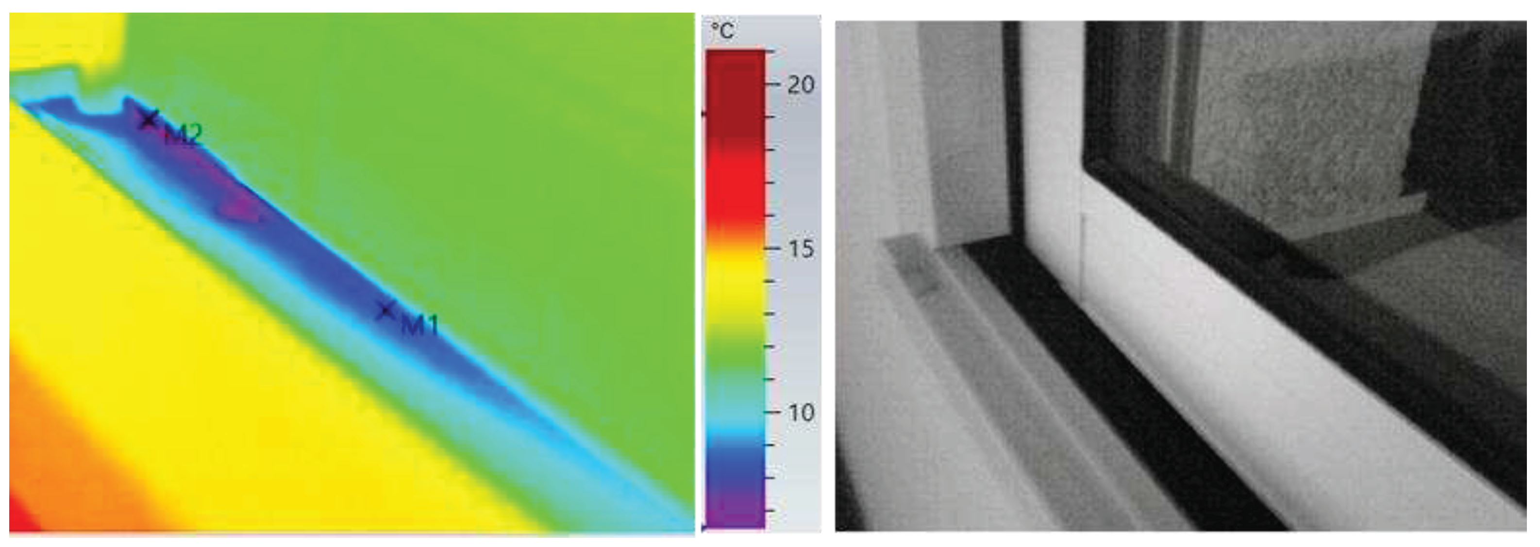
The lower part of this wall to wall thermal bridge is showed in
Figure 9 with the corresponding real image. In
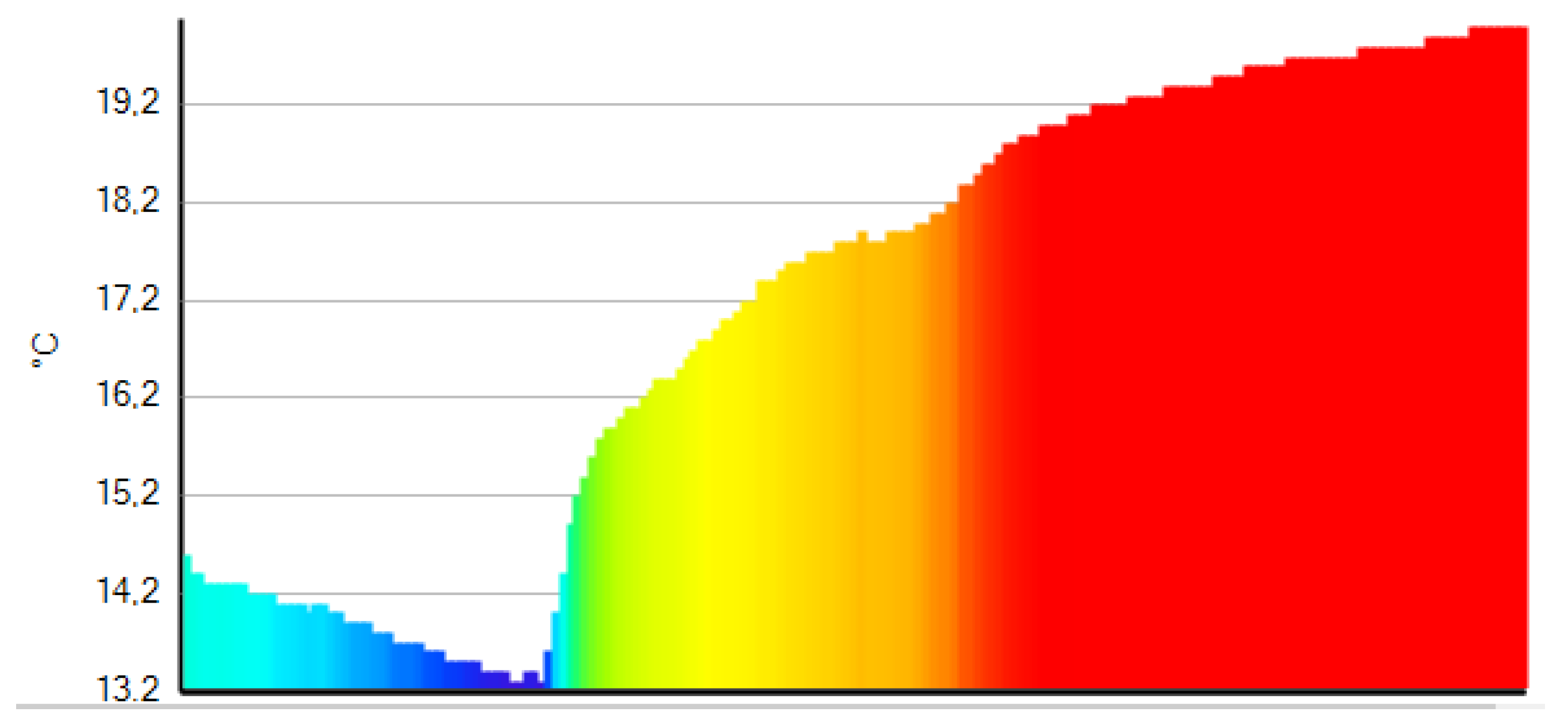
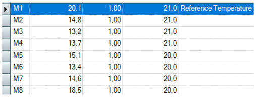
Table 2, the lowest measured temperature is close to 13°C indicated by M1, for a reference temperature 20.8°C indicated by M3, which is a dark alarm clock in the real image. Line P1 in the thermal image is the profile temperature that is plotted in
Figure 10. The difference between the reference temperature and lowest temperature in the thermal bridge is 7.9 °C.
This thermal bridge is caused by a lack of extension of the insulation on the uninsulated wall or a missing of thermal break at the walls junction during construction. The colors in the thermal image have been standardized in the Testo software for a better overview of temperature variation.
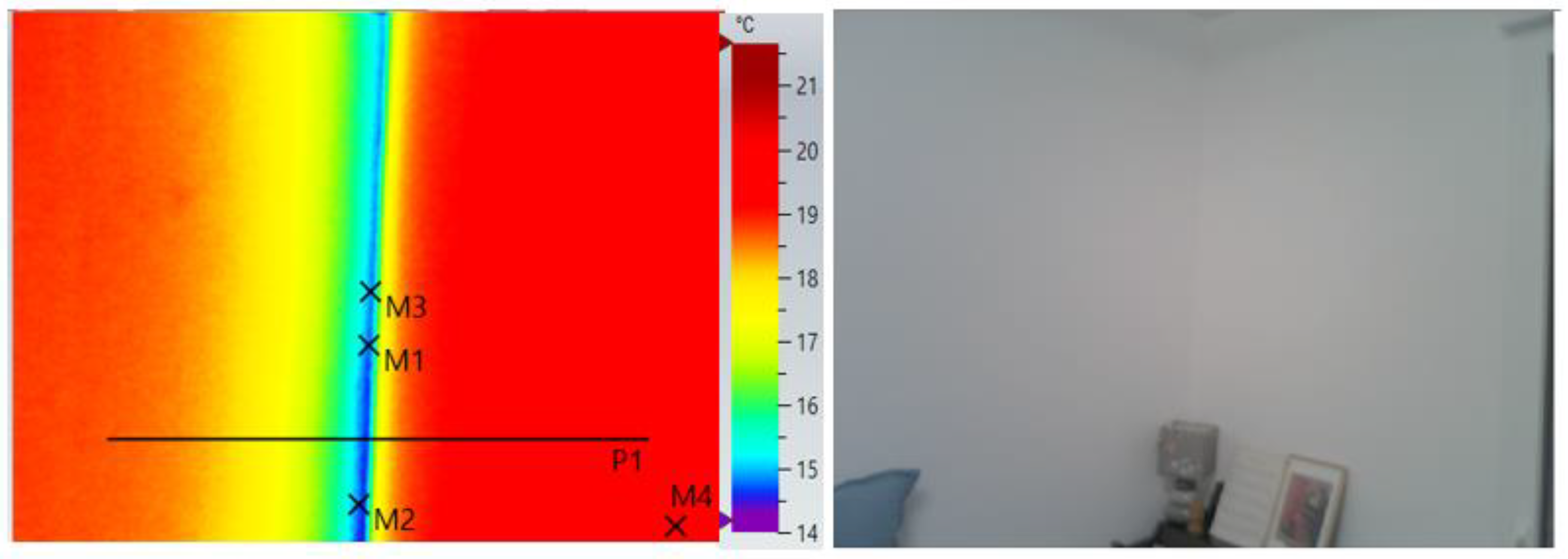
The next wall to wall thermal bridge is in another bed room, the green line in
Figure 6. The thermal bridge again is at the junction of the internal bearing wall and an insulated wall facing the outside but in a south orientation. The thermograms and corresponding real image are displayed in
Figure 11.
Table 3, is indicating temperatures at variant locations in the thermal image. The temperature difference is nearly 5°C between the lowest temperature in the thermal bridge and the room temperature.
4.2. Balcony to wall junctions
Traditionally, balconies have been constructed by extending the concrete slab through the wall into the outside. Such a balcony design is a prime example of a thermal bridge which allows the heat within the building to easily escape along that concrete slab. In this sub section, IR measurements of balcony to wall junctions should be considered and results should follow the similar presentations as in the previous section.
The positioning of the balcony to the walls is showed in
Figure 5. As there are many balconies to wall thermal bridges all around the colors in
Figure 6, it seems convincing to present the most relevant results.
This first type of thermal bridge is along the dark and yellow lines as indicated in
Figure 5 including the junction between the two walls. The thermogram and its corresponding real image are displayed in
Figure 12.
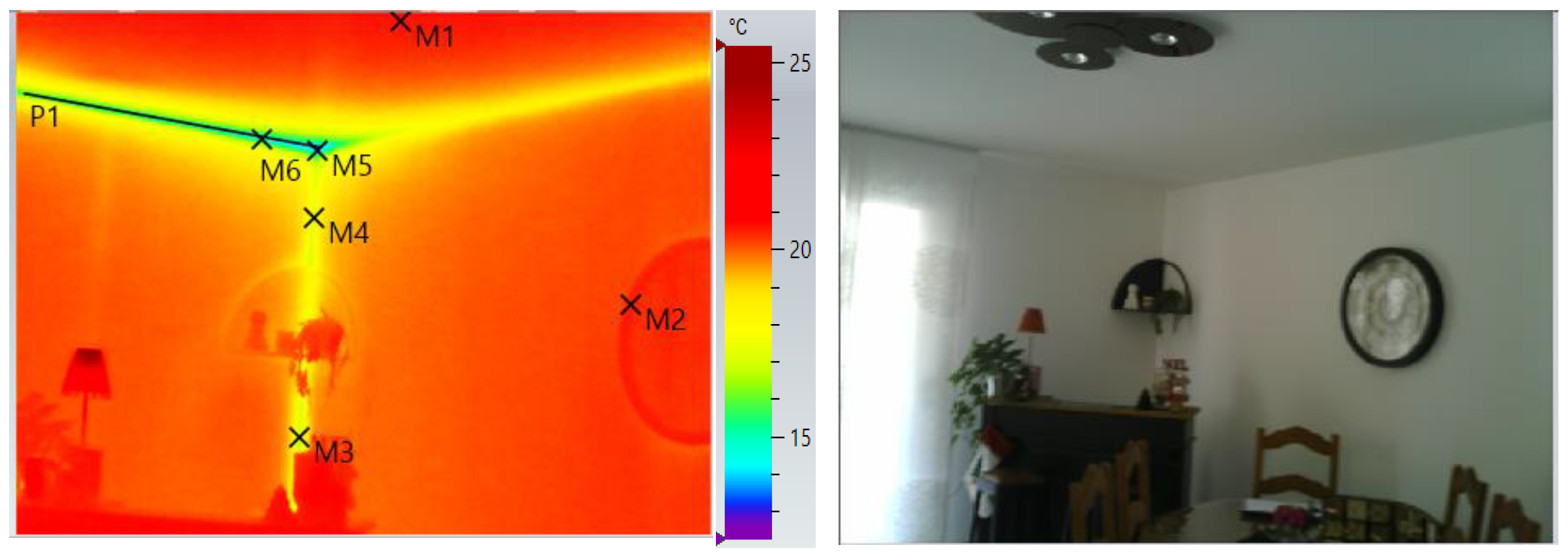
The wall containing the clock in the real image has a north orientation and the perpendicular wall has a north west orientation. The reference temperature is taken as M2 due to the thick dark frame of the clock. It can be concluded that an equilibrium condition is reached as the ceiling temperature M1 is the same as M2.
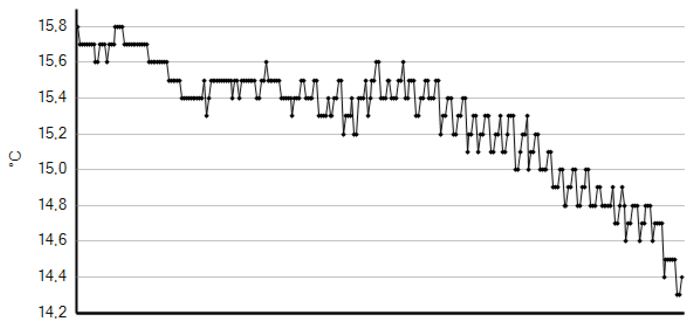
Table 4, gives temperatures at different locations. The least temperature is given at M5 position whereas M3 & M4 are temperatures at the wall to wall junction. Line P1 is temperature profile in the balcony wall thermal bridge and is represented in
Figure 13. The ultimate temperature difference is 7.2°C.
It is clear that there can be no significant representation of temperature profile for the other balcony to wall junction in thermal image as the IR camera was only facing the studied junction. The reason is also specified in section 2.3.
The yellow line in
Figure 6 is the bridge in the north west orientation and above the window door. The concerning balcony and window door are also visible in
Figure 5. The results are presented in
Figure 14 and
Table 5. This thermal bridge is substantial as it still appears even behind the curtain rail in a clear blue color. The greatest temperature difference 5,7°C
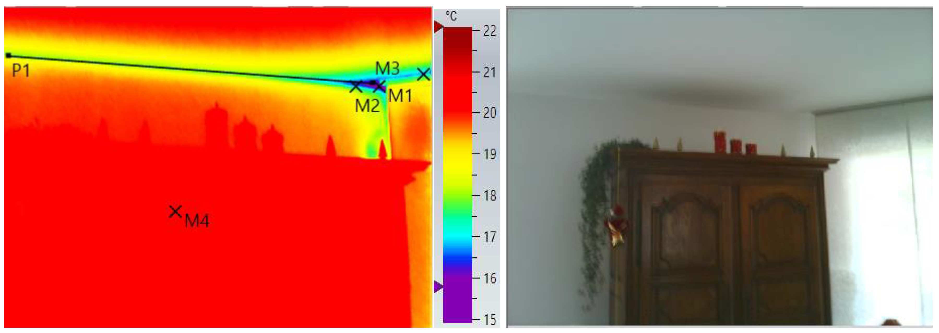
The following results are at the angle between the yellow and clear blue lines, that is between the south and south west orientation. In this case, the line P1 is not very significant as the IR camera in
Figure 15 was facing the angular zone. The plot is simply indicating the temperature drop at the corner.
Table 6 is the corresponding temperatures at several locations in the IR image.
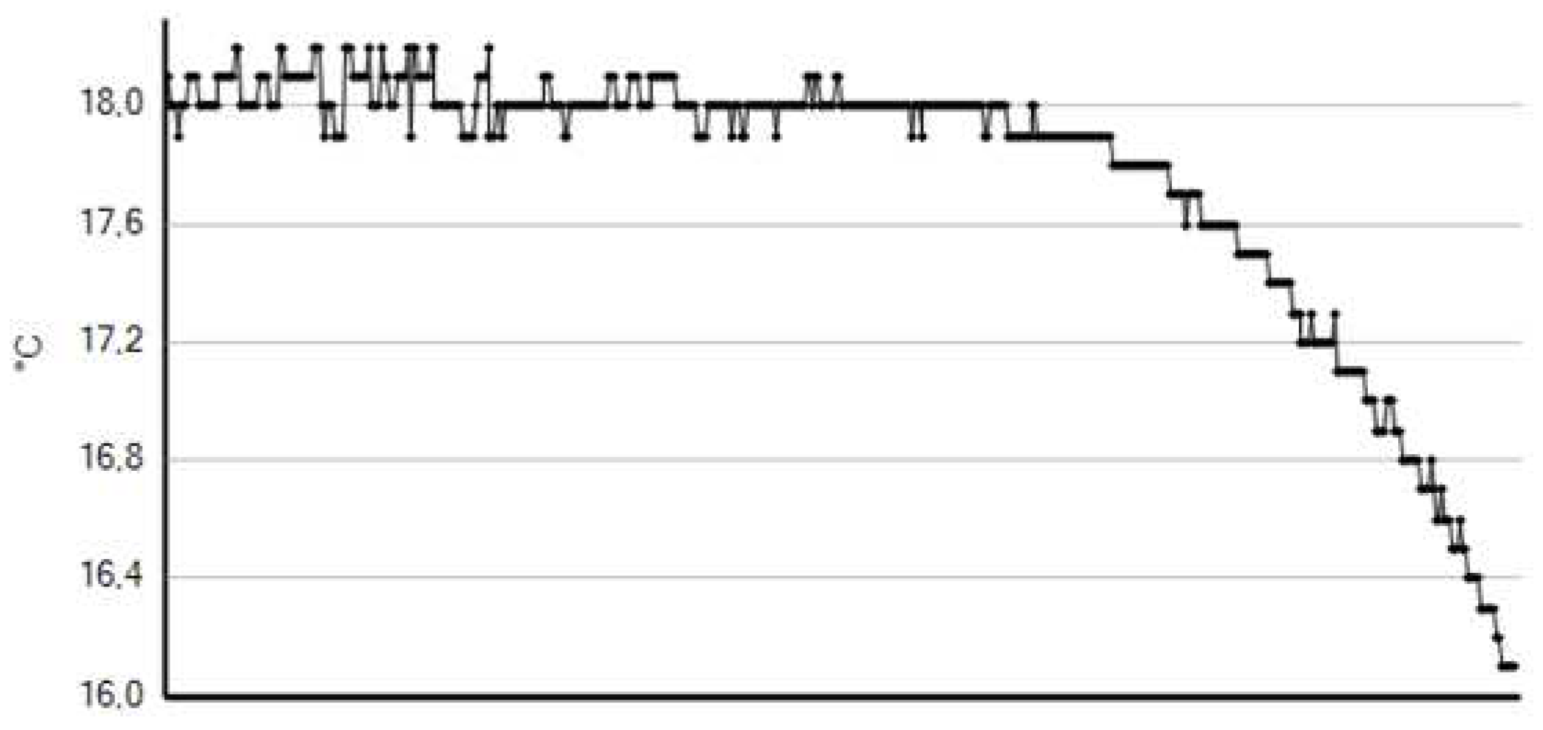
The profile temperature along the balcony thermal bridge facing the south orientation is indicated in
Figure 16. The linear part of the graph is not significant due the IR camera position as explained in section 2.3.
The balcony thermal bridge is all around the building structure and we have chosen to give results for this last junction at the orange line in
Figure 6. This zone has a south orientation. The least measured temperature at M1 position in the thermogram of
Figure 17 is 16.6°C as indicated in
Table 7. The line P1 is the temperature profile along the balcony wall thermal bridge and represented in
Figure 18. We retain a temperature difference of 4.4°C for this thermal bridge.
4.3. Concrete beam to wall junction.
In this sub section, a particular case is presented concerning the embedded beam in a wall. This zone is indicated by the indigo color in
Figure 6. This zone has a south orientation.
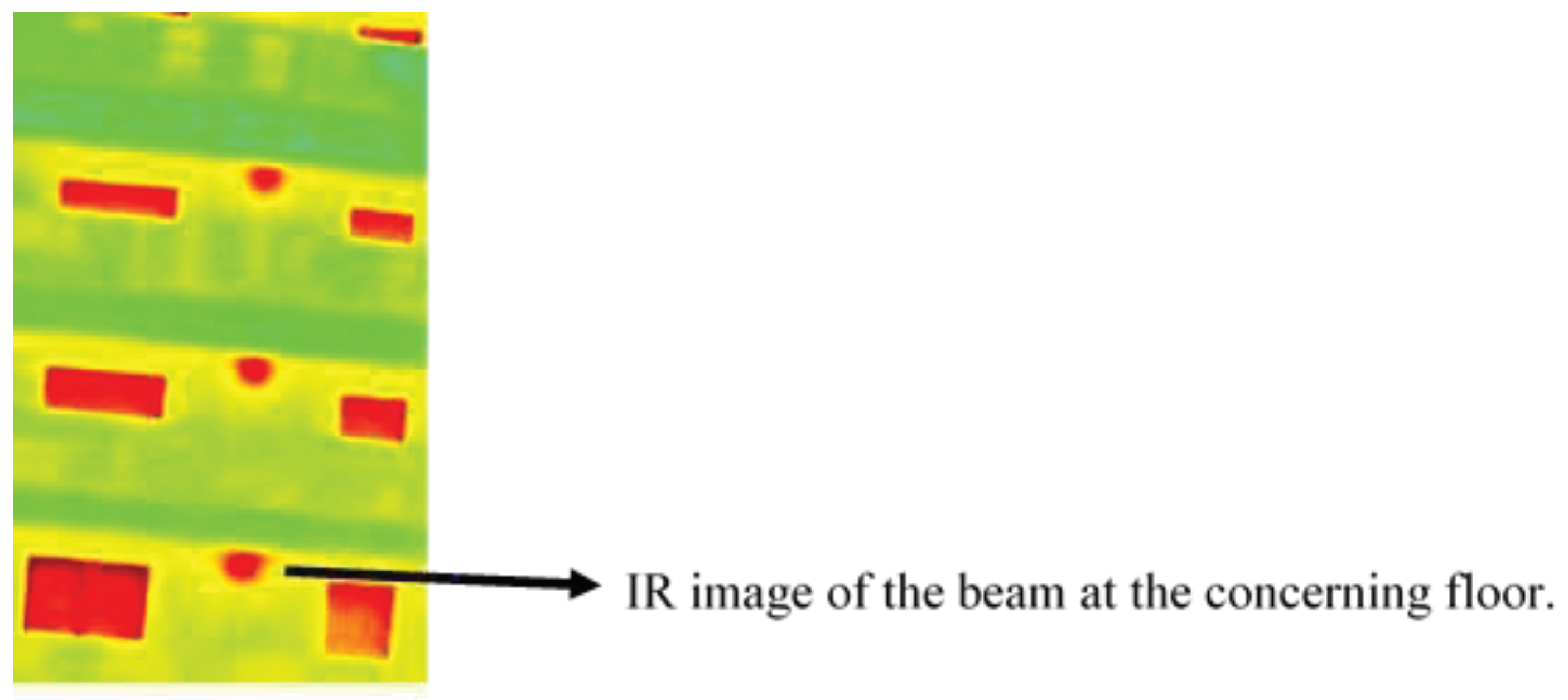
The beam is clearly visible on the outside thermogram at various floor of the building as illustrated in
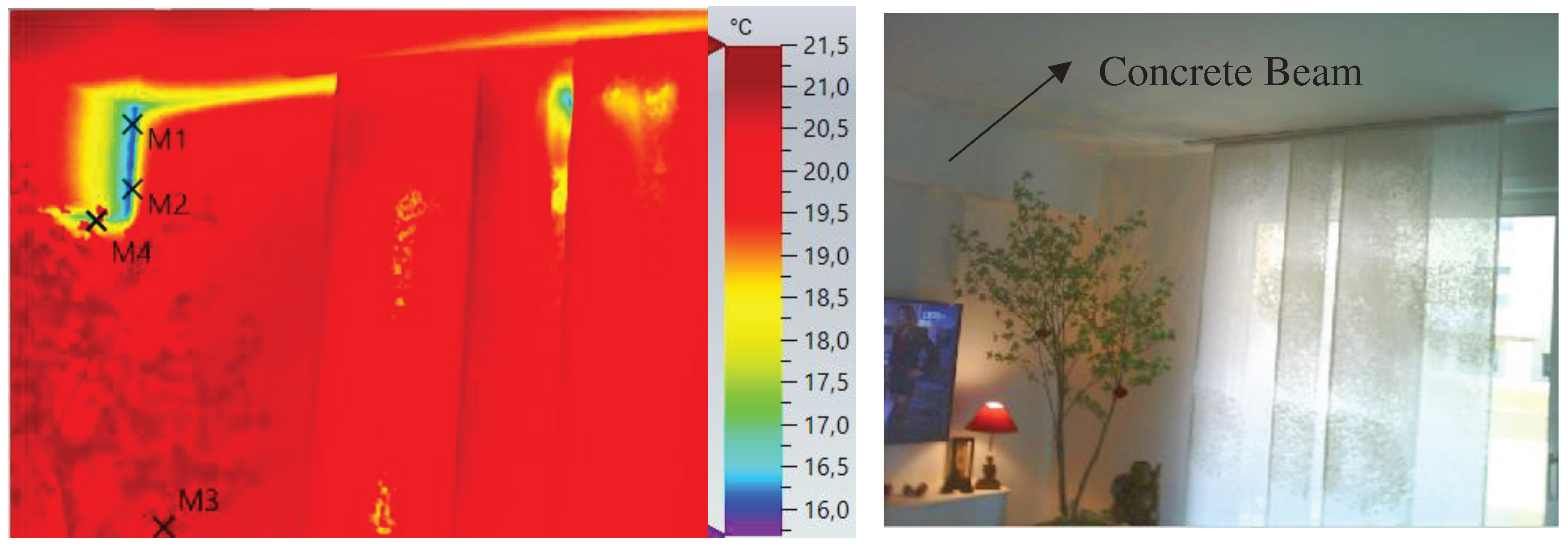
Figure 19. The thermogram of this thermal bridge and the real image are illustrated in
Figure 20.
The corresponding temperatures in the thermogram are indicated in
Table 8.
This thermal bridge was caused by the beam itself and the heat flow is imaged in
Figure 4 of section 3. The reference temperature is determined by the dark object on a branch of the tree in the real image. The maximum temperature difference is nearly 5°C.
4.4. Missing Thermal Insulator
Missing thermal insulator have been listed at few zones of the apartment during the thermal survey. One of the zone is between the yellow and clear blue lines in
Figure 6. It seems that there are missing thermal insulator at various area of the wall and only results regarding the lower part of the wall are considered. We should also consider the temperature index for an area on the thermal image as explained in section 2.5. Internal temperatures at different locations of that zone were also measured by a contact temperature sensor PT 100 and are similar to those of the thermal camera. During this survey, the internal ambient temperature, Ti, was 21°C and the external ambient temperature T
0 was 5°C. Various parts of missing thermal insulator are visible on the thermogram of
Figure 21 and the corresponding real image on the right of the thermal image. The measured internal surface temperatures are given in
Table 9.
M3 is considered as the internal surface temperature Tsi at 16.1°C for the temperature index determination given by equation 1 in section 2.5 and the other temperatures in this equation are indicated above. The determined TI value is 0.694.
For dwellings the value of TI should not be less than 0.75 as this value matches an internal surface temperature of 13.8 °C when the usual inside temperature is 20°C and outside temperature is -5°C. Consequently, condensation would arise if the outs ide temperature was below -5°C or the inside air was more saturated with water vapour.
4.5. Heat loss by thermal break windows.
All the apartments of this new dwelling are equipped with double glazed windows filled with an inert gas such argon or krypton and are essentially thermal break insulated aluminum windows. Thermal breaks are a material placed inside the aluminum window frame to minimize heat loss through the frame. They are able to cut this heat flow because they are also made up of materials that can interrupt thermal conductivity. This material is usually PVC.
Therefore, windows thermal survey has been performed by the thermal camera for heat loss detection or air leakage. In this section, only relevant results are presented.
The following results are for the window in the master bedroom, red line in
Figure 6.
The window is facing the north. The window thermogram is illustrated in
Figure 22.
Measured temperatures at various positions of the window are given in
Table 10. M1 is the reference temperature. The M2 temperature is at 14.8°C indication a small air leakage due a poor installation. M3 to M7 are temperatures around the window frame showing low temperatures comparing to the reference temperature. The colder the window frame the greater the conductive current and this great temperature difference is always causing air movement cycle that is felt a lot like a window draft by occupants. The constant cold surface temperatures make the bedroom especially unpleasant and uncomfortable and on end having major effects on quality of life. Moreover, the IR image of
Figure 23 is illustrating an air leakage by the purple color at the bottom part of the window sash.
Table 11, shows temperatures at the cold-air leaks surrounding the sash.
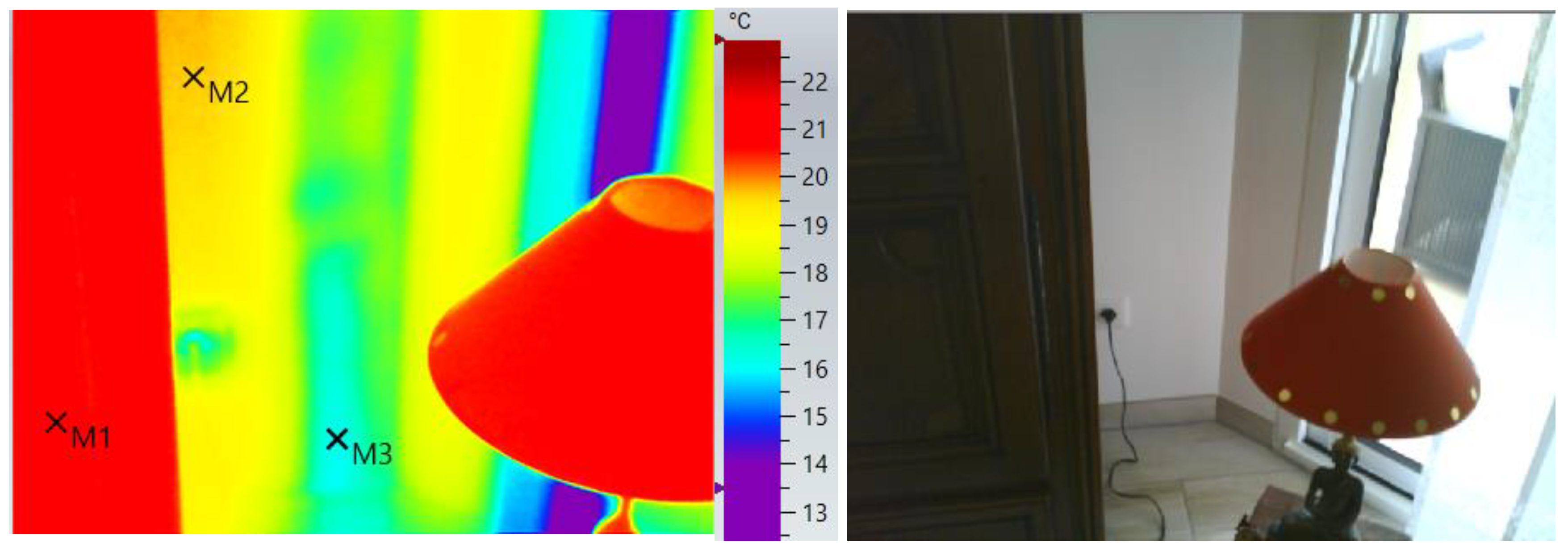
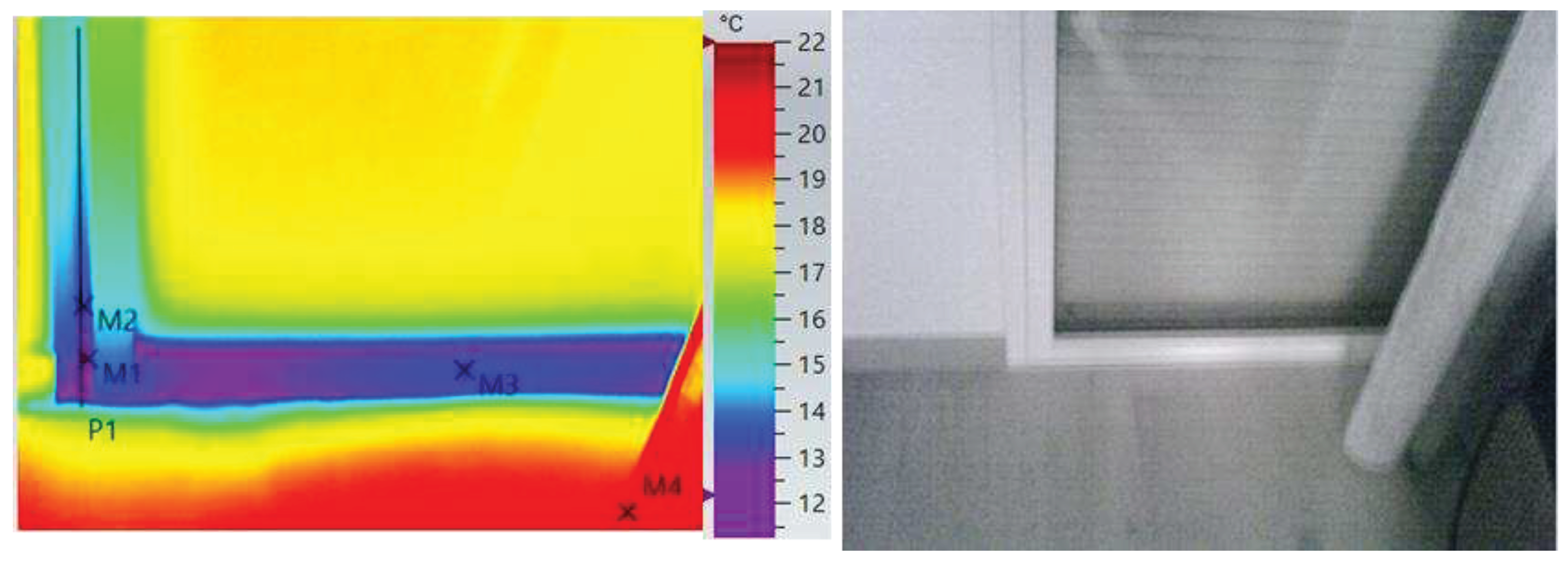
Figure 24, is the thermogram of a window door of the room indicated by the orange line in
Figure 6. The thermogram, is not only showing low temperatures at the bottom part of window frame but also air leakage along line P1 and the temperature profile is indicated in
Figure 25.
Table 12, are temperatures at the window door frame.
4.6. Air speed at window door.
In face of the unexpected temperature profile in
Figure 26, it seems interesting to perform another test at the windows to highlight the air leaking. A wireless smart probe such as Testo 405i thermal anemometer has been used to measure the air speed around all the windows. The probe position was initially determined in the thermal image such the one along line P1 in
Figure 25 and as illustrated in
Figure 26. The air speed was measured between 10 minutes and two hours.
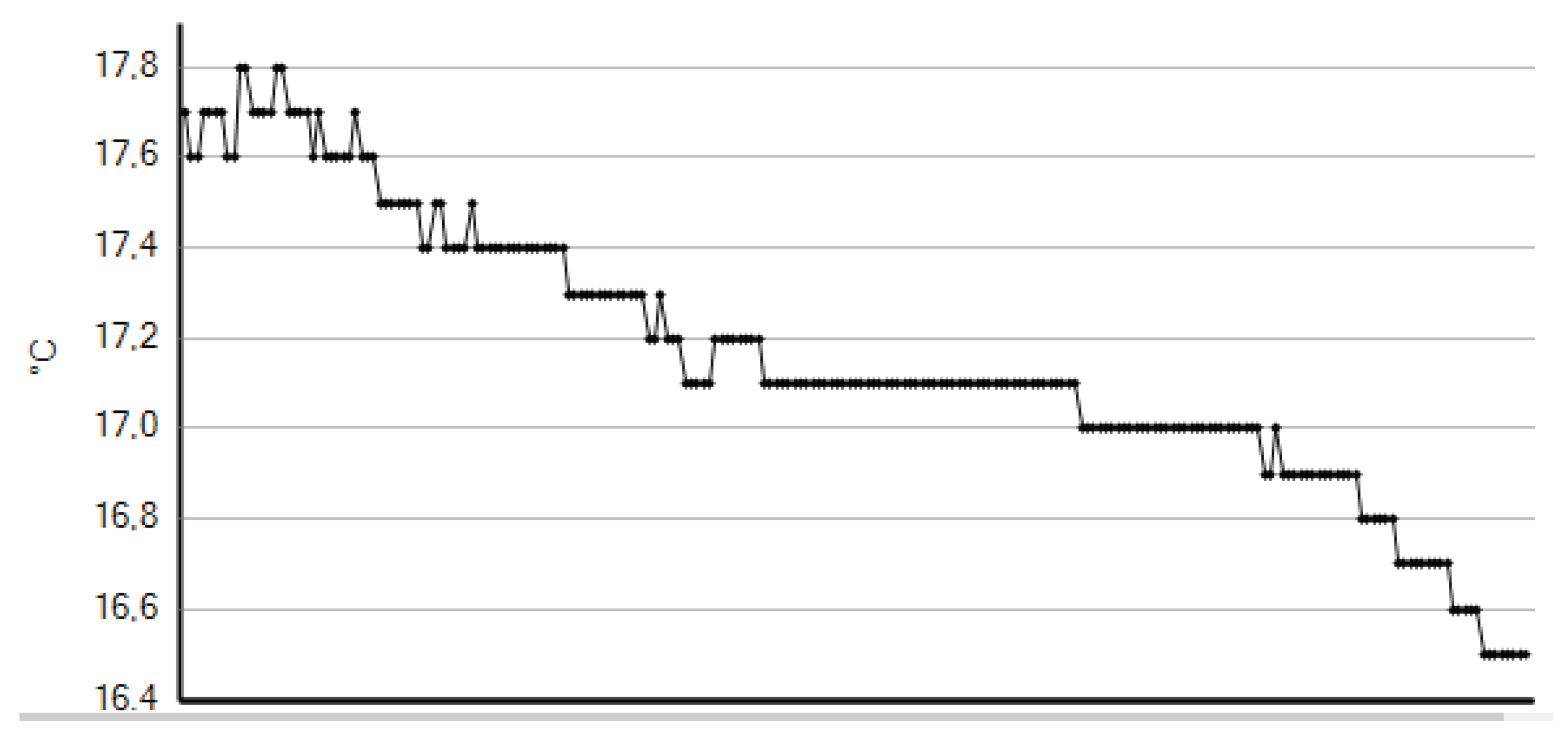
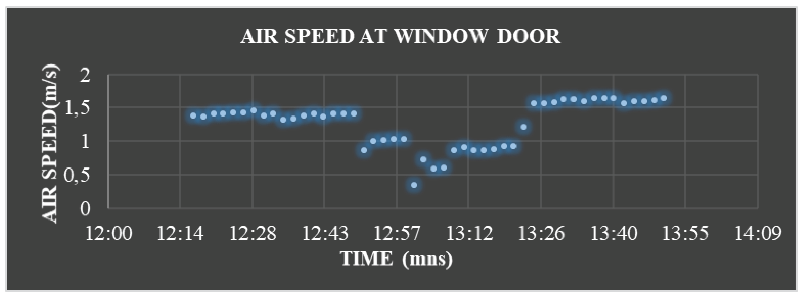
Only two relevant results are presented. The first one is along the window door at the orange line in
Figure 6. The air speed was measured for more than two hours as illustrated in
Figure 27 and it can be observed that the air speed difference is between 0.5 m/s to 1.6 m/s.
The other test was performed on the window door which is at the yellow line in
Figure 6, in a north west direction. The air speed was measured for nearly 10 minutes and is represented in
Figure 28. We can see that the maximum air speed is closed 1 m/s. Hence, these results attest that there exists an air leakage at some window doors.
4.7. Heat transmittance results
In France and in the national regulations for new building exigencies intended for Ψ, the linear transmittance thermal bridges, between intermediate floors and facades should be less than 0,6 W/m K. Also, the overall linear thermal transmission ratio , Ψ
T = Σ(Ψ,L) / (Building overall Floor surface) , of the whole building must be less than 0,28 W/m²(
floor surface) K. However, there is no specification for Ψ, in the national regulations when the slab is an extended balcony slab with a concrete to concrete intersection. Therefore, for an estimation of power transmission loss (PTL) for this study case, we are comparing the PTL for two different Ψ values in
Table 13. The first column represents the expected results in the France national regulation RT 2012. The second column is the PTL value using the linear transmittance Ψ = 0,6 W/m K but with a mean difference temperature of 4°C as measured by the thermal camera at the balcony thermal bridge. The third column is similar to the second column but with Ψ = 0,805 W/m K as determined in [
20]. The fourth column is the PTL due to thermal bridge at wall to wall for a mean temperature difference of 5°C with Ψ = 0,3 W/m K as considered in the national regulation software. The total length of balcony thermal bridge is 26,76 m and the total height of wall to wall thermal bridge is 5 m. The total floor surface area is 110 m².
Therefore, for this study building and considering the overall linear thermal transmission ratio ΨT of the whole building in RT 2012, then the overall power loss per m² is equal to 0,207 for RT2012, whereas it is equal to 0,645 when Ψ = 0,6 W/m K and equal to 0,843 when Ψ = 0,803 W/m K. This requirement in the national regulations is not met.
5. Conclusions
This study assessed the influence of thermal bridges on heat losses in an internal insulation layers’ apartment of a recent building using IR thermography which is a non-destructive method in building sector. The thermal camera was used in optimal indoor conditions and the most appropriate method was applied for this thermographic survey. It has been highlighted that junction between an external insulated wall and an internal non-insulated wall has not lead to a significant reduction in the heat losses but has increased the thermal bridging beside the augmentation in the cost of construct. In this paper, a great part of balcony thermal bridge has been considered comparing to all other thermal bridges, as the former present a large cross-sectional area ratio of the exterior building envelopes and has a greater negative impact on the energy performance. It is also emphasized that heat loss in the high-rise building is due to non-insulated concrete slab such as balconies. Air pressurisation using the blower door had allowed the building to pass the airtightness test. However, thermography of thermal break windows had revealed air leakage and quantified by measurement with a thermal anemometer probe and where the air speed was nearly 1,5m/s. So, this study has underlined the occurrence of thermal bridges due to faulty execution causing heat lost, occupant discomfort and in long run may affect the indoor climate. Moreover, there is noncompliance in the national regulations as some exigencies, such as the overall linear thermal transmission ratio, are not met.
It is clear that thermal bridges are regarded in all national regulations for new buildings of all states of the European Union. However, thermal bridges and energy consumption inspections during and after the building process especially for large buildings are not regular and mandatory processes. As for some recommendations, energy specialists should do inspections by taking measurements, pictures before, during and after the building process. The number of blower door test need greatly to be increased for buildings. One of the most widely recommended solutions to the balcony slab thermal bridge problem is to introduce thermal breaks or insulated concrete curbs and make it compulsory in thermal regulation. New building specifications should include a clause specifying thermal imaging as a means of quality assurance.
Figure 1.
Example of a thermal image.
Figure 1.
Example of a thermal image.
Figure 2.
Heat flow through balcony slab.
Figure 2.
Heat flow through balcony slab.
Figure 3.
Heat flow with thermal break.
Figure 3.
Heat flow with thermal break.
Figure 4.
Embedded beam in a wall.
Figure 4.
Embedded beam in a wall.
Figure 5.
Real image of the concerning building at upper ground.
Figure 5.
Real image of the concerning building at upper ground.
Figure 6.
Architectural plan of the apartment in the case study building.
Figure 6.
Architectural plan of the apartment in the case study building.
Figure 7.
Left is the thermogram of a wall to wall thermal bridge and real image on the right.
Figure 7.
Left is the thermogram of a wall to wall thermal bridge and real image on the right.
Figure 8.
Substantial temperature drops due to wall to wall thermal bridge.
Figure 8.
Substantial temperature drops due to wall to wall thermal bridge.
Figure 9.
Lower part of the wall to wall thermal bridge.
Figure 9.
Lower part of the wall to wall thermal bridge.
Figure 10.
Profile temperature of line P1 in the thermal image.
Figure 10.
Profile temperature of line P1 in the thermal image.
Figure 11.
On the left, another wall to wall thermal bridge and the real image on the right.
Figure 11.
On the left, another wall to wall thermal bridge and the real image on the right.
Figure 12.
Balcony wall thermal bridge on the left and real image on the right.
Figure 12.
Balcony wall thermal bridge on the left and real image on the right.
Figure 13.
Temperature profile in the thermal bridge in the IR image.
Figure 13.
Temperature profile in the thermal bridge in the IR image.
Figure 14.
Left: Balcony thermal bridge along the yellow line. The real image on the right.
Figure 14.
Left: Balcony thermal bridge along the yellow line. The real image on the right.
Figure 15.
Left: Thermograms between yellow and clear blue lines. Real image on the right.
Figure 15.
Left: Thermograms between yellow and clear blue lines. Real image on the right.
Figure 16.
Temperature profile of P1 in the IR image.
Figure 16.
Temperature profile of P1 in the IR image.
Figure 17.
Figure 17. Left: Thermogram of the room at orange line and the corresponding real image on the right.
Figure 17.
Figure 17. Left: Thermogram of the room at orange line and the corresponding real image on the right.
Figure 18.
Temperature profile along the thermal bridge in the thermogram.
Figure 18.
Temperature profile along the thermal bridge in the thermogram.
Figure 19.
Beam wall thermogram from outside.
Figure 19.
Beam wall thermogram from outside.
Figure 20.
Thermogram and real image of the slab wall junction.
Figure 20.
Thermogram and real image of the slab wall junction.
Figure 21.
Thermogram of the zone of missing insulator and the real image on the right.
Figure 21.
Thermogram of the zone of missing insulator and the real image on the right.
Figure 22.
Window thermogram on the left and real image on the right.
Figure 22.
Window thermogram on the left and real image on the right.
Figure 23.
Left: Air leakage at the lower part of the window. Real image on the right.
Figure 23.
Left: Air leakage at the lower part of the window. Real image on the right.
Figure 24.
Left: Thermogram of door window and the real image on the right.
Figure 24.
Left: Thermogram of door window and the real image on the right.
Figure 25.
Temperature profile at P1 in the thermogram.
Figure 25.
Temperature profile at P1 in the thermogram.
Figure 26.
Probe position.
Figure 26.
Probe position.
Figure 27.
Measuring air speed at the window door facing the south.
Figure 27.
Measuring air speed at the window door facing the south.
Figure 28.
Measuring air speed at the window door facing the north west.
Figure 28.
Measuring air speed at the window door facing the north west.
Table 1.
Measured temperature at different zone in the IR image.
Table 1.
Measured temperature at different zone in the IR image.
Table 2.
Measured temperature at the lower part.
Table 2.
Measured temperature at the lower part.
Table 3.
Measured temperatures for another wall to wall thermal bridge.
Table 3.
Measured temperatures for another wall to wall thermal bridge.
Table 4.
Temperature at different locations in IR image.
Table 4.
Temperature at different locations in IR image.
Table 5.
Corresponding temperatures of the thermal image.
Table 5.
Corresponding temperatures of the thermal image.
Table 6.
The corresponding temperatures of IR image.
Table 6.
The corresponding temperatures of IR image.
Table 7.
The corresponding temperature in the thermogram.
Table 7.
The corresponding temperature in the thermogram.
Table 8.
Temperatures at various locations in the thermogram.
Table 8.
Temperatures at various locations in the thermogram.
Table 9.
The corresponding temperature of the thermogram.
Table 9.
The corresponding temperature of the thermogram.
Table 10.
Temperatures at various locations in the thermal image.
Table 10.
Temperatures at various locations in the thermal image.
Table 11.
Temperatures in air leakage.
Table 11.
Temperatures in air leakage.
Table 12.
Lowest temperatures at the window door.
Table 12.
Lowest temperatures at the window door.
Table 13.
Comparing overall thermal transmission of the study building.
Table 13.
Comparing overall thermal transmission of the study building.


