1. Introduction
Interest in Ni-Mn-In alloys is mainly focused on non-stoichiometric compositions, especially on the manganese-enriched Ni2Mn(In, Mn) system. Studies have shown that the structure of unmodulated martensite exists in alloys with a relatively low In content (x ≤ 10) [
1]. With an increase in the content of In (10 < x ≤ 16), the crystal structure of martensite has a long-period layered-modulated structure and is characterized by good magnetically sensitive characteristics. In alloys based on Ni-Mn-In, modulated structures 6M, 5M and 7M were observed [
2,
3]. Therefore, accurate determination of the crystal structure of austenite and martensite is of key importance for controlling the effects associated with martensitic transformations, such as magnetic memory (MM), shape memory effect (SME), magnetocaloric effect (MCE).
When cooled from the melt, alloys with the Heusler (for example X
2YZ, XY
2Z and other) structure can undergo a series of disorder-order transitions A2 → B2 → L2
1 (D0
3, C1
b, and some others) depending on the occupancy of positions between the X, Y and Z sublattices [
4]. Alloys based on the Ni-Mn-In system of a non-stoichiometric composition are prone to decay into an energetically favorable structure with a 2-1-1 stoichiometry and the rest of the alloy, which forms various structures with different compositions. [
5]. Depending on the degree of atomic ordering, it is assumed that the Ni-Mn-In compound will contain structural domains and APB formed during the transition from the partially ordered B2 phase to the ordered L2
1. Therefore, the structural order of the austenitic phases depends on the conditions and cooling rate. The papers [
6,
7] describe methods for the formation of APB in Heusler alloys. In the case of a quenched sample, APBs are formed as a result of a thermally induced order–disorder transition [
7]. Or, in the case of slow cooling with a furnace, APBs mainly develop due to the merging of two neighboring L2
1 ordered regions [
6].
In [
8], the relationship between APB, the structure of magnetic domains, and the functional properties of Ni-Mn-Ga single crystals was studied. The APB density was controlled using various thermal treatments, and the magnetic domains were observed using Lorentz transmission electron microscopy. Slow cooling resulted in low density, air quenching to medium density, and water quenching to high APB density. The pinning of the walls of the magnetic domains on the APB was observed, which led to a one-to-one correspondence between the magnetic domain walls and the APB.
In this work, the influence of the cooling rate on the atomic ordering of the austenitic phase of the Ni-Mn-In system inherited by the martensite structure and, accordingly, on the nature of the martensitic transformation was studied.
2. Experimental Technique and Methods
Polycrystalline samples of the Ni-Mn-In alloy in the form of ingots weighing about 30 g were made from high-purity initial metals Ni, Mn, In (99.99%) by arc melting in an argon atmosphere on a cold hearth with three flips and remelting. For the purpose of homogenization, the ingots were annealed in vacuum at a temperature of 1173 K for 48 hours. The ingots were cooled in two ways: natural (slow) cooling in a furnace to room temperature and rapid cooling into water at a temperature of 288 K (quenching). The nominal composition was Ni46Mn41In13 (e/a = 7.86), which coincided with the average data of energy dispersive spectroscopy (EDX) over the diameter of the spherical ingot. The elemental analysis of the foil was also determined by the EDX method in TEM with an error of less than 1 at. % and it showed Ni44.9Mn39.9In15.2 (e/a = 7.73) for quenched and Ni45.6Mn39.5In14.9 (e/a = 7.77) for slowly cooled samples. Within the margin of error of the EDX, no noticeable signs of oxygen were detected.
The microstructure of the samples was studied in the temperature range 120–300 K using a Carl Zeiss Libra 200FE transmission electron microscope (TEM) (accelerating voltage 200 kV) with an OMEGA energy filter, an Oxford Instruments X-Max 80 energy-dispersive X-ray detector, and a Gatan Model 636 two-axis cryoanalytical holder with Model 900 SmartSet cold stage controller. Foils for TEM were obtained by mechanical thinning with abrasives of various fineness, and further thinning was carried out electrochemically in an ethanol solution of 30% nitric acid at room temperature. The final thinning was carried out in an ion polishing unit with argon ions. The samples for the structural study were ultrathin TEM foils obtained by standard methods. Electron microscopy studies and foils preparation for TEM were carried out at the IRC Nanotechnology, Science Park, St. Pe-tersburg State University, 199034 St. Petersburg, Russia.
The characteristic temperatures of the beginning and end of the forward and reverse thermoelastic metamagnetostructural (hereinafter, for simplicity – martensitic) transformations and the Curie temperature were determined by differential scanning calorimetry (DSC) on a METTLER TOLEDO DSC3+ setup in the temperature range from 100 to 600 K at a speed of 2 K/min and by the thermogravimetric (TGA) method, respectively. The method of thermomechanical analysis (TMA) determined changes in the linear dimensions of the sample as a result of martensitic transformation, thermal expansion coefficients (TEC)
X-ray diffraction studies in the temperature range from 86 K to 573 K were carried out on a Rigaku Ultima IV multifunctional diffractometer using CuKα radiation, a graphite monochromator on a diffracted beam of a scintillation detector, and a low- and medium-temperature attachment LMT (Rigaku, Japan).
3. Results Discussuion
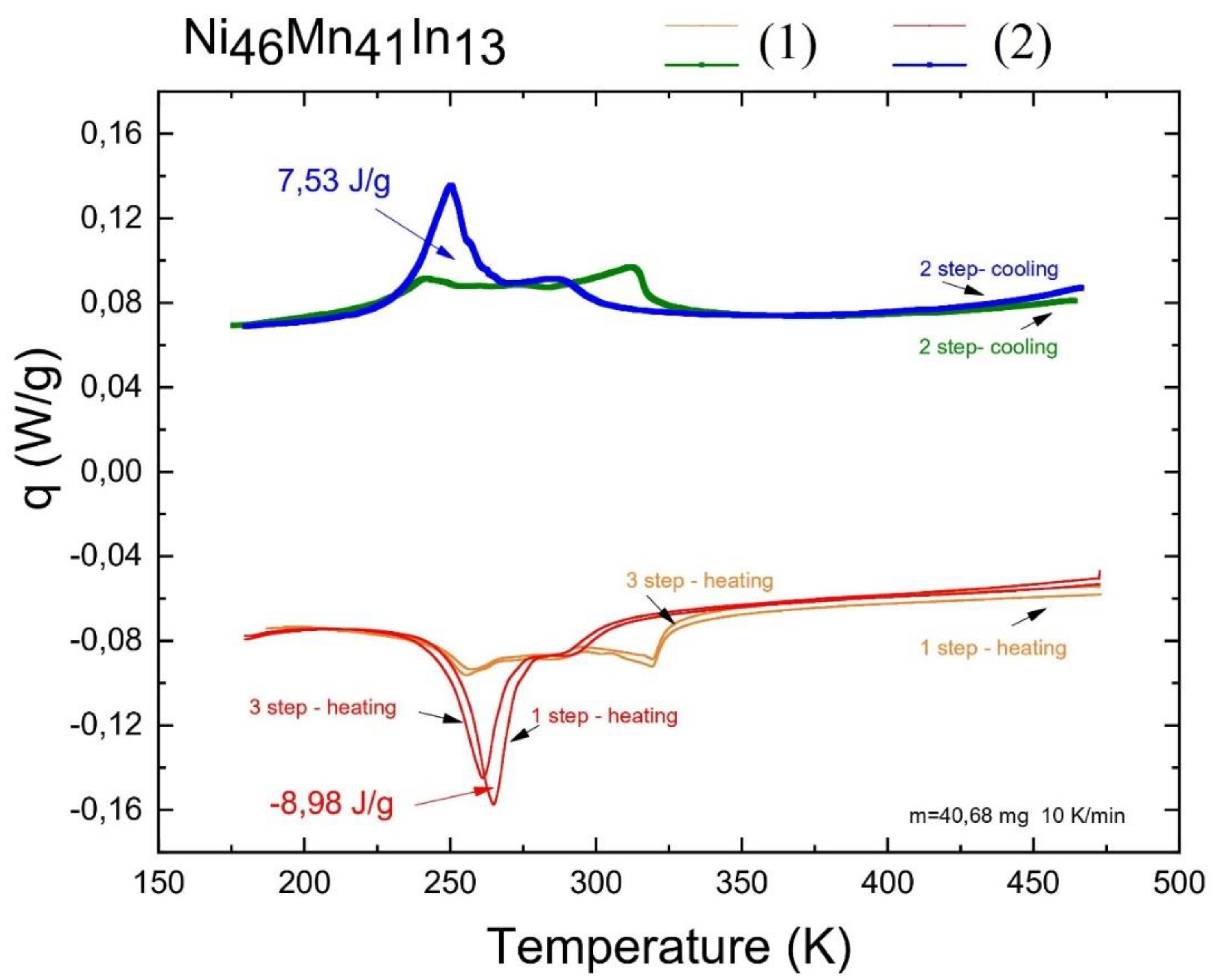
Thermal analysis determined the martensitic transformation temperatures; DSC data are presented in
Figure 1. Quenching led to an increase in the temperature of direct and reverse martensitic transformations, but did not affect the width of the hysteresis. The thermogram shows that hardening leads to a decrease in the Curie temperature and "brings together" the phase transformations of the first and second order, that is, the martensitic transformation and the Curie point, compared to a slowly cooled alloy. Moreover, the latent heat of the martensitic phase transformation in a slowly cooled alloy is approximately equal to that for the Curie point and is much less than that for the martensitic transformation of a quenched alloy. From this, it should be expected that the magnetocaloric effect for the quenched alloy as a result of martensitic transformation will be higher. For both alloys, the peaks on the thermogram are not sharp, and the martensitic transformation occurs in a wide temperature range (on the order of 20–25 K), gradually approaching the Curie point.
Table 1 presents the characteristic temperatures of direct martensitic (Ms and Mf) and reverse martensitic (As and Af) transformations, which were determined by the secant method (
Figure 1).
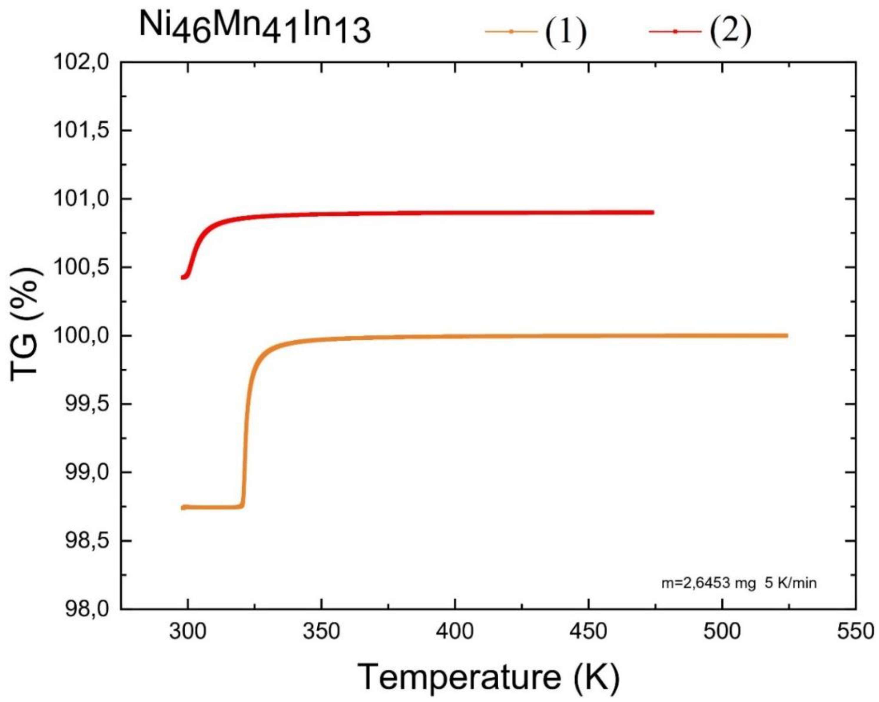
Thermogravimetric analysis specified the Curie temperature, and it was 321 K for slowly cooled and 305 K for quenched,
Figure 2.
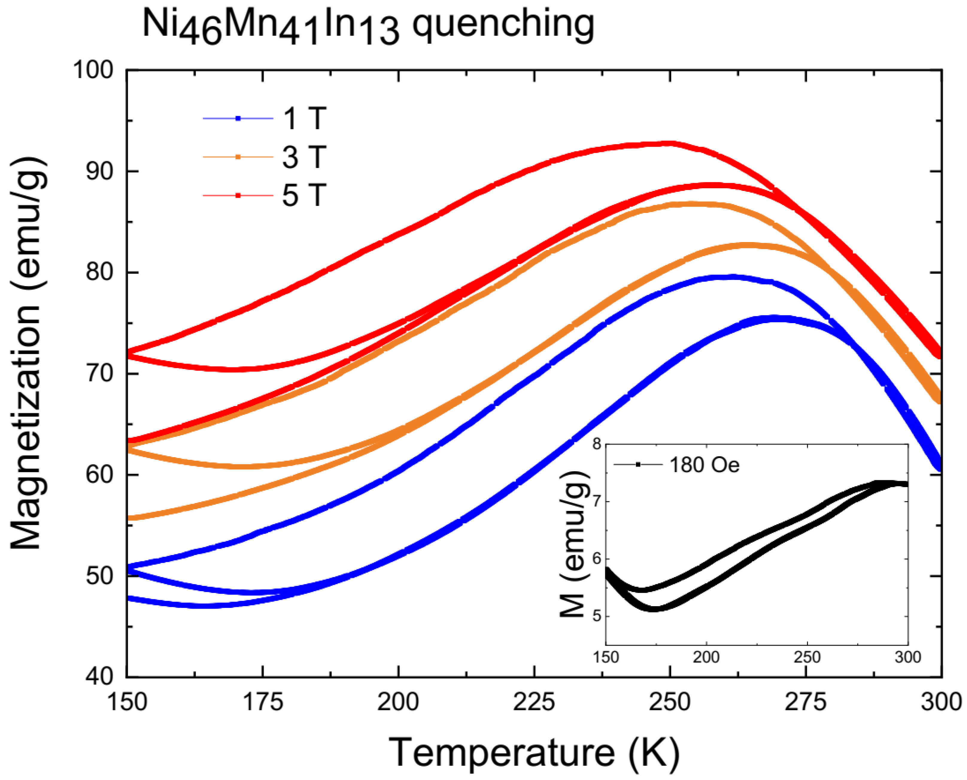
The temperature dependences of the magnetizations of a quenched microsample weighing 1.51 mg in magnetic fields of 0.01 and 1, 3 and 5 T are presented in
Figure 3. The metamagnetic structural phase transition is highly diffuse and does not complete until 170 K. The shift in the characteristic temperature Ms during magnetization is 4 K/T. It can be seen that with decreasing sample size, the temperature region of existence of the metamagnetostructural phase transition increases from the range of approximately 274-234 K to 291-167 K (
Table 1). Similar behavior is observed in thin films with a thickness of 50-150 nm. An increase in the proportion of surface energy relative to volumetric energy is qualitatively similar to stress fields that expand the region of existence of ferromagnetic austenite and thereby lower the temperature Mf to 160 K. For slowly cooled alloy see [
5].
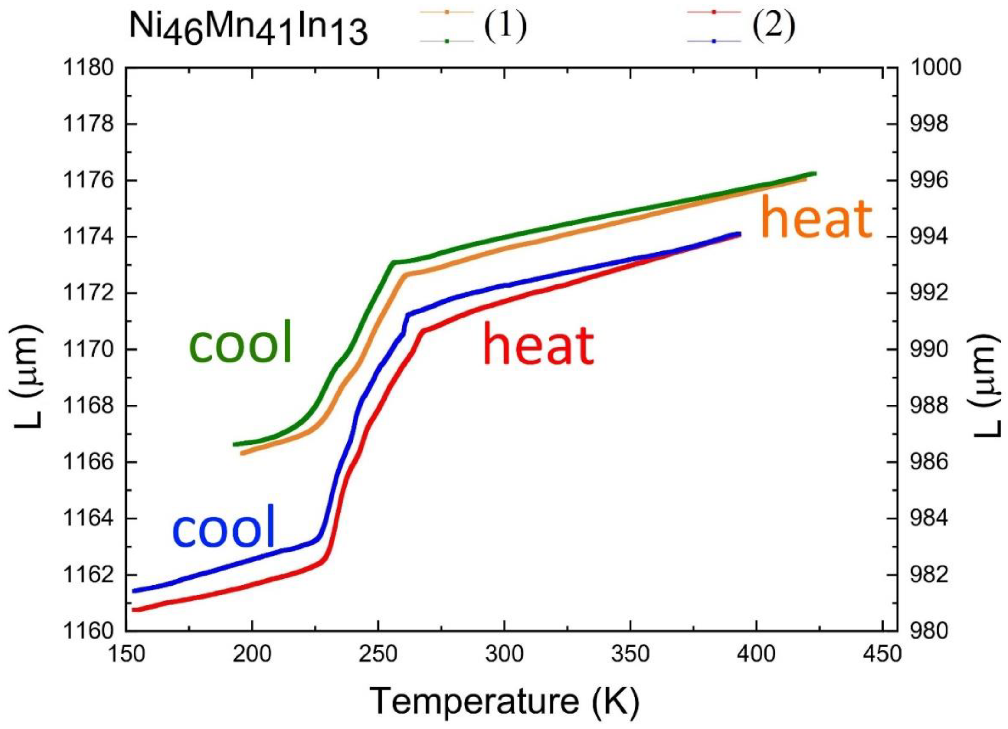
Thermomechanical analysis shows a linear change in CTE outside the region of martensitic transformations and a sharp jump as a result of martensitic transformation, hysteresis is also observed. In this case, the CTE of the hardened sample as a result of martensitic transformation is almost two times higher (
Figure 4).
On
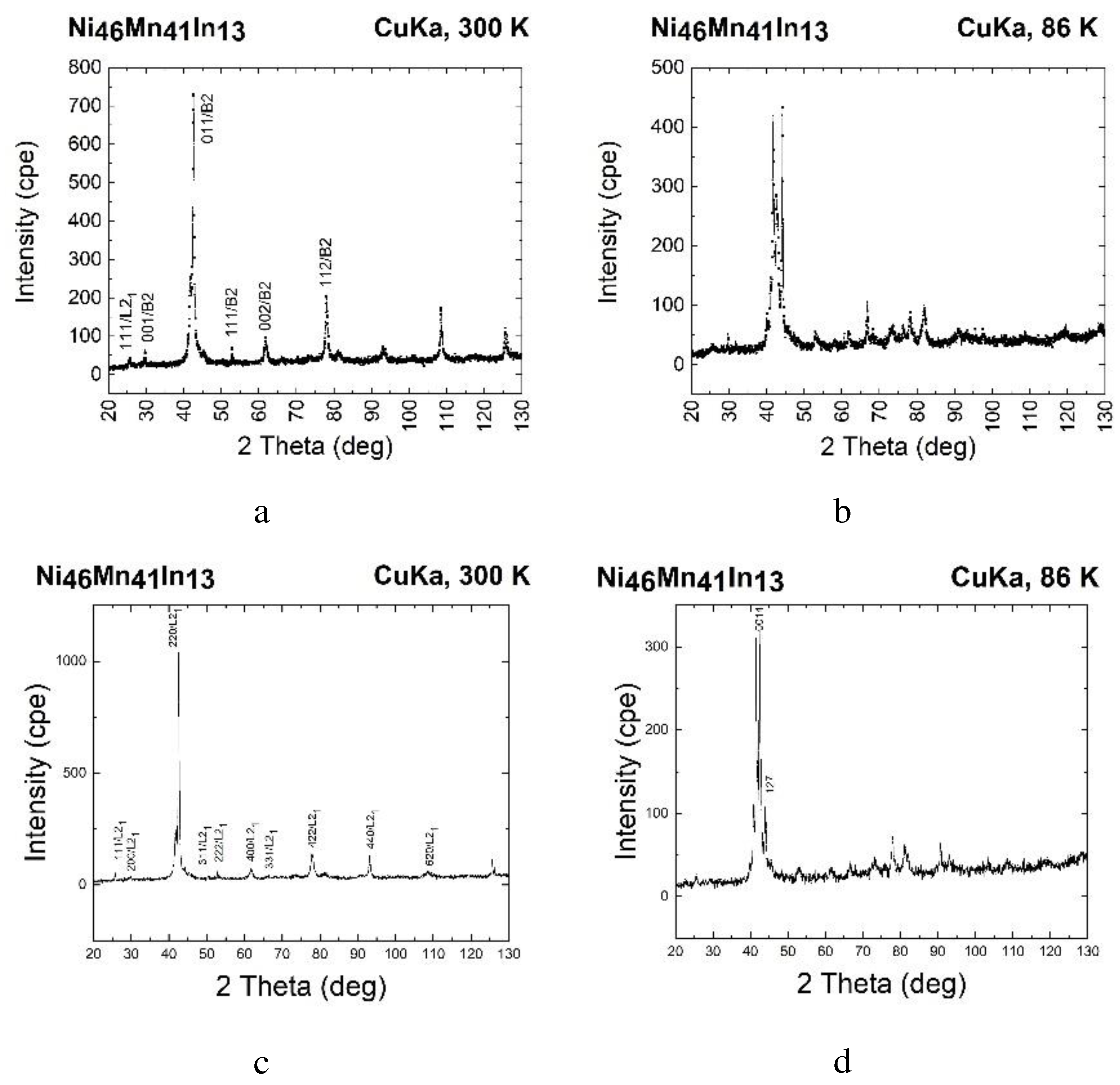
Figure 5 shows X-ray patterns of quenched (a, b) and slowly cooled (c, d) alloys under study. The space group of the crystal lattices of both alloys is Fm−3m. At room temperature, both alloys are in the austenitic state with bcc fundamental lattice reflections (220), (400), and (422) of the highly ordered phase L2
1. Since the B2→L2
1 ordering process is a diffusion process, predominantly proceeding at maximum rates at temperatures of 0.6–0.9 of the melting point, a slowly cooled sample should have a large fraction L2
1 of the ordered solid solution. Indeed, superstructural reflections (111), (311) and (331) in a slowly cooled alloy indicate that a part of the austenite is ordered according to the L2
1 type. The well-pronounced peak (111) in the X-ray diffraction pattern of the slowly cooled sample indicates a higher proportion of L2
1 than that of the quenched sample, in which the (200) L2
1/(001) B2 peak is better pronounced, and the (311) and (331) reflections are practically absent.
After cooling to 86 K, the (220) peak of the austenitic high-temperature phase disappears in both samples, and a martensitic microstructure appears in the alloys, in which the austenite peaks become very weak (in a slowly cooled alloy, they practically disappear). However, the crystal structure of these martensites is different. In [
9,
10], the parameters of the crystal lattice of 14M martensite in the Ni
47Mn
42In
11 alloy during cooling were determined using the lattice periods and angles measured by the X-ray method, and the profile of the X-ray peaks of Bragg reflections in the 2θ angles for a martensite crystal was calculated. Using these data, it is possible to index the X-ray diffraction pattern of the slowly cooled alloy as 14M martensite with a monoclinic structure. The X-ray diffraction pattern of the hardened alloy, taken at 86 K, shows a complex two-phase structure of cubic austenite and modulated martensite. Apart from reflections from austenite and martensite, no additional peaks are observed.
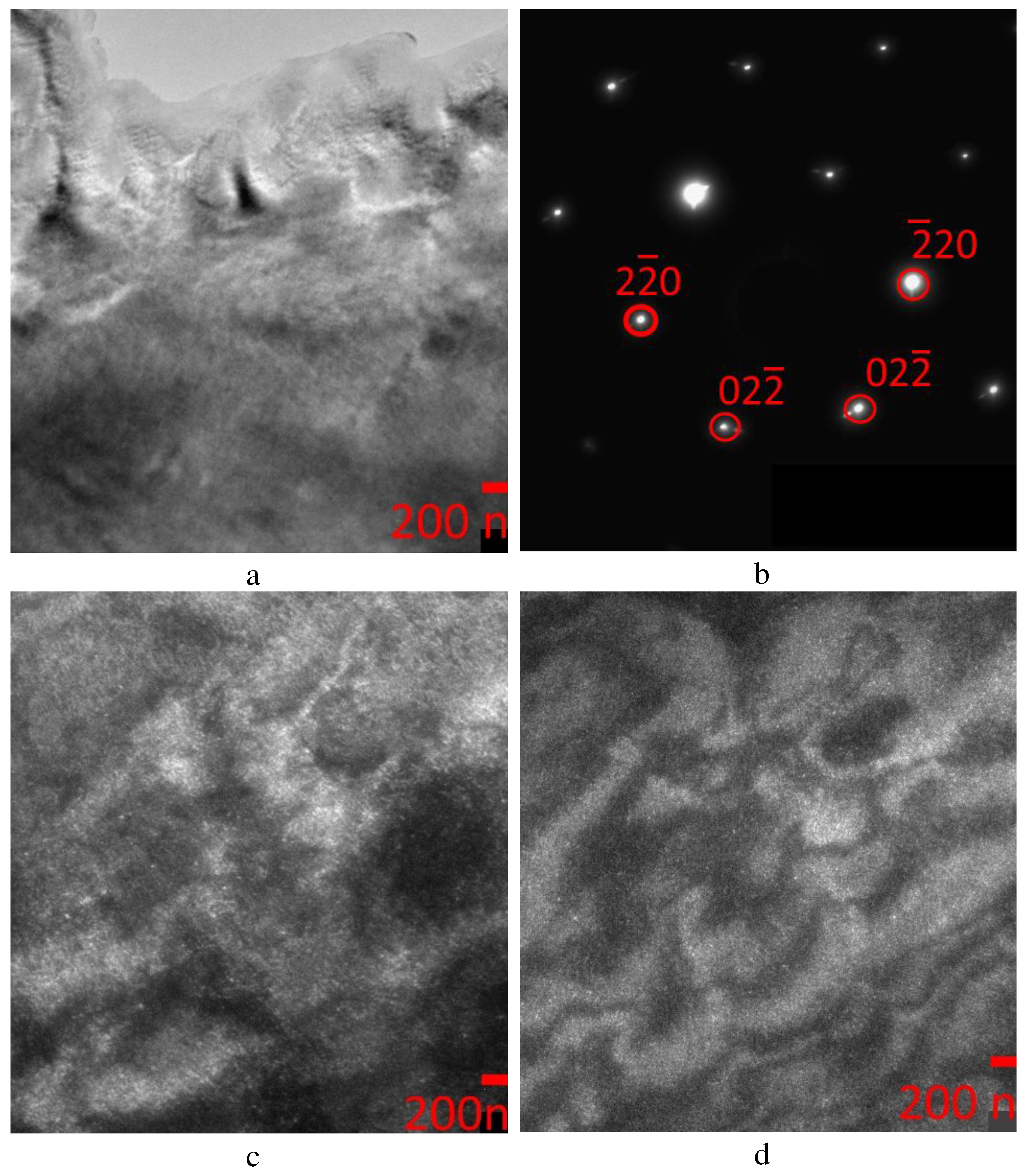
At 300 K, a tweed banded diffraction contrast was observed in bright-field images of the austenite of the quenched Ni-Mn-In alloy (
Figure 6a). Tweed contrast is accompanied by the appearance of satellites and/or diffuse scattering in diffraction patterns (
Figure 6b). The main diffraction spots (all diffraction patterns are indexed according to L2
1 ordering) belong to a cubic cell with a lattice parameter a=5.99Å. Since the L2
1 phase is an ordered Heusler phase, it can be unambiguously identified in microdiffraction patterns only with the [110] zone axis due to characteristic superlattice reflections of the 111 type, what type of austenite phase is ordered (L2
1 or B2) according to diffraction patterns is impossible, but, as indicated above, X-ray diffraction established the presence of a phase ordered according to the L2
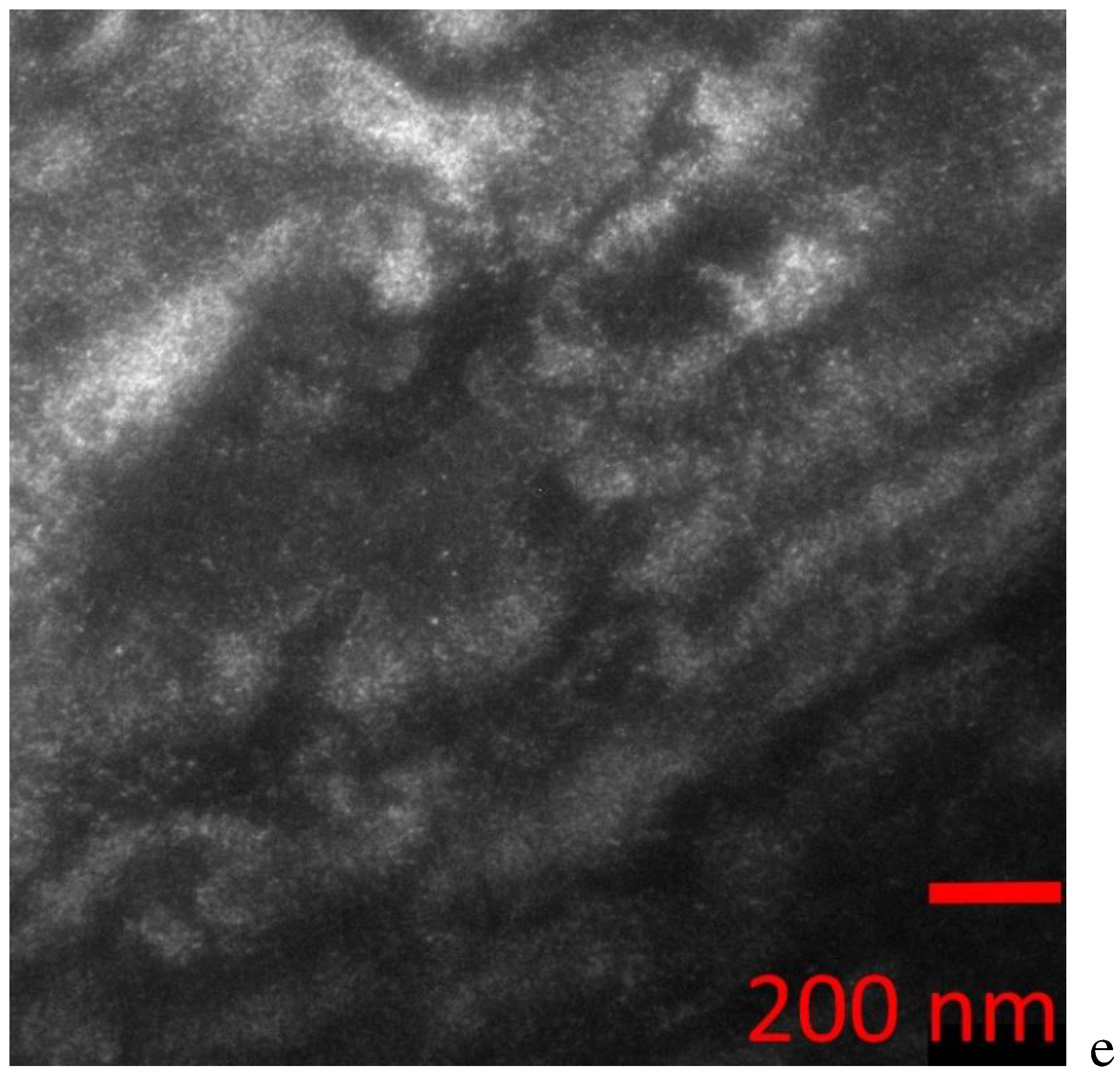
1 type. In the dark-field images shown in
Figure 6c–e, the 220-type reflections show a contrast from APBs, which are flat defects inherent only in ordered alloys, i.e., quenching did not completely suppress the B2→L2
1 ordering process.
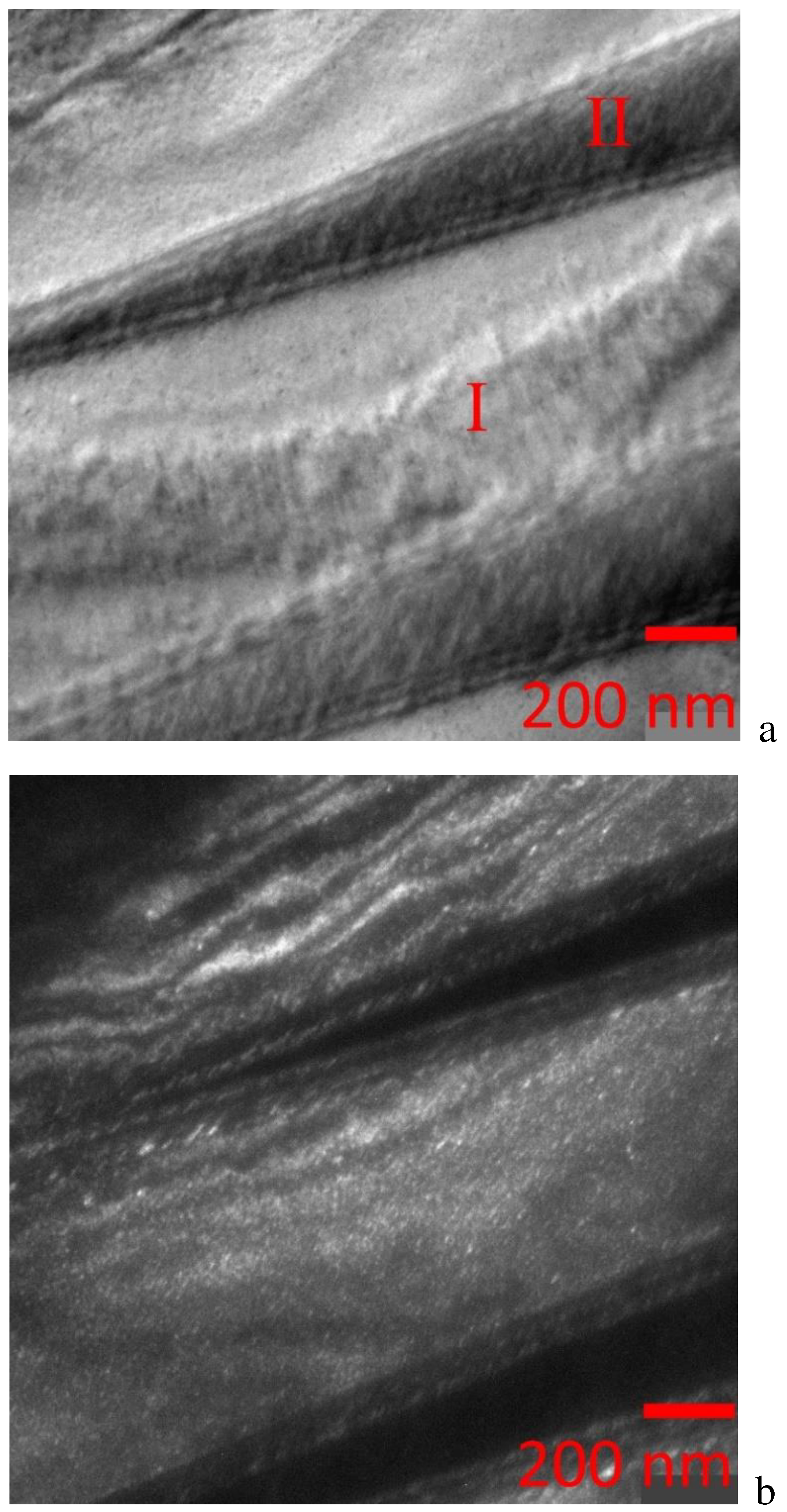
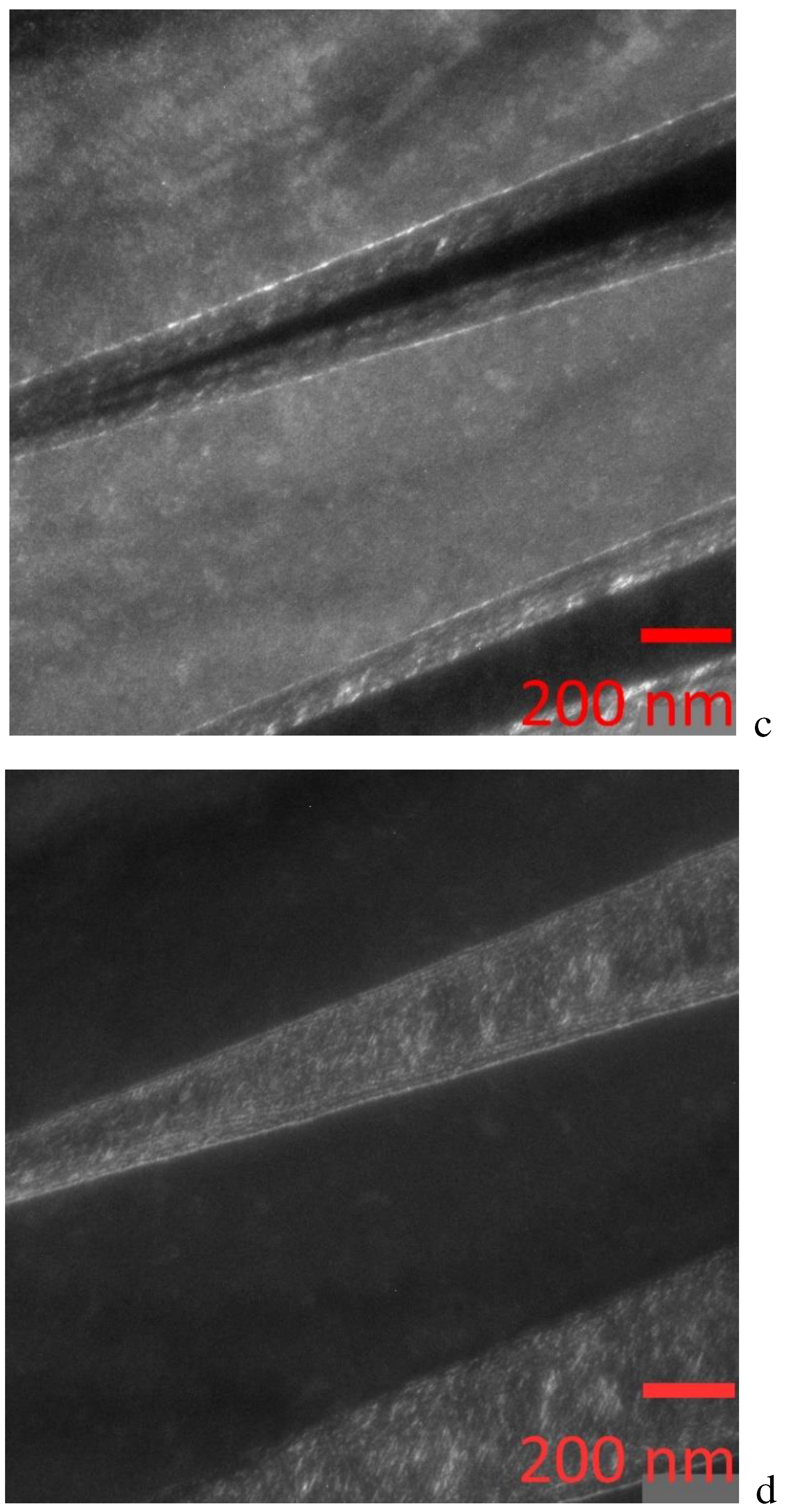
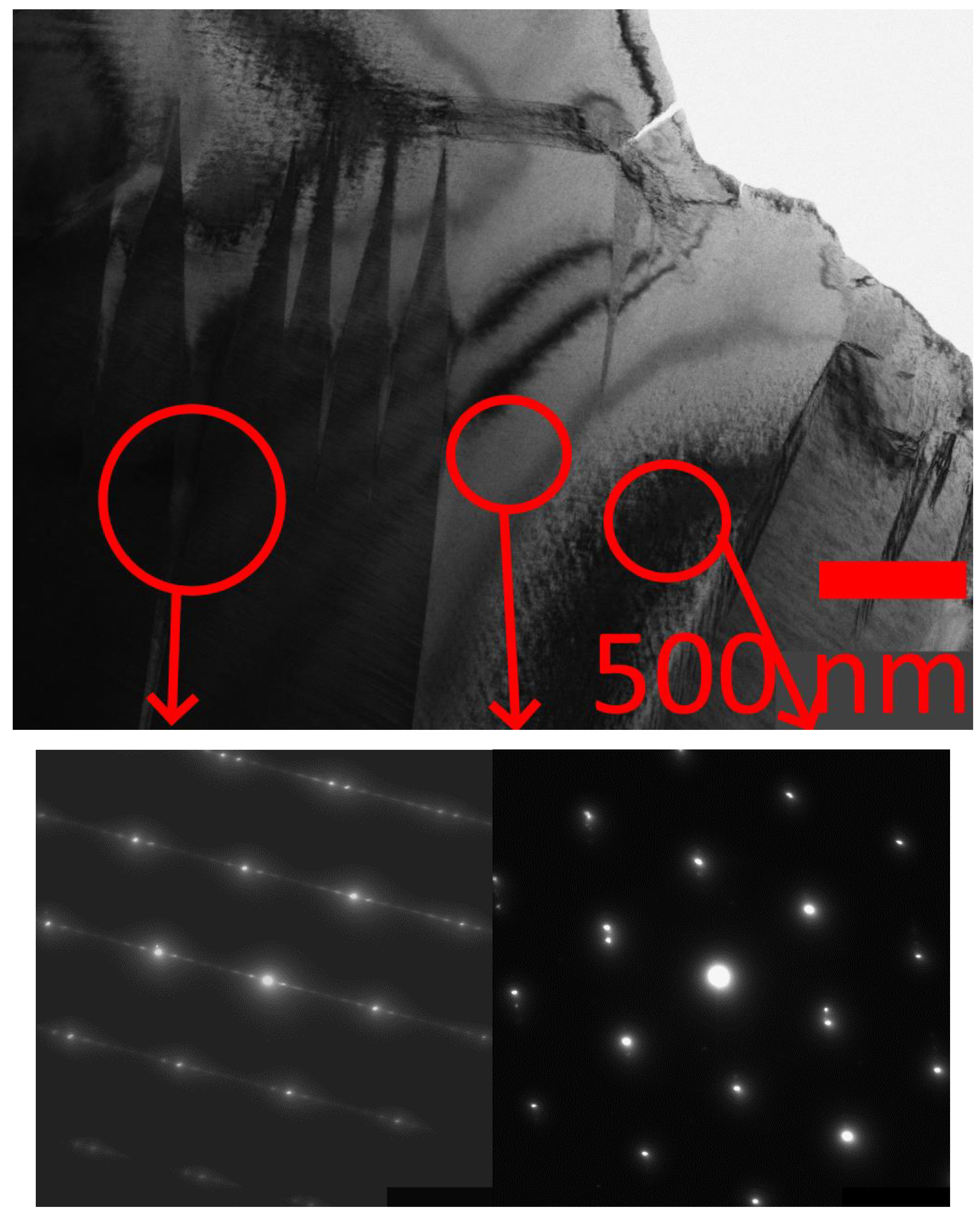
At temperatures of 120–160K, the quenched alloy is in a two-phase austenite-martensite state (
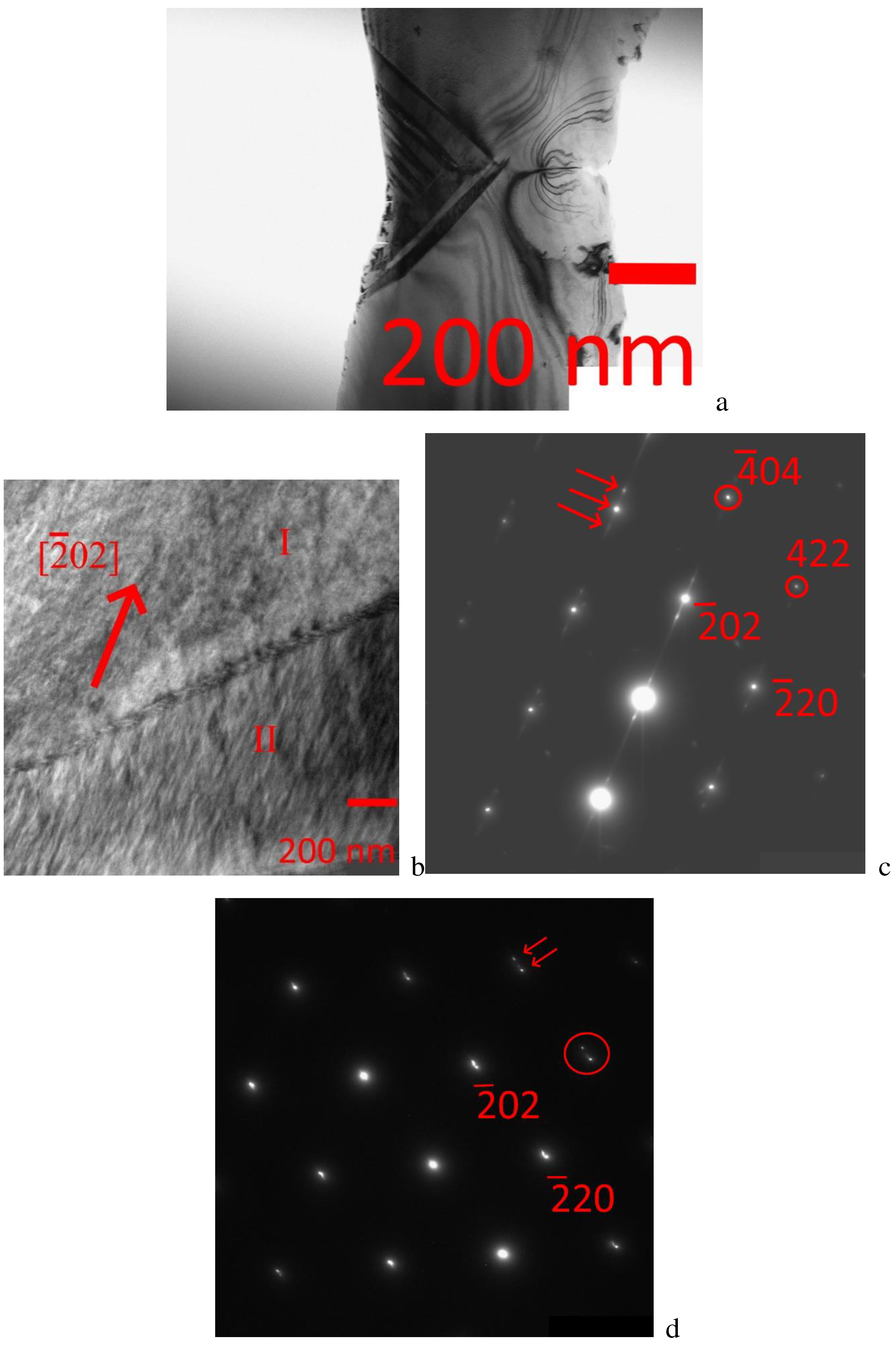
Figure 7). On
Figure 6a shows a TEM image taken at 160 K and illustrating, at first glance, the appearance of acicular martensite. On the bright-field image at a higher magnification (
Figure 7b), two regions marked I and II can be distinguished, the diffraction patterns from which are shown in
Figure 7c,d, respectively. The diffraction pattern obtained from region I (
Figure 7c) shows diffuse strands between the main reflections and extra reflections at positions 1/5<220>∗L2
1 along the <110>∗L2
1 directions (indicated by arrows). Extra reflections of this type suggest the formation of a modulated 10M martensite structure. But instead of twins, region I is characterized by a tweed contrast due to the formation of a nanodomain structure consisting of retained austenite and martensite (L2
1/B2+10M) or the observed structure corresponds to a pre-martensitic state, since there are diffuse scattering effects characteristic of such a state along the <110> directions on diffraction picture. In region II, a contrast is observed in the form of a system of bands, which can be correlated with the pre-martensitic state to the fine-twin structure of the long-period 14M martensite. One of the systems of bands is perpendicular to the direction of splitting of the main reflections when satellites appear and is parallel to one of the families of planes of the {110}L2
1 type. The far reflections have extra reflections in positions 1/7<220>∗L2
1 (
Figure 7d, indicated by arrows), which suggests the formation of a modulated 14M structure. In addition, the absence of twinning may be due to the fact that the martensitic transition is observed at a very early pre-martensitic stage, when the appearance of twins as a stress relief mechanism has not yet arisen. Thus, the analysis of diffraction patterns at temperatures of 120–160 K shows a pre-martensitic nanodomain austenite – martensitic (10M and 14M) state. Dark-field images (
Figure 8) show that in the main structural reflections belonging to the austenite phase, in the electron diffraction pattern from region I of the coexistence of austenite with 10M martensite (
Figure 8b,c), high-density APBs burn. These regions are interspersed with plates of II coexistence of austenite with 14M martensite (
Figure 8d), which burn in extra reflections corresponding to 14M martensite (extra reflections are circled in the electron diffraction pattern in
Figure 7d). The dark-field image reveals a fine streaky structure within plates II. The projection directions of the normal to the thin banded contrast are parallel to the splitting direction of the <220>∗L2
1 reflections in the microdiffraction pattern.
On dark-field images, the interface between plates I and II looks interesting – clean and even. The thickness of this region, when plates I shining, is ~100 nm, and when plates II shining, the thickness is almost three times less. Moreover, the regions overlap in dark-field images, that is, the diffraction effects related to the structure of the region belong to both plate I and plate II.
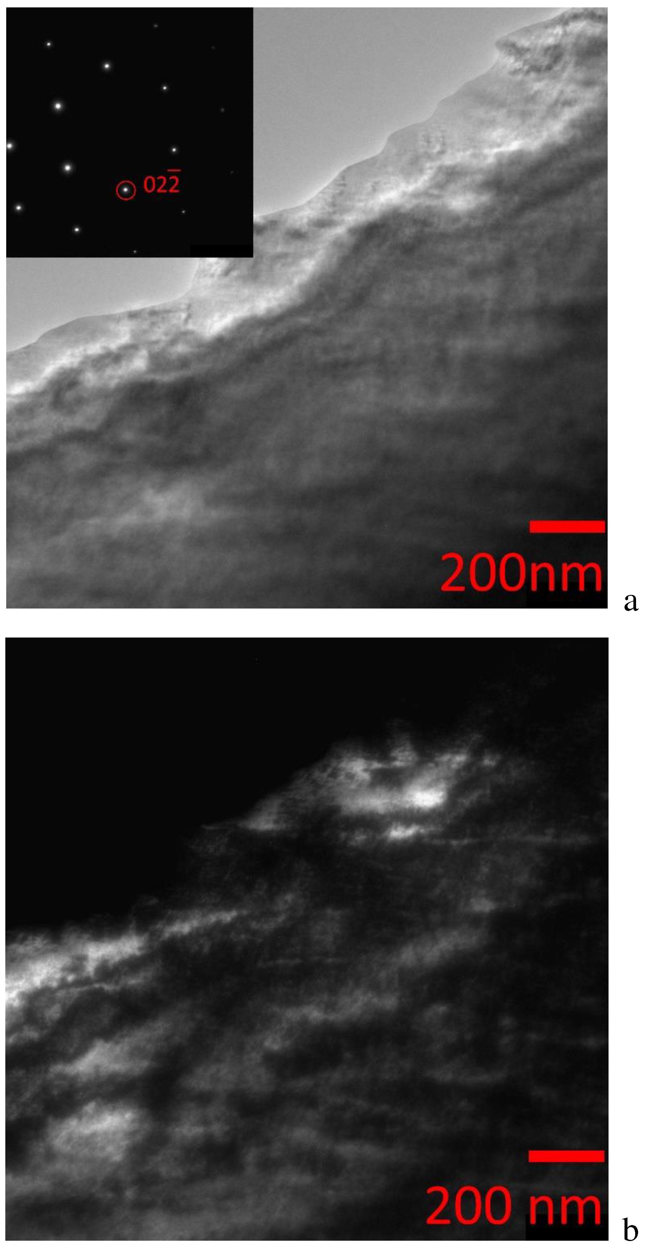
The slowly cooled alloy at room temperature has a cubic crystal lattice of austenite ordered according to the L2
1/B2 type. A tweed contrast is observed on the bright and dark field TEM images of the austenite structure of the alloy under study (
Figure 9a). At slow cooling rates from the melt, the nonstoichiometric Ni-Mn-In alloy can decompose into regions that differ both in chemical composition and in different levels of ordering, which leads to the formation of a modulated periodic austenite structure [
5]. The dark-field image (
Figure 9b) obtained in the 02–2 reflection (all diffraction patterns are also indexed according to the L2
1 ordering) shows a contrast from APBs in which the L2
1 superstructure is broken and the order of atoms is close to the B2 structure. The size of the L2
1 domains observed in the bright and dark field images is ~150 nm, i.e., much larger than in the case of the quenched alloy. Along with an increase in the domain size, the volume fraction of APB becomes smaller, which suggests that the kinetics of martensitic transformation can change with the density of APB.
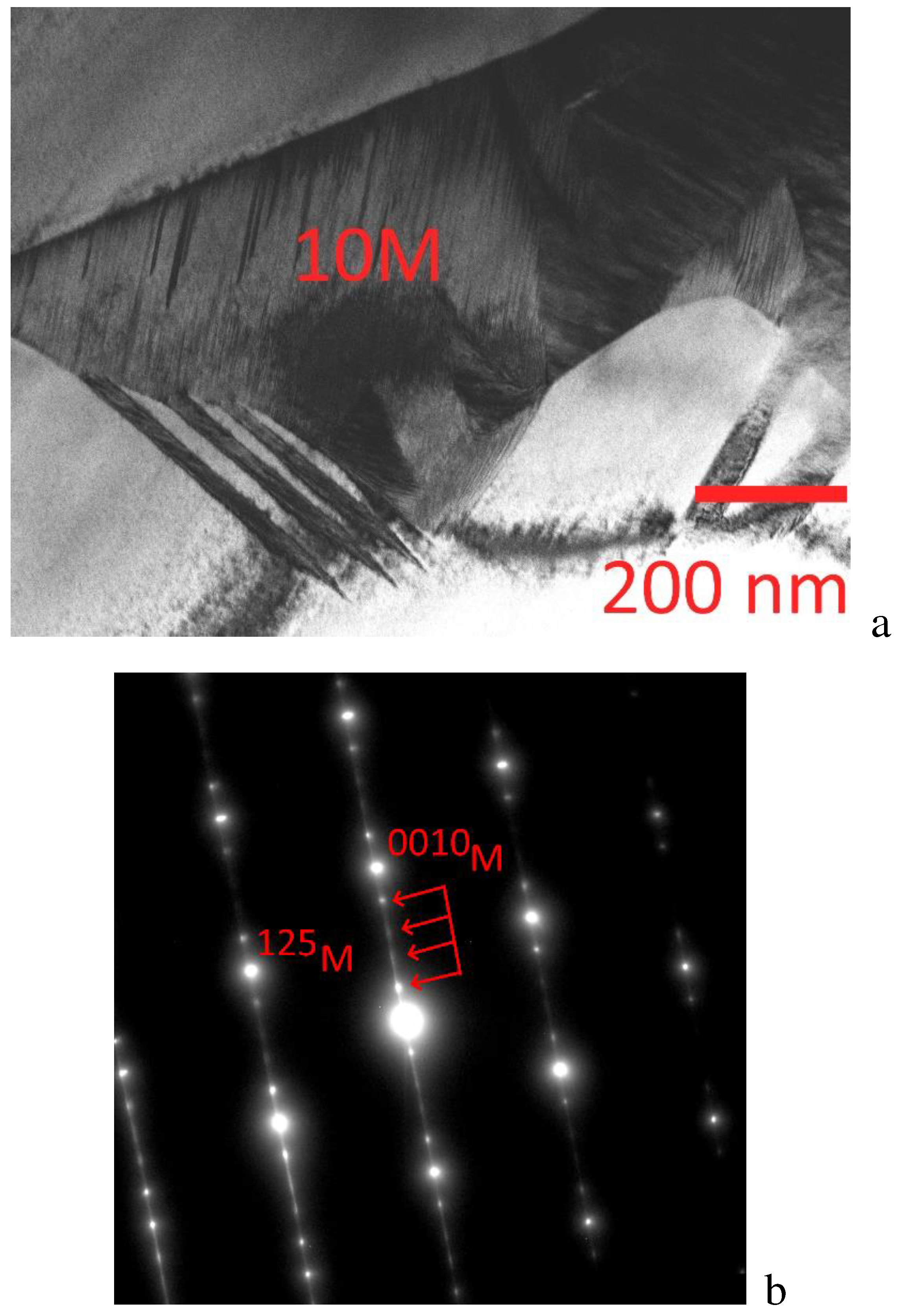
In situ cooling experiments have shown the sequence of martensite formation. In a slowly cooled alloy, when the temperature drops to 150K, the martensitic transformation proceeds with the formation of modulated martensite 10M (L2
1/B2 → 10M). On
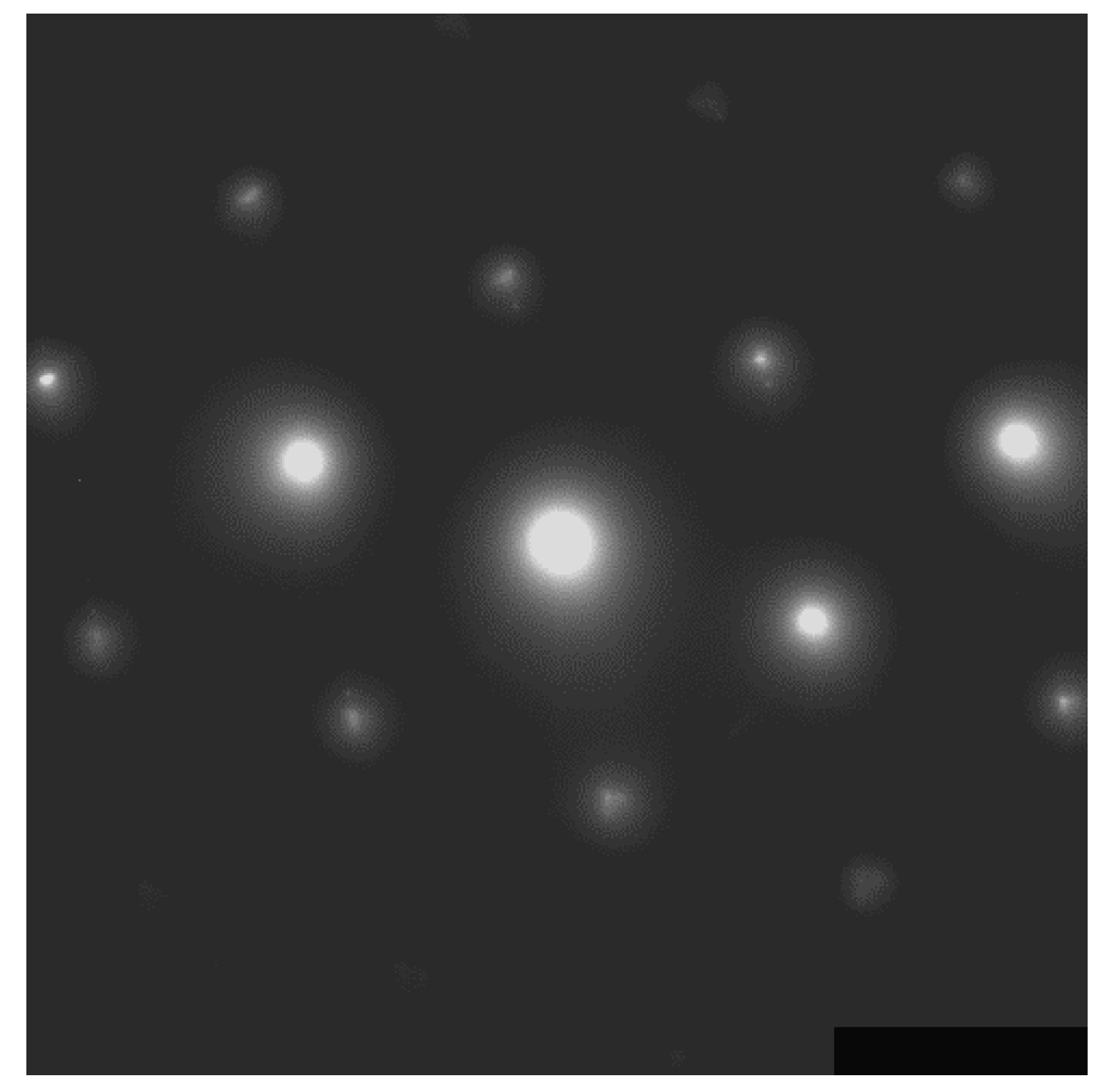
Figure 10a is a bright field image showing the microstructure within a martensite plate (in the center of the figure). The corresponding diffraction pattern (
Figure 10b) shows superstructural reflections typical of 10M martensite when two main spots are separated by four satellite spots. The fine structure of the 10M martensitic region becomes visible as a result of visualization of the contrast from many parallel stacking faults, which is a kind of additional shear to accommodate the transformation and achieve the formation of an invariant plane between austenite and martensite. The diffuse character of superstructural reflections also indicates a high stacking fault density.
An analysis of the diffraction patterns obtained from a thin foil at 120 K revealed various structures. It is possible to single out at least three different structural-phase regions shown in
Figure 11 along with the corresponding diffraction patterns. The simultaneous appearance of various structures in thin films or foils in comparison with the bulk structure is a phenomenon associated with the fact that the martensitic transformation strongly depends on size effects, i.e., on the ratio of volume and surface energies, and is completely suppressed when the plate thickness is less than 50 nm [
11]. In the area of
Figure 11 (in the thin part, right circle), there is a tweed contrast with characteristic diffuse scattering in the diffraction pattern in the form of diffuse strands (L2
1/B2). The region to the left (center circle) contains a mixture of cubic austenite and 14M martensite (L2
1/B2 + 14M). In the leftmost region deep into the foil (in the thickest part, left circle), a multilayer 14M martensite is formed, the orientation relationships between the high-temperature L2
1 phase and 14M martensite are: (001)14M ||(110)L2
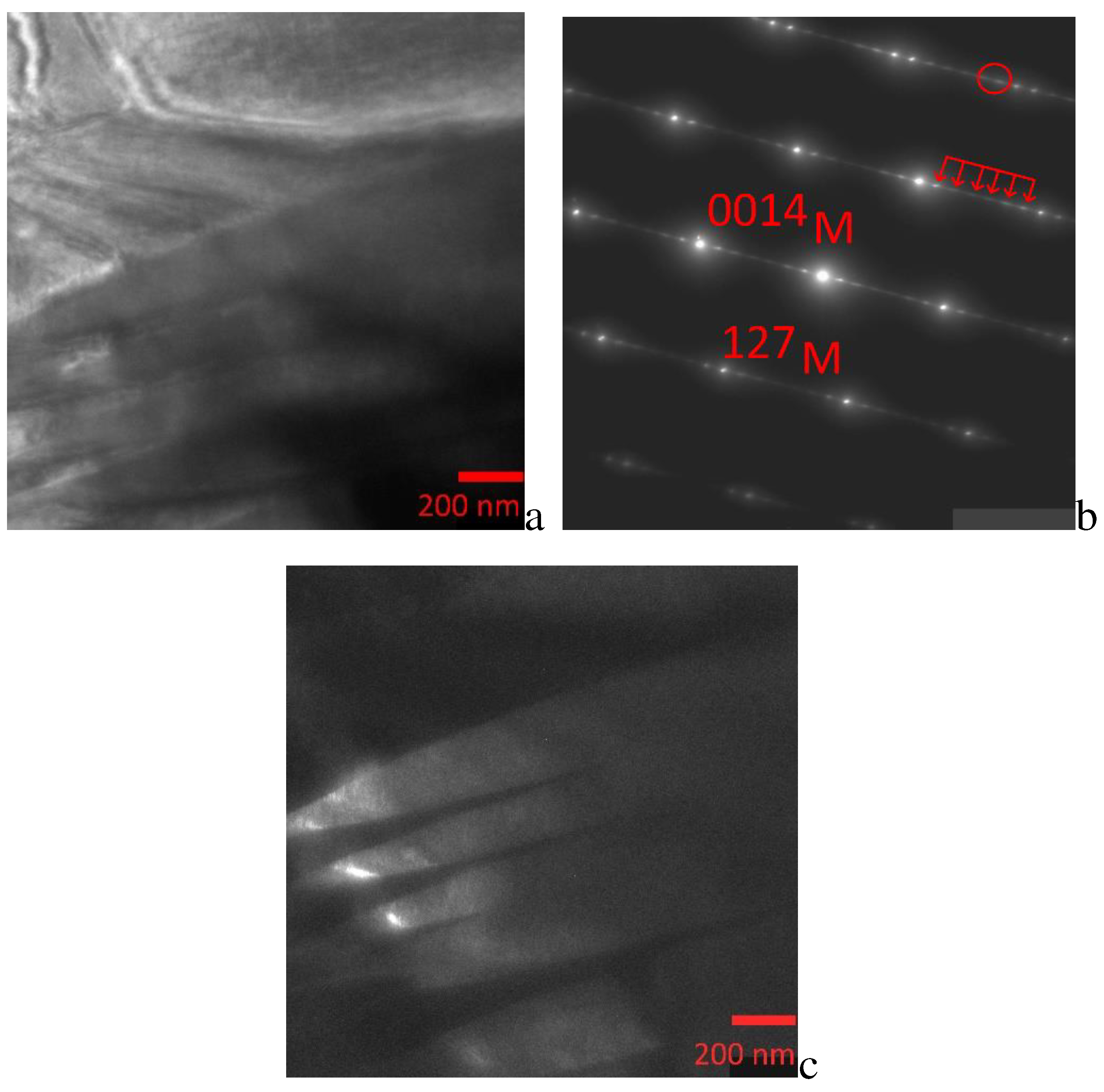
1. Lowering the in situ temperature of the slowly cooled alloy to 120 K caused the 10M martensite regions to undergo a martensitic transformation to 14M martensite. Microdiffraction patterns obtained from 14M martensite (
Figure 12) contain rows of extra reflections of the 1/7<220>∗ type along the <110>∗L2
1 directions. The dark-field image (
Figure 12c), taken in two extra reflections of the 14M crystal (marked with a circle in
Figure 12b), shows a thin banded structure inside the plates, which is not revealed in the bright-field image. The projection directions of the normal to the thin banded contrast are parallel to the [0014]M direction in the microdiffraction pattern. Thus, an initially single-phase alloy at room temperature, ordered according to the L2
1/B2 type, experiences a two-stage austenite-martensite-martensite transformation L21/B2 → 10M → 14M, since its microdiffraction patterns contain additional extra reflections of the 1/5<220>∗L2
1 type and 1/7<220>∗L2
1 (
Figure 11 and
Figure 12).
From the above data of transmission electron microscopy, it can be seen that the intermartensitic transformation 10M→14M practically does not lead to a change in the crystallographic orientation of the martensitic regions. The electron diffraction patterns obtained from 5M and 7M martensites (
Figure 10b and
Figure 12b) show only a change in the long-period modulation of the stacking of the basal planes. Therefore, these intermartensitic transformations may not be reflected in the measurements of physical properties and can be manifested only by the TEM method, which makes it interesting to study the evolution of modulated structures near the intermartensitic transition.
It is known from the literature data that the properties of Ni-Mn-In (Ga) systems and other three, four or more component systems are extremely dependent on the elemental composition. However, the reproducibility of the elemental composition is an extremely complex and basic task and one of the most important problems, even taking into account the large errors (0.1–1%) of the most common methods for its determination (EDX and WDX), which makes it difficult to use these alloys as structural and functional. A detailed study of the fine structure makes it possible to determine the necessary structural elements responsible for the manifestation of unique effects (MF, SME, MCE, etc.).
