1. Introduction
Number of physical properties of solids, expectantly those related to charge transport, are often described by so-called effective electron Hamiltonian describing the domain spanned over a small portion of the Brillouin zone in a restricted energy interval around the Fermi energy. Based on the underlying symmetry of the crystal lattice, at the specific points of the Brillouin zone, a minimal multi-band Hamiltonian can be constructed, which is sufficient to describe some single-particle and collective models of the system [1]. One of such examples is the Bernevig-Hughes-Zhang Hamiltonian [2], appearing to be sufficient to describe electron properties of number of systems mapped to it. In the case when two bands are located near the Fermi level, and other bands are sufficiently far in energy, the minimal Hamiltonian can be further reduced to the two-band effective Hamiltonian represented by a matrix. Electron bands of the two-band effective Hamiltonian have an electron-hole symmetry and, in multiple cases, they are simple enough to permit an analytical result for number of band-related calculations and obtained transport functions. Examples of systems whose electron bands are described by the two-band model are numerous, and can be easily found in all three dimensions. We mention just some notable examples like the Su–Schrieffer–Heeger model (SSH) [3] and Peierls model [4] in 1D, massless and massive 2D Dirac system [5–7], Weyl systems or multiple Weyl point systems [8–12], massless 3D Dirac [13], Mexican-hat systems [14–16], nodal-line systems [17], electron gas in a weak periodic potential [18], and so on.
In all mentioned systems, the single-particle and optical properties have been analytically derived, thus providing an insight into the underlying mechanisms and physical scales. In reality, however, many of specific properties that make the mentioned systems interesting are observed on small intrinsic energy scales no bigger then few meV around the Fermi energy. This makes it also challenging to experimentally distinguish different possible ground states from each other. For that sake, the single particle density of states (DOS) calculations are important, providing a direct information about electron bands. Those can be directly measured by, for example, measurement of DOS at the Fermi energy via Pauli paramagnetic susceptibility, or indirectly, as a part of the joint density of states approach to the inter-band conductivity [19]. Generally, the number of analytically solvable electron models is rather small, which is exactly why every case of effective Hamiltonian yielding an analytical result is important. Besides an academic value, it provides a way to observe similarities in electron properties between different models in various dimensions, by changing the parameters of the initial Hamiltonian promoted into the final result, precisely addressing the underlying mechanisms leading to them.
In this paper we define and analyse the two-band effective Hamiltonian capable of describing two different electronic ground states (phases). The first one is the nodal-loop phase (NLP) and it is characterised by the touching of the valence bands over a ring. The second one is the gapped phase (GP) characterised by separation of the valence bands by a finite energy gap. We find the corresponding electron dispersions for both phases and assume that the doping procedure (Fermi energy shifting) leaves the valence bands intact. We analyse the Fermi surface (FS) for each phase together with the identification of the van Hove points. Electron dispersions are presented in terms of dimensionless variables in which their properties are determined by a single parameter . It is shown that the NLP has a torus-like FS which, depending on parameter , can be doughnut-like or self-intersecting spindle, while the FS in the case of GP has trivial shape related to usual doped 3D insulators. The DOS calculations are performed by finding the corresponding integration boundaries for each phase. Finally the expressions for DOS in both phases are given. DOS of the both phases is analysed in detail, with particular emphasis on the behaviour near van Hove points and in connection to the parameter , where DOS in the NLP showed a richer structure compared to the GP. It is our intention to use the two-band model in order to shed additional light upon otherwise complicated band structures that is inherent to majority of the nodal-line systems [20,21].
2. The two-band Hamiltonian
The low-energy Hamiltonian of the 3D system under consideration, in the basis of the plane waves characterized by the wave vector
, presented as a real
matrix, reads
In the above expression,
and
are the Pauli matrices, while
,
b and
c are positive parameters. Index
is the phase index with
denoting the NLP and
denoting the GP. Hamiltonian (
1) contains square of the total Bloch wave vector
. The diagonalization of Equation (
1) is straightforward, yielding an electron-hole symmetric eigenvalues for each phase
,
We scale electron dispersion Equation (
2) to the gap parameter
, introducing dimensionless variables
,
(i.e.
) and parameter
. We obtain the dispersions Equation (
2) in dimensionless form
determined by two parameters: (1) the phase parameter
essentially controlling the band topology, and (2) parameter
that controls physical properties of bands, such as van Hove points, effective mass parameters etc. Below we provide a detailed description of band properties.
3. Valence bands and Fermi surface
Here we investigate properties of electron dispersions Equation (
3) and the Fermi surface in a doped system. Initially we assume that both phases are undoped, i.e. that the Fermi level is located between the bands. The doping procedure consists of filling the conduction band
up to some finite value of Fermi energy
(in units of
). Analytical analysis of the dispersion relation leads to the
-dependent polynomial in
,
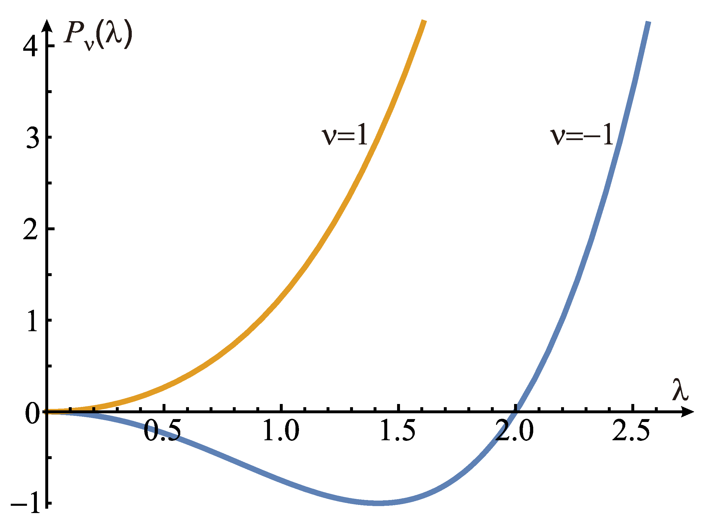
appearing to be important for further calculations and description of the spectral properties as well as the DOS (it is shown in
Figure 1). For
(NLP),
is non-monotonic function, i.e.
for
, with minimum at
, while for
(GP),
is positive monotonic function.
3.1. The nodal-loop phase (NLP)
This phase appears for
. In the intrinsic case, when the Fermi energy
, the main property of the NLP is presence of the nodal ring of radius
located in the
plane along the touching line of two bands (
3). If
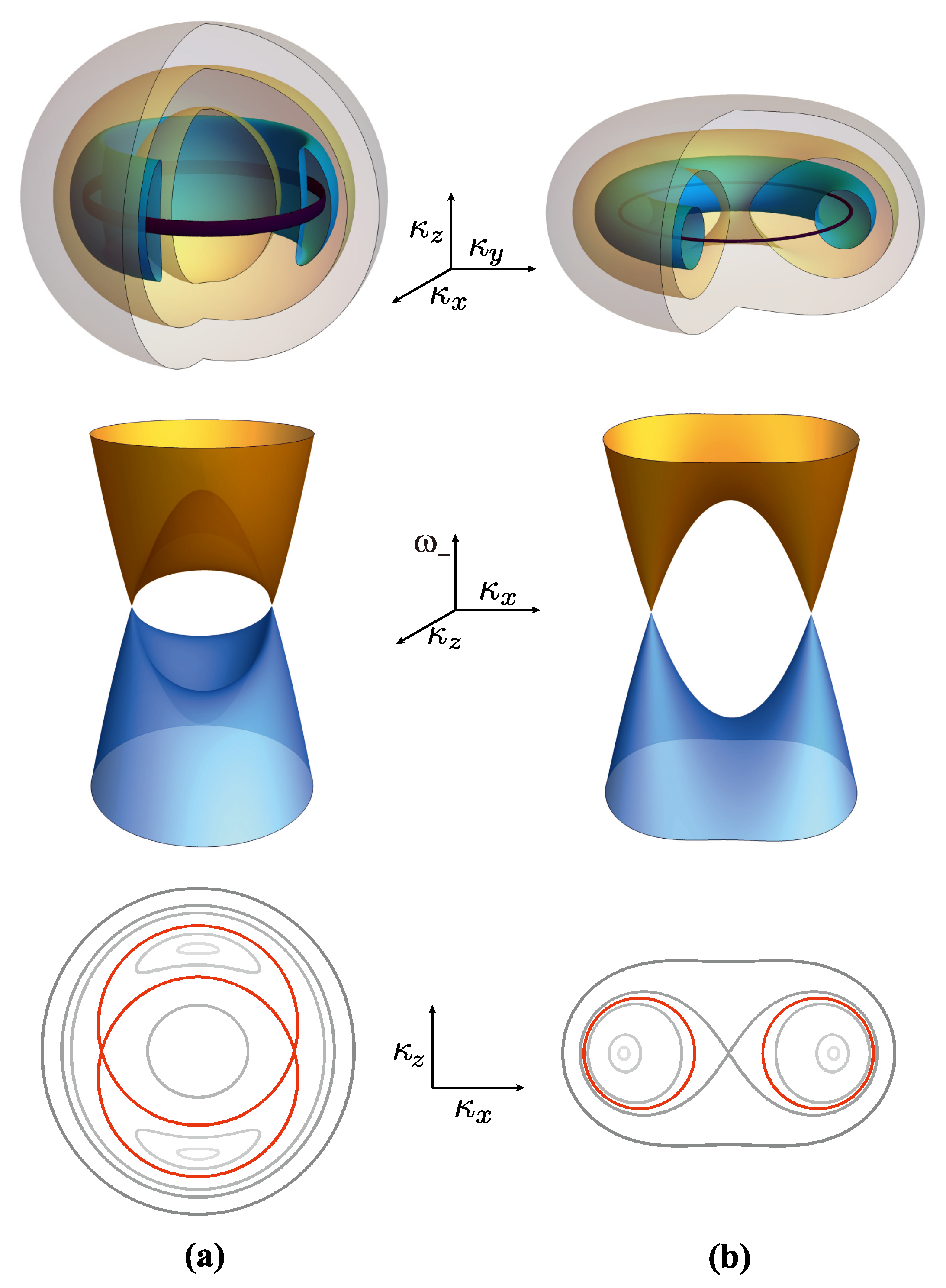
is increased, a doughnut-like Fermi surface emerges (see
Figure 2). Exact properties of this Fermi surface depend on the value of parameter
. There are two cases to be closely examined:
- a)
Case
: The Fermi surface is shown in
Figure 2a. As the Fermi energy
increases from zero, the point-like (the nodal point) cross-section, along the
, or
plane, evolves to two crescent shapes. As
further increases, the crescent shapes are inflated and eventually touch each other, forming two self-intersecting circles. The FS at this particular Fermi energy
is a type of torus called the self-intersecting spindle. The energy
at which it occurs is the van Hove saddle point. The radius of each self-intersecting circles is
while their centers are displaced by
apart. For such a torus, it is evident that
. As
increases further, the FS becomes composed of two ellipsoid-like surfaces (smaller one centered inside the bigger one) one decreasing and other increasing in size until
is reached. At
, there appears an elliptic van Hove point, at which the FS is a single ellipsoid-like surface. In the special case
, the two bands touch over a sphere of radius
. Then, if the Fermi energy is
, the FS comprises of two concentric spheres and, if
, the FS is a single sphere.
- b)
Case
: The Fermi surface is shown in
Figure 2b. As
increases, the thickens of the "doughnut" reaches a special value when its cross-section with a plane
, or
are two circles, i.e. the FS becomes a torus. As in previous case, this happens at the particular value of Fermi energy,
. In this case the FS forms a standard torus with radius of the circular cross-section
and radius from the center of the torus to the center of the cross-section
. As
is increased with respect to
, two circles of the cross-section inflate, deform and touch each other at
. This point is the van Hove saddle point, which is responsible for the kink in DOS of the 3D system as we shall show later. As
is further increased, the FS attains an ellipsoidal-like shape.
- c)
Case : The Fermi surface shows no distinctive, or interesting features other than compact doughnut-like shape. We do not show it graphically.
3.2. The gapped phase (GP)
This phase appears for
. Dominated by the band gap parameter
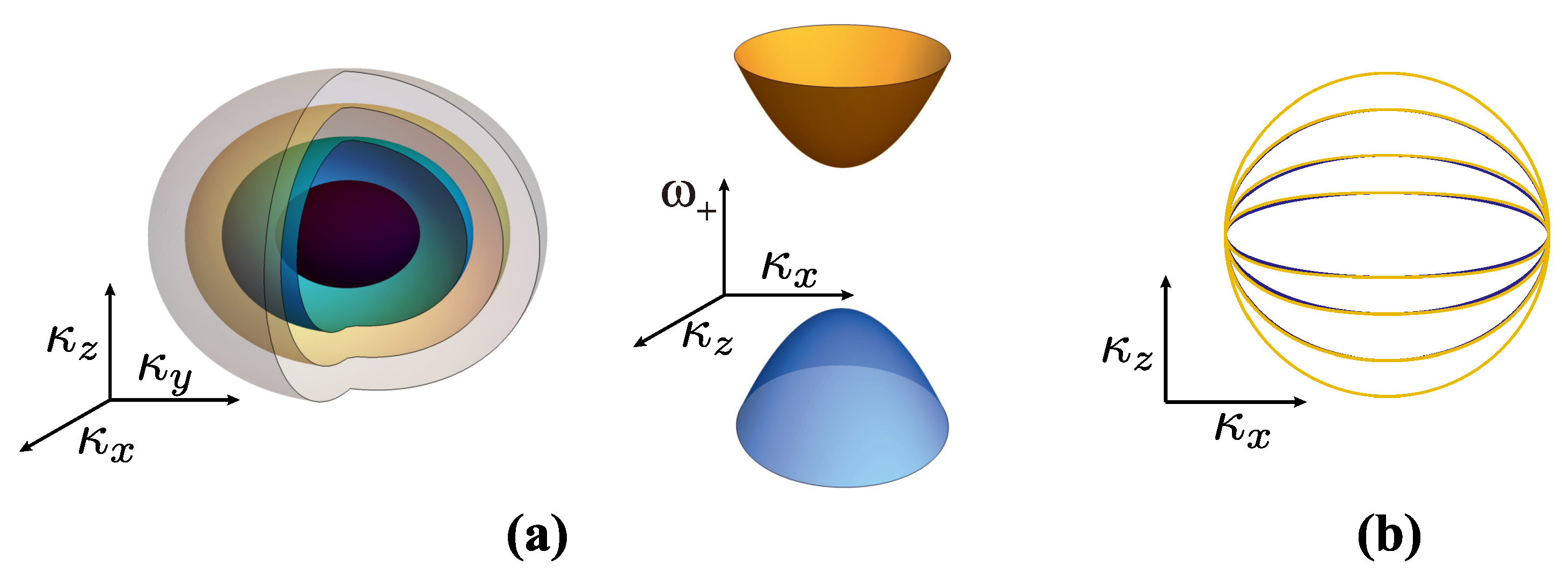
, the FS of a doped gapped phase becomes a simple ellipsoid-like structure existing only for
(see
Figure 3a), in which parameter
increases the axial anisotropy, i.e. the larger is
, the flatter is the ellipsoid (see
Figure 3b). In fact, it can be shown that the FS can be, to an excellent approximation, written in terms of the reduced ellipsoid equation with the coefficients depending on the Fermi energy
(measured from the middle of the band gap) and parameter
,
Comparison of
or
plane cross section of (
3) and (
5) for various
and
is shown in
Figure 3b. In the special case
, Equations (
3) and (
5) reduce to equation for sphere with radius
.
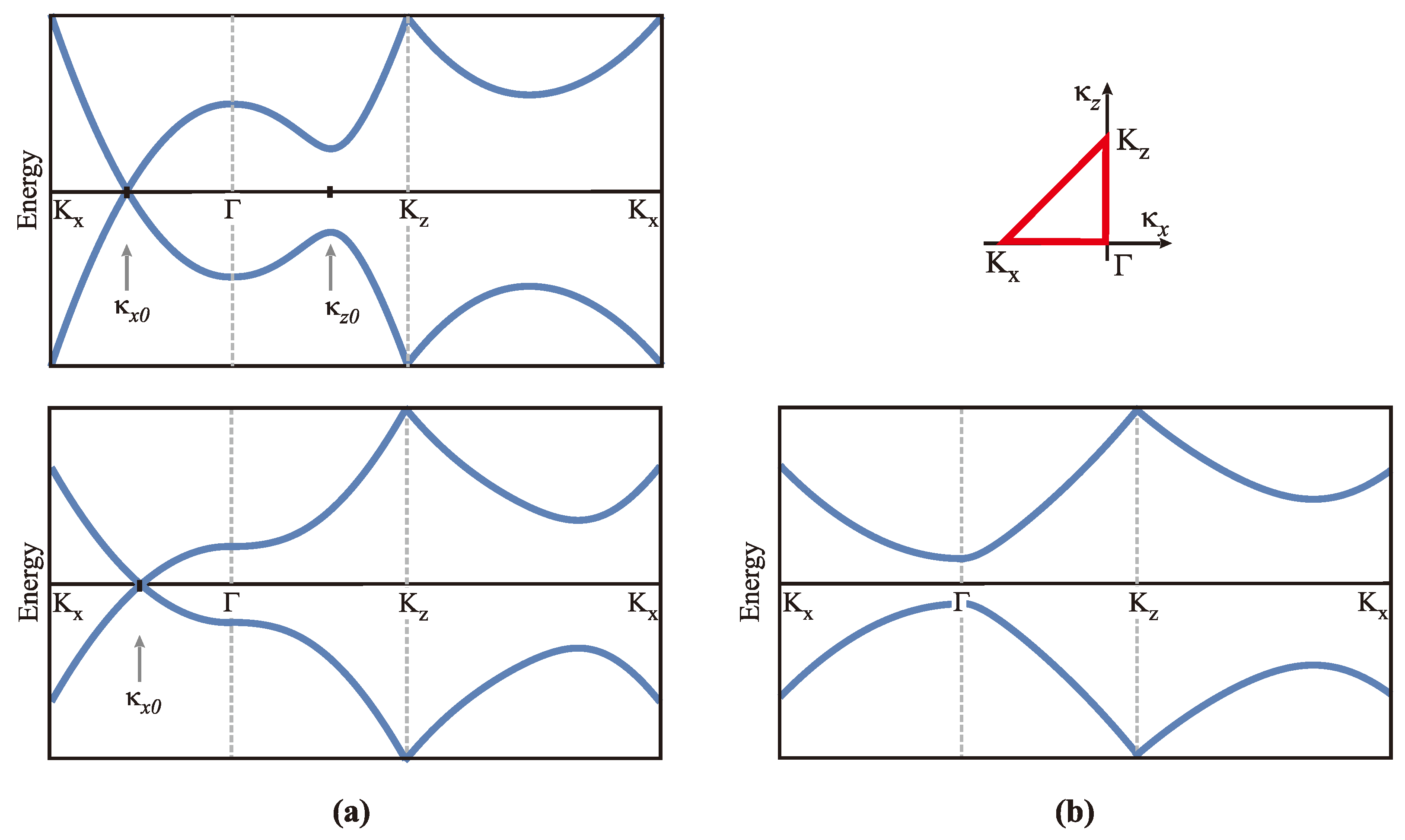
Electron bands (
3) in both, NLP and GP phases are shown in
Figure 4.
4. Density of states
Here we present calculation of the density of states (DOS) for the energy dispersion from Equation (
2) for both NLP and GP. Due to the electron-hole symmetry we use only the upper band
in the calculations. By definition, the DOS per unit volume of a spin degenerate band is [22]
To simplify further calculation we use the dimensionless variables defined in
Section 2 and, changing the sum in Equation (
6) to an integral in spherical coordinate system, we get
To further evaluate (
7) we decompose the
-function with respect to the
variable into a sum
where
are the two zero-points of the argument of the
-function with respect to variable
,
Using the identities Equations (
9) and (
8) with Equation (
7), with substitution
, we obtain
The interval of u-integration is determined by three restrictions which are enumerated here:
- ①
(the trivial restriction),
- ②
positive expression under the square root in denominator in (
10):
,
- ③
domain restriction in (
9):
implying
.
By common intersection of these three conditions, the intervals of integration are found, which depend on phase , on energy and parameter . From here on we investigate the DOS for every electronic phase separatelly.
5. Density of states in the nodal-loop phase
We set in the mentioned restrictions to find the permitted value of u. Thus we get:
- ①
,
- ②
,
- ③
.
In the above conditions we have introduced an auxiliary function
defined as
where, again,
is given by (
4). The final condition for the interval of
u-integration is found by taking the intersection
. The boundaries in
and
depend on
and
and, for specific values of those two parameters, they will shift relatively to each other giving the different intersection. It is shown, after rather tedious calculation, that, depending on value of parameter
, the interval of allowed values of
u falls in two classes:
where we have used
from
Section 3. The integration boundaries in integral (
10) are determined by expressions (12), while the primitive function is of the form
Applying the above, frequently using the identity
we finally obtain the result
where the constant factor is
The constraints on
and
in (12) appear in terms of the Heaviside
-functions in Equation (15). Also notice that, for
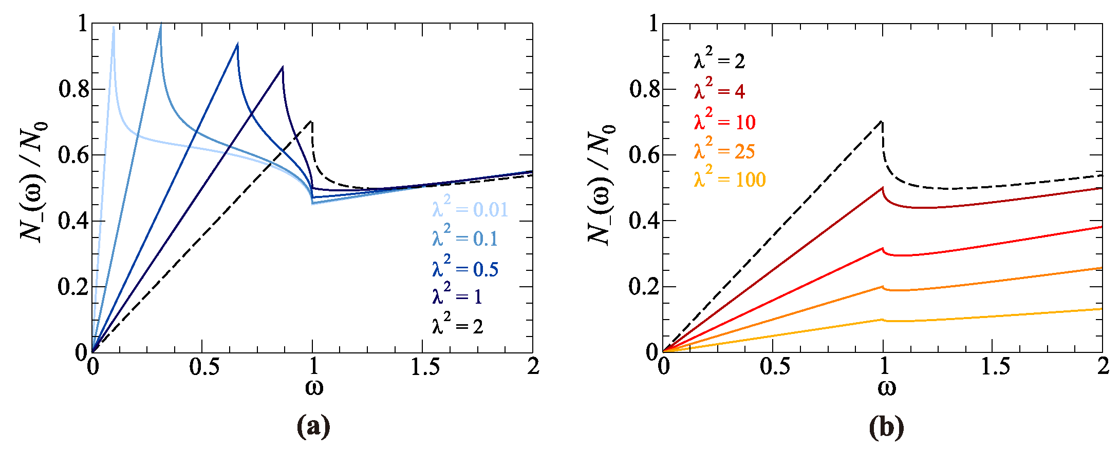
, the third contribution vanishes. The DOS (15) is shown in
Figure 5 as a function of
for several values of parameter
.
Also, in the vicinity of high symmetry points, we expand Equation (15) using the approximative Taylor expansion for
,
First, we analyse the intersecting spindle case, for
(
Figure 5a). The
function is linear in
from
up to
where the van Hove singularity, due to presence of the saddle point in spectrum, is located. The DOS at this point is
while, for
just above
, Equation (15) can be expanded to
For
, DOS monotonically decreases until the next van Hove singularity, due to presence of the elliptic point in spectrum at
, is reached. Since
is a limiting point that divides two-surfaced and a single-surfaced FS, we inspect in detail the corresponding DOS. Inserting
in Equation (15) we obtain
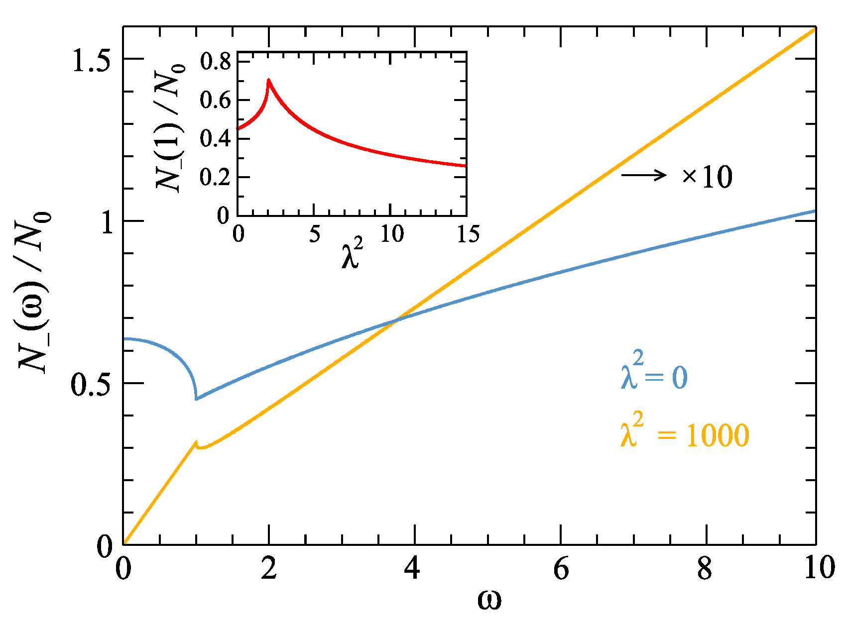
Equation (19) is shown in
Figure 6 (inset). For
it increases as function of
forming a cusp for
, after which it decreases as
.
In the high-energy limit,
, only the first two terms in Equation (15) remain. Expanding
, and using the expansion (17), we obtain
Equation (20) is similar to DOS of the 3D free electron gas. This result is to be expected since, for large wave vectors (i.e. the large energy), the dispersion (
3) becomes roughly parabolic in wave vector since the
term dominates over the
term.
Some results, found for DOS in the case of intersecting torus, apply for the "doughnut torus" case,
. The third term in the Equation (15) vanishes, and what remains is DOS linear in
, i.e.
, for
. For
, DOS has a discontinuity as shown by Equation (19), and, just above
, it has a square root dependence,
which diverges for
and therefore signals that additional elements have to be retained in the expansion of
. Thus, for
, the result up to the leading order in
is
where it is worth noticing the analytical property that DOS depends on the forth root of energy, appearing only in this case. Finally, in the high-energy limit,
follows the square root dependence given by Equation (20).
We also single out two specific cases:
1. The first one is for energy
that satisfies inequality
&
. It is shown in
Figure 6, the
case. In this interval, the auxiliary function
, so the Equation (15) reduces to
DOS in this case is linear in
, with different slopes below and above
, and highly reduced in amplitude. This property of linearity, especially in the
case, is particularly noticeable for small parameter
in Equation (
2) if other bands are much higher (lower) in energy compared to
. In this limit, this 3D system effectively resembles to the 2D behaviour (see results for DOS in Ref. [24]).
2. The second specific case is for
. It is a case when Hamiltonian (
1) is given only by the first term featuring the
Pauli matrix. Diagonalisation leads to energies [15]
Although trivial in appearance, dispersion (24) leads to the unique properties of the corresponding DOS. To see them, we analyse Equation (15) in which the third term can be written as
Setting the
in the above expression and using expansion (17) together with Equation (20) in which
we obtain [15]
This special form of DOS is shown in
Figure 6 with the dome-like feature for
below 1. This can be seen as a natural limit of the trend shown in
Figure 5 as
is decreasing.
6. Density of states in the gapped phase
Here we investigate DOS of the gapped phase by setting
in the restrictions enumerated in
Section 4, obtaining permitted intervals of
u-integration for each case:
- ①
,
- ②
,
- ③
.
In the conditions above, an auxiliary function (
11) is implemented and the intersection
determines the integration boundaries. We remind that in the GP,
(i.e. the band is located above the band gap), which makes the integration boundaries easy to determine:
Inserting the integration boundaries (27) in (
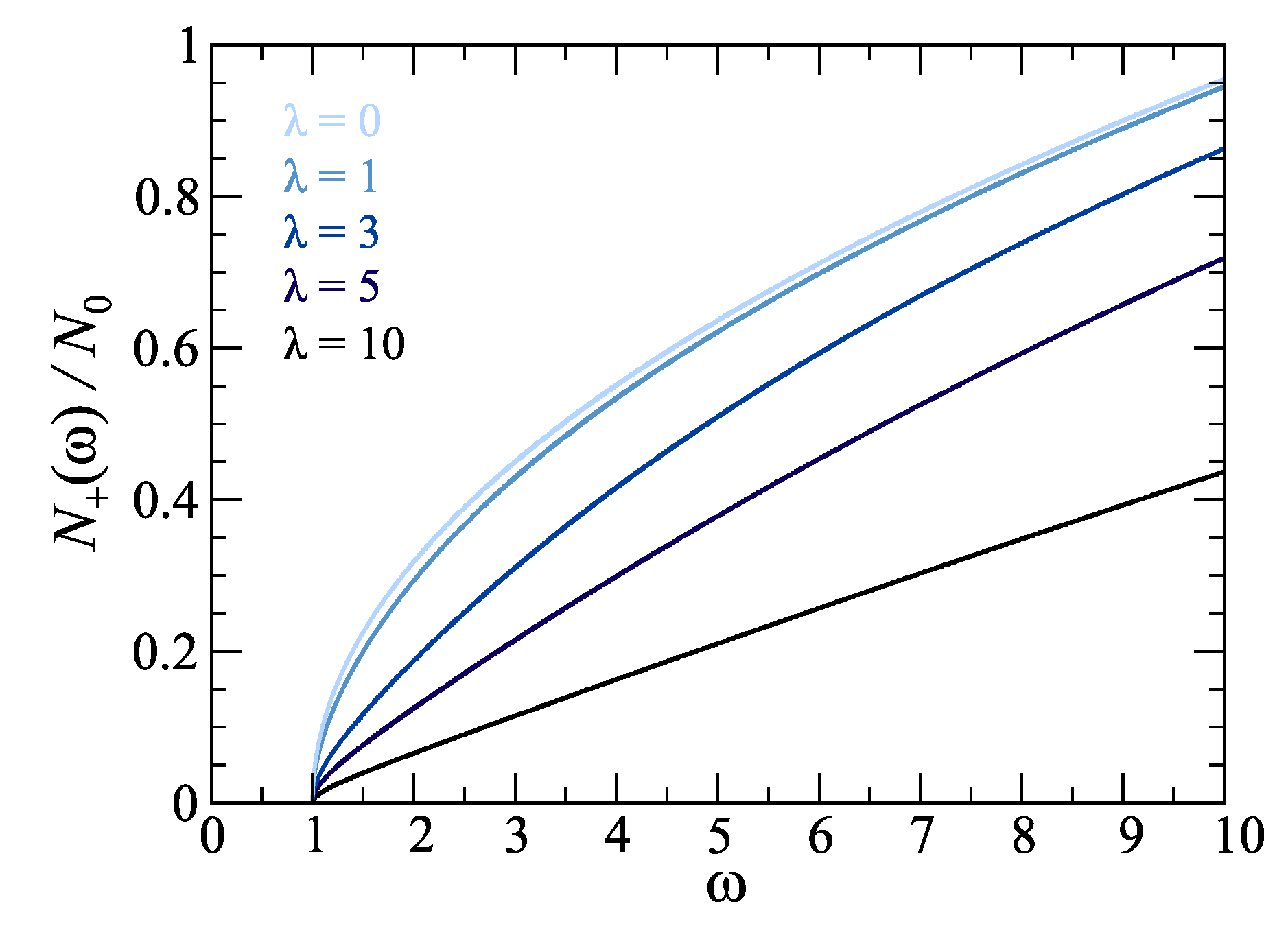
10), and using (13) and (14), we obtain DOS in the GP phase,
shown in Fig
Figure 7. As in the NLP case, we can determine the limiting values.
First, by expanding the expression (28) for energies just above the band gap, i.e.
, we obtain
Second, in the high energy limit,
, similarly to Equation (20), we obtain
The "square root behaviour" in both cases, resembling the 3D free electron gas, is not surprising since we work with the band with the elliptic point at its bottom.
Third, in the case of energies over which the parameter
is the dominant variable, i.e.
, by setting
we obtain
As expected, this is the same result as in Equation (23) (see
Figure 7, case
), which follows from the correct expansion of Equation (
3) with dominant
-term.
Finally, let us examine the
limit, in which the expression (29) reduces to
which is a DOS of the 3D parabolic insulator.
7. Conclusion
We present analytical results comprising electron bands and density of states (DOS) for the effective low-energy two-band electron Hamiltonian, which models the so-called nodal-loop phase (NLP) and the gapped phase (GP) depending on parameters. This way to model the real materials is quite common and useful for description of response to the low-energy excitations, the most common among them the different types of transport properties, such as optical conductivity for example, for systems with two bands close to the Fermi energy. Beside the common models, where the density of state naturally appears, such as the plasmon properties, Coulomb screening or superconductivity mechanisms, it has recently been shown that it plays a key role in description of the dynamical charge transport in the Holstein-like systems in which it turns out that electron relaxation can be described solely in terms of electron DOS [25]. In that sense, an analytical character of DOS, presented in this paper for the considered Hamiltonian, is of an utmost importance in order to understand the underlying mechanisms leading to properties of the above-mentioned quantities depending on it.
In this paper we present analysis of exactly those features. We observe a vanishing value of DOS at the Fermi energy (in the intrinsic case), followed by the linear increase with energy in the NLP case, typical for semimetalic systems, or square-root behaviour above the bottom of the band in the GP case, characteristic for 3D insulators with parabolic electron dispersion. Also, we provide a detailed description of DOS around the van Hove singularities appearing due to presence of the peculiar points in electron spectrum. In the NLP case the hyperbolic (saddle) point and the elliptic point are encountered, while the GP case features only the elliptical point at the bottom of the band. The good analysis of similar Hamiltonian with the NLP, from its topological properties to the real materials described by it, is given in Refs. [1,26]. On the other hand, an example of application of the NLP Hamiltonian to description of the optical conductivity is given in Refs. [23,27]. The band structure of the corresponding real systems can be quite complex, usually addressed by different ab initio methods [20,21]. This work is to complement those methods by the precise, analytical description of the bands and DOS properties in the most relevant region - the narrow interval around the Fermi energy located either in the vicinity of the nodal line or the band gap.
Author Contributions
Z.R., I.K. and D.R. contributed to this paper in terms of conceptualization, methodology, formal analysis and draft preparation. All authors have read and agreed to the published version of the manuscript.
Funding
This research was funded by the QuantiXLie Centre of Excellence, a project co-financed by the Croatian Government and European Union through the European Regional Development Fund — the Competitiveness and Cohesion Operational Programme (Grant KK.01.1.1.01.0004), and by the Scientific Exchange grant IZSEZ0_217543.
Conflicts of Interest
The authors declare no conflict of interest whatsoever.
References
- Yang, S. -Y., Yang, H., Derunova, E., Parkin, S. S. P., Yan, B. and Ali, M. N. Symmetry demanded topological nodal-line materials. Advances in Physics: X VOL. 3, NO.1, 1414631 (2018). [CrossRef]
- Bernevig, B. A., Hughes, T.L., Zhang, S.C. Quantum Spin Hall Effect and Topological Phase Transition in HgTe Quantum Wells. Science 314, 1757–1761 (2006). [CrossRef]
- Su, W.P., Schrieffer, J.R. and Heeger, A.J. Solitons in Polyacetylene. Phys. Rev. Lett. 42, 1698-1701 (1979). [CrossRef]
- Peierls, R.E. Quantum Theory of Solids, Clarendon Press, Oxford (1955), pp. 108.
- Jafari, S. A. Nonlinear optical response in gapped graphene. J. Phys.: Condens. Matter 24, 205802 (2012). [CrossRef]
- Wallace, P.R. The Band Theory of Graphite. Phys. Rev. 71, 622 (1947). [CrossRef]
- Kupčić, I. Damping effects in doped graphene: The relaxation-time approximation. Phys. Rev. B 90, 205426-1-15 (2014). [CrossRef]
- Carbote, J. P. Dirac cone tilt on interband optical background of type-I and type-II Weyl semimetals. Phys. Rev. B 94, 165111 (2016). [CrossRef]
- Montambaux, G., Piechon, F., Fuchs, J. N., Goerbig, M. O. Merging of Dirac points in a two-dimensional crystal. Phys. Rev. B 80, 153412 (2009). [CrossRef]
- Mukherjee, D. K., Carpentier, D., Goerbig, M. O. Dynamical conductivity of the Fermi arc and the Volkov-Pankratov states on the surface of Weyl semimetals. Phys. Rev. B 100, 195412 (2019). [CrossRef]
- Rukelj, Z., Homes, C.C., Orlita, M., Akrap, A. Distinguishing the gapped and Weyl semimetal scenario in ZrTe5: Insights from an effective two-band model. Phys. Rev. B 102, 125201 (2020). [CrossRef]
- Polatkan, S., Goerbig, M. O., Wyzula, J., Kemmler, R., Maulana, L.Z., Piot, B. A., Crassee, I., Akrap, A., Shekhar, C., Felser, C., Dressel, M., Pronin, A. V., Orlita, M. Magneto-Optics of a Weyl Semimetal beyond the Conical Band Approximation: Case Study of TaP. Phys. Rev. Lett. 124, 176402 (2020). [CrossRef]
- Ashby, P.E.C., Carbotte, J.P. Chiral anomaly and optical absorption in Weyl semimetals. Phys. Rev. B 89, 245121 (2014). [CrossRef]
- Peres, N.M., Santos, J.E. Strong light–matter interaction in systems described by a modified Dirac equation. J. Phys.: Condens. Matter 25, 305801 (2013). [CrossRef]
- Rukelj, Z., Akrap, A. Carrier concentrations and optical conductivity of a band-inverted semimetal in two and three dimensions. Phys. Rev. B 104, 075108-1-12 (2021). [CrossRef]
- Rukelj, Z., Radić, D. Topological Properties of the 2D 2-Band System with Generalized W-Shaped Band Inversion. Quantum Rep. 4, 476–485 (2022). [CrossRef]
- Barati, S., Abedinpour, S.H. Optical conductivity of three and two dimensional topological nodal-line semimetals. Phys. Rev. B 96, 155150 (2017). [CrossRef]
- Rukelj, Z., Radić, D. DC and optical signatures of the reconstructed Fermi surface for electrons with parabolic band. New J. Phys. 24, 053024-1-16 (2022). [CrossRef]
- Dressel, M., Grüner, G. Electrodynamics of Solids: Optical Properties of Electrons in Matter, Cambridge University Press, 2002.
- Bian, G., Chang, T. R., Zheng, H., Velury, S., Xu, S. Y., Neupert, T., Chiu, C. K., Huang, S. M., Sanchez, D. S., Belopolski, I., Alidoust, N., Chen, P. J., Chang, G., Bansil, A., Jeng, H. T., Lin, H. and Hasan M. Z. Drumhead surface states and topological nodal-line fermions in TlTaSe2. Phys. Rev. B 93, 121113(R) (2016). [CrossRef]
- Wang, X., Ding, G., Cheng, Z., Surucu, G., Wang, X. L., Yang, T. Novel topological nodal lines and exotic drum-head-like surface states in synthesized CsCl-type binary alloy TiOs. Journal of Advanced Research 22, 137-144 (2020). [CrossRef]
- Ashcroft, N. W. and Mermin, N. Solid State Physics, Saunders Collage, 1976.
- Yang, M. X., Luo, W. and Chen, W. Quantum transport in topological nodal-line semimetals. Advances in Physics: X VOL. 7, NO.1, 2065216 (2022). [CrossRef]
- Carbote, J. P., Nicol, E. J. Signatures of merging Dirac points in optics and transport. Phys. Rev. B 100, 035441 (2019). [CrossRef]
- Rukelj, Z. et al. to be published (accepted in the Phys. Rev. B).
- Fang, C., Weng, H., Dai, X. and Fang Z. Topological nodal line semimetals, Chinese Phys. B 25, 117106 (2016). [CrossRef]
- Kandel, S., Gumbs, G. and Berman, O.L. Optical Response of 3D Model Topological Nodal-line Semimetal. Advances in Nanosheets. IntechOpen, Jun. 28, 2023. [CrossRef]
|
Disclaimer/Publisher’s Note: The statements, opinions and data contained in all publications are solely those of the individual author(s) and contributor(s) and not of MDPI and/or the editor(s). MDPI and/or the editor(s) disclaim responsibility for any injury to people or property resulting from any ideas, methods, instructions or products referred to in the content. |
© 2023 by the authors. Licensee MDPI, Basel, Switzerland. This article is an open access article distributed under the terms and conditions of the Creative Commons Attribution (CC BY) license (http://creativecommons.org/licenses/by/4.0/).
