Submitted:
06 November 2023
Posted:
06 November 2023
You are already at the latest version
Abstract
This paper studies a multihop amplify-and-forward (AF) simultaneous wireless information and power transfer (SWIPT) relaying system. Each relaying node harvests energy using power splitting (PS) scheme from a part of its received signal to amplify and forward the rest the received signal to the next relay. Based on this system model and signal flow, we derived and solved the convex energy minimization problem with optimal PS ratio. The influence of processing cost was then investigated for the AF-SWIPT system with the decode-and-forward SWIPT as benchmark, where AF-SWIPT was found to be superior.
Keywords:
multihop amplify-and-forward (AF) relays
; power splitting (PS) ratio
; simultaneous wireless information and power transfer (SWIPT)
1. Introduction
The Internet-of-Things (IoT) connects network-enabled devices communicating with each other over the Internet. Hence, the objective of IoT is to integrate the physical world and the virtual world to attain a self-sustaining system [1]. Currently, research into the application of IoT for the creation of smart-cities, smart-homes, smart-energy, intelligent-transportation system, and many more is growing. An IoT network consists of the use of routing schemes, a gateway supporting communication between the different nodes and a central system [1]. These routing schemes facilitate either direct or relaying communication between a gateway and a particular node. The routing/relaying nodes can be opportunistically implemented by non-active user devices [1]. This results in the selected user nodes consuming their power in facilitating communication between the two user pairs [2,3]. This implies that, the selected users sacrifice their resources to facilitate relaying procedures [2,11]. The strain on the relay nodes can be mitigated by employing wireless power transfer (WPT) [1,2,3].
Recently, research into alternative wireless sources (e.g., radio frequency (RF) and light energy harvesting) of energy to power IoT devices is also increasing [1,2,3,4,5,6]. Such alternative wireless power sources are on the market, e.g., wi-charge technology (the wi-charger devices), Pi charger, energous RF chargers and Warp RF wireless charging systems. From literature, WPT using RF can be accomplished by using two different techniques, namely, simultaneous wireless information and power transfer (SWIPT), and wireless powered communication network (WPCN) [1,2,3,5]. SWIPT involves the transmission of wireless information signal and wireless power signal concurrently [1,2,3,5]. Time switching (TS) and power splitting (PS) are the two main techniques in order to implement SWIPT [1,2,3]. The successive transmission of wireless information signal and wireless power signal is used to accomplish WPCN [1,2,3].
Research on RF-based WPT has evolved from point-to-point systems, dual-hop cooperative systems to multi-hop cooperative systems. A few literature on both dual-hop and multi-hop cooperative systems can be found in [1,2,3,4,5,6,7,8,9]. In this paper, we extend the work in [1] which focused on a decode-and-forward (DF)-SWIPT multihop system model to an amplify-and forward (AF)-SWIPT multi-hop system model. Similar to the work in [1], we consider single-antenna nodes, SWIPT PS mode at each relay node, and the optimization problem on energy efficiency. Finally, the closed-form solution are obtained for our optimization problem. In the simulation results, we compare AF-SWIPT multi-hop systems to the DF-SWIPT in [1].
The rest of the paper is organized as follows, Section 2, Section 3, and Section 4 contains the the stepwise process in formulating the AF-SWIPT multi-hop optimization problem, the solutions for our optimization problem, and simulation results and discussion, respectively. Finally, concluding remarks are provided in Section 5.
2. System Model and Problem Formulation
The IoT network consists of the source node, K AF-SWIPT relays, and the destination node, are shown in Figure 1. Each node has a single antenna. The source is a base station (BS) which may consist of the data gateway and the external/central systems of the IoT network [11,12,13,15,16,17]. In order to increase the operation efficiency of the relay node, each relay node operates in SWIPT mode. A RF signal received at each relay is split using the PS ratio where a part of the signal is stored in battery in each relay via energy harvesting (EH). Then, the information processing (i.e., amplification and forwarding) is performed using the remaining RF signals, and then the transmission is performed to the next node with the harvested energy.
The structure of our AF-SWIPT relay is shown in Figure 2. Each relay has a battery, which can store energy and perform retransmission using it. Each AF-SWIPT relay performs EH using a power splitting (PS) scheme and operates in half-duplex mode.
We assume that the source node provides the channel state information (CSI) for all communication nodes. However, each relay and the destination node only knows the CSI for their communication channel. It is assumed that there is no direct link between the current node and the next second or more nodes. For example, there is no direct link between the first node and the third node.
The received RF signal at node from the previous node is given as
where is the channel coefficient between the current node and the previous node, and ∼(0,) represents the antenna noise at the current node. The channel is defined as , where is the large-scale fading coefficient, is the attenuation constant for a distance , is the pathloss exponent, is distance between the transmit and receive nodes and ∼(0,1) is the Rayleigh fading component. Next, the signal for EH and harvested energy at the kth relay node are written, respectively, as
where is the processing power for information decoding at destination node, is the transmit energy at source node, and signal for information transmission at the kth relay is represented by
where is the additional noise introduced by the information decoding (ID) circuitry. The signal-to-noise ratio (SNR) is expressed as
The signal to be transmitted to the kth relay is represented by
where is amplification factor, and is the information signal at source node.
We now consider the problem of optimizing the PS ratio at the relay nodes and energy at the source node . We aim to minimize the source transmit power, under the SNR of destination node constraint and PS ratio for each of the multihop links as
The solution to the above problem is provided in the following section, and the induction process will be attached to the Appendix A.
3. Problem Solution
In this section, we provide the solution of source transmit power minimization problem. The optimal transmit energy at the source node is expressed to
where is the SNR threshold constraint of the destination node. The optimal PS ratio at the kth node is written as
where , , and are defined as
4. Simulation Results
This section evaluates the performance of the AF-SWIPT system compared with the DF-SWIPT system as benchmark [1]. For the large-scale fading component, the attenuation constant dB, and the pathloss exponent are assumed. The distance between each node is m, the antenna noise variance dBm, and the energy conversion efficiency . We asuume that at destination node, because the destination node are received the enough power for decoding to the previous node. The PS ratio used for the suboptimal scheme is . The simulation results are obtained over random channel realizations.
Figure 3 shows the effect of each relay circuit power on . When is low, the effect on is insignificant, but as increases, also increases. Unlike AF-SWIPT, where signals are decoded only at destination nodes, DF-SWIPT has a larger of value because signals are decoded at all relay nodes before they are re-transmission.
A simulation result based on the influence of increasing number of relays, K, follows in Figure 4. Figure 4 shows that increases as the number of relays. The influence of affects all the relays. It is observed that, the AF-SWIPT system has a lower than the DF-SWIPT system. This is because there is no signal decoding (i.e., processing power) at the relays for AF-SWIPT, unlike in the DF-SWIPT. In the AF-SWIPT signal decoding occurs only at the destination. Therefore, processing power is used only at the destination for the AF-SWIPT, while processing power is used at all nodes in the DF-SWIPT.
Figure 5 shows a plot of the average versus the SNR threshold constrain (in dB). The optimal PS scheme shows a lower value than the suboptimal PS scheme. When is low, is very high, which seems to have a great influence on the with a low influence.
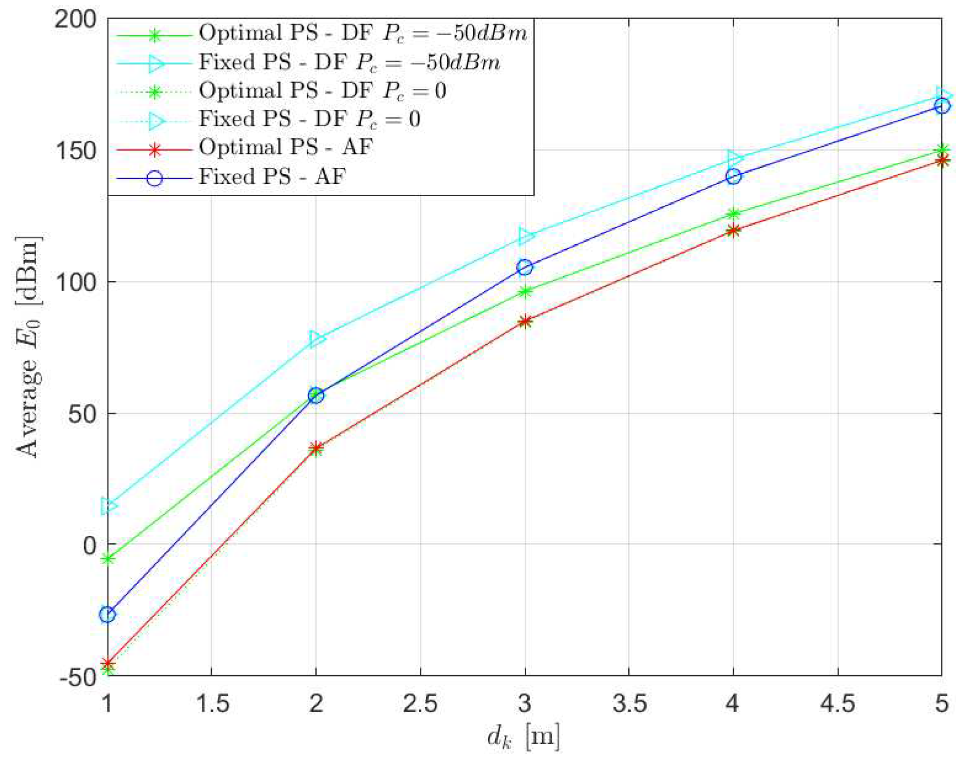
Figure 6 shows the against the internode distance, . As increases, more transmission power is required.
5. Conclusion
This paper investigated on the AF-SWIPT multi-hop cooperative relaying in IoT networks. Depending on the decoding cost, the AF-SWIPT system is more efficient compared to DF-SWIPT for data relaying. The AF-SWIPT source energy minimization optimization problem is presented in this paper. The idea is to promote energy efficiency through signal transmission energy cost. Simulation results showed the AF-SWIPT has better energy efficiency in terms of decoding cost compared to the DF-SWIPT. Possible extensions of this research are in the area of implementing the time-switching SWIPT protocol, MIMO multi-hop systems, WPCN multi-hop networks and development of routing algorithms for the multi-hop wireless powered networks.
Author Contributions
Conceptualization Asiedu, D.K.P.; Methodology, Original Draft Preparation and Writing Kim, K.J.; Review and editing Prince, A. and Kim, E; Supervision, Lee, K.-J..
Appendix A
The problem 8 is nonconvex with respect to and . By changing the problem, we rewrite problem 8 into and equivalent convex problem.
where . The Lagrangian of the problem A1 is defined with its KKT conditions given as
From A3, we can calculate as
and substituting A5 into A3,
Next, we change the problem A1 to find the optimal PS ratio as
and we formulate the Lagrangian of changed problem A7 to
The KKT conditions are represented as
where and are defined as bellows
References
- Asiedu, D. K. P.; Lee, H.; Lee, K.-J. Simultaneous wireless information and power transfer for decode-and-forward Multihop Relay systems in energy-constrained IoT networks. IEEE Internet Things J. 2019, 6, 9413–9426. [Google Scholar] [CrossRef]
- Mahama, S.; Asiedu, D. K. P.; Lee, K.-J. Simultaneous wireless information and power transfer for cooperative relay networks with battery. IEEE Access 2017, 5, 13171–13178. [Google Scholar] [CrossRef]
- Asiedu, D. K. P.; Mahama, S.; Jeon, S.-W.; Lee, K.-J. Optimal power splitting for simultaneous wireless information and power transfer in amplify-and-forward multiple-relay systems. IEEE Access 2018, 6, 3459–3468. [Google Scholar] [CrossRef]
- Lee, H.; Lee, K.-J.; Kim, H.; Lee, I. Joint transceiver optimization for MISO SWIPT systems with time switching. IEEE Trans. on Wireless Commun. 2018, 17, 3298–3312. [Google Scholar] [CrossRef]
- Lee, H.; Lee, K.-J.; Kim, H.; Lee, I. Wireless information and power exchange for energy-constrained device-to-device communications. IEEE Internet Things J. 2018, 5, 3175–3185. [Google Scholar] [CrossRef]
- Clerckx, B.; Zhang, R.; Schober, R.; Ng, D. W. K.; Kim, D. I.; Poor, H. V. Fundamentals of wireless information and power transfer: From RF energy harvester models to signal and system designs. IEEE Journal on Selected Areas in Communications 2018, 37, 4–33. [Google Scholar] [CrossRef]
- He, S.; Xie, K.; Chen, W.; Zhang, D.; Wen, J. Energy-aware routing for SWIPT in multi-hop energy-constrained wireless network. IEEE Access 2018, 6, 17996–18008. [Google Scholar] [CrossRef]
- Liu, X.; Wen, Z.; Liu, D.; Zou, J.; Li, S. Joint source and relay beamforming design in wireless multi-hop sensor networks with SWIPT. Sensors 2019, 19, 182. [Google Scholar] [CrossRef] [PubMed]
- Djiroun, F. Z.; Djenouri, D. Mac protocols with wake-up radio for wireless sensor networks: A review. IEEE Commun. Surveys & Tutorials 2017, 19, 587–618. [Google Scholar]
- Zhang, Z.; Pang, H.; Georgiadis, A.; Cecati, C. ; Wireless power transfer - an overview. IEEE Trans. Indust. Elect. 2018, 66, 1044–1058. [Google Scholar] [CrossRef]
- Ciuonzo, D.; Rossi, P. S.; Dey, S. Massive MIMO channelaware decision fusion. IEEE Trans. Signal Process. 2015, 63, 604–619. [Google Scholar] [CrossRef]
- Rossi, P. S.; Ciuonzo, D.; Kansanen, K.; Ekman, T. Performance analysis of energy detection for MIMO decision fusion in wireless sensor networks over arbitrary fading channels. IEEE Trans. Wireless Commun. 2016, 15, 7794–7806. [Google Scholar] [CrossRef]
- Raghavendra, C. S.; Sivalingam, K. M.; Znati, T. Wireless Sensor Networks.; Publisher: Springer USA, New York, 2006. [Google Scholar]
- Mao, M.; Cao, N.; Chen, Y.; Zhou, Y. Multi-hop relaying using energy harvasting. IEEE Wirless Commun. Letters 2015, 4. [Google Scholar]
- Sabor, N.; Sasaki, S.; Abo-Zahhad, M.; Ahmed, S. M. A comprehensive survey on hierarchical-based routing protocols for mobile wireless sensor networks: Review, taxonomy, and future directions. Wireless Commun. Mobile Comput. 2017, 2017, Art. no. 2818542. [Google Scholar] [CrossRef]
- Djiroun, F. Z.; Djenouri, D. MAC protocols with wake-up radio for wireless sensor networks: A review. IEEE Commun. Surveys Tuts. 2017, 19, 587–618. [Google Scholar] [CrossRef]
- Sandeep, D. N.; Kumar, V. Review on clustering, coverage and connectivity in underwater wireless sensor networks: A communication techniques perspective. IEEE Access 2017, 5, 11176–11199. [Google Scholar] [CrossRef]
Figure 1.
Multihop AF relay systems with SWIPT architecture.
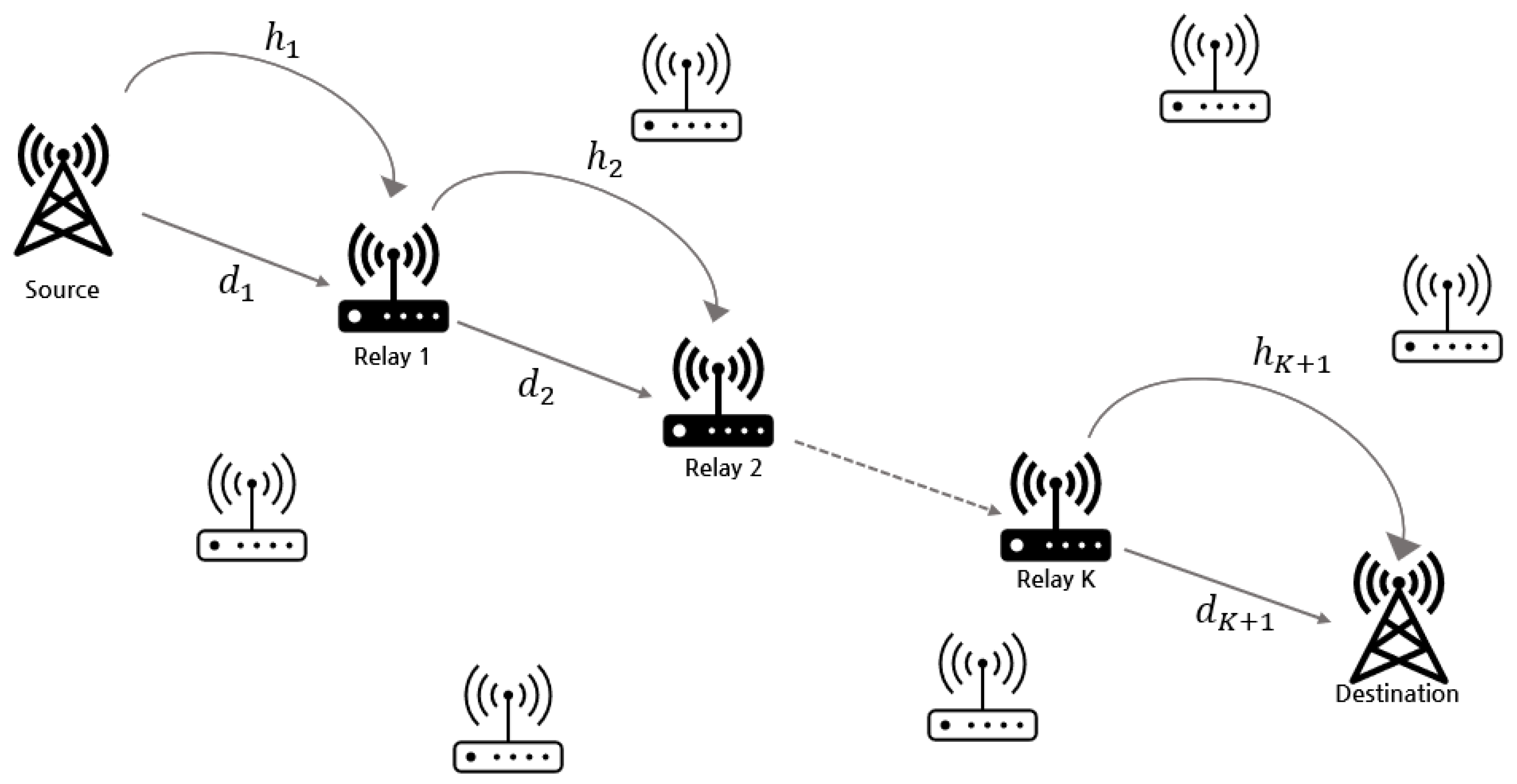
Figure 2.
Multihop AF relay node SWIPT architecture.
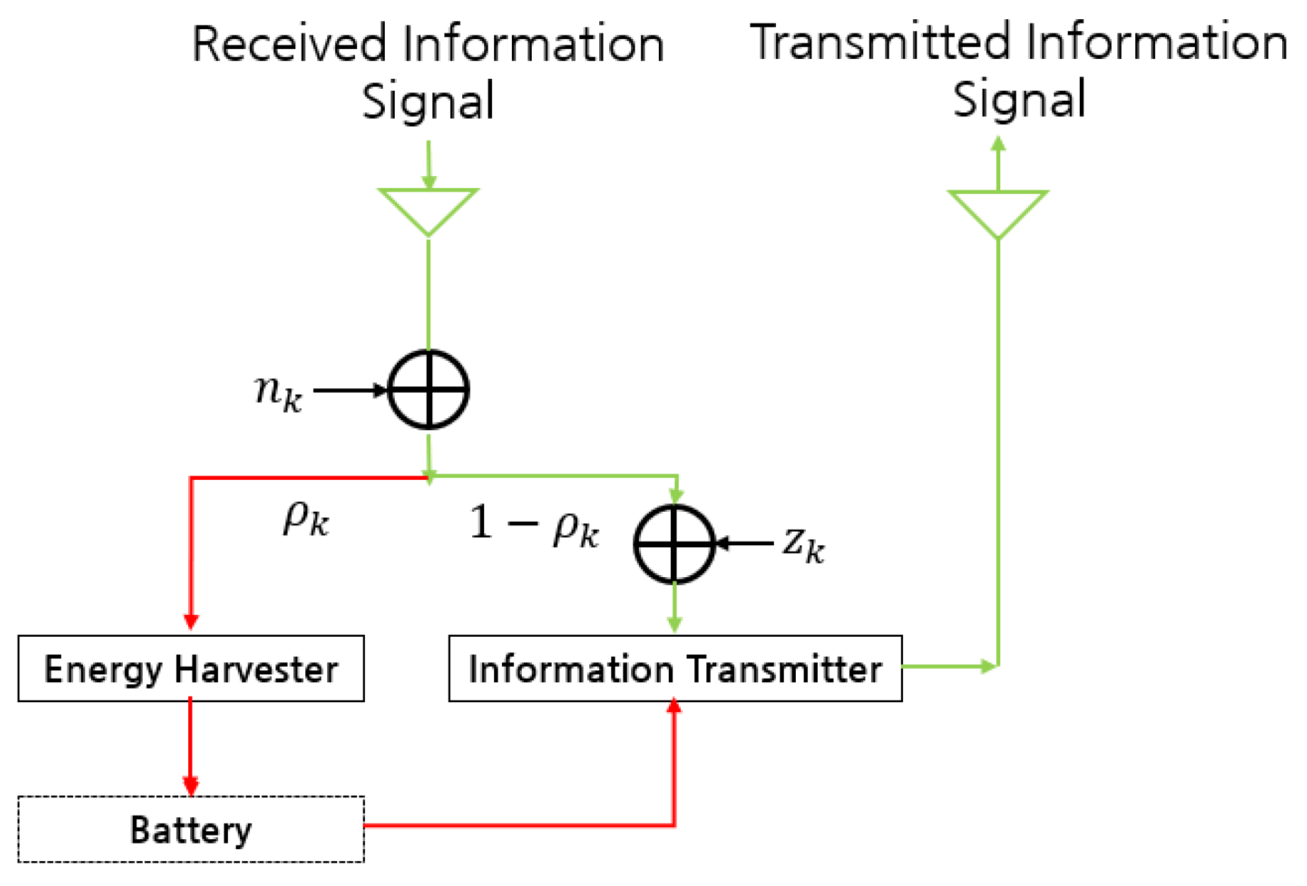
Figure 3.
The influence of increasing each relay ( dB).
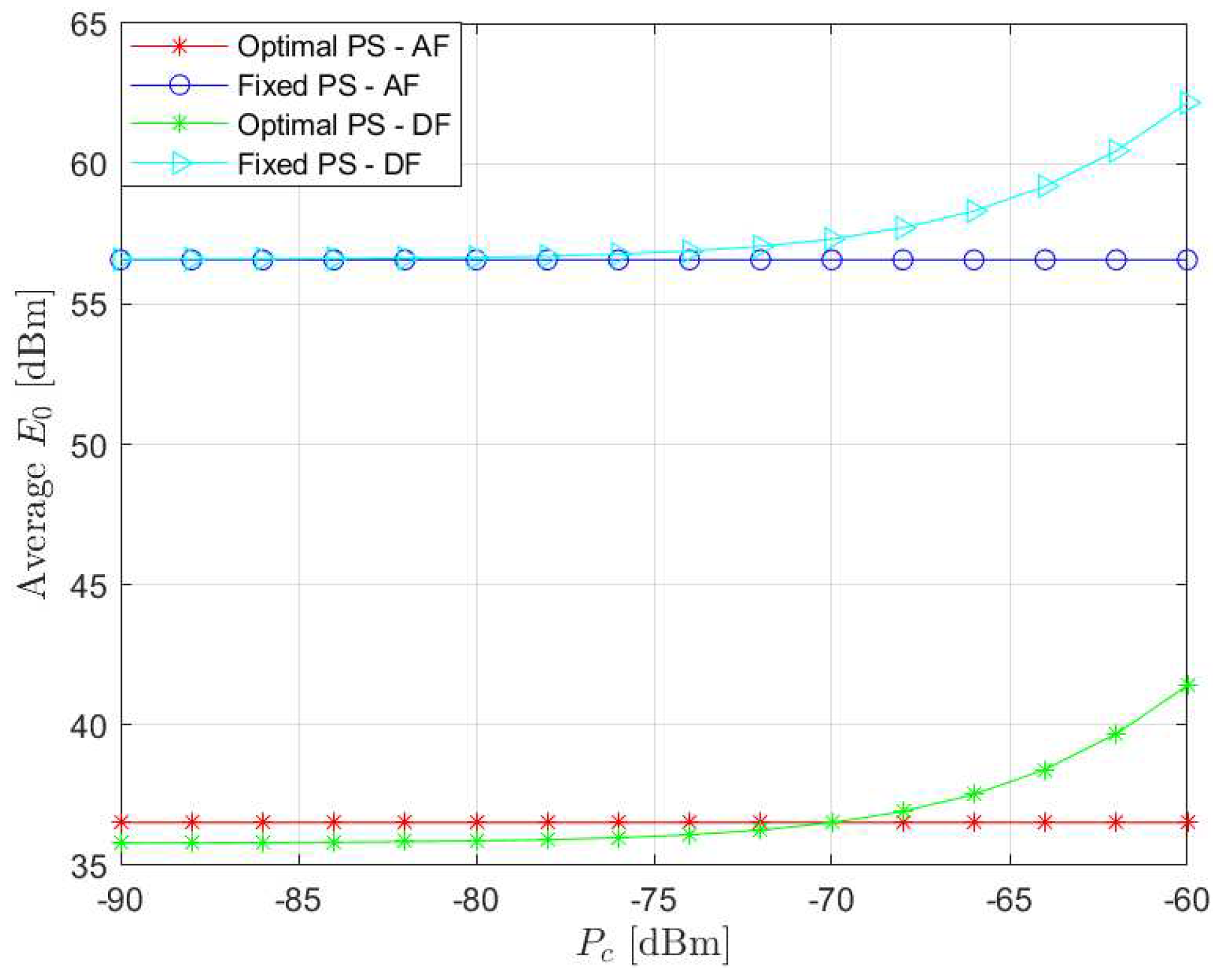
Figure 4.
Average against the number of relay nodes at dB, dBm.
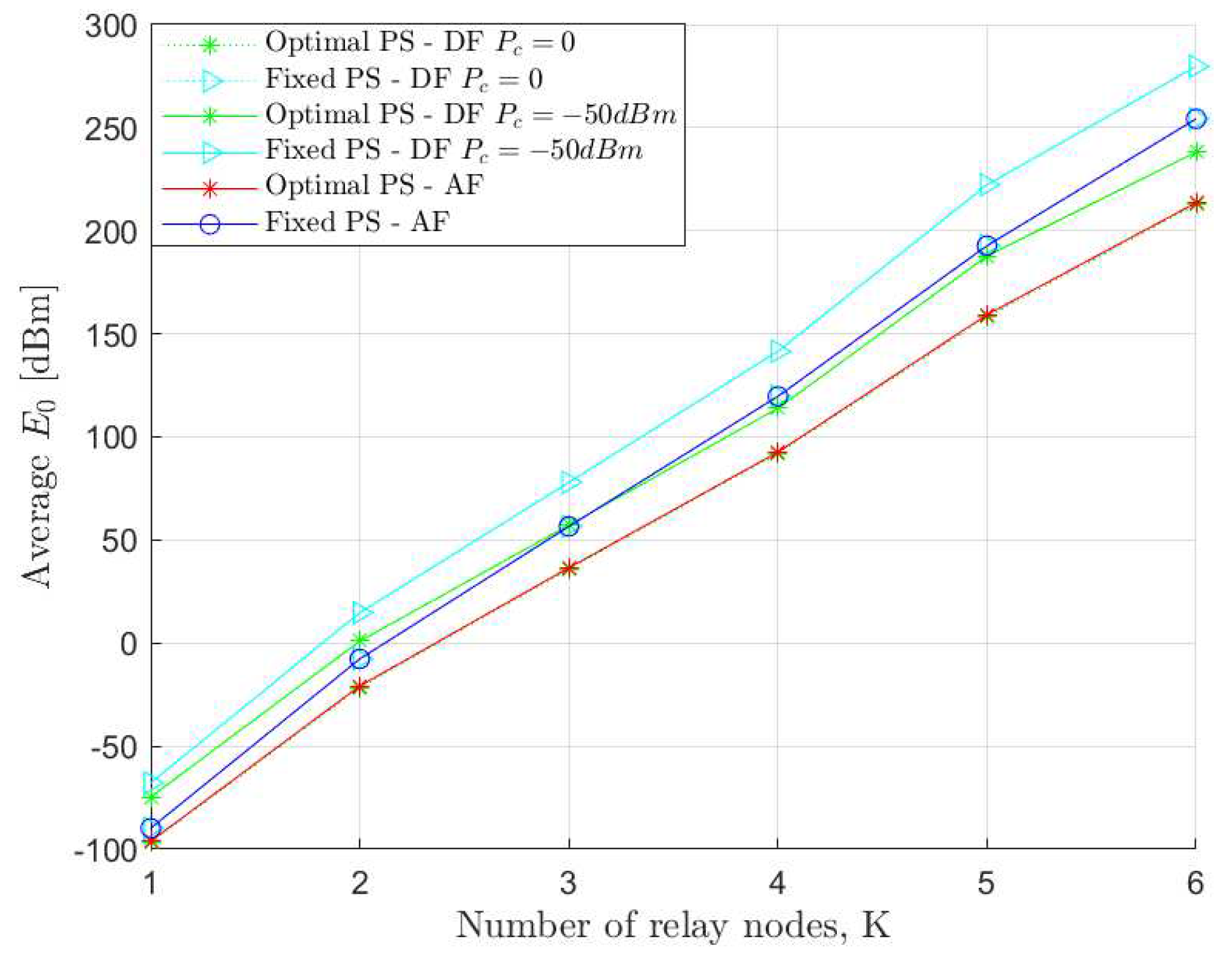
Figure 5.
Average relative to at , dBm.
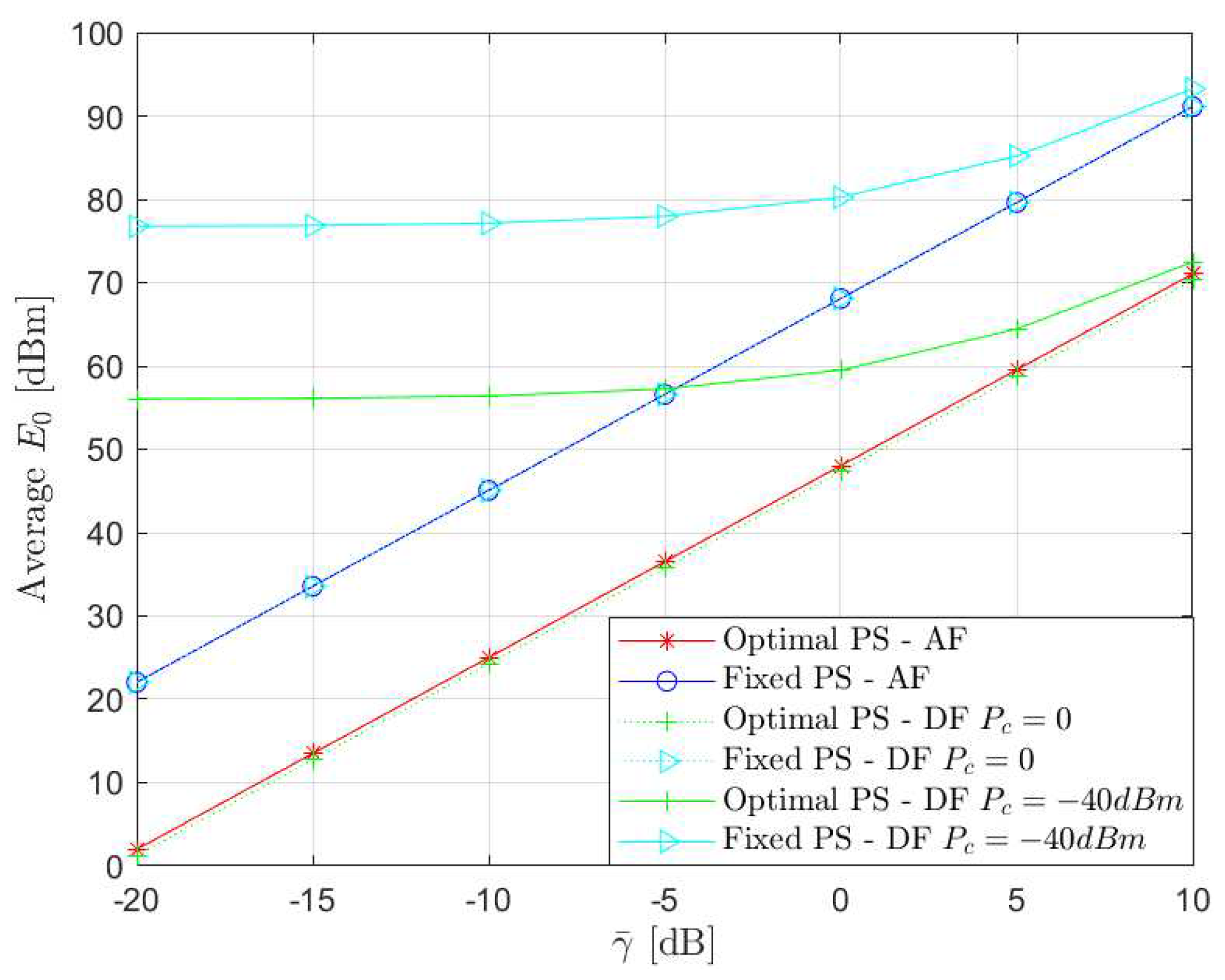
Figure 6.
Average relative to at , dBm.
Disclaimer/Publisher’s Note: The statements, opinions and data contained in all publications are solely those of the individual author(s) and contributor(s) and not of MDPI and/or the editor(s). MDPI and/or the editor(s) disclaim responsibility for any injury to people or property resulting from any ideas, methods, instructions or products referred to in the content. |
© 2023 by the authors. Licensee MDPI, Basel, Switzerland. This article is an open access article distributed under the terms and conditions of the Creative Commons Attribution (CC BY) license (http://creativecommons.org/licenses/by/4.0/).
Copyright: This open access article is published under a Creative Commons CC BY 4.0 license, which permit the free download, distribution, and reuse, provided that the author and preprint are cited in any reuse.


